MX960 AC Power Supply Description
Four types of AC power supplies can be used: normal-capacity, high-capacity, high-capacity second-generation, and high-voltage second-generation universal (HVAC/HVDC) power supplies (for more information on the HVAC/HVDC power supplies, see MX960 High-Voltage Second-Generation Universal (HVAC/HVDC) Power Supply Description. Each of the high-capacity power supplies has a corresponding AC receptacle located in the MX960 chassis directly above the power supply. High-capacity second-generation have two AC receptacles on the power supply itself. Each receptacle requires a dedicated AC power feed and a dedicated breaker. For all power supplies the circuit breaker protection should be designed according to National Electrical Code (NEC) or any similar local standard based on maximum drawn current of the power supply specified in this document. See AC Power Cord Specifications for the MX960 Router for more details.
Normal-capacity AC power supply configurations have one overall zone that provides power to all components in the MX960 chassis. The DC and high-capacity AC, and high-capacity second-generation AC power supply configurations have two zones each of which provide power to specific components in the MX960 chassis.
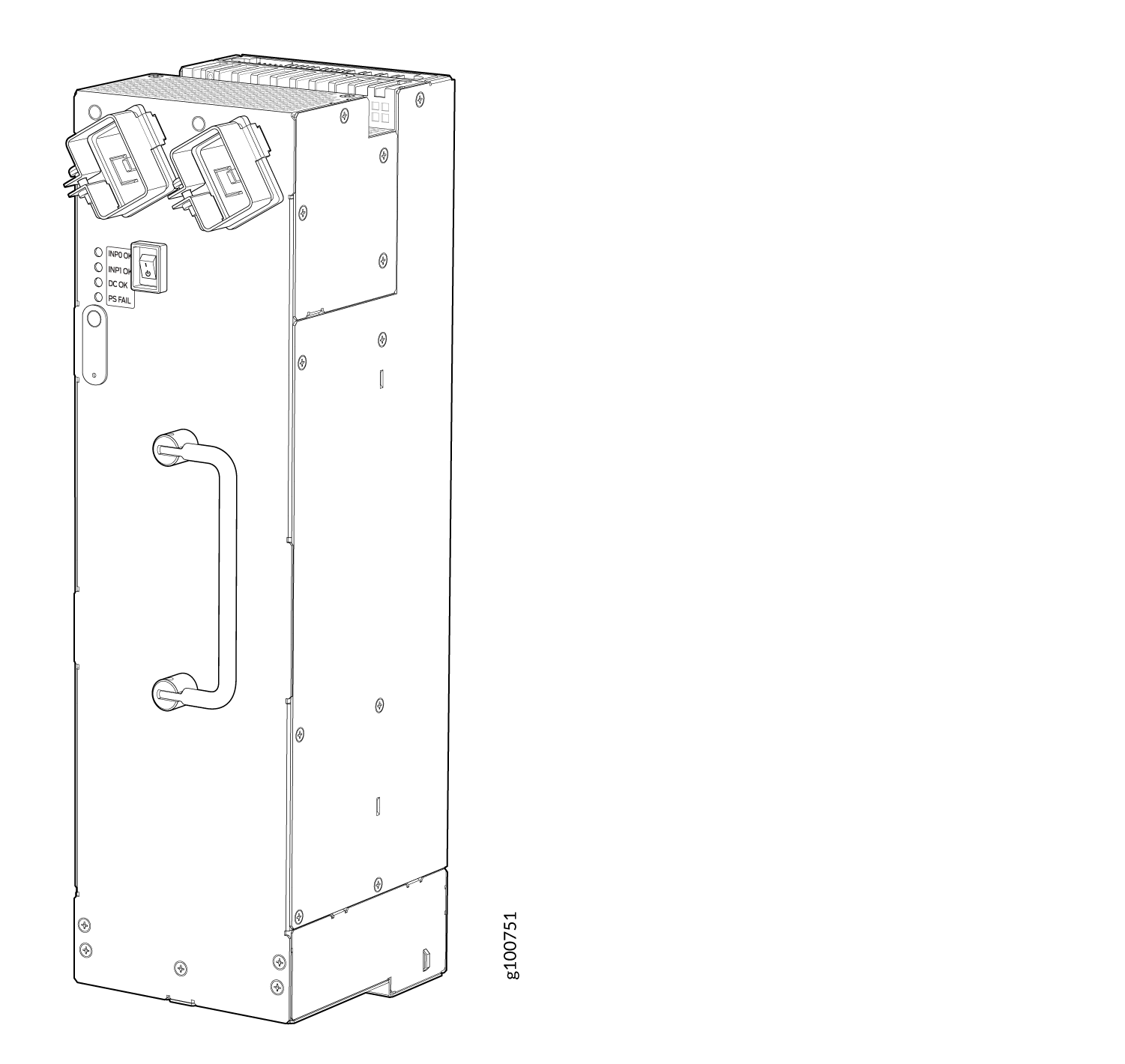
Figure 1 and Figure 2, Figure 3, and Figure 4 illustrate normal-capacity and high-capacity AC power supplies for the MX960.
The chassis is shown with the extended cable manager.
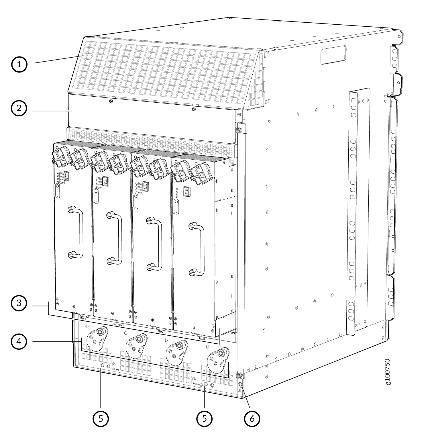
1 — Air exhaust | 4 — Power supply ejectors |
2 — Power distribution unit cover | 5 — Grounding points |
3 — Power supplies | 6 — ESD |
The chassis is shown without the extended cable manager.
The minimum number of power supplies must be present in the router at all times. Refer to Table 1.
| Router Model | Configuration | Minimum Required Number of Power Supplies | Model Number |
MX960 |
High-capacity AC |
One per zone x two zones = 2 power supplies |
PWR-MX960-4100-AC |
MX960 |
Normal-capacity AC |
Three power supplies |
PWR-MX960-AC |
MX960 |
High-capacity second-generation AC |
One per zone x two zones = 2 power supplies |
MX960-PSM-5K-AC |
Normal-Capacity AC Power Supplies
The MX960 can be powered by three normal-capacity AC power supplies (non-redundant configuration) or four normal-capacity AC power supplies (redundant configuration). In a non-redundant configuration, the three AC power supplies share power almost equally within a fully-populated MX960 system. In a redundant configuration there is full power redundancy meaning if one power supply fails or is removed, the remaining power supplies instantly assume the entire electrical load without interruption and provide full power for the maximum configuration for as long as the router is operational.
Each normal-capacity power supply must be connected to a dedicated AC power feed and a dedicated customer site circuit breaker. Juniper recommends that you use a 15 A (250 VAC) minimum, or as required by local code.
High-Capacity AC Power Supplies
The MX960 can also be powered by two high-capacity AC power supplies. The high-capacity power supplies must be installed in adjacent slots in the chassis. They can operate in one-feed mode or two-feed mode.
In one-feed mode, the power supplies output power at a reduced capacity (1700W). In two-feed mode, the power supplies provide power at full capacity (4100W). To operate the MX960 at full capacity, you must use two-feed mode. High-capacity power supplies require one power cord per feed. Therefore, to operate the MX960 at full capacity, you will need four power cords.
Each high-capacity AC power supply accepts two AC feeds in two unique AC receptacles, one receptacle located on the chassis and the other on the power supply.
When using the high-capacity AC power supplies in one-feed mode, plug one end of the power cord into the corresponding AC receptacle directly above the power supply in the chassis and the other end into an AC outlet. When using the high-capacity power supply in two-feed mode, you need two power cords. Plug one power cord into the AC receptacle on the chassis and then plug the other end into an AC outlet. Next, plug the second power cord into the AC receptacle on the AC power supply and plug the other end into an AC outlet.
In high-capacity AC power supply configurations, there are two zones that provide power to specific components in the MX system. No current sharing between power supplies is needed with the high-capacity system because the redundancy changes from 3+1 per system to 1+1 per zone.Table 2 lists the components that receive power for each zone in a high-capacity AC power supply configuration.
Chassis Power Configuration |
Zone |
Power Supply (PEM) |
Components Receiving Power |
|---|---|---|---|
MX960 AC high-capacity power supplies |
Zone 0 |
PEM 0 or 2 |
|
MX960 AC high-capacity power supplies |
Zone 1 |
PEM 1 or 3 |
|
High-Capacity Second-Generation AC Power Supplies
The MX960 can also be powered by four high-capacity second-generation AC power supplies. The high-capacity second-generation power supplies must be installed in adjacent slots in the chassis. They can operate in either one-feed mode or two-feed mode.
In the one-feed mode, the power supplies provide power at a reduced capacity (2000 W). In the two-feed mode, the power supplies provide power at full capacity (5100 W). To operate the MX960 at full capacity, you must use the two-feed mode. High-capacity second-generation AC power supplies require one power cord per feed. Therefore, to operate the MX960 at full capacity, you need eight power cords.
Each high-capacity second-generation AC power supply accepts two AC feeds in two C19/C20 AC receptacles, both receptacles are located on the power supply. Do not use the receptacle located on the chassis. For supported power cables, see AC Power Cord Specifications for the MX960 Router.
When using the high-capacity second-generation AC power supplies in one-feed mode, plug one end of the power cord into the corresponding AC receptacle directly on the power supply and the other end into an AC outlet. When using the high-capacity second-generation AC power supply in two-feed mode, you need two power cords. Plug both power cords into the AC receptacles on the power supply the other ends of the cable into AC outlets.
In high-capacity second-generation AC power supply configurations, there are two zones that provide power to specific components in the MX system. Redundancy is 1+1 per zone. Table 2 lists the components that receive power for each zone in a high-capacity AC power supply configuration.
Chassis Power Configuration |
Zone |
Power Supply (PEM) |
Components Receiving Power |
|---|---|---|---|
High-capacity second-generation AC power supplies |
Zone 0 |
PEM 0 or 2 |
|
High-capacity second-generation AC power supplies |
Zone 1 |
PEM 1 or 3 |
|
Understanding Input Mode Switch (DIP Switch) Settings
Each PSM has two input mode switches (DIP switches) on the faceplate. The DIP switches provide critical information to the power management subsystem to help generate alarms in case of a feed failure or a wrong connection. Each PSM has an LED per feed indicating whether the feed is active and whether the feed is properly connected. You must set the DIP switch on each high-capacity AC or high-capacity second-generation AC power supply according to how many feeds are connected. When one feed is connected, the system is running in reduced capacity mode. When two feeds are connected the system is running in full-capacity mode. Use these DIP switch settings:
Position-0 indicates one AC feed is present
Position-1 indicates two AC feeds are present
Refer to Figure 5.
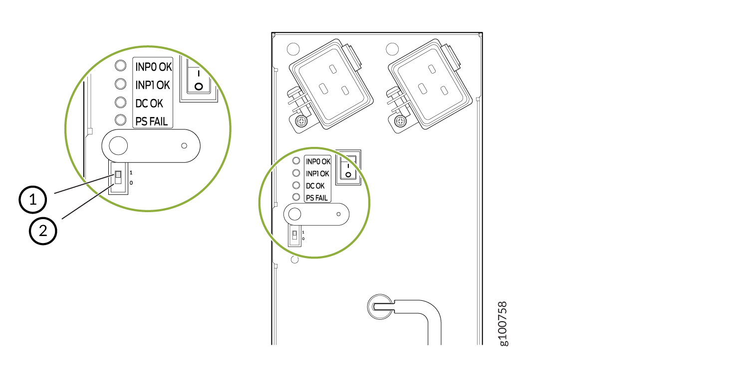
1 — Position 1 indicates two AC feeds are present | 2 — Position 0 indicates one AC feeds is present |
Use the show chassis power command to verify that
the DIP switch settings on the high-capacity AC power supplies are
set to the correct position. Here are examples of the command output:
Example 1: Proper setting of the DIP switch
user@host>show chassis power
PEM 0:
  State:     Online
  AC input:  OK (2 feed expected, 2 feed connected)
  Capacity:  4100 W (maximum 4100 W)
  DC output: 855 W (zone 0, 15 A at 57 V, 20% of capacity)

PEM 1:
  State:     Online
  AC input:  OK (1 feed expected, 1 feed connected)
  Capacity:  1700 W (maximum 4100 W)
  DC output: 969 W (zone 1, 17 A at 57 V, 57% of capacity)
In Example 1, PEM 0 is running at full capacity (4100 W) with two AC feeds expected and two AC feeds connected. This indicates that the DIP switch is properly set to Position 1 since two AC feeds are connected. The example also shows that PEM 1 is running at reduced capacity (1700W) with one AC feed expected and one AC feed connected. This indicates that the DIP switch is correctly set to Position 0 since one feed is present.
Example 2 shows the show chassis power command output when the DIP switch is set improperly:
Example 2: Improper Setting of the DIP Switch
user@host>show chassis power
PEM 0:
  State:     Online
  AC input:  OK (2 feed expected, 2 feed connected)
  Capacity:  4100 W (maximum 4100 W)
  DC output: 0 W (zone 0, 0 A at 56 V, 0% of capacity)

PEM 1:
  State:     Present
  AC input:  Check (2 feed expected, 1 feed connected)
  Capacity:  1700 W (maximum 4100 W)
The PEM 0 status indicates the system
is Online, the AC Input is OK, is running at full capacity (4100
W) with two AC feeds expected and two AC feeds connected. But notice
the status for PEM 1. The State is Present and the AC input is Check (2 feed expected, 1
feed connected). This indicates there is a mismatch
between the DIP switch setting and the number of feeds connected.
Therefore, the power supply is running at reduced capacity (1700 W).
If PEM 1 should be running at full-capacity, verify that there are
two feeds connected to the power supplies and the DIP switch is set
to position 1.