MX960 Dense Port Concentrator Description
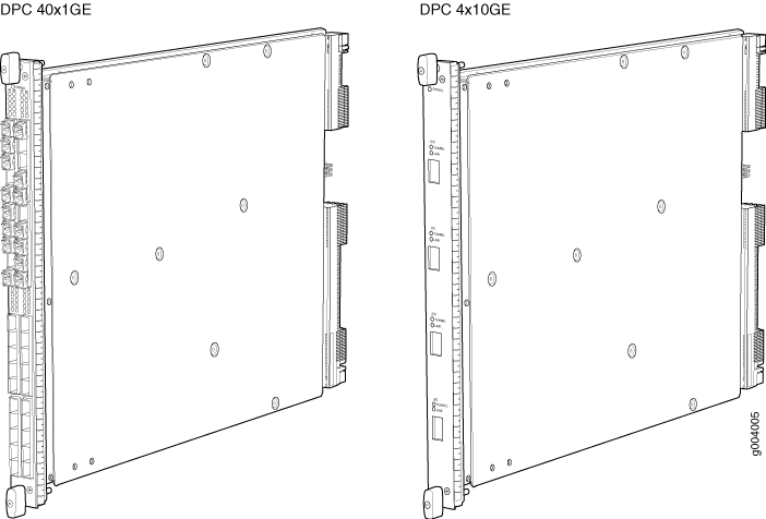
A Dense Port Concentrator (DPC) is optimized for Ethernet density. Figure 1 shows two examples of DPCs. For a list of the DPCs supported, see the MX Series Interface Module Reference.

The DPC assembly combines packet forwarding and Ethernet interfaces on a single board, with either two or four 10-Gbps Packet Forwarding Engines. Each Packet Forwarding Engine consists of one I-chip for Layer 3 processing and one Layer 2 network processor. The DPCs interface with the power supplies and Switch Control Boards (CBs).
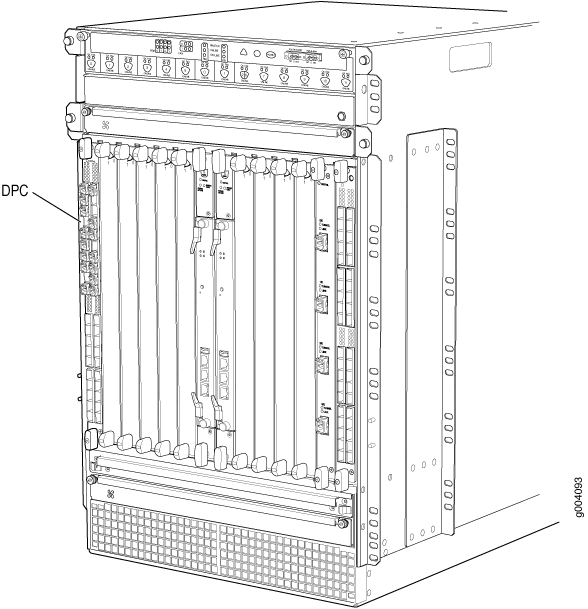
The router has 11 dedicated DPC slots. DPCs install vertically in the front of the router (see Figure 2). The dedicated DPC slots are numbered 0 though 5, and 7 though 11, left to right. An additional multifunction slot labeled 2/6 supports either an SCB or a DPC. A DPC can be installed in any slot that supports DPCs. You can install any combination of DPC types in the router.
If a slot is not occupied by a DPC, a DPC blank panel must be installed to shield the empty slot and to allow cooling air to circulate properly through the router.
DPCs are hot-removable and hot-insertable. When you install a DPC in an operating router, the Routing Engine downloads the DPC software, the DPC runs its diagnostics, and the Packet Forwarding Engines housed on the DPC are enabled. Forwarding on other DPCs continues uninterrupted during this process.

DPC Components
Each DPC consists of the following components:
DPC cover, which functions as a ground plane and a stiffener.
Fabric interfaces.
Two Gigabit Ethernet interfaces that allow control information, route information, and statistics to be sent between the Routing Engine and the CPU on the DPCs.
Two interfaces from the SCBs that enable the DPCs to be powered on and controlled.
Physical DPC connectors.
Two or four Packet Forwarding Engines.
Midplane connectors and power circuitry.
Processor subsystem, which includes a 1.2-GHz CPU, system controller, and 1 GB of SDRAM.
Online button—Takes the DPC online or offline when pressed.
LEDs on the DPC faceplate. For more information about LEDs on the DPC faceplate, see the MX Series Interface Module Reference.
Two LEDs, located on the craft interface above the DPC, display the status of the DPC and are labeled OK and FAIL.
