Determining DC Power Requirements for Your MX2020 Router
This topic describes the MX2020 DC power subsystem, power zones, and DC power usage to help you determine which Power Supply Modules (PSMs) are suitable for your router configuration.
We recommend that you provision power according to the maximum input current listed in the power subsystem electrical specifications (see MX2000 Router DC (-48 V) Power Subsystem Electrical Specifications).
MX 2020 DC Power Subsystem Components
The MX2020 DC power system is comprised of two subsystems. Each subsystem provides power to:
10 line-card slots
Nine DC Power Supply Modules (PSMs)
Two DC Power Distribution Modules (PDMs)
20 Modular Port Concentrators (MPCs) (10 MPCs per zone)
Two fan trays
Eight Switch Fabric Boards (SFBs)
Two Control Board and Routing Engines (CB-REs)
Understanding Power Zones in the MX2020 DC Power Subsystem
The MX2020 DC power subsystem has two power zones: zone 0 and zone 1. Some FRUs draw power only from zone 0, some FRUs draw power only from zone 1, and some FRUs draw power from both zone 0 and zone 1. When calculating power requirements, ensure there is adequate power for each zone. Each zone needs to provide 70% of the total power required by shared FRUs. This means 140% of the power required by the FRUs is available in the two power zones combined.
There are two types of DC power subsystems available for the MX2020: a “base” DC power subsystem (MX2020-BASE-DC) and an “optimized” or premium DC power subsystem (MX2020-PREMIUM2-DC). The fan trays in an optimized DC power subsystem draw power from the power zones differently than the fan trays in a base DC power subsystem. In a base DC power subsystem, two of the four fan trays draw power from both zones. In the optimized DC power subsystem, two of the fan trays draw power from only one zone. Because of this, the optimized power subsystem requires less power. Since the two fantrays share power in a zone, they only require 100% of the power they are rated at (not 140%). This is a net savings of 40% * 1700W/fantray * 2 for the system and half that amount per power zone.
70% of the total power from zone 0 + zone 1 must be provided by each zone in the calculation.
Four DC Power Supply Modules (PSMs) per zone are mandatory for the MX2020 router with DC Power Distribution Modules (PDMs).
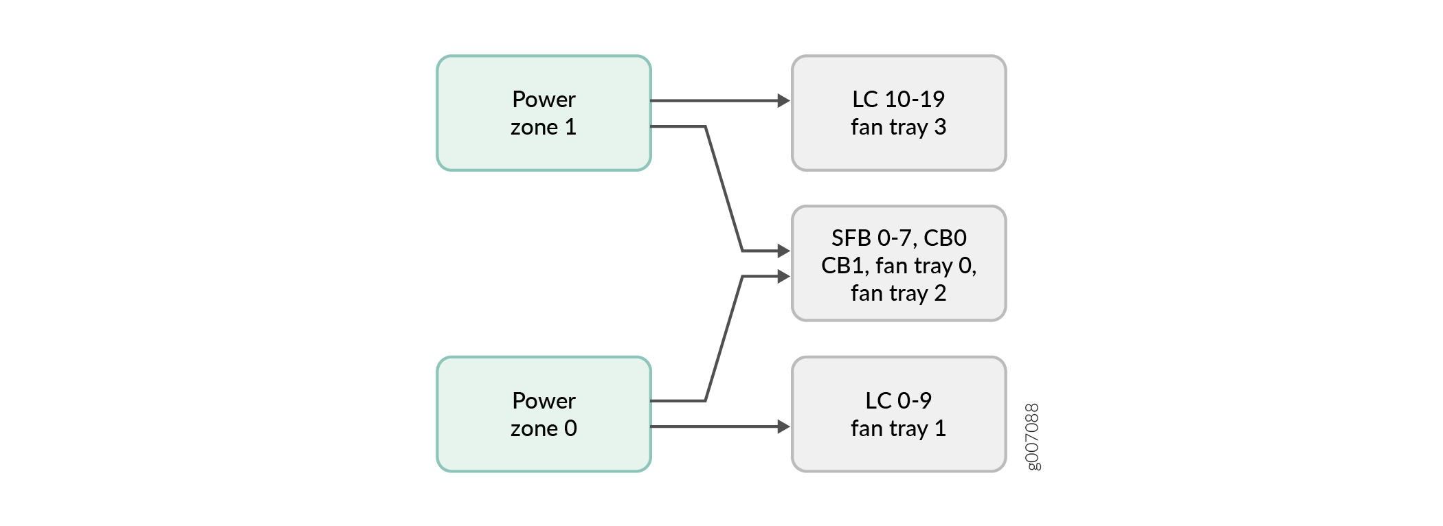
As illustrated in Figure 1 and described in Table 1, the power zones in the MX2020 DC base power subsystem distribute power to FRUs as follows:
Zone 0 powers only line card slots 0-9, and fan tray 1
Zone 1 powers only line card slots 10-19, and fan tray 3
-
Zone 0 + Zone 1 (both zones provide power) to CB-RE slot 0 and CB-RE slot 1, fabric card slots 0-7, and fan tray 0 and 2
Note:MX2020 routers do not support power redundancy mode for the MX2000-SFB3 fabric card in both the power zones.
Chassis Power Configuration |
Power Zone |
Power Distribution Module (PDM) |
Power Supply Module (PSM) |
Components Receiving Power |
|---|---|---|---|---|
DC power to lower half of MX2020 components |
Lower (zone 0) |
PDM 0 and 1 |
PSM slots 0 through 8 |
|
DC power to upper half of MX2020 components |
Upper (zone 1) |
PDM 2 and 3 |
PSM slots 9 through 17 |
|
Zone 0 + Zone 1 |
|
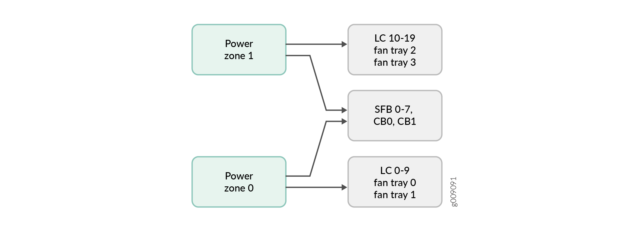
As illustrated in Figure 2 and described in Table 2, the power zones in MX2020 DC optimized power subsystems distribute power to FRUs as follows:
Zone 0 powers only line card slots 0-9, and fan trays 0 and 1
Zone 1 powers only line card slots 10-19, and fan trays 2 and 3
Zone 0 and Zone 1 (both zones provide power) to CB-RE slot 0 and CB-RE slot 1, and fabric card slots 0-7
Chassis Power Configuration |
Power Zone |
Power Distribution Module (PDM) |
Power Supply Module (PSM) |
Components Receiving Power |
|---|---|---|---|---|
DC power to lower half of MX2020 components |
Lower (zone 0) |
PDM 0 and 1 |
PSM slots 0 through 8 |
|
DC power to upper half of MX2020 components |
Upper (zone 1) |
PDM 2 and 3 |
PSM slots 9 through 17 |
|
|
Zone 0 + Zone 1 |
|
Calculating the DC Power Requirements for Your MX2020 Router
Follow these steps to calculate the DC power requirements for your MX2020 Router configuration.
Calculate the total output power required for your MX2020 FRUs.Table 3 shows the typical power usage for the MX2020 DC power subsystem FRUs.
Table 3: Typical DC Power Usage for MX2020 Router Component
Model Number
Power Requirement (Watts) with 91% Efficiency
Base chassis
CHAS-BP-MX2020
Fan trays (upper and lower)
MX2000-FANTRAY
1700 W * 4 = 6800 W
MPC
MPC-3D-16XGE-SFPP
440 W * 20 = 8800 W
ADC
ADC
150 W * 20 = 3000 W
CB-RE
RE-MX2000-1800X4
250 W * 2 = 500 W
SFB—slots 0 through 7
MX2000-SFB
220 W * 8 = 1760 W
MX2020 DC power subsystem (upper and lower half of chassis, 60 A feeds to each PDM input)
MX2020 DC power subsystem (upper and lower half of chassis, 80 A feeds to each PDM input)
2100 W * 8 PSMs=16,800 W (+ 1 PSM@2100 W redundant capacity)
2500 W * 8 PSMs=20,000 W (+ 1 PSM@2500 W redundant capacity)
MX2020 DC power subsystem (upper and lower half of chassis, 240-V feeds to each PDM input)
2500 W * 8 PSMs=20,000 W (+ 1 PSM@2500 W redundant capacity)
A portion of power from each zone is reserved to power critical FRUs. These FRUs allow the system to operate even if power to a complete zone fails.
Table 4: Power Reservation for MX2020 Router Configuration to Power Critical FRUs Switch Fabric Board (SFB)
Power Reserved for the Critical FRUs
Power Reserved for the Critical FRUs with Droop sharing between the Two Zones
Maximum Power Allocated for the SFB
MX2000-SFB-S
7360 W
5662 W
This number assumes a 70/30% load on the power zones when droop sharing is enabled.
220 W
MX2000-SFB2-S
7840 W
5998 W
This number assumes a 70/30% load on the power zones when droop sharing is enabled.
280 W
MX2000-SFB3
7760 W
6590 W
Note:MX2020 routers do not support power redundancy mode for the MX2000-SFB3 fabric card in both the power zones.
540 W
Evaluate the power budget, including the budget for each configuration if applicable, and check the required power against the maximum output power of available PSM options. Table 5 lists the MX2020 PSMs, their maximum output power, and unused power (or power deficit).
Table 5: MX2020 PSM DC Output Power Budget Power Supply Module
Maximum Output Power of Power Supply Module (Watt)
Maximum Output Power for System (Watt)—including redundant capacity
MX2020 DC PSM 60 A (feed to each input)
2100
37,800
MX2020 DC PSM 80 A or DC PSM (240 V China) (feed to each input)
2500
45,000
Calculate input power. Divide the total output requirement by the efficiency of the PSM. Refer to Table 6.
Table 6: Calculating DC Input Power Power Supply Module
Power Supply Module Efficiency
Output Power Requirement (Watt)—per PSM
Input Power Requirement (Watt)—per PSM
MX2020 DC PSM 60 A
91%
2100
2307
MX2020 DC PSM 80 A or DC PSM (240 V China)
91%
2500
2747
Calculate thermal output (BTUs) for cooling requirements. Multiply the input power requirement (in watts) by 3.41. Refer to Table 7.
Table 7: Calculating DC Thermal Output (BTUs) Loaded Chassis Heat Load
Thermal Output (BTUs per hour)
Loaded chassis configuration
34.5 KW divided by 0.91 * 3.41 = 129,280 BTU/hr (Zone 0 output. The calculation method for Zone 1 is the same as for Zone 0).
34.5 KW of output power consumed by the chassis. This is the maximum output the chassis can consume in a redundant configuration. The input power is 34.5 divided by 0.91 = 37.9 KW.