EX3400 Chassis
Front Panel of an EX3400 Switch
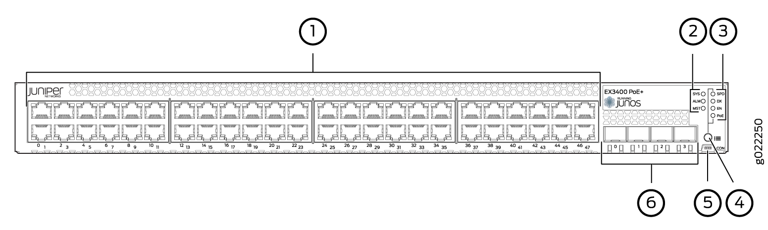
The front panel of an EX3400 switch consists of the following components:
-
RJ-45 ports:
-
Depending on the switch model, 24 or 48 RJ-45 ports (labeled 0 through 23 or 0 through 47) that support 10/100/1000BASE-T Gigabit Ethernet connectors
-
PoE available in all RJ-45 ports in EX3400-24P and EX3400-48P models
-
PoE not available in any network port in EX3400-24T, EX3400-24T-DC, EX3400-48T, EX3400-48T-AFI, and EX3400-48T-DC models
-
-
Three chassis status LEDs
-
Four port status mode LEDs in models with PoE capability and three port status mode LEDs in models without PoE capability
-
One Factory Reset/Mode button
-
One Mini-USB console port (the Mini-USB Type-B console port accepts a Mini-B plug (5-pin) connector to connect to the console management device)
-
Four uplink ports that support SFP+ transceivers, SFP transceivers, or a combination of these transceivers. These uplink ports are configured as network ports by default. To use the uplink ports to interconnect Virtual Chassis members, you must configure them as VCPs. See Setting an Uplink Port on an EX Series or QFX Series Switch as a Virtual Chassis Port.
Figure 1 shows the front panel of an EX3400 switch with 24 Gigabit Ethernet ports. Figure 2 shows the front panel of an EX3400 switch with 48 Gigabit Ethernet ports.

1 — RJ-45 ports | 4 — Factory Reset/Mode button |
2 — Chassis status LEDs | 5 — Mini-USB console port |
3 — Port status mode LEDs. The LED labeled PoE is present only on models with PoE capability. | 6 — Uplink ports |
1 — RJ-45 ports | 4 — Factory Reset/Mode button |
2 — Chassis status LEDs | 5 — Mini-USB console port |
3 — Port status mode LEDs. The LED labeled PoE is present only on models with PoE capability. | 6 — Uplink ports |
Rear Panel of an EX3400 Switch
The rear panel of the EX3400 switch consists of the following components:
-
1 USB port
-
1 management Ethernet port that supports an RJ-45 connector
-
1 RJ-45 console port (the RJ-45 console port accepts a cable with an RJ-45 connector to connect to the console management device)
-
1 protective earthing terminal
-
2 QSFP+ uplink ports. These uplink ports are configured as Virtual Chassis ports (VCPs) by default. You can use these uplink ports to interconnect Virtual Chassis members. To use the QSFP+ uplink ports as network ports, you must configure them as network ports.
-
1 ESD point
-
2 fan modules
-
CLEI code label
-
Serial Number ID Label
-
1 AC power supply or DC power supply
-
Empty slot for power supply covered by a blank panel or DC power supply
Figure 3 shows the rear panel of an EX3400 switch with AC power supply.
The power cord retainer extends out of the chassis by 3 in. (7.62 cm). The fan module handle extends out of the chassis by 1.2 in. (3 cm).
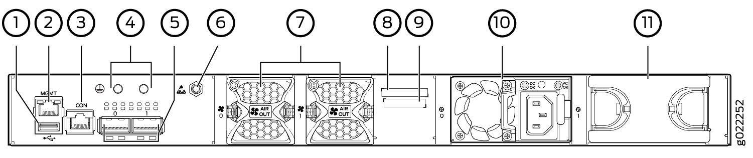
1 — USB port | 7 — Fan modules |
2 — Management Ethernet port | 8 — CLEI code label |
3 — RJ-45 console port | 9 — Serial Number ID Label |
4 — Protective earthing terminal | 10 — AC power supply |
5 — QSFP+ uplink ports | 11 — Empty slot for power supply covered by a blank panel |
6 — ESD point |
Figure 4 shows the rear panel of an EX3400 switch with DC power supply.
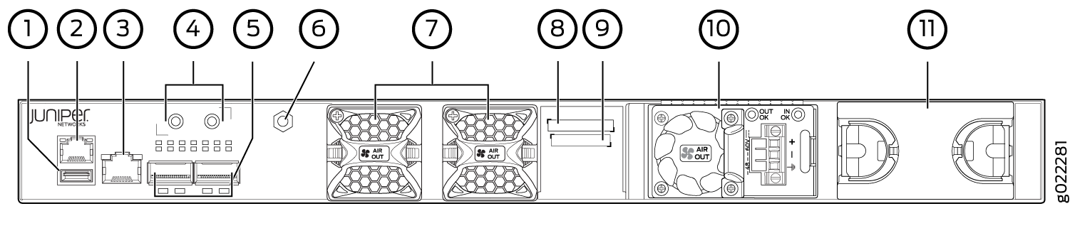
1 — USB port | 7 — Fan modules |
2 — Management Ethernet port | 8 — CLEI code label |
3 — RJ-45 console port | 9 — Serial Number ID Label |
4 — Protective earthing terminal | 10 — DC power supply |
5 — QSFP+ uplink ports | 11 — Empty slot for power supply covered by a blank panel |
6 — ESD point |
EX3400 switches shipped after 2 February, 2017 have serial number ID label on the side panel of the chassis and on the rear panel of the chassis. EX3400 switches shipped before 2 February, 2017 have the serial number ID label only on the side panel of the chassis.
Chassis Status LEDs in EX3400 Switches
The front panel of an EX3400 switch has three chassis status LEDs labeled SYS, ALM, and MST (see Figure 5).
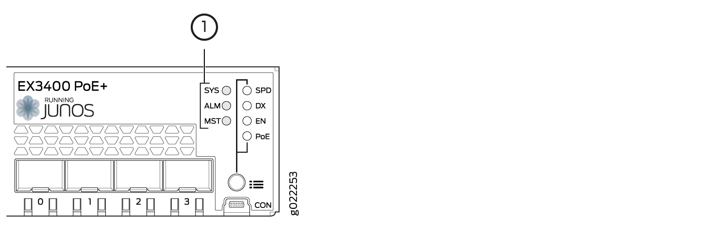
1 — Chassis Status LEDs |
Table 1 describes the chassis status LEDs in an EX3400 switch, their colors and states, and the status they indicate.
|
LED Label |
Color |
State and Description |
|---|---|---|
|
SYS |
Green |
|
|
ALM |
Red |
There is a major alarm. Note:
When you connect power to the switch, the alarm LED (ALM) glows red. This behavior is normal. Plugging an active Ethernet cable into the management port (MGMT) on the switch completes the network link and turns off the ALM LED. (See Connect a Device to a Network for Out-of-Band Management.) Connecting the switch to a dedicated management console instead of a network does not affect the ALM LED. The LED remains red until the switch is connected to a network. |
|
Yellow |
There is a minor alarm. Note:
The ALM LED glows yellow if you commit
a configuration to make it active on the switch without creating a
rescue configuration to back it up. To save the most recently committed
configuration as the rescue configuration, enter the operational mode
command |
|
|
Unlit |
There is no alarm or the switch is halted. |
|
|
MST |
Green |
In a standalone EX3400 switch:
In a Virtual Chassis configuration:
|
A major alarm (red) indicates a critical error condition that requires immediate action.
A minor alarm (yellow) indicates a noncritical condition that requires monitoring or maintenance. A minor alarm that is left unchecked might cause interruption in service or performance degradation.
All three LEDs can be lit simultaneously.
You can view the colors of the two LEDs remotely through the
CLI by issuing the operational mode command
            show
chassis led
.
See Also
Management Port LEDs in EX3400 Switches
The management port, which is on the rear panel of an EX3400 switch, has two LEDs that indicate link/activity and port status (see Figure 6).
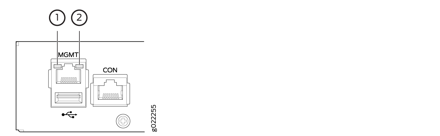
1 — Link/Activity LED | 2 — Status LED |
Table 2 describes the Link/Activity LED.
|
LED |
Color |
State and Description |
|---|---|---|
|
Link/Activity |
Green |
|
Table 3 describes the Status LED.
|
LED |
Color |
State and Description |
|---|---|---|
|
Status |
Green |
Indicates the speed. The speed indicators are:
|
See Also
RJ-45 Network Port and Uplink Port LEDs in EX3400 Switches
Each RJ-45 network port and the uplink port on an EX3400 switch have two LEDs each that indicate link/activity and port status. See Figure 7, Figure 8, and Figure 9.
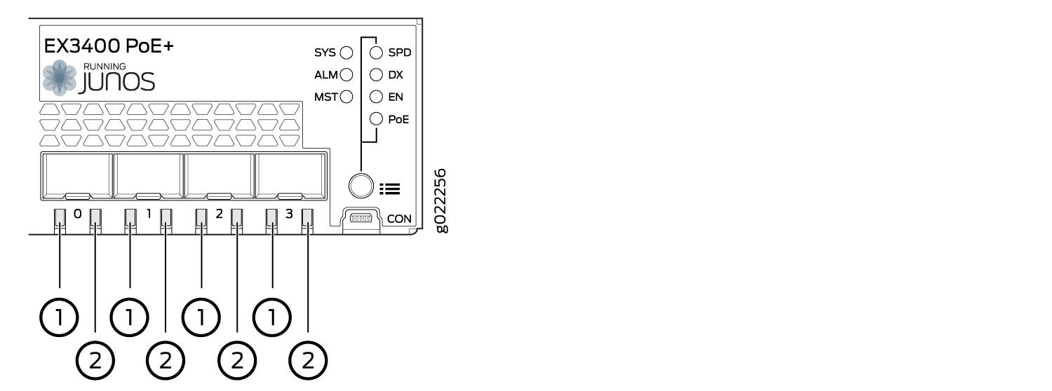
1 — Link/Activity LED on the SFP+ uplink ports | 2 — Status LED on the SFP+ uplink ports |
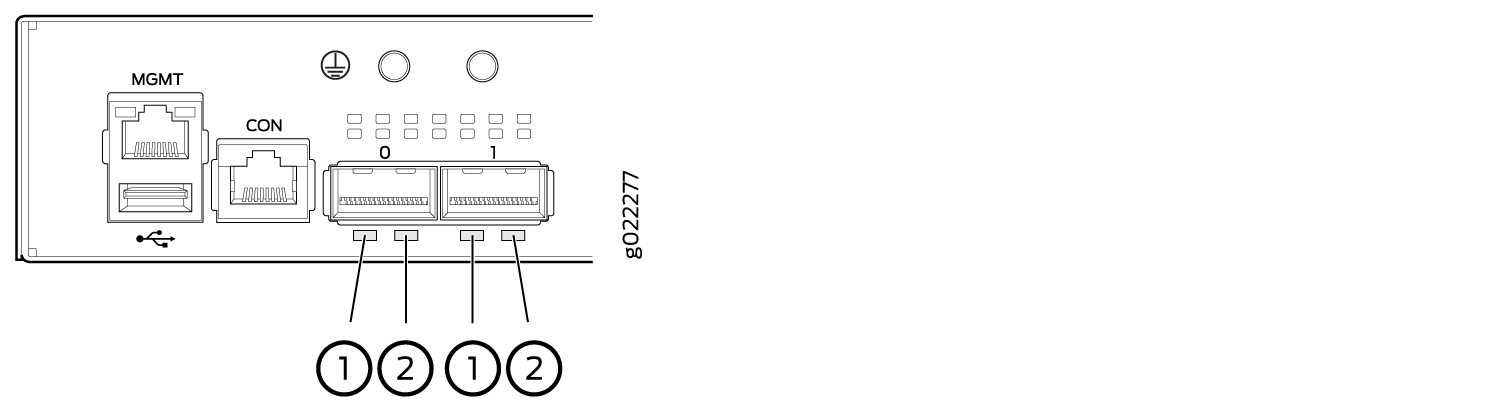
1 — Link/Activity LED on the QSFP+ uplink ports | 2 — Status LED on the QSFP+ uplink ports |
Table 4 describes the Link/Activity LED.
|
LED |
Color |
State and Description |
|---|---|---|
|
Link/Activity |
Green |
|
Figure 10 shows the LEDs that indicate the status of one of the four port parameters—speed, duplex mode, administrative status, and Power over Ethernet (PoE) status. Use the Factory Reset/Mode button on the far right side of the front panel to toggle the Status LED to show the different port parameters for RJ-45 network ports. You can tell which port parameter is indicated by the Status LED by looking at which port status mode LED (SPD, DX, EN, and PoE) is lit. The LED labeled PoE is not available on switch models with RJ-45 network ports that do not provide PoE.
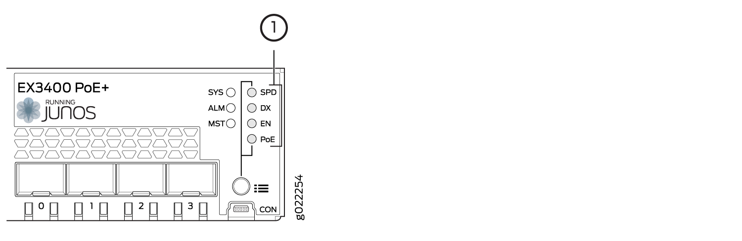
1 — Port mode LEDs |
Table 5 describes the Status LED on the RJ-45 network ports.
|
Port Parameters |
State and Description |
|---|---|
|
Speed (SPD) |
Indicates the speed. The speed indicators are:
|
|
Duplex mode (DX) |
Indicates the duplex mode. The status indicators are:
|
|
Administrative status (EN) |
Indicates the administrative status. The status indicators are:
|
|
PoE status (PoE) |
Indicates the PoE status. The status indicators for are:
Note:
PoE Status LED is available on the following EX3400 switch models:
|
Starting in Junos OS Release 19.4R1, you can use the
request chassis beacon
command
on EX3400 switches to identify the switch or a port on the switch.
When you execute the command, the status LEDs on the RJ-45 network
ports blink two times per second irrespective of the mode the ports
are operating in (see How to Locate a
Device or Port Using the Chassis Beacon).
The uplink ports operate in full-duplex mode and PoE is not applicable on uplink ports. The Status LED on uplink ports indicate the Speed (SPD) and Administrative status (EN). Table 6 describes the Status LED on the uplink ports.
|
Port Parameters |
State and Description |
|---|---|
|
Status LED |
Indicates the speed and administrative status.
|
You can tell which port parameter is indicated by the Status
LED on RJ-45 network ports and uplink ports by issuing the operational
mode command
show
chassis led
.