EN ESTA PÁGINA
Ejemplo: Tunelización de LDP a través de SR-TE en red OSPF
Descripción general
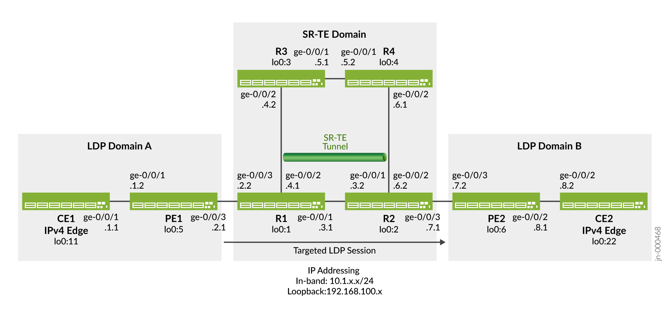
En este ejemplo se muestra cómo configurar la tunelización de LDP a través de SR-TE en una red OSPF. Esto se ilustra verificando que el túnel LDP a través de SR-TE esté habilitado y que el túnel LDP al dispositivo de borde remoto tome la ruta correcta. También muestra que la ruta al dispositivo de borde remoto usa el reenvío LDP y se tuneliza a través de SR-TE. En la siguiente topología (Figura 1), PE1 y PE2 son dispositivos de entrada y salida que admiten solo dispositivos IPv4 CE1 y CE2. Los dispositivos R1, R2, R3 y R4 comprenden una red central SR-TE solo IPv4. La topología muestra dos dominios LDP: El dominio LDP consta de los dispositivos CE1 y PE1; El dominio B de LDP consta de los dispositivos PE2 y CE2. Los dominios LDP están conectados a la red central de SR-TE, que extiende la sesión de LSP sobre el núcleo mediante un túnel a través de SR-TE.
Topología
Requisitos
En este ejemplo, se utilizan los siguientes componentes de hardware y software:
-
Enrutadores de la serie MX como enrutadores CE, PE y de núcleo.
-
Junos OS versión 22.4R1 o posterior ejecutándose en todos los dispositivos.
Configuración
Para tunelizar LDP LSP a través de SR-TE en su red principal, realice estas tareas:
Configuración rápida de CLI
Para configurar rápidamente este ejemplo, copie los siguientes comandos, péguelos en un archivo de texto, elimine los saltos de línea, cambie los detalles necesarios para que coincidan con su configuración de red, copie y pegue los comandos en la CLI en el nivel de jerarquía [edit] y, luego, ingrese commit desde el modo de configuración.
enhanced-ip'chassis' WARNING: Chassis configuration for network services has been changed. A system reboot is mandatory. Please reboot the system NOW. Continuing without a reboot might result in unexpected system behavior. commit complete
Dispositivo CE1
set chassis network-services enhanced-ip
set interfaces ge-0/0/1 description CE1-to-PE1
set interfaces ge-0/0/1 unit 0 family inet address 10.1.1.1/24
set interfaces lo0 unit 0 family inet address 192.168.100.11/32
set protocols ospf area 0.0.0.0 interface ge-0/0/1.0
set protocols ospf area 0.0.0.0 interface lo0.0 passive
set routing-options router-id 192.168.100.11
Dispositivo PE1
set chassis network-services enhanced-ip
set interfaces ge-0/0/1 description PE1-to-CE1
set interfaces ge-0/0/1 unit 0 family inet address 10.1.1.2/24
set interfaces ge-0/0/1 unit 0 family mpls maximum-labels 8
set interfaces ge-0/0/3 description PE1-to-R1
set interfaces ge-0/0/3 unit 0 family inet address 10.1.2.1/24
set interfaces ge-0/0/3 unit 0 family mpls maximum-labels 8
set interfaces lo0 unit 0 family inet address 192.168.100.5/32
set interfaces lo0 unit 0 family mpls
set policy-options policy-statement export_bgp term a from protocol bgp
set policy-options policy-statement export_bgp term a from protocol direct
set policy-options policy-statement export_bgp term a then accept
set routing-instances CE1_vpn1 instance-type vrf
set routing-instances CE1_vpn1 protocols ospf area 0.0.0.0 interface ge-0/0/1.0
set routing-instances CE1_vpn1 protocols ospf export export_bgp
set routing-instances CE1_vpn1 interface ge-0/0/1.0
set routing-instances CE1_vpn1 route-distinguisher 192.168.100.5:1
set routing-instances CE1_vpn1 vrf-target target:100:4
set routing-instances CE1_vpn1 vrf-table-label
set routing-options router-id 192.168.100.5
set routing-options autonomous-system 65410
set protocols bgp group ibgp1 type internal
set protocols bgp group ibgp1 local-address 192.168.100.5
set protocols bgp group ibgp1 family inet unicast
set protocols bgp group ibgp1 family inet-vpn unicast
set protocols bgp group ibgp1 neighbor 192.168.100.6
set protocols ldp interface ge-0/0/3.0
set protocols ldp interface lo0.0
set protocols mpls interface ge-0/0/3.0
set protocols ospf area 0.0.0.0 interface ge-0/0/3.0 point-to-point
set protocols ospf area 0.0.0.0 interface lo0.0 passive
Dispositivo R1
set chassis network-services enhanced-ip
set interfaces ge-0/0/1 description R1-to-R2
set interfaces ge-0/0/1 unit 0 family inet address 10.1.3.1/24
set interfaces ge-0/0/1 unit 0 family mpls maximum-labels 8
set interfaces ge-0/0/2 description R1-to-R3
set interfaces ge-0/0/2 unit 0 family inet address 10.1.4.1/24
set interfaces ge-0/0/2 unit 0 family mpls maximum-labels 8
set interfaces ge-0/0/3 description R1-to-PE1
set interfaces ge-0/0/3 unit 0 family inet address 10.1.2.2/24
set interfaces ge-0/0/3 unit 0 family mpls maximum-labels 8
set interfaces lo0 unit 0 family inet address 192.168.100.1/32
set interfaces lo0 unit 0 family mpls
set routing-options router-id 192.168.100.1
set protocols ldp auto-targeted-session
set protocols ldp preference 1
set protocols ldp interface ge-0/0/1.0
set protocols ldp interface ge-0/0/3.0
set protocols ldp interface lo0.0
set protocols mpls interface ge-0/0/1.0
set protocols mpls interface ge-0/0/2.0
set protocols mpls interface ge-0/0/3.0
set protocols ospf backup-spf-options use-post-convergence-lfa
set protocols ospf backup-spf-options use-source-packet-routing
set protocols ospf traffic-engineering l3-unicast-topology
set protocols ospf traffic-engineering credibility-protocol-preference
set protocols ospf traffic-engineering advertisement always
set protocols ospf traffic-engineering tunnel-source-protocol spring-te
set protocols ospf source-packet-routing node-segment ipv4-index 5001
set protocols ospf source-packet-routing srgb start-label 80000
set protocols ospf source-packet-routing srgb index-range 50000
set protocols ospf area 0.0.0.0 interface ge-0/0/1.0 point-to-point
set protocols ospf area 0.0.0.0 interface ge-0/0/1.0 post-convergence-lfa
set protocols ospf area 0.0.0.0 interface ge-0/0/1.0 ipv4-adjacency-segment protected index 108
set protocols ospf area 0.0.0.0 interface ge-0/0/1.0 ipv4-adjacency-segment unprotected index 110
set protocols ospf area 0.0.0.0 interface ge-0/0/2.0 point-to-point
set protocols ospf area 0.0.0.0 interface ge-0/0/2.0 post-convergence-lfa
set protocols ospf area 0.0.0.0 interface ge-0/0/2.0 ipv4-adjacency-segment protected index 104
set protocols ospf area 0.0.0.0 interface ge-0/0/2.0 ipv4-adjacency-segment unprotected index 106
set protocols ospf area 0.0.0.0 interface ge-0/0/3.0 point-to-point
set protocols ospf area 0.0.0.0 interface ge-0/0/3.0 post-convergence-lfa
set protocols ospf area 0.0.0.0 interface ge-0/0/3.0 ipv4-adjacency-segment protected index 100
set protocols ospf area 0.0.0.0 interface ge-0/0/3.0 ipv4-adjacency-segment unprotected index 102
set protocols ospf area 0.0.0.0 interface lo0.0 passive
set protocols source-packet-routing segment-list seg1 inherit-label-nexthops
set protocols source-packet-routing segment-list seg1 auto-translate
set protocols source-packet-routing segment-list seg1 hop1 ip-address 10.1.4.2
set protocols source-packet-routing segment-list seg1 hop2 ip-address 10.1.5.2
set protocols source-packet-routing segment-list seg1 hop3 ip-address 10.1.6.2
set protocols source-packet-routing source-routing-path sr_static_r5 ldp-tunneling
set protocols source-packet-routing source-routing-path sr_static_r5 to 192.168.100.2
set protocols source-packet-routing source-routing-path sr_static_r5 binding-sid 1003001
set protocols source-packet-routing source-routing-path sr_static_r5 primary seg1
Dispositivo R2
set chassis network-services enhanced-ip
set interfaces ge-0/0/1 description R2-to-R1
set interfaces ge-0/0/1 unit 0 family inet address 10.1.3.2/24
set interfaces ge-0/0/1 unit 0 family mpls maximum-labels 8
set interfaces ge-0/0/2 description R2-to-R4
set interfaces ge-0/0/2 unit 0 family inet address 10.1.6.2/24
set interfaces ge-0/0/2 unit 0 family mpls maximum-labels 8
set interfaces ge-0/0/3 description R2-to-PE2
set interfaces ge-0/0/3 unit 0 family inet address 10.1.7.1/24
set interfaces ge-0/0/3 unit 0 family mpls maximum-labels 8
set interfaces lo0 unit 0 family inet address 192.168.100.2/32
set interfaces lo0 unit 0 family mpls
set routing-options router-id 192.168.100.2
set protocols ldp auto-targeted-session
set protocols ldp preference 1
set protocols ldp interface ge-0/0/1.0
set protocols ldp interface ge-0/0/3.0
set protocols ldp interface lo0.0
set protocols mpls interface ge-0/0/1.0
set protocols mpls interface ge-0/0/2.0
set protocols mpls interface ge-0/0/3.0
set protocols ospf backup-spf-options use-post-convergence-lfa
set protocols ospf backup-spf-options use-source-packet-routing
set protocols ospf traffic-engineering l3-unicast-topology
set protocols ospf traffic-engineering credibility-protocol-preference
set protocols ospf traffic-engineering advertisement always
set protocols ospf traffic-engineering tunnel-source-protocol spring-te
set protocols ospf source-packet-routing node-segment ipv4-index 5002
set protocols ospf source-packet-routing srgb start-label 80000
set protocols ospf source-packet-routing srgb index-range 50000
set protocols ospf area 0.0.0.0 interface ge-0/0/1.0 point-to-point
set protocols ospf area 0.0.0.0 interface ge-0/0/1.0 post-convergence-lfa
set protocols ospf area 0.0.0.0 interface ge-0/0/1.0 ipv4-adjacency-segment protected index 500
set protocols ospf area 0.0.0.0 interface ge-0/0/1.0 ipv4-adjacency-segment unprotected index 502
set protocols ospf area 0.0.0.0 interface ge-0/0/2.0 point-to-point
set protocols ospf area 0.0.0.0 interface ge-0/0/2.0 post-convergence-lfa
set protocols ospf area 0.0.0.0 interface ge-0/0/2.0 ipv4-adjacency-segment protected index 504
set protocols ospf area 0.0.0.0 interface ge-0/0/2.0 ipv4-adjacency-segment unprotected index 506
set protocols ospf area 0.0.0.0 interface ge-0/0/3.0 point-to-point
set protocols ospf area 0.0.0.0 interface ge-0/0/3.0 post-convergence-lfa
set protocols ospf area 0.0.0.0 interface ge-0/0/3.0 ipv4-adjacency-segment protected index 508
set protocols ospf area 0.0.0.0 interface ge-0/0/3.0 ipv4-adjacency-segment unprotected index 510
set protocols ospf area 0.0.0.0 interface lo0.0 passive
set protocols source-packet-routing segment-list seg1 inherit-label-nexthops
set protocols source-packet-routing segment-list seg1 auto-translate
set protocols source-packet-routing segment-list seg1 hop1 ip-address 10.1.6.1
set protocols source-packet-routing segment-list seg1 hop2 ip-address 10.1.5.1
set protocols source-packet-routing segment-list seg1 hop3 ip-address 10.1.4.1
set protocols source-packet-routing source-routing-path sr_static_r1 ldp-tunneling
set protocols source-packet-routing source-routing-path sr_static_r1 to 192.168.100.1
set protocols source-packet-routing source-routing-path sr_static_r1 binding-sid 1003001
set protocols source-packet-routing source-routing-path sr_static_r1 primary seg1
Dispositivo R3
set chassis network-services enhanced-ip
set interfaces ge-0/0/1 description R3-to-R4
set interfaces ge-0/0/1 unit 0 family inet address 10.1.5.1/24
set interfaces ge-0/0/1 unit 0 family mpls
set interfaces ge-0/0/2 description R3-to-R1
set interfaces ge-0/0/2 unit 0 family inet address 10.1.4.2/24
set interfaces ge-0/0/2 unit 0 family mpls
set interfaces lo0 unit 0 family inet address 192.168.100.3/32
set interfaces lo0 unit 0 family mpls
set routing-options router-id 192.168.100.3
set protocols mpls interface ge-0/0/1.0
set protocols mpls interface ge-0/0/2.0
set protocols ospf backup-spf-options use-post-convergence-lfa
set protocols ospf backup-spf-options use-source-packet-routing
set protocols ospf traffic-engineering l3-unicast-topology
set protocols ospf traffic-engineering credibility-protocol-preference
set protocols ospf traffic-engineering advertisement always
set protocols ospf source-packet-routing node-segment ipv4-index 5003
set protocols ospf source-packet-routing srgb start-label 80000
set protocols ospf source-packet-routing srgb index-range 50000
set protocols ospf area 0.0.0.0 interface ge-0/0/1.0 point-to-point
set protocols ospf area 0.0.0.0 interface ge-0/0/1.0 post-convergence-lfa
set protocols ospf area 0.0.0.0 interface ge-0/0/1.0 ipv4-adjacency-segment protected index 204
set protocols ospf area 0.0.0.0 interface ge-0/0/1.0 ipv4-adjacency-segment unprotected index 206
set protocols ospf area 0.0.0.0 interface ge-0/0/2.0 point-to-point
set protocols ospf area 0.0.0.0 interface ge-0/0/2.0 post-convergence-lfa
set protocols ospf area 0.0.0.0 interface ge-0/0/2.0 ipv4-adjacency-segment protected index 200
set protocols ospf area 0.0.0.0 interface ge-0/0/2.0 ipv4-adjacency-segment unprotected index 202
set protocols ospf area 0.0.0.0 interface lo0.0 passive
Dispositivo R4
set chassis network-services enhanced-ip
set interfaces ge-0/0/1 description R4-to-R3
set interfaces ge-0/0/1 unit 0 family inet address 10.1.5.2/24
set interfaces ge-0/0/1 unit 0 family mpls
set interfaces ge-0/0/2 description R4-to-R2
set interfaces ge-0/0/2 unit 0 family inet address 10.1.6.1/24
set interfaces ge-0/0/2 unit 0 family mpls
set interfaces lo0 unit 0 family inet address 192.168.100.4/32
set interfaces lo0 unit 0 family mpls
set routing-options router-id 192.168.100.4
set protocols mpls interface ge-0/0/1.0
set protocols mpls interface ge-0/0/2.0
set protocols ospf backup-spf-options use-post-convergence-lfa
set protocols ospf backup-spf-options use-source-packet-routing
set protocols ospf traffic-engineering l3-unicast-topology
set protocols ospf traffic-engineering credibility-protocol-preference
set protocols ospf traffic-engineering advertisement always
set protocols ospf source-packet-routing node-segment ipv4-index 5004
set protocols ospf source-packet-routing srgb start-label 80000
set protocols ospf source-packet-routing srgb index-range 50000
set protocols ospf area 0.0.0.0 interface ge-0/0/1.0 point-to-point
set protocols ospf area 0.0.0.0 interface ge-0/0/1.0 post-convergence-lfa
set protocols ospf area 0.0.0.0 interface ge-0/0/1.0 ipv4-adjacency-segment protected index 300
set protocols ospf area 0.0.0.0 interface ge-0/0/1.0 ipv4-adjacency-segment unprotected index 302
set protocols ospf area 0.0.0.0 interface ge-0/0/2.0 point-to-point
set protocols ospf area 0.0.0.0 interface ge-0/0/2.0 post-convergence-lfa
set protocols ospf area 0.0.0.0 interface ge-0/0/2.0 ipv4-adjacency-segment protected index 304
set protocols ospf area 0.0.0.0 interface ge-0/0/2.0 ipv4-adjacency-segment unprotected index 306
set protocols ospf area 0.0.0.0 interface lo0.0 passive
Dispositivo PE2
set chassis network-services enhanced-ip
set interfaces ge-0/0/2 description PE2-to-CE2
set interfaces ge-0/0/2 unit 0 family inet address 10.1.8.1/24
set interfaces ge-0/0/2 unit 0 family mpls maximum-labels 8
set interfaces ge-0/0/3 description PE2-to-R2
set interfaces ge-0/0/3 unit 0 family inet address 10.1.7.2/24
set interfaces ge-0/0/3 unit 0 family mpls maximum-labels 8
set interfaces lo0 unit 0 family inet address 192.168.100.6/32
set interfaces lo0 unit 0 family mpls
set policy-options policy-statement export_bgp term a from protocol bgp
set policy-options policy-statement export_bgp term a from protocol direct
set policy-options policy-statement export_bgp term a then accept
set routing-instances CE2_vpn1 instance-type vrf
set routing-instances CE2_vpn1 protocols ospf area 0.0.0.0 interface ge-0/0/2.0
set routing-instances CE2_vpn1 protocols ospf export export_bgp
set routing-instances CE2_vpn1 interface ge-0/0/2.0
set routing-instances CE2_vpn1 route-distinguisher 192.168.100.6:1
set routing-instances CE2_vpn1 vrf-target target:100:4
set routing-instances CE2_vpn1 vrf-table-label
set routing-options router-id 192.168.100.6
set routing-options autonomous-system 65410
set protocols bgp group ibgp1 type internal
set protocols bgp group ibgp1 local-address 192.168.100.6
set protocols bgp group ibgp1 family inet unicast
set protocols bgp group ibgp1 family inet-vpn unicast
set protocols bgp group ibgp1 neighbor 192.168.100.5
set protocols ldp interface ge-0/0/3.0
set protocols ldp interface lo0.0
set protocols mpls interface ge-0/0/3.0
set protocols ospf area 0.0.0.0 interface ge-0/0/3.0 point-to-point
set protocols ospf area 0.0.0.0 interface lo0.0 passive
Dispositivo CE2
set chassis network-services enhanced-ip
set interfaces ge-0/0/1 description CE2-to-PE2
set interfaces ge-0/0/2 unit 0 family inet address 10.1.8.2/24
set interfaces lo0 unit 0 family inet address 192.168.100.22/32
set protocols ospf area 0.0.0.0 interface ge-0/0/2.0
set protocols ospf area 0.0.0.0 interface lo0.0 passive
set routing-options router-id 192.168.100.22
Configuración de PE1
Procedimiento paso a paso
En el ejemplo siguiente, debe explorar por varios niveles en la jerarquía de configuración. Para obtener información acerca de cómo navegar por la CLI, consulte Uso del editor de CLI en modo de configuración en la Guía del usuario de CLI.https://www.juniper.net/documentation/en_US/junos/topics/reference/general/cli-editor-configuration-mode-quick-reference-using.htmlhttps://www.juniper.net/documentation/en_US/junos/information-products/pathway-pages/junos-cli/junos-cli.html
Para configurar el dispositivo PE1:
-
Configure el modo de servicios de red como IP mejorada. IP mejorada establece los servicios de red del enrutador en Protocolo de Internet mejorado y utiliza capacidades de modo mejorado.
[edit chassis]
user@PE1#set network-services enhanced-ip
-
Configure las interfaces del dispositivo.
[edit interfaces]
user@PE1#set ge-0/0/1 description PE1-to-CE1
user@PE1#set ge-0/0/1 unit 0 family inet address 10.1.1.2/24
user@PE1#set ge-0/0/3 description PE1-to-R1
user@PE1#set ge-0/0/3 unit 0 family inet address 10.1.2.1/24
user@PE1#set ge-0/0/3 unit 0 family mpls
user@PE1#set lo0 unit 0 family inet address 192.168.100.5/32
user@PE1#set lo0 unit 0 family mpls
-
Configure las opciones de directiva para exportar rutas BGP al enrutador CE, que ejecuta el protocolo OSPF en este ejemplo.
[edit policy-options]
user@PE1#set policy-statement export_bgp term a from protocol bgp
user@PE1#set policy-statement export_bgp term a from protocol direct
user@PE1#set policy-statement export_bgp term a then accept
-
Configure una instancia de enrutamiento VPN de capa 3 para admitir el dispositivo CE1 basado en OSPF.
[edit routing-instances]
user@PE1#set CE1_vpn1 instance-type vrf
user@PE1#set CE1_vpn1 protocols ospf area 0.0.0.0 interface ge-0/0/1.0
user@PE1#set CE1_vpn1 protocols ospf export export_bgp
user@PE1#set CE1_vpn1 interface ge-0/0/1.0
user@PE1#set CE1_vpn1 route-distinguisher 192.168.100.5:1
user@PE1#set CE1_vpn1 vrf-target target:100:4
user@PE1#set CE1_vpn1 vrf-table-label
-
Configure el ID del enrutador y el número de sistema autónomo para el dispositivo PE1.
[edit routing-options]
user@PE1#set router-id 192.168.100.5
userPE1# set autonomous-system 65410
-
Configure OSPF, LDP y MPLS en las interfaces conectadas a la red principal.
[edit protocols]
user@PE1#set ospf area 0.0.0.0 interface ge-0/0/3.0 point-to-point
user@PE1#set ospf area 0.0.0.0 lo0.0 passive
user@PE1#set ldp interface ge-0/0/3.0
user@PE1#set ldp interface lo0.0
user@PE1#set mpls interface ge-0/0/3.0
user@PE1#set mpls interface lo0.0
-
Configure BGP entre los dispositivos PE.
[edit protocols]
user@PE1#set bgp group ibgp1 type internal
user@PE1#set bgp group ibgp1 local-address 192.168.100.5
user@PE1#set bgp group ibgp1 family inet unicast
user@PE1#set bgp group ibgp1 family inet-vpn unicast
user@PE1#set bgp group ibgp1 neighbor 192.168.100.6
Resultados
Desde el modo de configuración, escriba los comandos , , , , y para confirmar la configuración.show chassisshow interfacesshow policy-optionsshow routing-instancesshow routing-optionsshow protocols Si el resultado no muestra la configuración deseada, repita las instrucciones en este ejemplo para corregir la configuración.
user@PE1#show chassis
network-services enhanced-ip;
user@PE1#show interfaces
ge-0/0/1 {
    description PE1-to-CE1;
    unit 0 {
        family inet {
            address 10.1.1.2/24;
        }
        family mpls {
            maximum-labels 8;
        }
    }
}
ge-0/0/3 {
    description PE1-to-R1;
    unit 0 {
        family inet {
            address 10.1.2.1/24;
        }
        family mpls {
            maximum-labels 8;
        }
    }
}
lo0 {
    unit 0 {
        family inet {
            address 192.168.100.5/32;
        }
        family mpls;
    }
}
user@PE1#show policy-options
policy-statement export_bgp {
    term a {
        from protocol [ bgp direct ];
        then accept;
    }
}
user@PE1#show routing-instances
CE1_vpn1 {
    instance-type vrf;
    protocols {
        ospf {
            area 0.0.0.0 {
                interface ge-0/0/1.0;
            }
            export export_bgp;
        }
    }
    interface ge-0/0/1.0;
    route-distinguisher 192.168.100.5:1;
    vrf-target target:100:4;
    vrf-table-label;
}
user@PE1#show routing-options
router-id 192.168.100.5;
autonomous-system 65410;
user@PE1#show protocols
bgp {
    group ibgp1 {
        type internal;
        local-address 192.168.100.5;
        family inet {
            unicast;
        }
        family inet-vpn {
            unicast;
        }
        neighbor 192.168.100.6;
    }
}
ldp {
    interface ge-0/0/3.0;
    interface lo0.0;
}
mpls {
    interface ge-0/0/3.0;
    interface lo0.0;
}
ospf {
    area 0.0.0.0 {
        interface ge-0/0/3.0 {
            point-to-point;
        }
        interface lo0.0 {
            passive;
        }
    }
}
Configuración del dispositivo R1
Procedimiento paso a paso
En el ejemplo siguiente, debe explorar por varios niveles en la jerarquía de configuración. Para obtener información acerca de cómo navegar por la CLI, consulte Uso del editor de CLI en modo de configuración en la Guía del usuario de CLI.https://www.juniper.net/documentation/en_US/junos/topics/reference/general/cli-editor-configuration-mode-quick-reference-using.htmlhttps://www.juniper.net/documentation/en_US/junos/information-products/pathway-pages/junos-cli/junos-cli.html
Para configurar el dispositivo R1:
-
Configure el modo de servicios de red como IP mejorada. IP mejorada establece los servicios de red del enrutador en Protocolo de Internet mejorado y utiliza capacidades de modo mejorado.
[edit chassis]
user@R1#set network-services enhanced-ip
Después de configurar la instrucción y confirmar la configuración, aparece el siguiente mensaje de advertencia solicitándole que reinicie el enrutador:
enhanced-ip'chassis' WARNING: Chassis configuration for network services has been changed. A system reboot is mandatory. Please reboot the system NOW. Continuing without a reboot might result in unexpected system behavior. commit complete
El reinicio abre los FPC en el enrutador.
-
Configure las interfaces del dispositivo.
[edit interfaces]
user@R1#set ge-0/0/1 description R1-to-R2
user@R1#set ge-0/0/1 unit 0 family inet address 10.1.3.1/24
user@R1#set ge-0/0/1 unit 0 family mpls maximum-labels 8
user@R1#set ge-0/0/2 description R1-to-R3
user@R1#set ge-0/0/2 unit 0 family inet address 10.1.4.1/24
user@R1#set ge-0/0/2 unit 0 family mpls maximum-labels 8
user@R1#set ge-0/0/3 description R1-to-PE1
user@R1#set ge-0/0/3 unit 0 family inet address 10.1.2.2/24
user@R1#set ge-0/0/3 unit 0 family mpls maximum-labels 8
user@R1#set lo0 unit 0 family inet address 192.168.100.1/32
user@R1#set lo0 unit 0 family mpls
-
Configure las opciones de enrutamiento para identificar el enrutador en el dominio.
[edit routing-options]
user@R1#set router-id 192.168.100.1
-
Configure SID de adyacencia OSPF en las interfaces y asigne etiquetas SRGB para habilitar el enrutamiento de segmentos. Las etiquetas de todo el SRGB están disponibles para OSPF. Los SID de prefijo (y los SID de nodo) se indexan desde el SRGB.
[edit protocols]
user@R1#set ospf area 0.0.0.0 interface ge-0/0/1.0 ipv4-adjacency-segment protected index 108
user@R1#set ospf area 0.0.0.0 interface ge-0/0/1.0 ipv4-adjacency-segment unprotected index 110
user@R1#set ospf area 0.0.0.0 interface ge-0/0/1.0 post-convergence-lfa
user@R1#set ospf area 0.0.0.0 interface ge-0/0/1.0 point-to-point
user@R1#set ospf area 0.0.0.0 interface ge-0/0/2.0 ipv4-adjacency-segment protected index 104
user@R1#set ospf area 0.0.0.0 interface ge-0/0/2.0 ipv4-adjacency-segment unprotected index 106
user@R1#set ospf area 0.0.0.0 interface ge-0/0/2.0 post-convergence-lfa
user@R1#set ospf area 0.0.0.0 interface ge-0/0/2.0 point-to-point
user@R1#set ospf area 0.0.0.0 interface ge-0/0/3.0 ipv4-adjacency-segment protected index 100
user@R1#set ospf area 0.0.0.0 interface ge-0/0/3.0 ipv4-adjacency-segment unprotected index 102
user@R1#set ospf area 0.0.0.0 interface ge-0/0/3.0 post-convergence-lfa
user@R1#set ospf area 0.0.0.0 interface ge-0/0/3.0 point-to-point
user@R1#set ospf area 0.0.0.0 interface lo0.0 passive
user@R1#set ospf source-packet-routing srgb start-label 80000
user@R1#set ospf source-packet-routing srgb index-range 50000
user@R1#set ospf source-packet-routing node-segment ipv4-index 5001
-
Configure TI-LFA para habilitar la protección contra fallas de vínculos y nodos. El SR que usa TI-LFA proporciona una restauración más rápida de la conectividad de red al enrutar el tráfico instantáneamente a una copia de seguridad o una ruta alternativa si la ruta principal falla o no está disponible.
[edit protocols]
user@R1#set ospf backup-spf-options use-post-convergence-lfa
user@R1#set ospf backup-spf-options use-source-packet-routing
-
Configure los parámetros de ingeniería de tráfico de OSPF.
[edit protocols]
user@R1#set ospf traffic-engineering l3-unicast-topology
user@R1#set ospf traffic-engineering credibility-protocol-preference
user@R1#set protocols ospf traffic-engineering advertisement always
-
Habilite la tunelización de LDP a través de SR-TE.
[edit protocols]
user@R1#set ospf traffic-engineering tunnel-source-protocol spring-te
-
Configure los protocolos MPLS y LDP en las interfaces del dominio LDP para intercambiar etiquetas en el dominio LDP.
[edit protocols]
user@R1#set ldp preference 1
user@R1#set protocols ldp interface ge-0/0/1.0
user@R1#set ldp interface ge-0/0/3.0
user@R1#set ldp interface lo0.0
user@R1#set mpls interface ge-0/0/1.0
user@R1#set mpls interface ge-0/0/2.0
user@R1#set mpls interface ge-0/0/3.0
user@R1#set mpls interface lo0.0
-
Habilite la sesión LDP dirigida entre los enrutadores perimetrales del dominio LDP.
[edit protocols]
user@R1#set ldp auto-targeted-session
-
Configure una lista de segmentos para enrutar el tráfico a una ruta específica.
[edit protocols]
user@R1#set source-packet-routing segment-list seg1 inherit-label-nexthops
user@R1#set source-packet-routing segment-list seg1 auto-translate
user@R1#set source-packet-routing segment-list seg1 hop1 ip-address 192.168.4.2
user@R1#set source-packet-routing segment-list seg1 hop2 ip-address 192.168.5.2
user@R1#set source-packet-routing segment-list seg1 hop3 ip-address 192.168.6.2
-
Configure LSP SR-TE en los enrutadores perimetrales remotos para habilitar la tunelización LDP a través de SR-TE.
[edit protocols]
user@R1#set source-packet-routing source-routing-path sr_static_r5 ldp-tunneling
user@R1#set source-packet-routing source-routing-path sr_static_r5 to 192.168.66.66
user@R1#set source-packet-routing source-routing-path sr_static_r5 binding-sid 1003001
user@R1#set source-packet-routing source-routing-path sr_static_r5 primary seg1
Resultados
Desde el modo de configuración, ingrese los comandos show chassis, show interfaces, show routing-options y show protocols para confirmar la configuración. Si el resultado no muestra la configuración deseada, repita las instrucciones en este ejemplo para corregir la configuración.
user@R1#show chassis
network-services enhanced-ip;
user@R1#show interfaces
ge-0/0/1 {
    description R1-to-R2;
    unit 0 {
        family inet {
            address 10.1.3.1/24;
        }
        family mpls {
            maximum-labels 8;
        }
    }
}
ge-0/0/2 {
    description R1-to-R3;
    unit 0 {
        family inet {
            address 10.1.4.1/24;
        }
        family mpls {
            maximum-labels 8;
        }
    }
}
ge-0/0/3 {
    description R1-to-PE1;
    unit 0 {
        family inet {
            address 10.1.2.2/24;
        }
        family mpls {
            maximum-labels 8;
        }
    }
}
lo0 {
    unit 0 {
        family inet {
            address 192.168.100.1/32;
        }
        family mpls;
    }
}
user@R1#show protocols
ldp {
    auto-targeted-session;
    preference 1;
    interface ge-0/0/1.0;
    interface ge-0/0/3.0;
    interface lo0.0;
}
mpls {
    interface ge-0/0/1.0;
    interface ge-0/0/2.0;
    interface ge-0/0/3.0;
    interface lo0.0;
}
ospf {
    backup-spf-options {
        use-post-convergence-lfa;
        use-source-packet-routing;
    }
    traffic-engineering {
        l3-unicast-topology;
        credibility-protocol-preference;
        advertisement always;
        tunnel-source-protocol {
            spring-te;
        }
    }
    source-packet-routing {
        node-segment ipv4-index 5001;
        srgb start-label 80000 index-range 50000;
    }
    area 0.0.0.0 {
        interface ge-0/0/1.0 {
            point-to-point;
            post-convergence-lfa;
            ipv4-adjacency-segment {
                protected index 108;
                unprotected index 110;
            }
        }
        interface ge-0/0/2.0 {
            point-to-point;
            post-convergence-lfa;
            ipv4-adjacency-segment {
                protected index 104;
                unprotected index 106;
            }
        }
        interface ge-0/0/3.0 {
            point-to-point;
            post-convergence-lfa;
            ipv4-adjacency-segment {
                protected index 100;
                unprotected index 102;
            }
        }
        interface lo0.0 {
            passive;
        }
    }
}
source-packet-routing {
    segment-list seg1 {
        inherit-label-nexthops;
        auto-translate;
        hop1 ip-address 10.1.4.2;
        hop2 ip-address 10.1.5.2;
        hop3 ip-address 10.1.6.2;
    }
    source-routing-path sr_static_r5 {
        ldp-tunneling;
        to 192.168.100.2;
        binding-sid 1003001;
        primary {
            seg1;
        }
    }
}
user@R1#show routing-options
router-id 192.168.100.1;
Verificación
Para confirmar que la configuración funciona correctamente, realice las siguientes tareas:
- Verificación de la tunelización de LDP a través de SR-TE
- Verificación de la etiqueta anunciada
- Comprobar el reenvío de LDP al dispositivo de PE remoto
- Verificar la accesibilidad de extremo a extremo
Verificación de la tunelización de LDP a través de SR-TE
Propósito
Compruebe que el túnel LDP a través de SR-TE esté habilitado y que el túnel LDP al enrutador de borde remoto esté tomando la ruta correcta.
Acción
Desde el modo operativo, ejecute el comando.show spring-traffic-engineering lsp detail
En R1
user@R1>show spring-traffic-engineering lsp detail
Name: sr_static_r5
  Tunnel-source: Static configuration
  Tunnel Forward Type: SRMPLS
  To: 192.168.100.2
  Te-group-id: 0
  State: Up
  LDP-tunneling enabled
    Path: seg1
    Path Status: NA
    Outgoing interface: NA
    Auto-translate status: Enabled Auto-translate result: Success
    Compute Status:Disabled , Compute Result:N/A , Compute-Profile Name:N/A
    BFD status: N/A BFD name: N/A
    BFD remote-discriminator: N/A
    Segment ID : 128
    ERO Valid: true
      SR-ERO hop count: 3
        Hop 1 (Strict):
          NAI: IPv4 Adjacency ID, 0.0.0.0 -> 10.1.4.2
          SID type: 20-bit label, Value: 80104
        Hop 2 (Strict):
          NAI: IPv4 Adjacency ID, 0.0.0.0 -> 10.1.5.2
          SID type: 20-bit label, Value: 80204
        Hop 3 (Strict):
          NAI: IPv4 Adjacency ID, 0.0.0.0 -> 10.1.6.2
          SID type: 20-bit label, Value: 80304

Total displayed LSPs: 1 (Up: 1, Down: 0)
En R2
user@R2>show spring-traffic-engineering lsp detail
Name: sr_static_r1
  Tunnel-source: Static configuration
  Tunnel Forward Type: SRMPLS
  To: 192.168.100.1
  Te-group-id: 0
  State: Up
  LDP-tunneling enabled
    Path: seg1
    Path Status: NA
    Outgoing interface: NA
    Auto-translate status: Enabled Auto-translate result: Success
    Compute Status:Disabled , Compute Result:N/A , Compute-Profile Name:N/A
    BFD status: N/A BFD name: N/A
    BFD remote-discriminator: N/A
    Segment ID : 128
    ERO Valid: true
      SR-ERO hop count: 3
        Hop 1 (Strict):
          NAI: IPv4 Adjacency ID, 0.0.0.0 -> 10.1.6.1
          SID type: 20-bit label, Value: 80504
        Hop 2 (Strict):
          NAI: IPv4 Adjacency ID, 0.0.0.0 -> 10.1.5.1
          SID type: 20-bit label, Value: 80300
        Hop 3 (Strict):
          NAI: IPv4 Adjacency ID, 0.0.0.0 -> 10.1.4.1
          SID type: 20-bit label, Value: 80200


Total displayed LSPs: 1 (Up: 1, Down: 0)
Significado
-
En R1, el túnel LDP se establece con el enrutador perimetral remoto en la red central de SR-TE.192.168.100.2 También puede ver los valores de la etiqueta SID en la salida.80104, 80204, 80304
-
En R2, el túnel LDP se establece con el enrutador perimetral remoto en la red central de SR-TE.192.168.100.1 También puede ver los valores de la etiqueta SID en la salida.80504, 80300, 80200
Verificación de la etiqueta anunciada
Propósito
Compruebe las etiquetas anunciadas para la clase de equivalencia de reenvío (FEC).
Acción
Desde el modo operativo, ejecute el comando.show ldp database
En R1
Verifique las etiquetas anunciadas para el PE conectado directamente (PE1) y las etiquetas recibidas del enrutador de borde remoto (R2).
user@R1>show ldp database

Input label database, 192.168.100.1:0--192.168.100.2:0
Labels received: 4
  Label     Prefix
     18      192.168.100.1/32
      3      192.168.100.2/32
     20      192.168.100.5/32
     16      192.168.100.6/32


Output label database, 192.168.100.1:0--192.168.100.2:0
Labels advertised: 4
  Label     Prefix
      3      192.168.100.1/32
     4115    192.168.100.2/32
     4114    192.168.100.5/32
     4117      192.168.100.6/32

Input label database, 192.168.100.1:0--192.168.100.5:0
Labels received: 4
  Label     Prefix
     17      192.168.100.1/32
     22      192.168.100.2/32
      3      192.168.100.5/32
     24      192.168.100.6/32

Output label database, 192.168.100.1:0--192.168.100.5:0
Labels advertised: 4
  Label     Prefix
      3      192.168.100.1/32
     4115    192.168.100.2/32
     4114    192.168.100.5/32
     4117      192.168.100.6/32
En R2
Verifique las etiquetas anunciadas para el PE conectado directamente (PE2) y las etiquetas recibidas del enrutador de borde remoto (R1).
user@R2>show ldp database

Input label database, 192.168.100.2:0--192.168.100.1:0
Labels received: 4
  Label     Prefix
      3      192.168.100.1/32
     4115    192.168.100.2/32
     4114    192.168.100.5/32
     4117    192.168.100.6/32

Output label database, 192.168.100.2:0--192.168.100.1:0
Labels advertised: 4
  Label     Prefix
     18      192.168.100.1/32
      3      192.168.100.2/32
     20      192.168.100.5/32
     16      192.168.100.6/32

Input label database, 192.168.100.2:0--192.168.100.6:0
Labels received: 4
  Label     Prefix
     24      192.168.100.1/32
     17      192.168.100.2/32
     25      192.168.100.5/32
      3      192.168.100.6/32

Output label database, 192.168.100.2:0--192.168.100.6:0
Labels advertised: 4
  Label     Prefix
     18      192.168.100.1/32
      3      192.168.100.2/32
     20      192.168.100.5/32
     16      192.168.100.6/32
En PE1
Compruebe que el dispositivo perimetral R1 anuncia la etiqueta de la dirección de circuito cerrado del dispositivo de PE remoto (PE2) en el dispositivo de PE local (PE1).
user@PE1>show ldp database

Input label database, 192.168.100.5:0--192.168.100.1:0
Labels received: 4
  Label     Prefix
      3      192.168.100.1/32
     4115    192.168.100.2/32
     4114    192.168.100.5/32
     4117      192.168.100.6/32

Output label database, 192.168.100.5:0--192.168.100.1:0
Labels advertised: 4
  Label     Prefix
     17      192.168.100.1/32
     22      192.168.100.2/32
      3      192.168.100.5/32
     24      192.168.100.6/32
En PE2
Compruebe que el dispositivo perimetral R2 anuncia la etiqueta de la dirección de circuito cerrado del dispositivo PE remoto (PE1) al dispositivo PE local (PE2).
user@PE2>show ldp database

Input label database, 192.168.100.6:0--192.168.100.2:0
Labels received: 4
  Label     Prefix
     18      192.168.100.1/32
      3      192.168.100.2/32
     20      192.168.100.5/32
     16      192.168.100.6/32

Output label database, 192.168.100.6:0--192.168.100.2:0
Labels advertised: 4
  Label     Prefix
     24      192.168.100.1/32
     17      192.168.100.2/32
     25      192.168.100.5/32
      3      192.168.100.6/32
Significado
-
En R1, puede ver que la etiqueta se anuncia hacia el PE conectado directamente (PE1) y la etiqueta se recibe del enrutador de borde remoto (R2).411727
-
En R2, puede ver que la etiqueta se anuncia hacia el PE conectado directamente (PE2) y la etiqueta se recibe del enrutador de borde remoto (R1).1825
-
En PE1, puede ver que la etiqueta se recibe del enrutador perimetral local (R1).4117
-
En PE2, puede ver que la etiqueta se recibe del enrutador perimetral local (R2).18
Comprobar el reenvío de LDP al dispositivo de PE remoto
Propósito
Verifique que la ruta al enrutador de PE remoto use el reenvío LDP y esté tunelizada a través de SR-TE.
Acción
Desde el modo operativo, ejecute el comando.show route destination-prefix
En R1
Compruebe que la ruta al enrutador PE () remoto se realiza a través de LDP a través del túnel SR-TE.PE2
user@R1>show route 192.168.100.6
inet.0: 29 destinations, 29 routes (29 active, 0 holddown, 0 hidden)
+ = Active Route, - = Last Active, * = Both

192.168.100.6/32   *[OSPF/10/10] 1d 03:28:10, metric 2
                    >  to 10.1.3.2 via ge-0/0/1.0

inet.3: 10 destinations, 15 routes (5 active, 0 holddown, 8 hidden)
+ = Active Route, - = Last Active, * = Both

192.168.100.6/32   *[LDP/1] 21:42:29, metric 1
                    >  to 10.1.4.2 via ge-0/0/2.0, Push 16, Push 80304, Push 80204(top)
                       to 10.1.3.2 via ge-0/0/1.0, Push 16, Push 80304, Push 80204, Push 85003, Push 85004(top)
En R2
Compruebe que la ruta al enrutador PE () remoto se realiza a través de LDP a través del túnel SR-TE.PE1
user@R2>show route 192.168.100.5
inet.0: 29 destinations, 29 routes (29 active, 0 holddown, 0 hidden)
+ = Active Route, - = Last Active, * = Both

192.168.100.5/32   *[OSPF/10/10] 22:22:45, metric 2
                    >  to 10.1.3.1 via ge-0/0/1.0

inet.3: 10 destinations, 15 routes (5 active, 0 holddown, 8 hidden)
+ = Active Route, - = Last Active, * = Both

192.168.100.5/32   *[LDP/1] 22:22:45, metric 1
                    >  to 10.1.6.1 via ge-0/0/2.0, Push 4114, Push 80200, Push 80300(top)
                       to 10.1.3.1 via ge-0/0/1.0, Push 4114, Push 80200, Push 80300, Push 85004, Push 85003(top)
En PE1
Compruebe que la ruta al enrutador de PE remoto () se realiza a través de una sesión de LDP dirigida al PE remoto.PE2
user@PE1>show route 192.168.100.6

inet.0: 27 destinations, 27 routes (27 active, 0 holddown, 0 hidden)
+ = Active Route, - = Last Active, * = Both

192.168.100.6/32   *[OSPF/10] 01:15:29, metric 3
                    >  to 10.1.2.2 via ge-0/0/3.0

inet.3: 3 destinations, 3 routes (3 active, 0 holddown, 0 hidden)
+ = Active Route, - = Last Active, * = Both

192.168.100.6/32   *[LDP/9] 01:15:29, metric 1
                    >  to 10.1.2.2 via ge-0/0/3.0, Push 4117
En PE2
Compruebe que la ruta al enrutador de PE remoto () se realiza a través de una sesión de LDP dirigida al PE remoto.PE1
user@PE2>show route 192.168.100.5

inet.0: 27 destinations, 27 routes (27 active, 0 holddown, 0 hidden)
+ = Active Route, - = Last Active, * = Both

192.168.100.5/32   *[OSPF/10] 01:27:40, metric 3
                    >  to 10.1.7.1 via ge-0/0/3.0

inet.3: 3 destinations, 3 routes (3 active, 0 holddown, 0 hidden)
+ = Active Route, - = Last Active, * = Both

192.168.100.5/32   *[LDP/9] 01:27:40, metric 1
                    >  to 10.1.7.1 via ge-0/0/3.0, Push 20
Significado
-
En R1, puede ver la etiqueta LDP como y la etiqueta SR-TE se apilan como .1680304, 80204, 85003, 85004
-
En R2, puede ver la etiqueta LDP como y la etiqueta SR-TE se apilan como .2280200, 80300, 85004, 85003
-
En PE1 y PE2, puede ver la etiqueta LDP como y , respectivamente.411720
Verificar la accesibilidad de extremo a extremo
Propósito
Compruebe que CE1 puede hacer ping a CE2 mediante el comando de modo operativo ping 192.168.100.22 source 192.168.100.11 count 2.
Acción
user@CE1> ping 192.168.100.22 source 192.168.100.11 count 2
PING 192.168.100.22 (192.168.100.22): 56 data bytes
64 bytes from 192.168.100.22: icmp_seq=0 ttl=58 time=8.772 ms
64 bytes from 192.168.100.22: icmp_seq=1 ttl=58 time=9.189 ms

--- 192.168.100.22 ping statistics ---
2 packets transmitted, 2 packets received, 0% packet loss
round-trip min/avg/max/stddev = 8.772/8.980/9.189/0.209 ms
Significado
El resultado de CE1 muestra que CE1 puede hacer ping a CE2.