EVPN 네트워크에서 OTT DCI를 구성하는 방법
요구 사항
이 구성 예에서는 다음 디바이스 및 소프트웨어 버전을 사용합니다.
두 DC에서 Junos OS 릴리스 19.1R3-S2를 실행하는 QFX5120-32C 스위치로 구성된 스파인 디바이스.
DC1에서 Junos OS 릴리스 18.4R2-S5를 실행하는 QFX5110-48S 스위치로 구성된 리프 디바이스.
DC2에서 Junos OS 릴리스 18.4R2-S5를 실행하는 QFX5120-48Y 스위치로 구성된 리프 디바이스.
개요
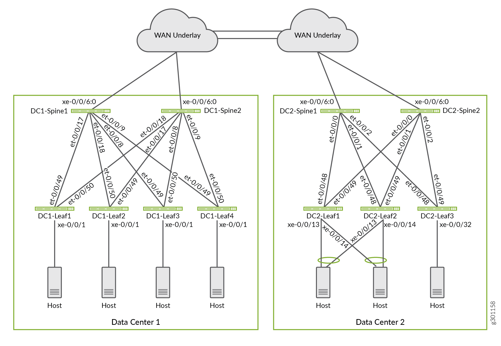
이 배포에서는 ERB(에지 라우팅 브리징) 오버레이 모델로 구성된 두 개의 데이터센터 패브릭 네트워크가 있는 아키텍처를 사용합니다. 데이터센터는 레이어 3 IP 언더레이 네트워크와 상호 연결되어 있습니다. 그림 1 은 두 데이터센터 간의 언더레이 전송을 제공하는 WAN 연결을 보여줍니다. 주니퍼는 완벽한 EVPN-VXLAN DCI 아키텍처를 사용하여 두 데이터센터의 엔드포인트와 가상 머신에 레이어 2 및 레이어 3 연결을 제공합니다.
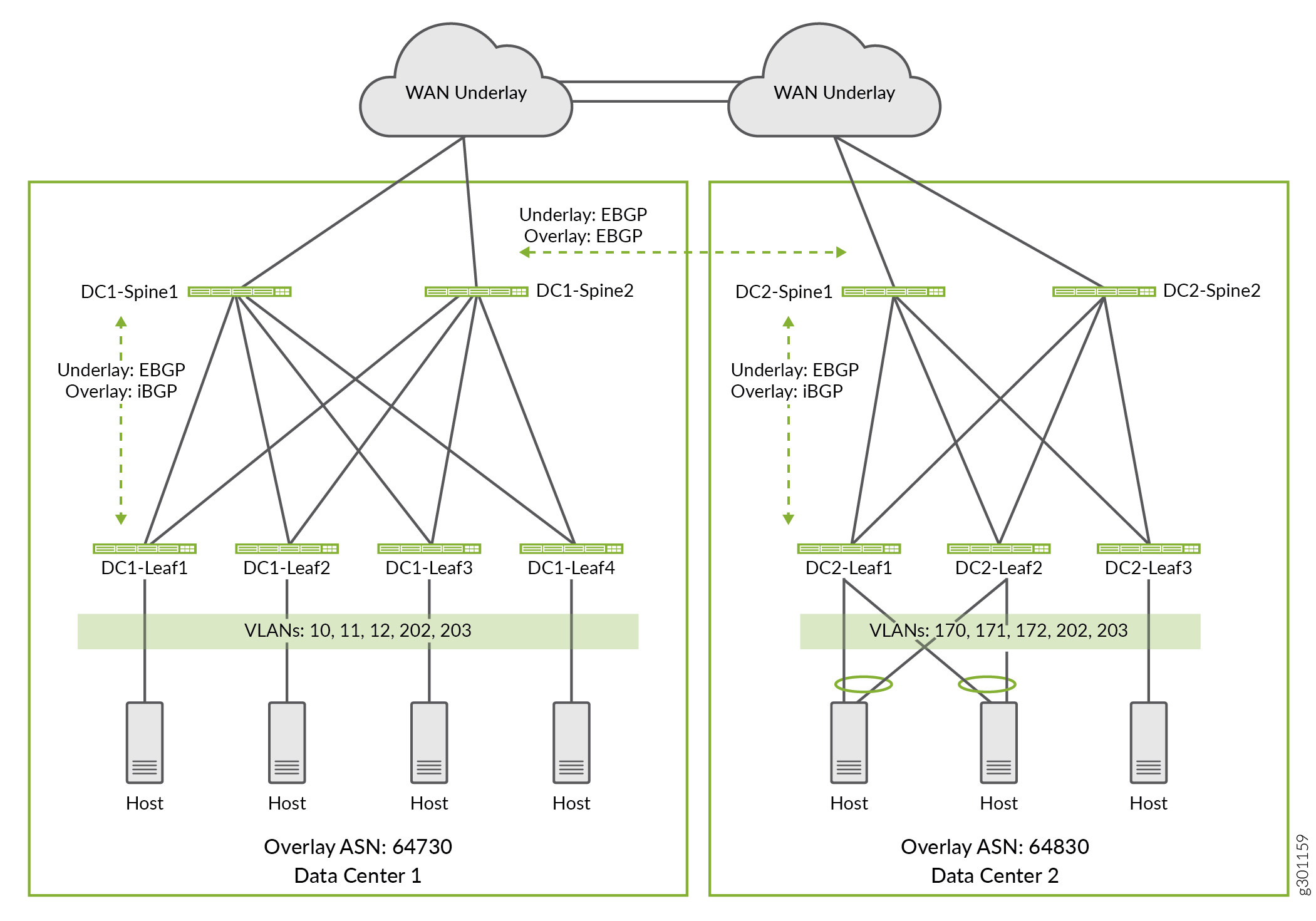
이 예에서 일부 VLAN은 특정 데이터센터 내에만 존재하도록 구성되고 다른 VLAN은 두 데이터센터에 걸쳐 있습니다. 그림 2 는 두 데이터센터에 구성된 VLAN을 보여줍니다. VLAN을 다음과 같이 구성합니다.
VLAN 10, 11, 12는 데이터센터 1에 로컬입니다. 이러한 VLAN의 엔드포인트는 레이어 3 라우팅을 사용하여 데이터센터 2의 다른 VLAN에 도달합니다.
VLAN 170, 171 및 172는 데이터센터 2에 로컬입니다. 이러한 VLAN의 엔드포인트는 레이어 3 라우팅을 사용하여 데이터센터 1의 다른 VLAN에 도달합니다.
VLAN 202 및 203은 데이터센터 1 및 데이터센터 2에 공통입니다. 이러한 VLAN은 두 데이터센터의 모든 리프 디바이스로 확장됩니다. 이러한 VLAN의 엔드포인트는 레이어 2 브리징을 사용하여 다른 데이터센터의 엔드포인트에 도달합니다.
 VLAN
VLAN
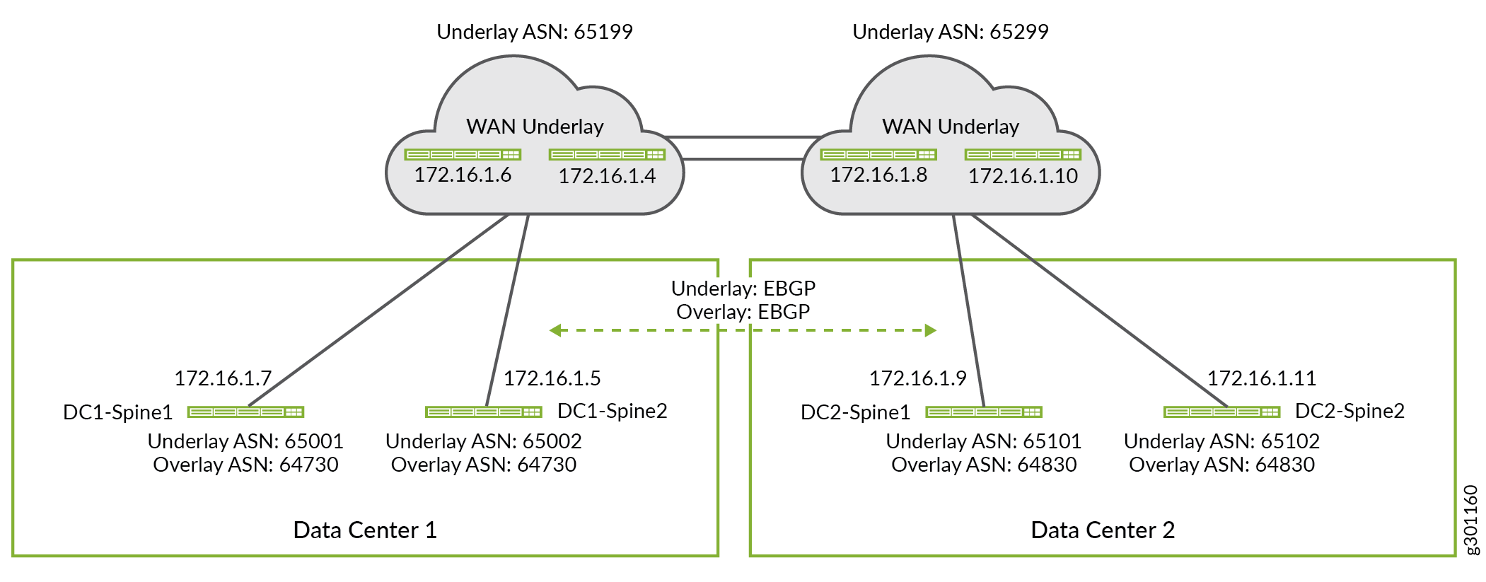
언더레이 네트워크에서 모든 라우팅 프로토콜을 사용할 수 있습니다. 언더레이 라우팅 프로토콜을 사용하면 디바이스가 루프백 IP 주소를 서로 교환할 수 있습니다. 이 예에서 eBGP는 각 데이터센터 패브릭 내에서 언더레이 라우팅 프로토콜로 사용됩니다. eBGP 프로토콜은 두 데이터센터 간의 WAN 연결을 통해 언더레이 네트워크를 확장하는 데에도 사용됩니다. iBGP 또는 eBGP를 DC 간의 오버레이 라우팅 프로토콜로 사용할 수 있습니다. 선택은 데이터센터에 동일한 AS(Autonomous System) 번호를 사용하는지 아니면 다른 AS(Autonomous System) 번호를 사용하는지에 따라 달라집니다. 이 예에서는 패브릭 내의 오버레이 프로토콜에 iBGP를 사용하고 두 데이터센터 간의 eBGP를 사용합니다. 그림 3 에는 이 예에서 사용된 자동 시스템 번호와 IP 주소가 나와 있습니다.
 에 대한 세부 정보
WAN 연결을 위한 경계 스파인 디바이스 구성
요구 사항
경계 스파인 WAN 언더레이 구성
이 페이지에 표시된 구성은 운영 언더레이 및 오버레이 네트워크가 있는 기존 EVPN 패브릭에 설정됩니다. 즉, 이 섹션에서는 DC 언더레이를 WAN 클라우드로 확장하는 데 필요한 추가 구성만 보여줍니다. 대조적으로, 세부 구성은 각 DC 장치의 전체 구성을 보여줍니다.
이 섹션에서는 경계 스파인 디바이스에 대한 WAN 언더레이 구성을 구성하는 방법을 보여줍니다. 간결성을 위해 각 데이터센터에 하나의 스파인 디바이스를 구성하는 단계만 보여드리겠습니다. 유사한 구성 단계를 적용하여 다른 경계 스파인 디바이스를 구성할 수 있습니다.
각 데이터센터의 모든 경계 스파인 디바이스에 대해 이 절차를 반복합니다.
이 예에서 사용되는 전체 구성은 데이터센터의 EVPN-VXLAN 네트워크 세부 구성을 참조하십시오.
경계 스파인 WAN 언더레이
절차
단계별 절차
WAN 피어링 세션을 데이터센터 1 스파인 1(DC1-Spine1)의 기존 언더레이 그룹에 추가합니다. 경계 스파인 디바이스는 WAN 언더레이 네트워크를 사용하여 데이터센터 간에 루프백 주소 정보를 교환합니다. 이를 통해 스파인 디바이스가 wan 클라우드에서 eBGP 오버레이 연결을 형성할 수 있습니다.
set protocols bgp group UNDERLAY neighbor 172.16.1.6 peer-as 65199
이 예에서는 WAN 라우터 피어링이 기존
UNDERLAYBGP 피어 그룹에 추가됩니다. 이 그룹은 이미 DC 언더레이의 일부로 구성되어 있으므로 WAN 라우터를 기존UNDERLAY그룹에 인접 라우터로 추가하기만 하면 됩니다.데이터센터 2 스파인 1(DC2-Spine1)의 기존
UNDERLAY그룹에 WAN 피어링을 추가합니다.set protocols bgp group UNDERLAY neighbor 172.16.1.8 peer-as 65299
두 데이터센터의 스파인 및 리프 디바이스에 사용되는 공통 WAN 언더레이 정책을 구성합니다. 서브넷 10.80.224.128/25는 데이터센터 1의 루프백 주소로, 서브넷 10.0.0.0/24는 데이터센터 2의 루프백 주소로 예약합니다. 정책에서 루프백 주소의 예약된 범위를 지정하면 디바이스가 예약된 루프백 주소로 구성되어 있는 한 디바이스가 추가될 때 정책을 업데이트할 필요가 없습니다.
set policy-options policy-statement UNDERLAY-EXPORT term LOOPBACK from route-filter 10.80.224.128/25 orlonger
set policy-options policy-statement UNDERLAY-EXPORT term LOOPBACK from route-filter 10.0.0.0/24 orlonger
set policy-options policy-statement UNDERLAY-EXPORT term LOOPBACK then accept
set policy-options policy-statement UNDERLAY-EXPORT term DEFAULT then reject
set policy-options policy-statement UNDERLAY-IMPORT term LOOPBACK from route-filter 10.80.224.128/25 orlonger
set policy-options policy-statement UNDERLAY-IMPORT term LOOPBACK from route-filter 10.0.0.0/24 orlonger
set policy-options policy-statement UNDERLAY-IMPORT term LOOPBACK then accept
set policy-options policy-statement UNDERLAY-IMPORT term DEFAULT then reject
이 예에서 언더레이 교환은 DC 내부 및 DC 간의 루프백 경로만 수행합니다. 언더레이에 대한 가져오기 및 내보내기 정책은 두 DC의 모든 디바이스에서 사용할 수 있도록 작성됩니다. 예를 들어
UNDERLAY-EXPORT정책은 로컬 및 원격 DC 루프백 주소와 일치하도록 구성됩니다. DC1의 디바이스에 적용하면 용어만10.80.224.128/25 orlonger일치합니다. DC2에 할당된 루프백 주소에 대한 추가route-filter용어를 사용하면 아무런 문제가 발생하지 않으며 두 DC의 언더레이에 동일한 정책을 적용할 수 있습니다.
경계 스파인 WAN 오버레이
단계별 절차
패브릭 오버레이의 경우, eBGP를 사용하여 두 데이터센터의 모든 경계 스파인 디바이스 간에 eBGP 피어링의 풀 메시를 구성합니다. 스파인 디바이스는 해당 DC 내에서 오버레이 경로 리플렉터로 작동합니다. 오버레이 피어링 세션은 DC 간에 EVPN 오버레이를 확장합니다.
DC 간 오버레이 세션이 WAN 클라우드를 통해 실행되기 때문에 이 피어 그룹에 대해 BFD(Bidirectional Failure Detection)가 활성화되지 않습니다. BFD는 언더레이와 오버레이 모두에서 각 DC 내에서 실행할 수 있습니다.
기본적으로 eBGP는 경로를 재보급할 때 자체 IP 주소를 사용하도록 프로토콜 다음 홉 필드의 IP 주소를 변경합니다. 이 경우 프로토콜 다음 홉 필드가 경로를 생성한 리프 디바이스의 VTEP IP 주소를 사용하려고 합니다. BGP가 오버레이 경로의 다음 홉을 변경하지 못하도록 피어 그룹에서 옵션을 OVERLAY_INTERDC 활성화합니다no-nexthop-change.
DC1-Spine1에서 WAN 오버레이 네트워크를 구성합니다.
set protocols bgp group OVERLAY_INTERDC type external
set protocols bgp group OVERLAY_INTERDC description "Group for overlay EBGP peering to remote DC"
set protocols bgp group OVERLAY_INTERDC multihop no-nexthop-change
set protocols bgp group OVERLAY_INTERDC local-address 10.80.224.149
set protocols bgp group OVERLAY_INTERDC family evpn signaling delay-route-advertisements minimum-delay routing-uptime 480
set protocols bgp group OVERLAY_INTERDC local-as 64730
set protocols bgp group OVERLAY_INTERDC multipath multiple-as
set protocols bgp group OVERLAY_INTERDC neighbor 10.0.0.2 peer-as 64830
set protocols bgp group OVERLAY_INTERDC neighbor 10.0.0.3 peer-as 64830
DC2-Spine1에서 WAN 오버레이 네트워크를 구성합니다.
set protocols bgp group EVPN_FABRIC type internal
set protocols bgp group OVERLAY_INTERDC type external
set protocols bgp group OVERLAY_INTERDC description "Group for overlay EBGP peering to remote DC"
set protocols bgp group OVERLAY_INTERDC multihop no-nexthop-change
set protocols bgp group OVERLAY_INTERDC local-address 10.0.0.2
set protocols bgp group OVERLAY_INTERDC family evpn signaling delay-route-advertisements minimum-delay routing-uptime 480
set protocols bgp group OVERLAY_INTERDC local-as 64830
set protocols bgp group OVERLAY_INTERDC multipath multiple-as
set protocols bgp group OVERLAY_INTERDC neighbor 10.80.224.149 peer-as 64730
set protocols bgp group OVERLAY_INTERDC neighbor 10.80.224.150 peer-as 64730
레이어 2 DCI를 지원하도록 리프 디바이스 구성
두 DC에서 레이어 2(VLAN) 연결을 확장하려면 공유 VLAN의 모든 엔드포인트에 대해 레이어 2 브로드캐스트 도메인을 확장하도록 네트워크를 구성해야 합니다. 이 예에서 VLAN 202 및 203의 엔드포인트는 엔드포인트가 로컬 또는 원격 데이터센터에 있는지 여부에 관계없이 동일한 레이어 2 도메인에 속합니다. 목표는 두 DC 간에 이러한 VLAN을 확장하거나 확장하는 것입니다.
DC 간에 이러한 공유 VLAN에 대한 계층 2 연결을 확장하려면 다음을 구성해야 합니다.
-
계층에서 확장된 VLAN
protocols evpn과 연결된 EVPN 유형 2 및 EVPN 유형 3 경로에 대해 고유한 VXLAN 네트워크 식별자(VNI) 기반 경로 대상을 구성합니다. -
가져오기 정책을 적용하여 계층에서 명령을 사용하여
vrf-import확장된 VLAN에 바인딩된 고유한 경로 대상을 수락합니다switch-options. 확장된 VLAN은 원격 데이터센터에서 보급하는 EVPN 유형 2 및 유형 3 경로입니다.
관련 데이터센터의 모든 리프 디바이스에 대해 이 절차를 반복합니다. 아래 표시된 명령은 두 DC 간에 공유 VLAN을 확장하기 위해 기존 switch-options 및 protocols evpn 계층에 추가됩니다.
절차
단계별 절차
데이터센터 1 리프 1(DC1-Leaf1)에서 확장된 VLAN에 대한 VNI 특정 대상을 구성합니다.
set protocols evpn vni-options vni 1202 vrf-target target:64730:202
set protocols evpn vni-options vni 1203 vrf-target target:64730:203
데이터센터 1 리프 1(DC1-Leaf1)에서 확장된 VLAN의 VNI 대상과 일치하도록 VRF 가져오기 정책을 구성합니다. 또한 이 정책은 자동 검색(AD)에 사용되는 기본 EVPN 유형 1 경로와도 일치합니다. 정책 자체는 이후 단계에서 정의됩니다.
set switch-options vrf-import OVERLAY_IMPORT
데이터센터 2 리프 1(DC2-Leaf1)에서 확장된 VLAN에 대한 VNI 특정 대상을 구성합니다.
set protocols evpn vni-options vni 1202 vrf-target target:64830:202
set protocols evpn vni-options vni 1203 vrf-target target:64830:203
03
데이터센터 2 리프 1(DC2-Leaf1)에서 확장된 VLAN에 대한 VNI 대상과 일치하는 VRF 가져오기 정책을 지정합니다.
set switch-options vrf-import OVERLAY_IMPORT
이전 단계의 계층에서
switch-options vrf-import구성한 VRF 가져오기 정책을 정의합니다. 이 예제에서는 각 데이터센터 및 DC 간에 확장되는 각 계층 2 도메인에 대해 고유한 경로 대상을 사용합니다. 이 정책은 각 DC/POD와 연결된 EVPN 유형 1 AD 경로와 두 데이터센터의 확장된 VLAN에서 사용하는 EVPN 유형 2 및 EVPN 유형 3 경로를 가져오도록 설정됩니다.이 정책은 두 DC의 모든 리프 디바이스에서 구성해야 합니다.
참고:구축 시 데이터센터의 리프 디바이스에 공통 경로 대상을 사용할 수 있습니다. 공통 경로 대상을 사용하는 경우 데이터 센터의 경로는 암시적 가져오기 정책의 일부로 자동으로 가져옵니다.
set policy-options policy-statement OVERLAY_IMPORT term 5 from community comm_pod1
set policy-options policy-statement OVERLAY_IMPORT term 5 then accept
set policy-options policy-statement OVERLAY_IMPORT term 10 from community comm_pod2
set policy-options policy-statement OVERLAY_IMPORT term 10 then accept
set policy-options policy-statement OVERLAY_IMPORT term 20 from community shared_202_fm_pod2
set policy-options policy-statement OVERLAY_IMPORT term 20 from community shared_202_fm_pod1
set policy-options policy-statement OVERLAY_IMPORT term 20 from community shared_203_fm_pod2
set policy-options policy-statement OVERLAY_IMPORT term 20 from community shared_203_fm_pod1
set policy-options policy-statement OVERLAY_IMPORT term 20 then accept
set policy-options community comm_pod1 members target:64730:999
set policy-options community comm_pod2 members target:64830:999
set policy-options community shared_202_fm_pod1 members target:64730:202
set policy-options community shared_202_fm_pod2 members target:64830:202
set policy-options community shared_203_fm_pod1 members target:64730:203
set policy-options community shared_203_fm_pod2 members target:64830:203
및 커뮤니티에 사용되는
comm_pod1값은 각각 DC1 및comm_po2DC2의 리프 디바이스 계층 구조에서 로vrf-target statementswitch-options지정된 값과 일치합니다. 이는 자동 검색에 사용되는 모든 EVPN 유형 1 경로에 추가되는 경로 대상입니다. 이 대상은 계층에 지정된 VNI 특정 대상이 없는 다른 모든 EVPN 경로에도protocols evpn연결됩니다.이 예에서 확장된 VLAN은 VNI 특정 대상을 사용하도록 구성됩니다. 따라서 가져오기 정책은 각 DC에서 사용하는 세 대상 모두에서 일치하도록 작성됩니다. 다시 한 번, 이 접근 방식을 사용하면 두 DC의 모든 리프 디바이스에서 공통 정책을 사용할 수 있습니다.
요구 사항
레이어 3 DCI를 지원하도록 리프 디바이스 구성
EVPN 유형 5 경로는 확장되지 않은 VLAN에 대한 DC 간의 레이어 3 연결에 사용됩니다. EVPN 유형 5 경로는 IP 접두사 경로라고도 합니다. 즉, Type 5 경로는 레이어 2 브로드캐스트 도메인이 데이터센터 내에 제한될 때 사용됩니다. EVPN 유형 5 경로는 확장되지 않은 VLAN과 연결된 IRB 인터페이스의 IP 접두사를 광고하여 레이어 3 연결을 활성화합니다. 이 예에서 VLAN(10, 11, 12)은 데이터센터 1로 제한되고 VLAN(170, 171, 172)은 데이터센터 2 내에 제한됩니다. IP 접두사 경로를 사용하여 이러한 VLAN의 구성원 간에 레이어 3 데이터센터 간 연결을 설정합니다.
절차
단계별 절차
EVPN 유형 5 경로를 지원하는 레이어 3 VRF를 정의하여 DC1-Leaf1에서 레이어 3 DCI를 구성합니다.
set routing-instances TENANT_1_VRF description "VRF for Tenant_1"
set routing-instances TENANT_1_VRF instance-type vrf
set routing-instances TENANT_1_VRF interface irb.10
set routing-instances TENANT_1_VRF interface irb.11
set routing-instances TENANT_1_VRF interface irb.12
set routing-instances TENANT_1_VRF interface irb.202
set routing-instances TENANT_1_VRF interface irb.203
set routing-instances TENANT_1_VRF interface lo0.1
set routing-instances TENANT_1_VRF route-distinguisher 10.80.225.140:9999
set routing-instances TENANT_1_VRF vrf-import VRF1_VRF1_T5_RT_IMPORT
set routing-instances TENANT_1_VRF vrf-export VRF1_VRF1_T5_RT_EXPORT
set routing-instances TENANT_1_VRF vrf-target target:1:65001
set routing-instances TENANT_1_VRF vrf-table-label
set routing-instances TENANT_1_VRF routing-options multipath
set routing-instances TENANT_1_VRF protocols evpn ip-prefix-routes advertise direct-nexthop
set routing-instances TENANT_1_VRF protocols evpn ip-prefix-routes encapsulation vxlan
set routing-instances TENANT_1_VRF protocols evpn ip-prefix-routes vni 9999
set routing-instances TENANT_1_VRF protocols evpn ip-prefix-routes export T5_EXPORT
EVPN 유형 5 경로를 지원하는 레이어 3 VRF를 정의하여 DC2-Leaf1에서 레이어 3 DCI를 구성합니다.
set routing-instances TENANT_1_VRF description "VRF for Tenant_1"
set routing-instances TENANT_1_VRF instance-type vrf
set routing-instances TENANT_1_VRF interface irb.170
set routing-instances TENANT_1_VRF interface irb.171
set routing-instances TENANT_1_VRF interface irb.172
set routing-instances TENANT_1_VRF interface irb.202
set routing-instances TENANT_1_VRF interface irb.203
set routing-instances TENANT_1_VRF interface lo0.1
set routing-instances TENANT_1_VRF route-distinguisher 10.0.1.19:9999
set routing-instances TENANT_1_VRF vrf-import VRF1_T5_RT_IMPORT
set routing-instances TENANT_1_VRF vrf-export VRF1_T5_RT_EXPORT
set routing-instances TENANT_1_VRF vrf-target target:1:65001
set routing-instances TENANT_1_VRF vrf-table-label
set routing-instances TENANT_1_VRF routing-options multipath
set routing-instances TENANT_1_VRF protocols evpn ip-prefix-routes advertise direct-nexthop
set routing-instances TENANT_1_VRF protocols evpn ip-prefix-routes encapsulation vxlan
set routing-instances TENANT_1_VRF protocols evpn ip-prefix-routes vni 9999
set routing-instances TENANT_1_VRF protocols evpn ip-prefix-routes export T5_EXPORT
DC1의 모든 리프 디바이스에 대한 레이어 3 DCI 정책 구성
set policy-options policy-statement T5_EXPORT term fm_direct from protocol direct
set policy-options policy-statement T5_EXPORT term fm_direct then accept
set policy-options policy-statement T5_EXPORT term fm_static from protocol static
set policy-options policy-statement T5_EXPORT term fm_static then accept
set policy-options policy-statement T5_EXPORT term fm_v4_host from protocol evpn
set policy-options policy-statement T5_EXPORT term fm_v4_host from route-filter 0.0.0.0/0 prefix-length-range /32-/32
set policy-options policy-statement T5_EXPORT term fm_v4_host then accept
set policy-options policy-statement T5_EXPORT term fm_v6_host from protocol evpn
set policy-options policy-statement T5_EXPORT term fm_v6_host from route-filter 0::0/0 prefix-length-range /128-/128
set policy-options policy-statement T5_EXPORT term fm_v6_host then accept

set policy-options policy-statement VRF1_T5_RT_EXPORT term t1 then community add target_t5_pod1
set policy-options policy-statement VRF1_T5_RT_EXPORT term t1 then accept

set policy-options policy-statement VRF1_T5_RT_IMPORT term t1 from community target_t5_pod1
set policy-options policy-statement VRF1_T5_RT_IMPORT term t1 then accept
set policy-options policy-statement VRF1_T5_RT_IMPORT term t2 from community target_t5_pod2
set policy-options policy-statement VRF1_T5_RT_IMPORT term t2 then accept

set policy-options community target_t5_pod1 members target:64730:9999
set policy-options community target_t5_pod2 members target:64830:9999
DC2의 모든 리프 디바이스에 대한 레이어 3 DCI 정책 구성
set policy-options policy-statement T5_EXPORT term fm_direct from protocol direct
set policy-options policy-statement T5_EXPORT term fm_direct then accept
set policy-options policy-statement T5_EXPORT term fm_static from protocol static
set policy-options policy-statement T5_EXPORT term fm_static then accept
set policy-options policy-statement T5_EXPORT term fm_v4_host from protocol evpn
set policy-options policy-statement T5_EXPORT term fm_v4_host from route-filter 0.0.0.0/0 prefix-length-range /32-/32
set policy-options policy-statement T5_EXPORT term fm_v4_host then accept
set policy-options policy-statement T5_EXPORT term fm_v6_host from protocol evpn
set policy-options policy-statement T5_EXPORT term fm_v6_host from route-filter 0::0/0 prefix-length-range /128-/128
set policy-options policy-statement T5_EXPORT term fm_v6_host then accept

set policy-options policy-statement VRF1_T5_RT_EXPORT term t1 then community add target_t5_pod2
set policy-options policy-statement VRF1_T5_RT_EXPORT term t1 then accept

set policy-options policy-statement VRF1_T5_RT_IMPORT term t1 from community target_t5_pod1
set policy-options policy-statement VRF1_T5_RT_IMPORT term t1 then accept
set policy-options policy-statement VRF1_T5_RT_IMPORT term t2 from community target_t5_pod2
set policy-options policy-statement VRF1_T5_RT_IMPORT term t2 then accept

set policy-options community target_t5_pod1 members target:64730:9999
set policy-options community target_t5_pod2 members target:64830:9999
경로 대상 가져오기를 위한 대체 정책 구성
요구 사항
이 예에서 자동 파생된 경로 대상에는 식별자의 일부로 오버레이 AS 번호가 포함됩니다. 결과적으로 데이터센터 1과 데이터센터 2에서 동일한 VNI에 대해 서로 다른 경로 대상이 생깁니다.
보다 간단한 정책 구성의 경우, 계층에서 옵션과 vrf-target 함께 auto 문을 포함하여 경로 대상을 자동으로 도출할 수 있습니다 switch-options . 을 활성화 vrf-target auto하면 Junos가 EVPN 유형 2 및 유형 3 경로에 사용되는 경로 대상을 자동으로 생성합니다. EVPN-VXLAN의 경우, 경로 대상은 VXLAN 네트워크 식별자(VNI)에서 자동으로 파생됩니다. 이 예에서 VNI 1202에 대한 자동 파생 EVPN 유형 2 및 유형 3 경로 대상은 데이터 센터 1의 target:64730:268436658 및 데이터 센터 2의 target:64830:268436658입니다. 그런 다음 이러한 경로 대상은 연결된 EVPN 유형 2 및 유형 3 경로에 연결됩니다. 명령문은 vrf-target auto 이러한 VNI에 대해 동일한 경로 대상 값을 일치시키고 가져오기 위한 암시적 가져오기 정책을 생성합니다.
더 간단한 정책을 사용하면 VLAN 202 및 203에 대한 EVPN 유형 2 및 3 경로를 자동으로 가져오지 않습니다. 다른 AS(Autonomous System) 번호를 가진 데이터센터에서 EVPN 유형 2 및 3 경로를 가져오려면 문을 포함합니다 vrf-target auto import-as .
다음은 데이터센터 1의 리프 1에 대한 구성 예입니다.
set switch-options vrf-import OVERLAY_IMPORT
set switch-options vrf-target target:64730:999
set switch-options vrf-target auto import-as 64830 vni-list 1202
set switch-options vrf-target auto import-as 64830 vni-list 1203
set protocols evpn extended-vni-list 110
set protocols evpn extended-vni-list 111
set protocols evpn extended-vni-list 112
set protocols evpn extended-vni-list 1202
set protocols evpn extended-vni-list 1203
set policy-options policy-statement OVERLAY_IMPORT term 5 from community comm_pod1
set policy-options policy-statement OVERLAY_IMPORT term 5 then accept
set policy-options policy-statement OVERLAY_IMPORT term 10 from community comm_pod2
set policy-options policy-statement OVERLAY_IMPORT term 10 then accept
set policy-options community comm_pod1 members target:64730:999
set policy-options community comm_pod2 members target:64830:999
확인
절차
요구 사항
개요
BGP 피어링 확인
목적
언더레이, 오버레이 및 DC 간 BGP 피어링 세션을 확인합니다.
작업
모든 언더레이 및 오버레이 BGP 피어링 세션이 설정되었는지 확인합니다. 여기에는 WAN 클라우드를 통해 형성된 DC 간의 eBGP 오버레이 피어링이 포함됩니다.
다음은 DC2의 DC2-Spine1 디바이스에서 가져온 것입니다. 모든 BGP 피어링 세션은 두 DC의 모든 리프 및 스파인 디바이스에서 설정되어야 합니다.
user@dc2spine1> show bgp summary

Threading mode: BGP I/O
Groups: 3 Peers: 9 Down peers: 0
Table          Tot Paths  Act Paths Suppressed    History Damp State    Pending
inet.0
                      10          5          0          0          0          0
bgp.evpn.0
                      99         99          0          0          0          0
Peer                     AS      InPkt     OutPkt    OutQ   Flaps Last Up/Dwn State|#Active/Received/Accepted/Damped...
10.0.0.14             64830      11634      11582       0       1     8:49:40 Establ
  bgp.evpn.0: 36/36/36/0
10.0.0.18             64830      11646      11604       0       2     8:49:40 Establ
  bgp.evpn.0: 36/36/36/0
10.0.0.19             64830      11652      11603       0       3     8:49:38 Establ
  bgp.evpn.0: 36/36/36/0
10.80.224.149         64730      11621      11622       0       6     8:49:31 Establ
  bgp.evpn.0: 27/27/27/0
10.80.224.150         64730      11630      11600       0       6     8:49:31 Establ
  bgp.evpn.0: 27/27/27/0
172.16.0.1            65019      11640      11582       0       2     8:49:39 Establ
  inet.0: 1/1/1/0
172.16.0.3            65018      11634      11583       0       1     8:49:42 Establ
  inet.0: 1/1/1/0
172.16.1.5            65229      11678      11500       0       1     8:49:43 Establ
  inet.0: 3/8/3/0
172.16.1.8            65229      11688      11581       0       1     8:49:43 Establ
  inet.0: 3/8/3/0
의미
DC2-Spine1의 출력은 모든 BGP 세션이 설정되었음을 확인합니다. 로컬 리프당 하나의 언더레이 및 오버레이 세션과 WAN 피어링 세션 및 원격 DC의 스파인 디바이스에 대한 2개의 오버레이 피어링 세션이 있습니다. 이렇게 하면 총 세션 수가 9개가 됩니다. 원격 DC에 대한 오버레이 피어링을 설정하는 기능은 WAN 클라우드를 통한 적절한 언더레이 경로 교환을 확인합니다.
리프 디바이스에서 VTEP 확인
목적
서로 다른 데이터센터에 있는 두 리프 디바이스 간의 레이어 2 연결을 확인합니다.
작업
VTEP 인터페이스가 로컬 및 원격 데이터센터의 리프 디바이스에서 작동하는지 확인합니다.
다음은 데이터센터 1의 리프에서 VTEP 상태 출력의 코드 조각입니다.
user@dc1leaf1> show interfaces vtep

Physical interface: vtep, Enabled, Physical link is Up
  Interface index: 641, SNMP ifIndex: 508
  Type: Software-Pseudo, Link-level type: VxLAN-Tunnel-Endpoint, MTU: Unlimited, Speed: Unlimited
  Device flags   : Present Running
  Link type      : Full-Duplex
  Link flags     : None
  Last flapped   : Never
    Input packets : 0
    Output packets: 0
.
.
.
  Logical interface vtep.32769 (Index 555) (SNMP ifIndex 539)
    Flags: Up SNMP-Traps Encapsulation: ENET2
    VXLAN Endpoint Type: Remote, VXLAN Endpoint Address: 10.80.224.141, L2 Routing Instance: default-switch, L3 Routing Instance: default
    Input packets : 731317
    Output packets: 469531709
    Protocol eth-switch, MTU: Unlimited
      Flags: Trunk-Mode
.
.
.
  Logical interface vtep.32770 (Index 572) (SNMP ifIndex 541)
    Flags: Up SNMP-Traps Encapsulation: ENET2
    VXLAN Endpoint Type: Remote, VXLAN Endpoint Address: 10.0.0.18, L2 Routing Instance: default-switch, L3 Routing Instance: default
    Input packets : 136973831
    Output packets: 141901343
    Protocol eth-switch, MTU: Unlimited
      Flags: Trunk-Mode
.
.
.
의미
DC1-Leaf1의 출력은 이 리프 디바이스와 로컬 데이터센터 패브릭의 다른 리프 디바이스 사이에 레이어 2 VXLAN 터널이 생성됨을 보여줍니다(DC1의 리프 2에 대한 VTEP 주소는 코드 조각에 표시됨). 또한 출력은 이 리프 디바이스와 원격 데이터센터 패브릭의 다른 리프 디바이스 간에 VTEP가 학습되었음을 보여줍니다(DC2의 리프 2에 대한 VTEP는 코드 조각에 표시됨). 입력 및 출력 패킷 카운터는 이러한 VTEP의 엔드포인트 간에 성공적인 데이터 전송을 확인합니다.
EVPN 유형 1 경로 확인
목적
EVPN 유형 1 경로가 라우팅 테이블에 추가되고 있는지 확인합니다.
작업
EVPN type1(AD/ESI) 경로가 수신 및 설치되었는지 확인합니다.
user@dc1leaf1>show route | match 1:10.0.0.181:10.0.0.18:0::0202020201::FFFF:FFFF/192 AD/ESI 1:10.0.0.18:0::0202020202::FFFF:FFFF/192 AD/ESI user@dc1leaf1>show route extensive | find 1:10.0.0.18:0::0202020201:1:10.0.0.18:0::0202020201::FFFF:FFFF/192 AD/ESI (1 entry, 0 announced) *BGP Preference: 170/-101 Route Distinguisher: 10.0.0.18:0 Next hop type: Indirect, Next hop index: 0 Address: 0xbd78c94 Next-hop reference count: 50 Source: 10.80.224.149 Protocol next hop: 10.0.0.18 Indirect next hop: 0x2 no-forward INH Session ID: 0x0 State: <Active Int Ext> Local AS: 64730 Peer AS: 64730 Age: 1:22 Metric2: 0 Validation State: unverified Task: BGP_64730.10.80.224.149 AS path: 64830 I Communities: target:64830:999 encapsulation:vxlan(0x8) esi-label:0x0:all-active (label 0) Import Accepted Route Label: 1 Localpref: 100 Router ID: 10.80.224.149 Secondary Tables: default-switch.evpn.0 Indirect next hops: 1 Protocol next hop: 10.0.0.18 Indirect next hop: 0x2 no-forward INH Session ID: 0x0 Indirect path forwarding next hops: 1 Next hop type: Router Next hop: 10.80.224.2 via et-0/0/49.0 Session Id: 0x0 10.0.0.18/32 Originating RIB: inet.0 Node path count: 1 Forwarding nexthops: 1 Nexthop: 10.80.224.2 via et-0/0/49.0 Session Id: 0
EVPN 라우팅 인스턴스 정보를 표시합니다. 아래 코드 조각은 DC1의 리프 1에서 가져온 것입니다.
user@dc1leaf1> show evpn instance extensive

Instance: __default_evpn__
  Route Distinguisher: 10.80.224.140:0
  Number of bridge domains: 0
  Number of neighbors: 0

. . .
    ESI: 00:00:00:00:00:02:02:02:02:01
      Status: Resolved
      Number of remote PEs connected: 2
        Remote PE        MAC label  Aliasing label  Mode
        10.0.0.19        1203       0               all-active
        10.0.0.18        0          0               all-active
    ESI: 00:00:00:00:00:02:02:02:02:02
      Status: Resolved
      Number of remote PEs connected: 2
        Remote PE        MAC label  Aliasing label  Mode
        10.0.0.19        0          0               all-active
        10.0.0.18        0          0               all-active

. . .
의미
이러한 출력은 DC1-Leaf1이 원격 데이터센터에서 EVPN type1(AD/ESI) 경로를 수신했음을 보여줍니다. 명령의 출력을 사용하여 이러한 경로의 show route extensive 경로 대상이 "target:64830:999"이고 이러한 경로가 성공적으로 설치되었음을 표시할 수 있습니다. ESI 02:02:02:02:01 및 02:02:02:02:02는 원격 데이터센터의 이더넷 세그먼트입니다. 또한 이 출력은 IP 주소가 10.0.0.18 및 10.0.0.19인 원격 PE가 이러한 이더넷 세그먼트의 일부임을 보여줍니다.
EVPN 유형 2 경로 확인
목적
EVPN 유형 2 경로가 라우팅 테이블에 추가되고 있는지 확인합니다.
작업
EVPN 유형 2 경로가 수신되어 데이터센터 1의 리프 디바이스에 있는 경로 테이블에 설치되었는지 확인합니다.
show route를 사용하여 원격 데이터센터에 있는 VLAN 203에서 엔드포인트를 찾습니다.
user@dc1leaf1>show route | match 00:10:94:00:00:06

2:10.0.0.18:1::1203::00:10:94:00:00:06/304 MAC/IP
2:10.0.0.18:1::1203::00:10:94:00:00:06::10.1.203.151/304 MAC/IP
자세한 내용을 보려면 show route(경로 표시)에 대한 세부 정보 보기를 사용합니다.
user@dc1leaf1> show route extensive | find 2:10.0.0.18:1::1203::00:10:94:00:00:06::10.1.203.151/304

2:10.0.0.18:1::1203::00:10:94:00:00:06::10.1.203.151/304 MAC/IP (1 entry, 0 announced)
        *BGP    Preference: 170/-101
                Route Distinguisher: 10.0.0.18:1
                Next hop type: Indirect, Next hop index: 0
                Address: 0xbd78c94
                Next-hop reference count: 58
                Source: 10.80.224.149
                Protocol next hop: 10.0.0.18
                Indirect next hop: 0x2 no-forward INH Session ID: 0x0
                State: <Active Int Ext>
                Local AS: 64730 Peer AS: 64730
                Age: 1:31       Metric2: 0
                Validation State: unverified
                Task: BGP_64730.10.80.224.149
                AS path: 64830 I
                Communities: target:64830:203 encapsulation:vxlan(0x8)
                Import Accepted
                Route Label: 1203
                ESI: 00:00:00:00:00:00:00:00:01:01
                Localpref: 100
                Router ID: 10.80.224.149
                Secondary Tables: default-switch.evpn.0
                Indirect next hops: 1
                        Protocol next hop: 10.0.0.18
                        Indirect next hop: 0x2 no-forward INH Session ID: 0x0
                        Indirect path forwarding next hops: 1
                                Next hop type: Router
                                Next hop: 10.80.224.2 via et-0/0/49.0
                                Session Id: 0x0
                                10.0.0.18/32 Originating RIB: inet.0
                                  Node path count: 1
                                  Forwarding nexthops: 1
                                        Nexthop: 10.80.224.2 via et-0/0/49.0
                                        Session Id: 0
show vlans 명령을 사용하여 VLAN 203에 대한 정보를 찾습니다.
user@dc1leaf1> show vlans v203

Routing instance        VLAN name             Tag          Interfaces
default-switch          v203                  203
                                                           esi.1860*
                                                           vtep.32769*
                                                           vtep.32770*
                                                           vtep.32772*
																				   xe-0/0/1.0*
위의 출력은 VLAN 203이 VTEP "vtep.32769 - 10.80.224.141 - DC1-Leaf2", "vtep.32772 - 10.0.0.18 - DC2-Leaf2", "vtep.32770 - 10.0.0.19 - DC2-Leaf1"에 구성되어 있음을 보여줍니다. 또한 출력은 이러한 VTEP에서 VLAN v203에 연결된 엔드포인트가 있음을 나타냅니다. 을( show interfaces VTEP 를) 사용하여 이러한 VTEP에 대한 VTEP IP 주소를 가져올 수 있습니다. show evpn database 및 명령을 show ethernet-switching-table 사용하여 이러한 엔드포인트의 MAC 주소 및 IP 주소를 찾습니다.
show evpn database 을(를) 사용하여 EVPN 데이터베이스에서 항목을 찾습니다.
user@dc1leaf1> show evpn database neighbor 10.0.0.18

Instance: default-switch
VLAN  DomainId  MAC address        Active source                  Timestamp        IP address
     1202       3c:8c:93:2e:a8:c0  10.0.0.18                      Jul 18 23:41:54  10.1.202.18
     1203       00:10:94:00:00:06  00:00:00:00:00:02:02:02:02:01  Jul 19 03:16:42  10.1.203.151
     1203       3c:8c:93:2e:a8:c0  10.0.0.18                      Jul 18 23:41:54  10.1.203.18
show ethernet-switching table 명령을 사용하여 특정 MAC 주소에 대한 정보를 표시합니다.
user@dc1leaf1> show ethernet-switching table 00:10:94:00:00:06


MAC flags (S - static MAC, D - dynamic MAC, L - locally learned, P - Persistent static
           SE - statistics enabled, NM - non configured MAC, R - remote PE MAC, O - ovsdb MAC)


Ethernet switching table : 29 entries, 29 learned
Routing instance : default-switch
   Vlan                MAC                 MAC      Logical                Active
   name                address             flags    interface              source
   v203                00:10:94:00:00:06   DR       esi.1874               00:00:00:00:00:02:02:02:02:01
의미
출력은 원격 PE의 VLAN 203에 있는 디바이스의 MAC 주소가 EVPN 데이터베이스에 설치되었으며 이더넷 스위칭 테이블에 있음을 보여줍니다.
레이어 3 DCI 확인
목적
레이어 3 경로가 라우팅 테이블에 설치되었는지 확인합니다.
작업
EVPN 유형 5 경로가 수신되어 데이터센터 1의 리프 디바이스에 있는 경로 테이블에 설치되었는지 확인합니다.
VLAN 170의 서브넷인 10.1.170.0/24에서 EVPN 유형 5 경로를 수신하고 있는지 확인합니다. 이 VLAN은 데이터센터 2에 로컬입니다. 데이터센터 1에서 이 서브넷에 도달하려면 레이어 3 라우팅이 필요합니다.
user@dc1leaf1> show route | match 5: | match 10.1.170.0

5:10.0.1.18:9999::0::10.1.170.0::24/248
5:10.0.1.19:9999::0::10.1.170.0::24/248

. . .
10.1.170.0/24 네트워크의 EVPN 유형 5 경로에 대한 자세한 내용을 확인할 수 있습니다. 이 서브넷을 위해 이 리프 디바이스에서 전송된 트래픽은 VNI 9999의 VXLAN 터널에서 캡슐화되어 데이터센터 2의 원격 리프 10.0.0.18로 전송됩니다.
user@dc1leaf1> show route 10.1.170.0/24 extensive

TENANT_1_VRF.inet.0: 28 destinations, 57 routes (28 active, 0 holddown, 0 hidden)
10.1.170.0/24 (3 entries, 1 announced)
TSI:
KRT in-kernel 10.1.170.0/24 -> {composite(1742)}
        *EVPN   Preference: 170/-101
                Next hop type: Indirect, Next hop index: 0
                Address: 0xdfacd74
                Next-hop reference count: 9
                Next hop type: Router, Next hop index: 1738
                Next hop: 10.80.224.2 via et-0/0/49.0, selected
                Session Id: 0x0
                Protocol next hop: 10.0.0.18
                Composite next hops: 1
                        Protocol next hop: 10.0.0.18
                        Composite next hop: 0xb959d60 1740 INH Session ID: 0x0
                          VXLAN tunnel rewrite:
                            MTU: 0, Flags: 0x0
                            Encap table ID: 0, Decap table ID: 11
                            Encap VNI: 9999, Decap VNI: 9999
                            Source VTEP: 10.80.224.140, Destination VTEP: 10.0.0.18
                            SMAC: e4:5d:37:ea:98:00, DMAC: 3c:8c:93:2e:a8:c0
                        Indirect next hop: 0xc710304 131071 INH Session ID: 0x0
                        Indirect path forwarding next hops: 1
                                Next hop type: Router
                                Next hop: 10.80.224.2 via et-0/0/49.0
                                Session Id: 0x0
                                10.0.0.18/32 Originating RIB: inet.0
                                  Node path count: 1
                                  Forwarding nexthops: 1
                                        Nexthop: 10.80.224.2 via et-0/0/49.0
                                        Session Id: 0
출력은 10.1.170.0/24 서브넷에 대한 경로가 이 리프 디바이스에 존재함을 확인합니다. 호스트 경로를 내보내고 가져오기 때문에 특정 EVPN 유형 5 호스트 경로를 볼 수 있습니다.
user@dc1leaf1> show route table TENANT_1_VRF.inet.0 10.1.170.0/24

TENANT_1_VRF.inet.0: 21 destinations, 35 routes (21 active, 0 holddown, 0 hidden)
@ = Routing Use Only, # = Forwarding Use Only
+ = Active Route, - = Last Active, * = Both

10.1.170.0/24      @[EVPN/170] 1d 06:38:11
                    >  to 10.80.224.2 via et-0/0/49.0
                    >  to 10.80.224.12 via et-0/0/50.0
                    [EVPN/170] 1d 06:38:09
                    >  to 10.80.224.2 via et-0/0/49.0
                    >  to 10.80.224.12 via et-0/0/50.0
                   #[Multipath/255] 1d 06:38:09, metric2 0
                    >  to 10.80.224.2 via et-0/0/49.0
                    >  to 10.80.224.12 via et-0/0/50.0
10.1.170.100/32    @[EVPN/170] 00:00:23
                    >  to 10.80.224.2 via et-0/0/49.0
                    >  to 10.80.224.12 via et-0/0/50.0
                    [EVPN/170] 00:00:22
                    >  to 10.80.224.2 via et-0/0/49.0
                    >  to 10.80.224.12 via et-0/0/50.0
                   #[Multipath/255] 00:00:22, metric2 0
                    >  to 10.80.224.2 via et-0/0/49.0
                    >  to 10.80.224.12 via et-0/0/50.0
출력은 이 리프 디바이스의 10.1.203.0/24 서브넷에 대한 경로를 보여줍니다. 이 경우 VLAN 203은 두 데이터센터에 걸쳐 확장됩니다. EVPN 유형 5 경로만 서브넷 경로로 제한하면 L2 확장 VLAN에 대한 비대칭 VNI 라우팅이 생깁니다. L2 확장 VLAN에 대한 VNI 간 라우팅을 위한 대칭 모델을 구축하려는 경우 EVPN 유형 5 호스트 경로를 내보내고 가져와야 합니다.
이 예에서는 에 적용된 TENANT_1_VRF 정책을 EVPN 프로토콜의 내보내기 정책으로 사용하여 T5_EXPORT /32 호스트 경로의 보급에 영향을 미칩니다. 따라서 이 예제에서는 해당 VLAN이 DC 간에 확장될 때 VLAN 간 라우팅에 대한 대칭 라우팅을 보여 줍니다.
user@dc1leaf1>show route table TENANT_1_VRF.inet.0 10.1.203.0/24

TENANT_1_VRF.inet.0: 28 destinations, 57 routes (28 active, 0 holddown, 0 hidden)
+ = Active Route, - = Last Active, * = Both

10.1.203.0/24      *[Direct/0] 1d 05:42:50
                    >  via irb.203
                    [EVPN/170] 1d 05:42:50
                    >  to 10.80.224.2 via et-0/0/49.0
                       to 10.80.224.12 via et-0/0/50.0
                    [EVPN/170] 1d 05:42:50
                    >  to 10.80.224.2 via et-0/0/49.0
                       to 10.80.224.12 via et-0/0/50.0
                    [EVPN/170] 1d 05:42:50
                    >  to 10.80.224.2 via et-0/0/49.0
                       to 10.80.224.12 via et-0/0/50.0
                    [EVPN/170] 1d 05:42:50
                    >  to 10.80.224.2 via et-0/0/49.0
                       to 10.80.224.12 via et-0/0/50.0
                    [EVPN/170] 01:06:19
                    >  to 10.80.224.2 via et-0/0/49.0
                       to 10.80.224.12 via et-0/0/50.0
                    [EVPN/170] 01:17:41
                    >  to 10.80.224.2 via et-0/0/49.0
                       to 10.80.224.12 via et-0/0/50.0
10.1.203.1/32      *[Local/0] 1d 05:42:50
                       Local via irb.203
10.1.203.11/32     *[Local/0] 1d 05:42:50
                       Local via irb.203
10.1.203.52/32     *[EVPN/7] 02:52:51
                    >  via irb.203
의미
이 출력은 10.1.203.0/24 서브넷과 10.1.203.52/32(데이터센터 2에 있는 엔드포인트의 IP 주소)에 대한 특정 호스트 경로가 모두 설치되었음을 보여줍니다. 10.1.203.52/32 경로의 경우 EVPN 유형 2 경로보다 EVPN 유형 5 경로가 더 선호됩니다. 그 결과 레이어 2 스트레치 VLAN을 통한 대칭 VNI 간 라우팅이 발생합니다.