예: VPLS 구성(BGP 신호 전송)
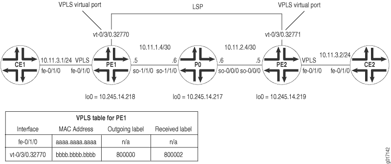
그림 1에서는 라우터 PE1과 PE2 간에 간단한 VPLS 토폴로지가 활성화되어 있습니다. CE 라우터 CE1 및 CE2는 이더넷 기반 인터페이스를 사용하여 VLAN 600을 로컬 PE 라우터에 연결합니다. PE 라우터 PE1 및 PE2는 MPLS, BGP, RSVP 및 OSPF를 실행하는 서비스 프로바이더 백본에서 활성화된 LSP에 의해 서로 연결됩니다.
라는 greenVPLS 라우팅 인스턴스에서 PE1은 로컬 인터페이스fe-0/1/0 와 의 가상 포트 vt-0/3/0.32770 를 가지고 있습니다(가상 포트는 VPLS가 구성되면 터널 서비스 PIC에서 동적으로 생성됨). PE2에는 동일한 green 인스턴스의 로컬 인터페이스 fe-0/1/0 와 가상 포트 vt-0/3/0.32771 가 있습니다. 그 결과, 라우터 CE1과 CE2는 이더넷 트래픽을 LAN에서 물리적으로 연결된 것처럼 서로 전송합니다.
라우터 CE1에서 구성해야 하는 유일한 항목은 PE1에 연결하는 고속 이더넷 인터페이스입니다. CE2에서 나중에 일치시킬 수 있도록 VLAN 식별자와 IP 주소를 적어보십시오.
라우터 CE1
[edit]
interfaces {
    fe-0/1/0 {
        vlan-tagging; # Configure VLAN tagging for VLAN VPLS or extended VLAN VPLS.
        unit 0 {
            vlan-id 600; # The Ethernet interface on CE2 must use the same VLAN ID.
            family inet {
                address 10.11.3.1/24; # The interface on CE2 must use the same prefix.
            }
        }
    }
}
라우터 PE1이 MX 시리즈 디바이스인 경우 터널 서비스 인터페이스를 구성해야 합니다.
MX 시리즈 라우터에서 터널 인터페이스를 생성하려면 [edit chassis fpc slot-number pic number] 계층 수준에서 문을 포함합니다tunnel-services. 터널 인터페이스의 대역폭을 구성하려면 [edit chassis fpc slot-number pic number tunnel services] 계층 수준에서 문을 포함합니다bandwidth.
다음 예는 MX 시리즈 라우터의 슬롯 0에 설치된 DPC의 PFE 3에 구성된 1Gbps 대역폭을 가진 터널 인터페이스를 보여줍니다.
[edit chassis]
fpc 0 {
    pic 3 {
        tunnel services {
            bandwidth 1g;
        }
    }
}
라우터 PE1에서 BGP, MPLS, OSPF 및 RSVP를 구성하여 VPLS에 라우터를 준비합니다. (이러한 프로토콜은 VPLS를 포함한 대부분의 레이어 2 VPN 관련 애플리케이션의 기초입니다.) VPLS는 signaling 레이어 2 VPN과 마찬가지로 내부 BGP에 동일한 인프라를 사용하기 때문에 계층 수준에서 문을 [edit protocols bgp group group-name family l2vpn] 포함합니다.
릴리스 7.3 이후 Junos OS 문은 signaling 계층 수준에서 문을 [edit protocols bgp group group-name family l2vpn] 대체합니다unicast. VPLS 도메인과 레이어 2 VPN을 동시에 구성하려면 문을 사용해야 signaling 합니다.
다음으로, 라우터 CE1에 연결된 고속 이더넷 인터페이스에서 VLAN 태깅을 구성합니다. 물리적 및 논리적 인터페이스 수준 모두에서 VLAN VPLS 캡슐화를 포함합니다. 단일 VPLS 인스턴스의 일부인 모든 이더넷 인터페이스에 동일한 VLAN ID를 사용해야 합니다. 마지막으로 빠른 이더넷 인터페이스를 VPLS 라우팅 인스턴스에 추가하고 사이트 범위, 사이트 ID 번호 및 사이트 이름을 지정합니다.
라우터 PE1
[edit]
interfaces {
                     fe-0/1/0 {
                         vlan-tagging;# Configure VLAN tagging for VLAN VPLS or extended VLAN VPLS.
                         encapsulation vlan-vpls; # Configure VPLS encapsulation on both the
        unit 0 { # physical interface and the logical interface.
                               encapsulation vlan-vpls;
                               vlan-id 600;# The VLAN ID is the same one used by the CE routers.
        }
    }
    so-1/1/0 {
        unit 0 {
            family inet {
                address 10.11.1.5/30;
            }
            family mpls;
        }
    }
    lo0 {
        unit 0 {
            family inet {
                address 10.245.14.218/32;
            }
        }
    }
}
routing-options {
    autonomous-system 69;
    forwarding-table {
        export exp-to-fwd; # Apply a policy that selects an LSP for the VPLS instance.
    }
}
protocols {
                     rsvp {
        interface all {
            aggregate;
        }
    }
                     mpls {
                           label-switched-path pe1-to-pe2 { # Configure an LSP to reach other VPLS PEs.
            to 10.245.14.219;
        }
        interface all;
    }
    bgp {
        group vpls-pe {
            type internal;
            local-address 10.245.14.218;
            family l2vpn { # VPLS uses the same infrastructure as Layer 2 VPNs
                signaling; # for internal BGP.
            }
            neighbor 10.245.14.217;
            neighbor 10.245.14.219;
        }
    }
    ospf {
        traffic-engineering;
        area 0.0.0.0 {
            interface so-1/1/0.0 {
                metric 11;
            }
            interface lo0.0 {
                passive;
            }
        }
    }
}
policy-options {
    policy-statement exp-to-fwd {
        term a {
            from community grn-com; # Matches the community in the VPLS instance.
            then {
                install-nexthop lsp pe1-to-pe2; # If there are multiple LSPs that exist
                accept; # between VPLS PE routers, this statement sends VPLS traffic
            } # over a specific LSP.
        }
    }
    community grn-com members target:11111:1; # Adds the instance to a BGP
} # community.
routing-instances {
    green {
        instance-type vpls; # Configure a VPLS routing instance.
        interface fe-0/1/0.0;
        route-distinguisher 10.245.14.218:1;
        vrf-target target:11111:1; # This value is important to the BGP community.
        protocols {
            vpls { # Configure a VPLS site range, site name, and site identifier.
                site-range 10;
                site greenPE1 {
                    site-identifier 1;
                }
            }
        }
    }
}
라우터 P0에서 PE1과 PE2를 상호 연결하도록 BGP, MPLS, OSPF 및 RSVP를 구성합니다.
라우터 P0
[edit]
interfaces {
    so-0/0/0 {
        unit 0 {
            family inet {
                address 10.11.2.6/30;
            }
            family mpls;
        }
    }
                     so-1/1/0 {
        unit 0 {
            family inet {
                address 10.11.1.6/30;
            }
            family mpls;
        }
    }
    lo0 {
        unit 0 {
            family inet {
                address 10.245.14.217/32;
            }
        }
    }
}
routing-options {
    autonomous-system 69;
}
protocols {
                     rsvp {
        interface all {
            aggregate;
        }
    }
                     mpls {
        interface all;
    }
    bgp {
        group vpls-pe {
            type internal;
            local-address 10.245.14.217;
            family l2vpn { # VPLS uses the same infrastructure as Layer 2 VPNs
                signaling; # for internal BGP.
            }
            neighbor 10.245.14.218;
            neighbor 10.245.14.219;
        }
    }
    ospf {
        traffic-engineering;
        area 0.0.0.0 {
            interface so-1/1/0.0 {
                metric 11;
            }
            interface so-0/0/0.0 {
                metric 15;
            }
            interface lo0.0 {
                passive;
            }
        }
    }
}
라우터 PE2가 MX 시리즈 디바이스인 경우 터널 서비스 인터페이스를 구성해야 합니다.
MX 시리즈 라우터에서 터널 인터페이스를 생성하려면 [edit chassis fpc slot-number pic number] 계층 수준에서 문을 포함합니다tunnel-services. 터널 인터페이스의 대역폭을 구성하려면 [edit chassis fpc slot-number pic number] 계층 수준에서 문을 포함합니다bandwidth.
다음 예는 MX 시리즈 라우터의 슬롯 0에 설치된 DPC의 PFE 3에 구성된 1Gbps 대역폭을 가진 터널 인터페이스를 보여줍니다.
[edit chassis]
fpc 0 {
    pic 3 {
        tunnel services {
            bandwidth 1g;
        }
    }
}
라우터 PE2에서 BGP, MPLS, OSPF 및 RSVP를 구성하여 PE1에서 구성을 보완합니다. 다음으로 라우터 CE2에 연결된 고속 이더넷 인터페이스에서 VLAN 태깅을 구성합니다. 물리적 및 논리적 인터페이스 수준 모두에서 VLAN VPLS 캡슐화를 포함합니다. 단일 VPLS 인스턴스의 일부인 모든 이더넷 인터페이스에 동일한 VLAN ID를 사용해야 합니다. 마지막으로 빠른 이더넷 인터페이스를 VPLS 라우팅 인스턴스에 추가하고 사이트 범위, 사이트 ID 번호 및 사이트 이름을 지정합니다.
라우터 PE2
[edit]
interfaces {
    fe-0/1/0 {
        vlan-tagging; # Configure VLAN tagging for VLAN VPLS or extended VLAN VPLS.
        encapsulation vlan-vpls; # Configure VPLS encapsulation on both the
        unit 0 { # physical interface and logical interface.
            encapsulation vlan-vpls;
            vlan-id 600;# The VLAN ID is the same one used by the CE routers.
        }
    }
    so-0/0/0 {
        unit 0 {
            family inet {
                address 10.11.2.5/30;
            }
            family mpls;
        }
    }
    lo0 {
        unit 0 {
            family inet {
                address 10.245.14.219/32;
            }
        }
    }
}
routing-options {
    autonomous-system 69;
    forwarding-table {
        export exp-to-fwd; # Apply a policy that selects an LSP for the VPLS instance.
    }
}
protocols {
    rsvp {
        interface all {
            aggregate;
        }
    }
    mpls {
        label-switched-path pe2-to-pe1 { # Configure an LSP to other VPLS PE routers.
            to 10.245.14.218;
        }
        interface all;
    }
    bgp {
        group vpls-pe {
            type internal;
            local-address 10.245.14.219;
            family l2vpn { # VPLS uses the same infrastructure as Layer 2 VPNs
                signaling; # for internal BGP.
            }
            neighbor 10.245.14.217;
            neighbor 10.245.14.218;
        }
    }
    ospf {
        traffic-engineering;
        area 0.0.0.0 {
            interface so-0/0/0.0 {
                metric 15;
            }
            interface lo0.0 {
                passive;
            }
        }
    }
}
policy-options {
    policy-statement exp-to-fwd {
        term a {
            from community grn-com; # Matches the community with the VPLS instance.
            then {
                install-nexthop lsp pe2-to-pe1; # If there are multiple LSPs that exist
                accept; # between VPLS PE routers, this statement sends VPLS traffic
            }  # over a specific LSP.
        }
    }
    community grn-com members target:11111:1; # This adds the instance into a BGP community.
}
routing-instances {
    green {
        instance-type vpls; # Configure a VPLS routing instance.
        interface fe-0/1/0.0;
        route-distinguisher 10.245.14.219:1;
        vrf-target target:11111:1; # This value is important for the BGP community.
        protocols {
            vpls { # Configure a VPLS site range, site name, and site identifier.
                site-range 10;
                site greenPE2 {
                    site-identifier 2;
                }
            }
        }
    }
}
라우터 CE2에서 PE2에 연결하는 고속 이더넷 인터페이스를 구성하여 VPLS 네트워크를 완료하십시오. 라우터 CE1에 사용되는 동일한 VLAN 식별자 및 IP 주소 접두사를 사용합니다.
라우터 CE2
[edit]
interfaces {
    fe-0/1/0 {
        vlan-tagging; # Configure VLAN tagging for VLAN VPLS or extended VLAN VPLS.
        unit 0 {
            vlan-id 600; # The Ethernet interface on CE1 must use the same VLAN ID.
            family inet {
                address 10.11.3.2/24; # The interface on CE1 must use the same prefix.
            }
        }
    }
}
작업 확인
VPLS의 적절한 작동을 확인하려면 다음 명령을 사용합니다.
clear vpls mac-address instance instance-nameshow interfaces terseshow route forwarding-table family mplsshow route forwarding-table family vpls (destination | extensive | matching | table)show route instance (detail)show system statistics vplsshow vpls connectionsshow vpls statistics
다음 섹션은 구성 예의 결과로 라우터 PE1에서 이러한 명령의 출력을 보여줍니다.
user@PE1> show interfaces terse
Interface               Admin Link Proto Local                 Remote
so-1/1/0                up    up
so-1/1/0.0              up    up   inet  10.11.1.5/30
                                   mpls
so-1/1/1                up    up
so-1/1/2                up    up
so-1/1/3                up    up
fe-0/1/0                up    up
fe-0/1/0.0              up    up   vpls   # This is the local Fast Ethernet
# interface.
fe-0/1/1                up    up
fe-0/1/2                up    up
fe-0/1/3                up    up
gr-0/3/0                up    up
ip-0/3/0                up    up
mt-0/3/0                up    up
pd-0/3/0                up    up
pe-0/3/0                up    up
vt-0/3/0                up    up
vt-0/3/0.32770          up    up  # This is the dynamically generated virtual port.
dsc                     up    up
fxp0                    up    up
fxp0.0                  up    up   inet  192.186.14.218/24
fxp1                    up    up
fxp1.0                  up    up   tnp   4
gre                     up    up
ipip                    up    up
lo0                     up    up
lo0.0                   up    up   inet  10.245.14.218       --> 0/0
                                         127.0.0.1           --> 0/0
                                   inet6 fe80::2a0:a5ff:fe28:13e0
                                         feee::10:245:14:218
lsi                     up    up
mtun                    up    up
pimd                    up    up
pime                    up    up
tap                     up    up


user@PE1>  show system statistics vpls
vpls:
        0 total packets received
        0 with size smaller than minimum
        0 with incorrect version number
        0 packets for this host
        0 packets with no logical interface
        0 packets with no family
        0 packets with no route table
        0 packets with no auxiliary table
        0 packets with no corefacing entry
        0 packets with no CE-facing entry
         6 mac route learning requests # This indicates that VPLS is working.
        6 mac routes learnt
        0 mac routes aged
        0 mac routes moved
계정 정보를 MAC 주소 VPLS 소스 및 대상을 표시하려면 , extensive, matching또는 table 옵션을 명령과 함께 show route forwarding-table family vpls 사용합니다destination. 디스플레이 출력을 분석할 때는 다음 사항을 유의하십시오.
VPLS MAC 주소 accounting은 각 VPLS 인스턴스에 대해 MAC 주소 기준으로 처리됩니다. 모든 정보는 MAC 주소 테이블의 MAC 주소 항목에서 검색됩니다. VPLS MAC 주소 accounting은 로컬 CE 라우터에서만 수행됩니다.
소스 및 대상 MAC 주소에 대한 VPLS 카운터는 항목의 시간 초과 또는 VPLS 인스턴스가 다시 시작될 때 가장 오래된 MAC 주소 항목이 메모리 버퍼에서 제거될 때까지 지속적으로 증가합니다.
user@PE1> show route forwarding-table family vpls extensive
Routing table: green.vpls [Index 2]
VPLS:

Destination:  default
  Route type: dynamic             Route reference: 0
  Flags: sent to PFE
  Next-hop type: flood                 Index: 353      Reference: 1

Destination:  default
  Route type: permanent           Route reference: 0
  Flags: none
  Next-hop type: discard               Index: 298      Reference: 1

Destination:  fe-0/1/0.0
  Route type: dynamic             Route reference: 0
  Flags: sent to PFE
  Next-hop type: flood                 Index: 355      Reference: 1

Destination:  bb:bb:bb:bb:bb:bb/48 # This MAC address belongs to remote CE2.
  Route type: dynamic             Route reference: 0
  Flags: sent to PFE, prefix load balance
  Next-hop type: indirect              Index: 351      Reference: 4
  Next-hop type: Push 800000, Push 100002(top)
  Next-hop interface: so-1/1/0.0

Destination:  aa:aa:aa:aa:aa:aa/48 # This MAC address belongs to local CE1.
  Route type: dynamic             Route reference: 0
  Flags: sent to PFE, prefix load balance
  Next-hop type: unicast               Index: 354      Reference: 2
  Next-hop interface: fe-0/1/0.0

user@PE1>  show route forwarding-table family vpls
Routing table: green.vpls
VPLS:
Destination        Type RtRef Next hop          Type Index NhRef Netif
default            dynm     0                   flood  353     1
default            perm     0                   dscd   298     1
fe-0/1/0.0         dynm     0                   flood  355     1
bb:bb:bb:bb:bb:bb/48 # This MAC address belongs to remote CE2.
                   dynm     0                   indr   351     4
                                                Push 800000, Push 100002(top)
so-1/1/0.0
aa:aa:aa:aa:aa:aa/48 # This MAC address belongs to local CE1.
                   dynm     0                   ucst   354     2 fe-0/1/0.0


user@PE1>  show route forwarding-table family mpls
Routing table: mpls
MPLS:
Destination        Type RtRef Next hop          Type Index NhRef Netif
default            perm     0                   dscd    19     1
0                  user     0                   recv    18     3
1                  user     0                   recv    18     3
2                  user     0                   recv    18     3
100000             user     0 10.11.1.6         swap  100001     so-1/1/0.0
800002             user     0                   Pop              vt-0/3/0.32770
vt-0/3/0.32770 (VPLS)
                   user     0                   indr   351     4
                                                Push 800000, Push 100002(top) so-1/1/0.0


user@PE1> show route instance green detail
green:
  Router ID: 0.0.0.0
  Type: vpls              State: Active
  Interfaces:
    fe-0/1/0.0  # This is the local Fast Ethernet interface.
    vt-0/3/0.32770  # This is the dynamically generated VPLS virtual port.
  Route-distinguisher: 10.245.14.218:1
  Vrf-import: [ __vrf-import-green-internal__ ]
  Vrf-export: [ __vrf-export-green-internal__ ]
  Vrf-import-target: [ target:11111:1 ]
  Vrf-export-target: [ target:11111:1 ]
  Tables:
    green.l2vpn.0          : 2 routes (2 active, 0 holddown, 0 hidden)


user@PE1> show vpls connections
L2VPN Connections:
Legend for connection status (St)
OR -- out of range              WE -- intf encaps != instance encaps
EI -- encapsulation invalid     Dn -- down
EM -- encapsulation mismatch    VC-Dn -- Virtual circuit down
CM -- control-word mismatch     -> -- only outbound conn is up
CN -- circuit not present       <- -- only inbound  conn is up
OL -- no outgoing label         Up -- operational
NC -- intf encaps not CCC/TCC   XX -- unknown
NP -- interface not present
Legend for interface status
Up -- operational
Dn -- down
Instance: green
Local site: greenPE1 (1)
    connection-site           Type  St     Time last up          # Up trans
    2                         rmt   Up     Jan 24 06:26:49 2003           1
      Local interface: vt-0/3/0.32770, Status: Up, Encapsulation: VPLS
      Remote PE: 10.245.14.219, Negotiated control-word: No
      Incoming label: 800002, Outgoing label: 800000


user@PE1>  show system statistics vpls
vpls:
        0 total packets received
        0 with size smaller than minimum
        0 with incorrect version number
        0 packets for this host
        0 packets with no logical interface
        0 packets with no family
        0 packets with no route table
        0 packets with no auxiliary table
        0 packets with no corefacing entry
        0 packets with no CE-facing entry
        7 mac route learning requests
        7 mac routes learnt
        0 mac routes aged
        0 mac routes moved


user@PE1>  show route instance green detail
green:
  Router ID: 0.0.0.0
  Type: vpls              State: Active
   Interfaces:
    fe-0/1/0.0
    vt-0/3/0.32770
  Route-distinguisher: 10.245.14.218:1
  Vrf-import: [ __vrf-import-green-internal__ ]
  Vrf-export: [ __vrf-export-green-internal__ ]
  Vrf-import-target: [ target:11111:1 ]
  Vrf-export-target: [ target:11111:1 ]
  Tables:
    green.l2vpn.0          : 2 routes (2 active, 0 holddown, 0 hidden)

user@PE1> show vpls statistics
Layer-2 VPN Statistics:
Instance: green
   Local interface: fe-0/1/0.0, Index: 351
   Remote provider edge router: 10.245.14.219
     Multicast packets:                   363
     Multicast bytes  :                 30956
     Flood packets    :                     0
     Flood bytes      :                     0
   Local interface: vt-0/3/0.32770, Index: 354
   Remote provider edge router: 10.245.14.219
     Multicast packets:                   135
     Multicast bytes  :                 12014
     Flood packets    :                   135
     Flood bytes      :                 12014
VPLS 테이블에서 VPLS 인스턴스에 대한 모든 MAC 주소 항목을 지우려면 명령을 실행합니다 clear vpls mac-address instance instance-name . logical-system logical-system-name 논리적 시스템 내의 VPLS 인스턴스의 항목을 지우려면 옵션을 추가합니다. mac-address 옵션을 사용하여 개별 MAC 주소를 제거합니다.