예: 레이어 2 VPN과 레이어 2 VPN 상호 연결
이 예는 레이어 2 VPN을 레이어 2 VPN과 상호 연결하고 확인하기 위한 단계별 절차를 제공합니다. 여기에는 다음 섹션이 포함되어 있습니다.
요구 사항
이 예는 다음과 같은 하드웨어 및 소프트웨어 구성 요소를 사용합니다.
Junos OS 릴리스 9.3 이상
2 MX 시리즈 5G 유니버설 라우팅 플랫폼
멀티서비스 에지 라우터 M Series 2개
1T 시리즈 코어 라우터
EX 시리즈 이더넷 스위치 1대
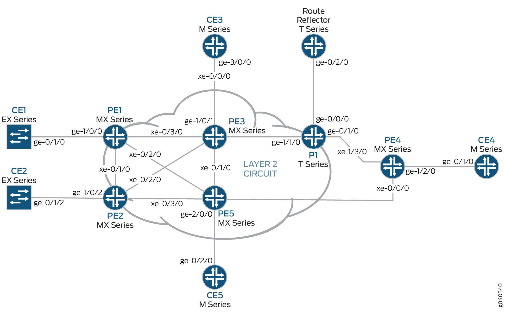
개요 및 토폴로지
구성
모든 구성 세션에서는 명령을 사용하여 commit check 구성을 커밋할 수 있는지 주기적으로 확인하는 것이 좋습니다.
이 예에서 구성된 라우터는 다음 명령 프롬프트를 사용하여 식별됩니다.
CE1고객 에지 1(CE1) 라우터 식별PE1은(는) 프로바이더 에지 1(PE1) 라우터를 식별합니다.CE3고객 에지 3(CE3) 라우터 식별PE3은(는) 프로바이더 에지 3(PE3) 라우터를 식별합니다.CE5고객 에지 5(CE5) 라우터 식별PE5은(는) 프로바이더 에지 5(PE5) 라우터를 식별합니다.
이 예는 다음 섹션에서 구성됩니다.
PE 및 P 라우터에서 프로토콜 구성
단계별 절차
모든 PE 라우터와 P 라우터는 OSPF로 IGP 프로토콜로 구성됩니다. MPLS, LDP 및 BGP 프로토콜은 을 제외한 fxp.0모든 인터페이스에서 활성화됩니다. 코어 대면 인터페이스는 MPLS 주소와 inet 주소로 활성화됩니다.
OSPF를 IGP로 사용하여 모든 PE 및 P 라우터를 구성합니다. 를 제외한
fxp.0모든 인터페이스에서 MPLS, LDP 및 BGP 프로토콜을 활성화합니다. 다음 구성 조각은 라우터 PE1에 대한 프로토콜 구성을 보여줍니다.[edit] protocols { mpls { interface all; interface fxp0.0 { disable; } } bgp { group RR { type internal; local-address 192.0.2.1; family l2vpn { signaling; } neighbor 192.0.2.7; } } ospf { traffic-engineering; area 0.0.0.0 { interface all; interface fxp0.0 { disable; } } } ldp { interface all; interface fxp0.0 { disable; } } }OSPF를 IGP로 사용하여 PE 및 P 라우터를 구성합니다. 를 제외한
fxp.0모든 인터페이스에서 MPLS, LDP 및 BGP 프로토콜을 활성화합니다. 다음 구성 조각은 라우터 PE3에 대한 프로토콜 구성을 보여줍니다.[edit] protocols { mpls { interface all; interface fxp0.0 { disable; } } bgp { group RR { type internal; local-address 192.0.2.3; family l2vpn { signaling; } neighbor 192.0.2.7; } } ospf { traffic-engineering; area 0.0.0.0 { interface all; interface fxp0.0 { disable; } } } ldp { interface all; interface fxp0.0 { disable; } } }
단계별 절차
레이어 2 VPN 프로토콜 및 인터페이스 구성
라우터 PE1에서
ge-1/0/0인터페이스 캡슐화를 구성합니다. 인터페이스 캡슐화를 구성하려면 문을 포함하고encapsulation옵션을 지정ethernet-ccc합니다(vlan-ccc 캡슐화도 지원됨).ge-1/0/0.0서킷 교차 연결 기능을 위한 논리적 인터페이스 패밀리를 구성합니다. 논리적 인터페이스 패밀리를 구성하려면 문을 포함하고family옵션을 지정합니다ccc. 캡슐화는 레이어 2 VPN 도메인의 모든 라우터에 대해 동일한 방식으로 구성되어야 합니다.[edit interfaces] ge-1/0/0 { encapsulation ethernet-ccc; unit 0 { family ccc; } } lo0 { unit 0 { family inet { address 192.0.2.1/24; } } }라우터 PE1에서 레이어 2 VPN 프로토콜을 구성합니다. 원격 사이트 ID를 3으로 구성합니다. 사이트 ID 3은 라우터 PE3(Hub-PE)을 나타냅니다. 레이어 2 VPN 프로토콜을 구성하려면 계층 수준에서 문을
[edit routing-instances routing-instances-name protocols]포함합니다l2vpn. 레이어 2 VPN은 BGP를 신호 프로토콜로 사용합니다.[edit routing-instances] L2VPN { instance-type l2vpn; interface ge-1/0/0.0; route-distinguisher 65000:1; vrf-target target:65000:2; protocols { l2vpn { encapsulation-type ethernet; site CE1 { site-identifier 1; interface ge-1/0/0.0 { remote-site-id 3; } } } } }라우터 PE5에서 문을 포함하여
encapsulation인터페이스 캡슐화를 구성ge-2/0/0하고 옵션을 지정ethernet-ccc합니다. 문을 포함하고family옵션을 지정하여 서킷 교차 연결 기능을 위해 ge-1/0/0.0 논리적 인터페이스 패밀리를ccc구성합니다.[edit interfaces] ge-2/0/0 { encapsulation ethernet-ccc; unit 0 { family ccc; } } lo0 { unit 0 { family inet { address 192.0.2.5/24; } } }라우터 PE5에서 계층 수준에서 문을 포함하여
l2vpn레이어 2 VPN 프로토콜을[edit routing-instances routing-instances-name protocols]구성합니다. 원격 사이트 ID를 로 구성합니다3.[edit routing-instances] L2VPN { instance-type l2vpn; interface ge-2/0/0.0; route-distinguisher 65000:5; vrf-target target:65000:2; protocols { l2vpn { encapsulation-type ethernet; site CE5 { site-identifier 5; interface ge-2/0/0.0 { remote-site-id 3; } } } } }라우터 PE3에서 두 개의 논리적 인터페이스로 인터페이스를 구성
iw0합니다. 인터페이스를iw0구성하려면 문을 포함하고interfaces인터페이스 이름으로 지정iw0합니다. 유닛 0 논리적 인터페이스의 경우, 문을 포함하고peer-unit논리적 인터페이스를 피어 인터페이스unit 1로 지정합니다. 유닛 1 논리적 인터페이스의peer-unit경우, 문을 포함하고 논리적 인터페이스를 피어 인터페이스unit 0로 지정합니다.[edit interfaces] iw0 { unit 0 { encapsulation ethernet-ccc; peer-unit 1; } unit 1 { encapsulation ethernet-ccc; peer-unit 0; } }라우터 PE3에서 문을 포함하고
encapsulation옵션을 지정ethernet-ccc하여 에지 대면ge-1/0/1인터페이스 캡슐화를 구성합니다.[edit interfaces] ge-1/0/1 { encapsulation ethernet-ccc; unit 0 { family ccc; } }라우터 PE3에서 논리적 루프백 인터페이스를 구성합니다. 루프백 인터페이스는 라우터 PE1 및 라우터 PE5에 대상 LDP 세션을 설정하는 데 사용됩니다.
[edit interfaces]
lo0 {
    unit 0 {
        family inet {
            address 192.0.2.3/24;
        }
    }
}
라우터 PE3에서 레이어 2 연동 프로토콜을 활성화합니다. 레이어 2 연동 프로토콜을 활성화하려면 계층 수준에서 문을
[edit protocols]포함합니다l2iw.[edit protocols] l2iw;
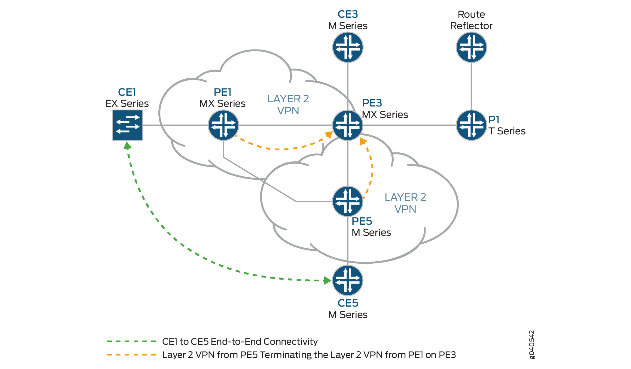
라우터 PE3에서 와 같이 라우터 PE1 및 라우터 PE5에서 레이어 2 VPN 가상 회로를 종료하도록 두 개의 레이어 2 VPN 라우팅 인스턴스를 구성합니다.
[edit routing-instances]
L2VPN-PE1 {
    instance-type l2vpn;
    interface iw0.0;
    route-distinguisher 65000:3;
    vrf-target target:65000:2;
    protocols {
        l2vpn {
            encapsulation-type ethernet;
            site CE3 {
                site-identifier 3;
                interface iw0.0 {
                    remote-site-id 1;
                }
            }
        }
    }
}
L2VPN-PE5 {
    instance-type l2vpn;
    interface iw0.1;
    route-distinguisher 65000:33;
    vrf-target target:65000:2;
    protocols {
        l2vpn {
            encapsulation-type ethernet;
            site CE3 {
                site-identifier 3;
                interface iw0.1 {
                    remote-site-id 5;
                }
            }
        }
    }
}
라우터 PE3에서 레이어 2 VPN에서 레이어 2 VPN 연결 확인
단계별 절차
BGP는 레이어 2 VPN에서 컨트롤 플레인 시그널링에 사용됩니다. 라우터 PE1에서 명령을 사용하여
show bgp레이어 2 VPN에 대한 BGP 컨트롤 플레인이 IP 주소를192.0.2.7가진 경로 리플렉터와의 인접 관계를 설정했는지 확인합니다.토폴로지의 각 PE 라우터에 대한 경로 리플렉터에서 3개의 레이어 2 VPN 경로가 수신됩니다.
user@PE1> show bgp summary
Groups: 1 Peers: 1 Down peers: 0
Table          Tot Paths  Act Paths Suppressed    History Damp State    Pending
bgp.l2vpn.0            3          3          0          0          0          0
Peer                     AS      InPkt     OutPkt    OutQ   Flaps Last Up/Dwn State|#Active/Received/Accepted/Damped...
192.0.2.7               65000        190        192       0       0     1:24:40 Establ
  bgp.l2vpn.0: 3/3/3/0
  L2VPN.l2vpn.0: 3/3/3/0
라우터 PE1에서 명령을 사용하여
show routeBGP 레이어 2 VPN 경로가 각 PE 라우터의L2VPN.l2vpn.0라우팅 테이블 저장되는지 확인합니다.user@PE1> show route table L2VPN.l2vpn.0 L2VPN.l2vpn.0: 4 destinations, 4 routes (4 active, 0 holddown, 0 hidden) + = Active Route, - = Last Active, * = Both 65000:1:1:3/96 *[L2VPN/170/-101] 01:31:53, metric2 1 Indirect 65000:3:3:1/96 *[BGP/170] 01:24:58, localpref 100, from 192.0.2.7 AS path: I > to 10.10.1.2 via xe-0/3/0.0 65000:5:5:3/96 *[BGP/170] 01:24:58, localpref 100, from 192.0.2.7 AS path: I > to 10.10.3.2 via xe-0/2/0.0 65000:33:3:5/96 *[BGP/170] 01:24:58, localpref 100, from 192.0.2.7 AS path: I > to 10.10.1.2 via xe-0/3/0.0라우터 PE1에서 명령을 사용하여
show ldp session대상 LDP 세션이 네트워크의 PE 라우터에 설정되고 상태가Operational인지 확인합니다.user@PE1> show ldp session Address State Connection Hold time 192.0.2.2 Operational Open 24 192.0.2.3 Operational Open 22 192.0.2.5 Operational Open 28
라우터 PE1에서 명령을 사용하여
show l2vpn connections라우터 PE3(Hub-PE)의 사이트 3에 레이어 2 VPN이 있는지 확인합니다Up.user@PE1> show l2vpn connections Layer-2 VPN connections: Legend for connection status (St) EI -- encapsulation invalid NC -- interface encapsulation not CCC/TCC/VPLS EM -- encapsulation mismatch WE -- interface and instance encaps not same VC-Dn -- Virtual circuit down NP -- interface hardware not present CM -- control-word mismatch -> -- only outbound connection is up CN -- circuit not provisioned <- -- only inbound connection is up OR -- out of range Up -- operational OL -- no outgoing label Dn -- down LD -- local site signaled down CF -- call admission control failure RD -- remote site signaled down SC -- local and remote site ID collision LN -- local site not designated LM -- local site ID not minimum designated RN -- remote site not designated RM -- remote site ID not minimum designated XX -- unknown connection status IL -- no incoming label MM -- MTU mismatch MI -- Mesh-Group ID not availble BK -- Backup connection ST -- Standby connection PF -- Profile parse failure PB -- Profile busy Legend for interface status Up -- operational Dn -- down Instance: L2VPN Local site: CE1 (1) connection-site Type St Time last up # Up trans 3 rmt Up Jan 5 18:08:25 2010 1 Remote PE: 192.0.2.3, Negotiated control-word: Yes (Null) Incoming label: 800000, Outgoing label: 800000 Local interface: ge-1/0/0.0, Status: Up, Encapsulation: ETHERNET 5 rmt OR라우터 PE1에서 명령을 사용하여
show route라우팅 테이블 LDP 레이블을 사용하여 트래픽을 전달하는 데 사용되는 레이어 2 VPN 경로로 채워져 있는지mpls.0확인합니다. 이 예에서 라우터는 레이블8000000을(를) 푸시합니다.user@PE1> show route table mpls.0 [edit] mpls.0: 13 destinations, 13 routes (13 active, 0 holddown, 0 hidden) + = Active Route, - = Last Active, * = Both 0 *[MPLS/0] 1w1d 11:36:44, metric 1 Receive 1 *[MPLS/0] 1w1d 11:36:44, metric 1 Receive 2 *[MPLS/0] 1w1d 11:36:44, metric 1 Receive 300432 *[LDP/9] 3d 04:25:02, metric 1 > to 10.10.2.2 via xe-0/1/0.0, Pop 300432(S=0) *[LDP/9] 3d 04:25:02, metric 1 > to 10.10.2.2 via xe-0/1/0.0, Pop 300768 *[LDP/9] 3d 04:25:02, metric 1 > to 10.10.3.2 via xe-0/2/0.0, Pop 300768(S=0) *[LDP/9] 3d 04:25:02, metric 1 > to 10.10.3.2 via xe-0/2/0.0, Pop 300912 *[LDP/9] 3d 04:25:02, metric 1 > to 10.10.3.2 via xe-0/2/0.0, Swap 299856 301264 *[LDP/9] 3d 04:24:58, metric 1 > to 10.10.1.2 via xe-0/3/0.0, Swap 308224 301312 *[LDP/9] 3d 04:25:01, metric 1 > to 10.10.1.2 via xe-0/3/0.0, Pop 301312(S=0) *[LDP/9] 3d 04:25:01, metric 1 > to 10.10.1.2 via xe-0/3/0.0, Pop 800000 *[L2VPN/7] 01:25:28 > via ge-1/0/0.0, Pop Offset: 4 ge-1/0/0.0 *[L2VPN/7] 01:25:28, metric2 1 > to 10.10.1.2 via xe-0/3/0.0, Push 800000 Offset: -4
라우터 PE3에서 레이어 2 VPN에서 레이어 2 VPN 연결 확인
단계별 절차
라우터 PE3에서 명령을 사용하여
show l2vpn connections라우터 PE1 및 라우터 PE5Up의 레이어 2 VPN 연결이 인터페이스를 사용하고iw0있는지 확인합니다.user@PE3> show l2vpn connections Instance: L2VPN-PE1 Local site: CE3 (3) connection-site Type St Time last up # Up trans 1 rmt Up Jan 5 18:08:22 2010 1 Remote PE: 192.0.2.1, Negotiated control-word: Yes (Null) Incoming label: 800000, Outgoing label: 800000 Local interface: iw0.0, Status: Up, Encapsulation: ETHERNET 5 rmt OR Instance: L2VPN-PE5 Local site: CE3 (3) connection-site Type St Time last up # Up trans 1 rmt CN 5 rmt Up Jan 5 18:08:22 2010 1 Remote PE: 192.0.2.5, Negotiated control-word: Yes (Null) Incoming label: 800002, Outgoing label: 800000 Local interface: iw0.1, Status: Up, Encapsulation: ETHERNET라우터 PE3에서 명령을 사용하여
show ldp neighbor대상 LDP 세션 이웃 IP 주소가 표시되는지 확인합니다.user@PE3> show ldp neighbor Address Interface Label space ID Hold time 192.0.2.1 lo0.0 192.0.2.1:0 44 192.0.2.2 lo0.0 192.0.2.2:0 42 192.0.2.4 lo0.0 192.0.2.4:0 31 192.0.2.5 lo0.0 192.0.2.5:0 44
라우터 PE3에서 명령을 사용하여
show bgp summary레이어 2 VPN에 대한 BGP 컨트롤 플레인에서 IP 주소가 있는 경로 리플렉터와의 인접 관계를 설정했는지 확인합니다192.0.2.7.user@PE3> show bgp summary Groups: 1 Peers: 1 Down peers: 0 Table Tot Paths Act Paths Suppressed History Damp State Pending bgp.l2vpn.0 2 2 0 0 0 0 Peer AS InPkt OutPkt OutQ Flaps Last Up/Dwn State|#Active/Received/Accepted/Damped... 192.0.2.7 65000 10092 10195 0 0 3d 4:23:27 Establ bgp.l2vpn.0: 2/2/2/0 L2VPN-PE1.l2vpn.0: 2/2/2/0 L2VPN-PE5.l2vpn.0: 2/2/2/0
라우터 PE3에서 명령을 사용하여
show ldp session대상 LDP 세션이 네트워크의 모든 PE 라우터에 설정되고 상태가Operational인지 확인합니다.user@PE3> show ldp session Address State Connection Hold time 192.0.2.1
OperationalOpen 24 192.0.2.2OperationalOpen 22 192.0.2.4OperationalOpen 20 192.0.2.5OperationalOpen 24라우터 PE3에서 명령을 사용하여
show route라우팅 테이블 LDP 레이블을 사용하여 트래픽을 전달하는 데 사용되는 레이어 2 VPN 경로로 채워져 있는지mpls.0확인합니다. 이 예에서 라우터는 레이블800000을(를) 교체합니다. 또한 레이어 2 상호 연동 경로에 사용되는 두iw0인터페이스를 확인합니다.user@PE3>show route table mpls.0 mpls.0: 16 destinations, 18 routes (16 active, 2 holddown, 0 hidden) + = Active Route, - = Last Active, * = Both 0 *[MPLS/0] 1w1d 11:50:14, metric 1 Receive 1 *[MPLS/0] 1w1d 11:50:14, metric 1 Receive 2 *[MPLS/0] 1w1d 11:50:14, metric 1 Receive 308160 *[LDP/9] 3d 04:38:45, metric 1 > to 10.10.1.1 via xe-0/3/0.0, Pop 308160(S=0) *[LDP/9] 3d 04:38:45, metric 1 > to 10.10.1.1 via xe-0/3/0.0, Pop 308176 *[LDP/9] 3d 04:38:44, metric 1 > to 10.10.6.2 via xe-0/1/0.0, Pop 308176(S=0) *[LDP/9] 3d 04:38:44, metric 1 > to 10.10.6.2 via xe-0/1/0.0, Pop 308192 *[LDP/9] 00:07:18, metric 1 > to 10.10.20.1 via xe-0/0/0.0, Swap 601649 to 10.10.6.2 via xe-0/1/0.0, Swap 299856 308208 *[LDP/9] 3d 04:38:44, metric 1 > to 10.10.5.1 via xe-0/2/0.0, Pop 308208(S=0) *[LDP/9] 3d 04:38:44, metric 1 > to 10.10.5.1 via xe-0/2/0.0, Pop 308224 *[LDP/9] 3d 04:38:42, metric 1 > to 10.10.20.1 via xe-0/0/0.0, Pop 308224(S=0) *[LDP/9] 3d 04:38:42, metric 1 > to 10.10.20.1 via xe-0/0/0.0, Pop 800000 *[L2IW/6] 01:39:13, metric2 1 > to 10.10.6.2 via xe-0/1/0.0, Swap 800000 [L2VPN/7] 01:39:13 > via iw0.0, Pop Offset: 4 800002 *[L2IW/6] 01:39:13, metric2 1 > to 10.10.1.1 via xe-0/3/0.0, Swap 800000 [L2VPN/7] 01:39:13 > via iw0.1, Pop Offset: 4 iw0.0 *[L2VPN/7] 01:39:13, metric2 1 > to 10.10.1.1 via xe-0/3/0.0, Push 800000 Offset: -4 iw0.1 *[L2VPN/7] 01:39:13, metric2 1 > to 10.10.6.2 via xe-0/1/0.0, Push 800000 Offset: -4
단계별 절차
레이어 2 VPN에서 레이어 2 VPN 연결 테스트(CE1에서 CE5까지)
라우터 CE1에서
ping명령을 사용하여 라우터 CE5에 대한 연결을 테스트합니다. 응답 시간이 밀리초 단위이며 핑 응답이 반환되어 있음을 확인합니다.user@CE1>ping 198.51.100.11 PING 198.51.100.11 (198.51.100.11): 56 data bytes 64 bytes from 198.51.100.11: icmp_seq=1 ttl=64 time=22.425 ms 64 bytes from 198.51.100.11: icmp_seq=2 ttl=64 time=1.299 ms 64 bytes from 198.51.100.11: icmp_seq=3 ttl=64 time=1.032 ms 64 bytes from 198.51.100.11: icmp_seq=4 ttl=64 time=1.029 ms
라우터 CE5에서 명령을 사용하여
ping라우터 CE1에 대한 연결을 테스트합니다. 응답 시간이 밀리초 단위이며 핑 응답이 반환되어 있음을 확인합니다.user@CE5>ping 198.51.100.1 PING 198.51.100.1 (198.51.100.1): 56 data bytes 64 bytes from 198.51.100.1: icmp_seq=0 ttl=64 time=1.077 ms 64 bytes from 198.51.100.1: icmp_seq=1 ttl=64 time=0.957 ms 64 bytes from 198.51.100.1: icmp_seq=2 ttl=64 time=1.057 ms 1.017 ms
결과
이 예의 구성 및 검증이 완료되었습니다. 다음 섹션은 참조용입니다.
라우터 PE1에 대한 관련 샘플 구성은 다음과 같습니다.
라우터 PE1
chassis {
    dump-on-panic;
    fpc 1 {
        pic 3 {
            tunnel-services {
                bandwidth 1g;
            }
        }
    }
    network-services ethernet;
}
    interfaces {
        xe-0/1/0 {
            unit 0 {
                family inet {
                    address 10.10.2.1/30;
                }
                family mpls;
            }
        }
        xe-0/2/0 {
            unit 0 {
                family inet {
                    address 10.10.3.1/30;
                }
                family mpls;
            }
        }
        xe-0/3/0 {
            unit 0 {
                family inet {
                    address 10.10.1.1/30;
                }
                family mpls;
            }
        }
        ge-1/0/0 {
            encapsulation ethernet-ccc;
            unit 0 {
                family ccc;
            }
        }
        lo0 {
            unit 0 {
                family inet {
                    address 192.0.2.1/24;
                }
            }
        }
    }
    routing-options {
        static {
            route 172.16.0.0/8 next-hop 172.19.59.1;
        }
        autonomous-system 65000;
    }
    protocols {
        mpls {
            interface all;
            interface fxp0.0 {
                disable;
            }
        }
        bgp {
            group RR {
                type internal;
                local-address 192.0.2.1;
                family l2vpn {
                    signaling;
                }
                neighbor 192.0.2.7;
            }
        }
        ospf {
            traffic-engineering;
            area 0.0.0.0 {
                interface all;
                interface fxp0.0 {
                    disable;
                }
            }
        }
        ldp {
            interface all;
            interface fxp0.0 {
                disable;
            }
        }
    }
    routing-instances {
        L2VPN {
            instance-type l2vpn;
            interface ge-1/0/0.0;
            route-distinguisher 65000:1;
            vrf-target target:65000:2;
            protocols {
                l2vpn {
                    encapsulation-type ethernet;
                    site CE1 {
                        site-identifier 1;
                        interface ge-1/0/0.0 {
                            remote-site-id 3;
                        }
                    }
                }
            }
        }
    }
라우터 PE3에 대한 관련 샘플 구성은 다음과 같습니다.
라우터 PE3
chassis {
    dump-on-panic;
    fpc 1 {
        pic 3 {
            tunnel-services {
                bandwidth 1g;
            }
        }
    }
    network-services ethernet;
}
interfaces {
    xe-0/0/0 {
        unit 0 {
            family inet {
                address 10.10.20.2/30;
            }
            family mpls;
        }
    }
    xe-0/1/0 {
        unit 0 {
            family inet {
                address 10.10.6.1/30;
            }
            family mpls;
        }
    }
    xe-0/2/0 {
        unit 0 {
            family inet {
                address 10.10.5.2/30;
            }
            family mpls;
        }
    }
    xe-0/3/0 {
        unit 0 {
            family inet {
                address 10.10.1.2/30;
            }
            family mpls;
        }
    }
    ge-1/0/1 {
        encapsulation ethernet-ccc;
        unit 0 {
            family ccc;
        }
    }
    iw0 {
        unit 0 {
            encapsulation ethernet-ccc;
            peer-unit 1;
        }
        unit 1 {
            encapsulation ethernet-ccc;
            peer-unit 0;
        }
    }
    lo0 {
        unit 0 {
            family inet {
                address 192.0.2.3/24;
            }
        }
    }
}
routing-options {
    static {
        route 172.16.0.0/8 next-hop 172.19.59.1;
    }
    autonomous-system 65000;
}
protocols {
    l2iw;
    mpls {
        interface all;
        interface fxp0.0 {
            disable;
        }
    }
    bgp {
        group RR {
            type internal;
            local-address 192.0.2.3;
            family l2vpn {
                signaling;
            }
            neighbor 192.0.2.7;
        }
    }
    ospf {
        area 0.0.0.0 {
            interface all;
            interface fxp0.0 {
                disable;
            }
        }
    }
    ldp {
        interface all;
        interface fxp0.0 {
            disable;
        }
    }
}
routing-instances {
    L2VPN-PE1 {
        instance-type l2vpn;
        interface iw0.0;
        route-distinguisher 65000:3;
        vrf-target target:65000:2;
        protocols {
            l2vpn {
                encapsulation-type ethernet;
                site CE3 {
                    site-identifier 3;
                    interface iw0.0 {
                        remote-site-id 1;
                    }
                }
            }
        }
    }
    L2VPN-PE5 {
        instance-type l2vpn;
        interface iw0.1;
        route-distinguisher 65000:33;
        vrf-target target:65000:2;
        protocols {
            l2vpn {
                encapsulation-type ethernet;
                site CE3 {
                    site-identifier 3;
                    interface iw0.1 {
                        remote-site-id 5;
                    }
                }
            }
        }
    }
}