예: 레이어 2 서킷에 대한 VCCV의 BFD 구성
이 예는 데이터 경로에서 장애를 더 빠르게 감지할 수 있도록 레이어 2 서킷에 대한 VCCV의 BFD를 구성하는 방법을 보여줍니다.
요구 사항
이 예에서 사용되는 하드웨어 및 소프트웨어 구성 요소는 다음과 같습니다.
2개의 MX 시리즈 5G 유니버설 라우팅 플랫폼
모든 디바이스에서 실행되는 Junos OS 릴리스 12.1 이상
개요
Junos OS 릴리스 12.1부터 가상 서킷 연결 검증(VCCV)을 위한 BFD(Bidirectional Forwarding Detection) 지원을 통해 유사 회선에 대한 제어 채널을 구성할 수 있으며, 해당 제어 채널에서 사용할 해당 운영 및 관리 기능을 구성할 수 있습니다. BFD는 유사 회선 데이터 경로를 지속적으로 모니터링하고 데이터 플레인 오류를 감지하기 위한 리소스 부족 메커니즘을 제공합니다. 이 기능은 RFC 5885, 유사 회선 가상 회로 연결 검증(VCCV)에 대한 BFD(Bidirectional Forwarding Detection)에 설명된 대로 VCCV에 대한 비동기 모드 BFD를 지원합니다. 또한 ping을 사용하여 유사 회선 장애를 감지할 수 있습니다. 그러나 ping에 필요한 처리 리소스는 BFD에 필요한 것보다 큽니다. 또한 BFD는 VCCV 핑보다 더 빠르게 데이터 플레인 장애를 감지할 수 있습니다. 유사 회선에 대한 BFD는 레이어 2 서킷(LDP 기반)에서 지원됩니다.
레이어 2 서킷에 대한 VCCV의 BFD를 구성하려면 계층 수준에서 [edit protocols l2circuit neighbor address interface interface-name] 구성 문을 구성 oam 합니다. control-channel 계층 수준의 구성 문 [edit routing-instances routing-instance-name protocols l2vpn oam] 은 레이어 2 서킷 구성에 적용되지 않습니다.
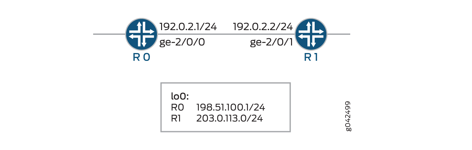
토폴로지
토폴로지에서 레이어 2 서킷에 대한 VCCV에 대한 BFD는 디바이스 R0에서 구성됩니다.
구성
CLI 빠른 구성
이 예를 빠르게 구성하려면, 아래 명령을 복사하여 텍스트 파일로 붙여 넣은 다음 모든 라인브레이크를 제거하고, 네트워크 구성을 일치하는 데 필요한 세부 사항을 변경하고, 계층 수준에서 [edit] 명령을 복사하여 CLI에 붙여 넣은 다음, 구성 모드에서 들어갑니다 commit .
R0
set chassis redundancy graceful-switchover
set interfaces ge-1/1/9 vlan-tagging
set interfaces ge-1/1/9 encapsulation vlan-ccc
set interfaces ge-1/1/9 unit 0 encapsulation vlan-ccc
set interfaces ge-1/1/9 unit 0 vlan-id 512
set interfaces ge-2/0/0 unit 0 family inet address 192.0.2.1/24
set interfaces ge-2/0/0 unit 0 family mpls
set interfaces lo0 unit 0 family inet address 198.51.100.0/24
set routing-options nonstop-routing
set routing-options static route 203.0.113.0/24 next-hop 192.0.2.2
set routing-options router-id 198.51.100.0
set protocols rsvp interface ge-2/0/0.0
set protocols mpls label-switched-path lsp1 to 203.0.113.0
set protocols mpls interface ge-2/0/0.0
set protocols ospf traffic-engineering
set protocols ospf area 0.0.0.0 interface ge-2/0/0.0
set protocols ldp interface all
set protocols l2circuit neighbor 203.0.113.0 interface ge-1/1/9.0 virtual-circuit-id 1
set protocols l2circuit neighbor 203.0.113.0 interface ge-1/1/9.0 oam bfd-liveness-detection minimum-interval 300
set protocols l2circuit neighbor 203.0.113.0 interface ge-1/1/9.0 oam bfd-liveness-detection minimum-receive-interval 10
set protocols l2circuit neighbor 203.0.113.0 interface ge-1/1/9.0 oam bfd-liveness-detection multiplier 3
set protocols l2circuit neighbor 203.0.113.0 interface ge-1/1/9.0 oam bfd-liveness-detection transmit-interval minimum-interval 5
set protocols l2circuit neighbor 203.0.113.0 interface ge-1/1/9.0 oam bfd-liveness-detection transmit-interval threshold 30
set protocols l2circuit neighbor 203.0.113.0 interface ge-1/1/9.0 oam bfd-liveness-detection detection-time threshold 40
R1
set interfaces ge-1/1/9 vlan-tagging
set interfaces ge-1/1/9 encapsulation vlan-ccc
set interfaces ge-1/1/9 unit 0 encapsulation vlan-ccc
set interfaces ge-1/1/9 unit 0 vlan-id 512
set interfaces ge-2/0/1 unit 0 family inet address 192.0.2.2/24
set interfaces ge-2/0/1 unit 0 family mpls
set interfaces lo0 unit 0 family inet address 203.0.113.0/24
set routing-options static route 198.51.100.0/24 next-hop 192.0.2.1
set routing-options router-id 203.0.113.0
set protocols rsvp interface ge-2/0/1.0
set protocols mpls label-switched-path lsp2 to 198.51.100.0
set protocols mpls interface ge-2/0/1.0
set protocols ospf traffic-engineering
set protocols ospf area 0.0.0.0 interface ge-2/0/1.0
set protocols ldp interface all
set protocols l2circuit neighbor 198.51.100.0 interface ge-1/1/9.0 virtual-circuit-id 1
set protocols l2circuit neighbor 198.51.100.0 interface ge-1/1/9.0 oam bfd-liveness-detection minimum-interval 300
set protocols l2circuit neighbor 198.51.100.0 interface ge-1/1/9.0 oam bfd-liveness-detection minimum-receive-interval 10
set protocols l2circuit neighbor 198.51.100.0 interface ge-1/1/9.0 oam bfd-liveness-detection multiplier 3
set protocols l2circuit neighbor 198.51.100.0 interface ge-1/1/9.0 oam bfd-liveness-detection transmit-interval minimum-interval 5
set protocols l2circuit neighbor 198.51.100.0 interface ge-1/1/9.0 oam bfd-liveness-detection transmit-interval threshold 30
set protocols l2circuit neighbor 198.51.100.0 interface ge-1/1/9.0 oam bfd-liveness-detection detection-time threshold 40
디바이스 R0 구성
단계별 절차
다음 예에서는 구성 계층에서 다양한 수준을 탐색해야 합니다. CLI 탐색에 대한 정보는 CLI 사용자 가이드의 구성 모드에서 CLI 편집기 사용을 참조하십시오.
디바이스 R0 구성:
디바이스에 대한 적절한 인터페이스 이름, 주소 및 기타 매개 변수를 수정한 후 디바이스 R1에 대해 이 절차를 반복합니다.
graceful switchover 중복을 구성합니다.
[edit chassis]
user@R0# set redundancy graceful-switchover
인터페이스를 구성합니다.
[edit interfaces]
user@R0# set ge-1/1/9 vlan-tagging
user@R0# set ge-1/1/9 encapsulation vlan-ccc
user@R0# set ge-1/1/9 unit 0 encapsulation vlan-ccc
user@R0# set ge-1/1/9 unit 0 vlan-id 512
user@R0# set ge-2/0/0 unit 0 family inet address 192.0.2.1/24
user@R0# set ge-2/0/0 unit 0 family mpls
user@R0# set lo0 unit 0 family inet address 198.51.100.0/24
논스톱 라우팅 옵션, 정적 경로, 라우터 ID 라우팅 옵션을 구성합니다.
[edit routing-options]
user@R0# set nonstop-routing
user@R0# set static route 203.0.113.0/24 next-hop 192.0.2.2
user@R0# set router-id 198.51.100.0
RSVP 프로토콜을 구성합니다.
[edit protocols rsvp]
user@R0# set interface ge-2/0/0.0
MPLS 프로토콜을 구성합니다.
[edit protocols mpls]
user@R0# set label-switched-path lsp1 to 203.0.113.0
user@R0# set interface ge-2/0/0.0
OSPF 프로토콜을 구성합니다.
[edit protocols ospf]
user@R0# set traffic-engineering
user@R0# set area 0.0.0.0 interface ge-2/0/0.0
LDP 프로토콜을 구성합니다.
[edit protocols ldp]
user@R0# set interface all
레이어 2 서킷 프로토콜의 인접 라우터에 대한 가상 서킷 ID를 구성합니다.
[edit protocols l2circuit]
user@R0# set neighbor 203.0.113.0 interface ge-1/1/9.0 virtual-circuit-id 1
레이어 2 서킷 프로토콜의 oam 속성을 구성합니다.
[edit protocols l2circuit]
user@R0# set neighbor 203.0.113.0 interface ge-1/1/9.0 oam bfd-liveness-detection minimum-interval 300
user@R0# set neighbor 203.0.113.0 interface ge-1/1/9.0 oam bfd-liveness-detection minimum-receive-interval 10
user@R0# set neighbor 203.0.113.0 interface ge-1/1/9.0 oam bfd-liveness-detection multiplier 3
user@R0# set neighbor 203.0.113.0 interface ge-1/1/9.0 oam bfd-liveness-detection transmit-interval minimum-interval 5
user@R0# set neighbor 203.0.113.0 interface ge-1/1/9.0 oam bfd-liveness-detection transmit-interval threshold 30
user@R0# set neighbor 203.0.113.0 interface ge-1/1/9.0 oam bfd-liveness-detection detection-time threshold 40
결과
구성 모드에서 , show interfaces, show protocols및 show routing-options 명령을 show chassis입력하여 구성을 확인합니다. 출력에 의도한 구성이 표시되지 않으면 이 예의 지침을 반복하여 구성을 수정합니다.
user@R0# show chassis
redundancy {
    graceful-switchover;
}
user@R0# show interfaces
ge-1/1/9 {
    vlan-tagging;
    encapsulation vlan-ccc;
    unit 0 {
        encapsulation vlan-ccc;
        vlan-id 512;
    }
}
ge-2/0/0 {
    unit 0 {
        family inet {
            address 192.0.2.1/24;
        }
        family mpls;
    }
}
lo0 {
    unit 0 {
        family inet {
            address 198.51.100.0/24;
        }
    }
}
user@R0# show protocols
rsvp {
    interface ge-2/0/0.0;
}
mpls {
    label-switched-path lsp1 {
        to 203.0.113.0;
    }
    interface ge-2/0/0.0;
}
ospf {
    traffic-engineering;
    area 0.0.0.0 {
        interface ge-2/0/0.0;
    }
}
ldp {
    interface all;
}
l2circuit {
    neighbor 203.0.113.0 {
        interface ge-1/1/9.0 {
            virtual-circuit-id 1;
            oam {
                bfd-liveness-detection {
                    minimum-interval 300;
                    minimum-receive-interval 10;
                    multiplier 3;
                    transmit-interval {
                        minimum-interval 5;
                        threshold 30;
                    }
                    detection-time {
                        threshold 40;
                    }
                }
            }
        }
    }
}
user@R0# show routing-options
nonstop-routing;
static {
    route 203.0.113.0/24 next-hop 192.0.2.2;
}
router-id 198.51.100.0;
디바이스 구성이 완료되면 구성 모드에서 들어갑니다 commit .
검증
구성이 제대로 작동하고 있는지 확인합니다.
레이어 2 서킷 연결 확인
목적
레이어 2 회로에서 연결을 확인합니다.
작업
운영 모드에서 디바이스 R0에 show l2circuit connections 대한 명령을 실행합니다.
user@R0> show l2circuit connections

Layer-2 Circuit Connections:

Legend for connection status (St)
EI -- encapsulation invalid      NP -- interface h/w not present
MM -- mtu mismatch               Dn -- down
EM -- encapsulation mismatch     VC-Dn -- Virtual circuit Down
CM -- control-word mismatch      Up -- operational
VM -- vlan id mismatch           CF -- Call admission control failure
OL -- no outgoing label          IB -- TDM incompatible bitrate
NC -- intf encaps not CCC/TCC    TM -- TDM misconfiguration
BK -- Backup Connection          ST -- Standby Connection
CB -- rcvd cell-bundle size bad  SP -- Static Pseudowire
LD -- local site signaled down   RS -- remote site standby
RD -- remote site signaled down  HS -- Hot-standby Connection
XX -- unknown

Legend for interface status
Up -- operational
Dn -- down
Neighbor: 203.0.113.0
    Interface                 Type  St     Time last up          # Up trans
    ge-1/1/9.0(vc 1)          rmt   Up     Jun  2 03:19:44 2014           1
      Remote PE: 203.0.113.0, Negotiated control-word: Yes (Null)
      Incoming label: 299792, Outgoing label: 299792
      Negotiated PW status TLV: No
      Local interface: ge-1/1/9.0, Status: Up, Encapsulation: VLAN
      Flow Label Transmit: No, Flow Label Receive: No
      Flow Label Transmit: No, Flow Label Receive: No
의미
출력에는 디바이스 R0에서 이웃으로의 레이어 2 가상 서킷 정보가 표시됩니다.
BFD 세션 확인
목적
BFD 세션을 확인합니다.
작업
운영 모드에서 디바이스 R0에 show bfd session 대한 명령을 실행합니다.
user@R0> show bfd session

                                                  Detect   Transmit
Address                  State     Interface      Time     Interval  Multiplier

203.0.113.7                Up        ge-2/0/0.0     0.030     0.010        3

1 sessions, 1 clients
Cumulative transmit rate 100.0 pps, cumulative receive rate 100.0 pps
의미
출력은 주소와 BFD 세션이 활성화된 인터페이스를 보여줍니다. 상태 Up 는 BFD 세션이 작동 중임을 나타냅니다. BFD 세션은 BFD 제어 패킷을 탐지하는 데 30밀리초의 시간 간격을 갖고, 전송 시스템은 BFD 제어 패킷을 전송하는 데 10밀리초의 시간 간격을 가지며, 전송 시스템은 시간 간격을 곱 3 하여 탐지 시간을 결정합니다. 총 활성 BFD 세션 수 및 활성 BFD 세션을 호스팅하는 총 클라이언트 수입니다. 누적 전송 속도는 모든 활성 세션에서 초당 전송된 총 BFD 제어 패킷 수를 나타내고, 누적 수신 속도는 모든 활성 세션에서 초당 수신된 총 BFD 제어 패킷 수를 나타냅니다.
자세한 BFD 세션 정보 확인
목적
자세한 BFD 세션 정보를 확인합니다.
작업
운영 모드에서 디바이스 R0에 show bfd session extensive 대한 명령을 실행합니다.
user@R0> show bfd session extensive

                                                  Detect   Transmit
Address                  State     Interface      Time     Interval  Multiplier

203.0.113.7                Up        ge-2/0/0.0     0.030     0.010        3
 Client L2CKT-OAM, TX interval 0.005, RX interval 0.010
 Session up time 03:47:14
 Local diagnostic None, remote diagnostic None
 Remote state Up, version 1
 Replicated
 Session type: VCCV BFD
 Min async interval 0.005, min slow interval 1.000
 Adaptive async TX interval 0.005, RX interval 0.010
 Local min TX interval 0.005, minimum RX interval 0.010, multiplier 3
 Remote min TX interval 0.005, min RX interval 0.010, multiplier 3
 Threshold transmission interval 0.030, Threshold for detection time 0.040
 Local discriminator 20, remote discriminator 13004
 Echo mode disabled/inactive
 Remote is control-plane independent
 Neighbor address 203.0.113.0, Virtual circuit id 1
  Session ID: 0x0

1 sessions, 1 clients
Cumulative transmit rate 100.0 pps, cumulative receive rate 100.0 pps
의미
출력에는 BFD 세션에 대한 자세한 정보가 표시됩니다.