예: PTX 라우터에서 원격 포트 미러링 구성
이 예는 Junos Evolved를 실행하는 PTX 플랫폼에서 원격 포트 미러링을 구성하고 확인하는 방법을 보여줍니다. PTX 플랫폼에는 PTX10004, PTX10008 및 PTX10016 섀시의 PTX10001-36MR, LC1201 및 LCPTX100016이 포함됩니다.
시작하기 전에
| 하드웨어 및 소프트웨어 요구 사항 | Junos OS Evolved 릴리스 22.2R1.12-EVO 이상. PTX10001-36MR 지원되는 플랫폼 및 Junos OS 버전의 전체 목록은 기능 탐색기를 참조하십시오. |
| 예상 읽기 시간 |
15분. |
| 예상 구성 시간 |
30분 |
| 비즈니스 영향 |
포트 미러링은 디버깅 및 보안 관련 작업에 중요한 도구입니다. 미러링된 트래픽은 프로토콜 상호 작용, 이상 징후 탐지 또는 합법적 가로채기 도청 작업을 분석하는 다양한 도구를 통해 오프라인에서 분석할 수 있습니다. |
| 자세히 알아보기 |
포트 미러링을 더 잘 이해하려면 포트 미러링 및 분석기를 참조하십시오 |
| 더 알아보세요 |
학습 포털 |
기능 개요
원격 포트 미러링 기능 개요는 이 예에 구축된 프로토콜 및 기술에 대한 간략한 요약을 제공합니다.
| 라우팅 및 신호 전송 프로토콜 |
|
| OSPF 및 OSPF3 |
모든 라우터는 OSPF 및 OSPF3를 IGP로 실행합니다. 모든 프로바이더 라우터는 영역 0(백본 영역이라고도 함)에 속합니다. OSPF/OSPF3 라우팅 도메인은 토폴로지의 모든 네트워크와 인터페이스에 내부 도달 가능성을 제공합니다. CE 라우터는 OSPF 및 OSPF3를 사용하여 PE와 경로를 교환합니다. |
| MPLS 및 RSVP | 공급자 라우터는 RSVP 프로토콜을 사용하여 MPLS LSP에 신호를 보냅니다. IPv6 터널링은 MPLS를 통한 IPv6을 지원하기 위해 활성화됩니다. MPLS는 레이어 3 VPN을 지원하는 데 사용됩니다. |
| MP-BGP | 멀티프로토콜 BGP는 고객 VPN 경로를 보급하기 위해 PE 라우터 간에 사용됩니다. |
| 레이어 3 VPN | PE 라우터는 VRF 라우팅 인스턴스를 사용하여 CE 라우터를 위한 레이어 3 VPN 서비스로 지원합니다. 고객 트래픽은 RSVP 신호 LSP의 코어를 통해 전송됩니다. MPLS 기반 L3 VPN의 작동에 대한 자세한 내용은 예: 기본 MPLS 기반 레이어 3 VPN 구성을 참조하십시오. |
| 라우팅 프로토콜 |
|
| IPv4 및 IPv6 |
모든 라우터는 IPv4와 IPv6의 라우팅을 모두 지원하도록 구성됩니다. |
| 분석기(모니터링 스테이션) |
|
| Centos 및 Wireshark |
분석기는 Wireshark의 GUI 버전과 함께 Centos 7.x를 실행합니다. |
토폴로지 개요
이 예는 MPLS 기반 L3 VPN의 컨텍스트를 사용하여 PTX 라우터의 원격 포트 미러링 기능을 보여줍니다. L3 VPN은 고객 에지(CE)와 프로바이더 에지(PE) 라우터 간의 IPv4 및 IPv6 트래픽을 모두 지원하도록 구성됩니다.
| 라우터 이름 | 역할 |
기능 |
| CE | 포트 미러링이 제대로 작동하는지 확인하기 위해 테스트 트래픽을 전송하는 고객 에지(CE) 라우터. | 이러한 라우터는 CE 라우터로 지정됩니다. CE 라우터는 공급자 네트워크에서 L3 VPN 서비스를 얻습니다. CE는 공급자 라우터와 동일한 최단 경로 우선(OSPF) 라우팅 도메인을 공유하지 않습니다. |
| PE | CE에 연결된 프로바이더 에지(PE) 라우터. | PE는 프로바이더 네트워크의 에지에 있습니다. 주니퍼의 PE는 라우팅 인스턴스, MP-BGP, RSVP 및 MPLS 데이터 플레인을 사용하여 레이어 3 VPN을 지원합니다. PE1 라우터는 DUT(DUT를) 미러링하는 원격 포트 중 하나로 작동합니다. |
| P | 프로바이더(P) 코어 라우터. | P 라우터는 BGP-free 프로바이더 코어 라우터를 나타냅니다. OSPF, OSPF3 및 MPLS 전송을 지원합니다. BGP를 실행하거나 VPN 상태를 전달하지 않습니다. P 라우터는 원격 포트 미러링 DUT 중 하나의 기능을 합니다. |
| 분석기 | 분석기 디바이스는 저장 및 분석을 위해 미러링 트래픽을 수신합니다. | 분석기의 세부 사항은 이 문서의 범위를 벗어납니다. 다양한 오픈 소스 및 상업용 옵션을 사용할 수 있습니다. 우리의 분석기는 Wireshark의 GUI 버전을 지원하는 Gnome 데스크톱과 함께 Centos 7.x를 실행하고 있습니다. |
토폴로지 일러스트레이션
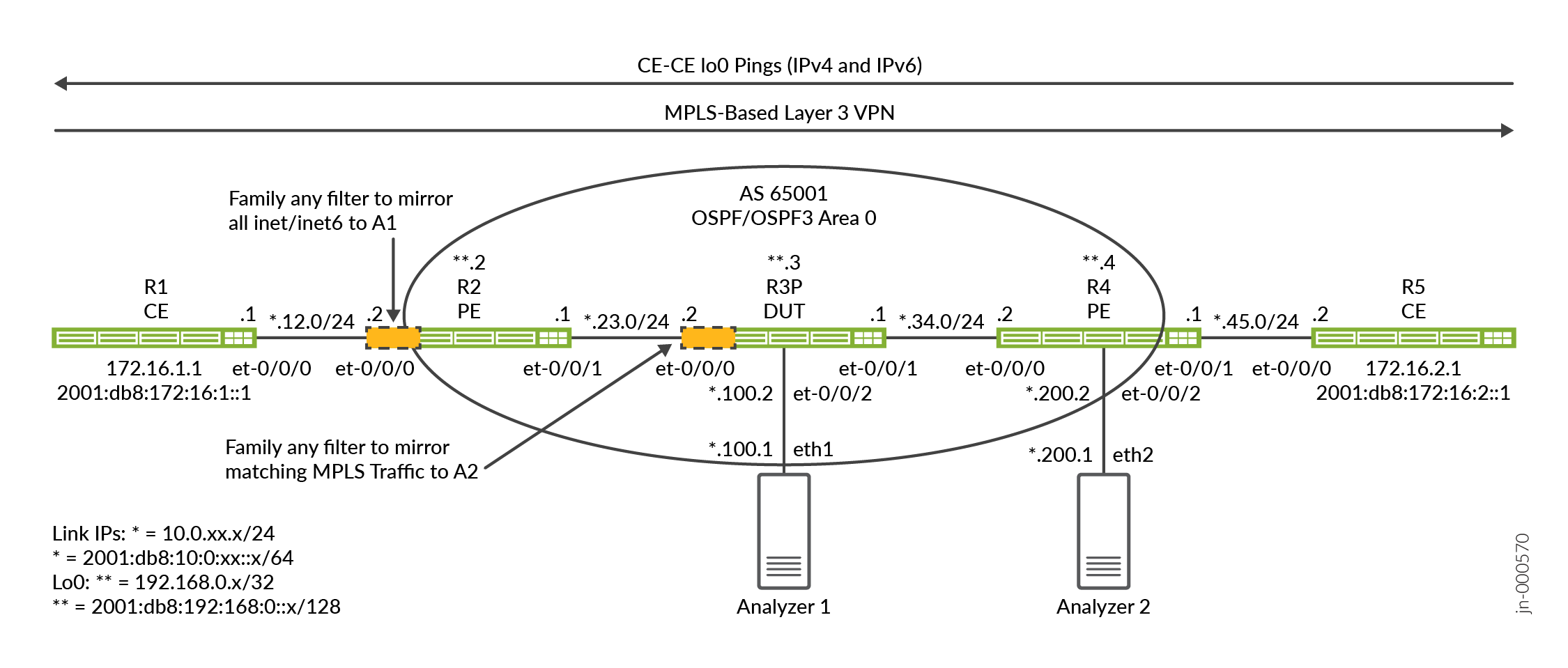
이 예는 프로바이더 네트워크를 통해 전송되는 CE 트래픽을 미러링하는 두 가지 방법을 보여줍니다.
-
첫 번째 방법은 PE-CE VRF 인터페이스에서 모두 일치 필터를 사용합니다.
-
두 번째 방법은 공급자(P) 라우터에 적용되는 MPLS 레이블 일치 필터를 보여줍니다.
PE1 라우터(R2)와 P 라우터(R3)는 원격 포트 미러링이 구성되고 DUT로 작동하는 라우터입니다. 이러한 라우터는 제품군 any 방화벽 필터를 사용하여 포트 미러링을 위해 일부 트래픽을 일치시킵니다. 수신 및 송신 필터의 조합은 CE 라우터(R1 및 R5) 사이의 요청 및 응답 트래픽 흐름을 모두 미러링하는 데 사용됩니다.
원격 포트 미러링은 GRE 캡슐화를 위한 터널을 사용하여 미러링된 트래픽을 원격 분석기 디바이스로 보냅니다. 토폴로지에는 두 개의 분석기가 있습니다. 하나는 R2/PE1 라우터에 연결되고 다른 하나는 R3/P 라우터에 연결됩니다. 이를 통해 CE 트래픽을 미러링하는 두 가지 방법, 하나는 PE에서, 다른 하나는 코어 P 라우터에서 시연할 수 있습니다. 패킷 캡처 및 분석을 위해 Wireshark와 함께 Centos 호스트를 사용합니다.
PTX 플랫폼은 fti(Flexible Tunnel Interface) 인프라를 사용하여 다양한 터널링 애플리케이션을 지원합니다. 원격 포트 미러링의 경우, GRE 터널은 미러링된 트래픽을 원격 분석기 디바이스로 전송하기 위해 FTI 인터페이스에 구성됩니다. 이 예제의 일부로 미러링할 트래픽을 선택하는 FTI 기반 GRE 터널, 미러링 인스턴스 및 방화벽 필터를 구성합니다.
R2/PE1 구성 단계
CLI 탐색에 대한 정보는 구성 모드에서 CLI 편집기 사용을 참조하십시오
모든 라우터에 대한 전체 구성은 다음을 참조하십시오. 부록 2: 모든 라우터에서 명령 설정
이 섹션에서는 이 예에서 PE1/R2 라우터를 구성하는 데 필요한 구성 작업을 중점적으로 설명합니다. 부록에서 모든 라우터에 대한 전체 구성을 제공합니다. 1단계에서는 이 예의 기준선을 요약합니다. 이 기준은 IPv4 및 IPv6 연결, MPLS 및 레이어 3 VPN으로 구성됩니다. 이 예에서는 원격 포트 미러링의 구성 및 검증에 중점을 둡니다.
L3 VPN 작동 및 기본 구성에 대한 자세한 내용은 예: 기본 MPLS 기반 레이어 3 VPN을 구성합니다.
-
PE1 라우터에서 IP 라우팅 및 L3 VPN 기준선을 구성합니다. 여기에는 다음이 포함됩니다.
-
IPv4 및 IPv6 모두에 대한 인터페이스 번호 매김 및 코어 대면 인터페이스에 대한 지원 포함
family mpls. -
모든 네트워크 인터페이스 간의 도달 가능성을 제공하도록 OSPF 및 OSPFv3 라우팅 프로토콜을 구성합니다.
-
L3 VPN 트래픽을 지원하기 위한 RSVP 및 MPLS 레이블 스위치 경로(LSP).
-
PE 라우터의 주소 패밀리를
inet-vpnandinet6-vpn[edit] set interfaces et-0/0/0 unit 0 family inet address 10.0.12.2/24 set interfaces et-0/0/0 unit 0 family inet6 address 2001:db8:10:0:12::2/64 set interfaces et-0/0/1 unit 0 family inet address 10.0.23.1/24 set interfaces et-0/0/1 unit 0 family inet6 address 2001:db8:10:0:23::1/64 set interfaces et-0/0/1 unit 0 family mpls set interfaces lo0 unit 0 family inet address 192.168.0.2/32 set interfaces lo0 unit 0 family inet6 address 2001:db8:192:168:0::2/128 set policy-options policy-statement ospf-export term 1 from protocol bgp set policy-options policy-statement ospf-export term 1 then accept set routing-instances ce1 instance-type vrf set routing-instances ce1 protocols ospf area 0.0.0.0 interface all set routing-instances ce1 protocols ospf export ospf-export set routing-instances ce1 protocols ospf3 area 0.0.0.0 interface all set routing-instances ce1 protocols ospf3 export ospf-export set routing-instances ce1 interface et-0/0/0.0 set routing-instances ce1 route-distinguisher 65001:1 set routing-instances ce1 vrf-target target:65001:100 set routing-instances ce1 vrf-table-label set routing-options router-id 192.168.0.2 set routing-options autonomous-system 65001 set protocols bgp group ibgp type internal set protocols bgp group ibgp local-address 192.168.0.2 set protocols bgp group ibgp family inet unicast set protocols bgp group ibgp family inet-vpn unicast set protocols bgp group ibgp family inet6-vpn unicast set protocols bgp group ibgp neighbor 192.168.0.4 set protocols mpls label-switched-path pe2 to 192.168.0.4 set protocols mpls label-switched-path pe2 no-cspf set protocols mpls ipv6-tunneling set protocols mpls interface all set protocols mpls interface fxp0.0 disable set protocols ospf area 0.0.0.0 interface all set protocols ospf area 0.0.0.0 interface fxp0.0 disable set protocols ospf3 area 0.0.0.0 interface all set protocols ospf3 area 0.0.0.0 interface fxp0.0 disable set protocols rsvp interface all set protocols rsvp interface fxp0 disable
기준선을 다루었으므로 나머지 단계는 CE1을 향하는 VRF 인터페이스에서 송수신된 모든 트래픽을 포트 미러링하도록 R2/PE1 라우터를 구성하는 데 중점을 둡니다.
-
- GRE 터널 구성부터 시작합니다. PTX 라우터에서 터널은 FTI 인터페이스를 통해 구현됩니다. GRE 터널 소스에서 또는 GRE 터널 소스로 향하는 진단 핑 테스트를 수행할 것으로 예상하지 않는 한 GRE 터널의 소스 주소는 라우팅 가능할 필요가 없습니다. PE1에 의해 미러링된 트래픽의 GRE 대상은 분석기 1 라우터입니다. 미러 트래픽이 분석기로 전송되려면 이 대상에 도달할 수 있어야 합니다. 패시브 IGP 인스턴스를 사용하여 분석기 네트워크에 대한 IGP 연결성을 보장합니다.
대상 주소는 P/R3 라우터의 et-0/0/2 인터페이스에 연결된 분석기 1 디바이스에 매핑됩니다. PTX에서 원격 포트 미러링을 지원하려면 FTI 논리적 인터페이스를 구성해야 합니다.
family ccc이는 미러링 동작이 레이어 2에서 발생하기 때문입니다.set interfaces fti0 unit 1 description "GRE tunnel for remote port mirror" set interfaces fti0 unit 1 tunnel encapsulation gre source address 10.100.0.1 set interfaces fti0 unit 1 tunnel encapsulation gre destination address 10.0.100.1 set interfaces fti0 unit 1 family ccc
참고:패시브 IGP 인스턴스는 분석기 디바이스에 연결된 인터페이스에 대해 프로비저닝됩니다. 이는 GRE 캡슐화된 미러링 트래픽에 대한 분석기 포트에 대한 IGP 도달 가능성을 제공합니다. 패시브 설정은 캡처를 복잡하게 만들 수 있으므로 분석기에 hello 패킷이 생성되는 것을 방지합니다.
또한 진단 테스트의 지원을 위해 핑에 응답할 수 있도록 분석기 디바이스에 정적 경로를 구성했습니다. 엄밀히 말하면, 원격 포트 미러링이 작동하려면 DUT와 분석기 사이에 단순 연결 또는 라우팅만 필요합니다.
- 샘플링 인스턴스를 구성합니다. 일치하는 모든 패킷을 샘플링하기 위해 속도 1을 사용합니다. 일치하는 모든 트래픽이 이미 샘플링된 경우 기본값
run-length인 1은 그대로 유지됩니다. 미러 트래픽을 전송하는 데 사용되는 FTI 라우터에서 논리적 인터페이스를 지정해야 합니다. 이전 단계에서 GRE 터널에 대한 fti0 인터페이스에 구성unit 1했으므로 동일한 인터페이스와 단위가 미러 인스턴스의 출력 인터페이스로 지정됩니다.[edit] set forwarding-options port-mirroring instance pe-mirror input rate 1 set forwarding-options port-mirroring instance pe-mirror family any output interface fti0.1
참고:옵션을 사용하여 계층에서
[edit forwarding-options port-mirroring instance instance-name input]미러링된 트래픽의 최대 패킷 길이를maximum-packet-length지정할 수 있습니다. 기본적으로 패킷 길이는 0이며, 이는 전체 패킷이 미러링된다는 것을 의미합니다. -
CE 트래픽을 일치시키고 미러링할 두 개의 제품군
any방화벽 필터를 정의합니다. 두 개의 필터가 정의되어 있는데, 하나는 CE1에서 CE2로의 트래픽 미러링을 위한 것이고 다른 하나는 CE2에서 CE1로의 미러링을 위한 것입니다. 필터에는 검증을 지원하는 카운트 함수가 포함되어 있습니다. 포트 미러링 작업은 이전에 구성한 포트 미러링 인스턴스로 일치하는 트래픽을 지시합니다.패밀리
any필터는 레이어 2와 레이어 3 매칭을 모두 지원합니다. 전자의 경우 VLAN ID, 인터페이스, MAC 주소 또는 MPLS 레이블에서 일치시킬 수 있습니다. 후자의 경우 표준 IPv4 또는 IPv6 헤더 필드에서 일치시킬 수 있습니다.토폴로지를 감안할 때 CE에서 보내거나 받은 모든 트래픽을 포착하는 모두 일치 용어를 사용합니다. 여기에는 IPv4, IPv6, ARP, LLDP 및 OSPF와 같은 모든 라우팅 프로토콜이 포함됩니다.
[edit]
set firewall family any filter ce1-ce2 term mirror-ce1-ce2 then count ce1-ce2-mirror
set firewall family any filter ce1-ce2 term mirror-ce1-ce2 then port-mirror-instance pe-mirror
set firewall family any filter ce1-ce2 term mirror-ce1-ce2 then accept
set firewall family any filter ce1-ce2 term else then accept

set firewall family any filter ce2-ce1 term mirror-ce2-ce1 then count ce2-ce1-mirror
set firewall family any filter ce2-ce1 term mirror-ce2-ce1 then port-mirror-instance pe-mirror
set firewall family any filter ce2-ce1 term mirror-ce2-ce1 then accept
set firewall family any filter ce2-ce1 term else then accept
두 필터 모두 일치 수락 용어로 끝나서 Junos 필터가 끝날 때 기본 모두 거부 작업을 재정의합니다. 이러한 방식으로 첫 번째 용어와 일치하지 않는 트래픽이 허용됩니다. 이 용어는 나중에 특정 일치 조건이 첫 번째 용어에 추가되는 경우 보호책으로 추가됩니다.
원하는 경우 필터에서 폴리서 작업을 발생시켜 GRE 터널을 통해 전송되는 미러링된 패킷 수를 제한할 수 있습니다. 폴리서는 폴리서를 초과하는 트래픽에 대한 폐기 작업과 함께 대역폭 및 버스트 제한으로 정의됩니다.
송신 방향에서 폴리서 동작으로 PM 필터를 적용할 수 없습니다.참고:CE 디바이스의 IPv4 루프백 주소 간에 전송된 ICMP 트래픽만 일치시키려면 필터에 레이어 3 일치 기준을 추가합니다.
set firewall family any filter ce1-ce2 term mirror-ce1-ce2 from ip-version ipv4 ip-protocol icmp
set firewall family any filter ce1-ce2 term mirror-ce1-ce2 from ip-version ipv4 ip-source-address 172.16.1.1/32
set firewall family any filter ce1-ce2 term mirror-ce1-ce2 from ip-version ipv4 ip-destination-address 172.16.2.1/32
set firewall family any filter ce1-ce2 term mirror-ce1-ce2 then count ce1-ce2-mirror
set firewall family any filter ce1-ce2 term mirror-ce1-ce2 then port-mirror-instance pe-mirror
set firewall family any filter ce1-ce2 term mirror-ce1-ce2 then accept
set firewall family any filter ce1-ce2 term else then accept
-
R2/PE1의 CE 페이싱 인터페이스에 필터를 적용합니다. 예를 들어, 이는 PE1의 et-0/0/0 인터페이스에 필터를 적용하는 것을 의미합니다. 필터 애플리케이션의 방향성을 확인합니다. 수신 및 송신 필터는 CE 트래픽 흐름의 양방향을 미러링하는 데 필요합니다.
[edit]
set interfaces et-0/0/0 unit 0 filter input ce1-ce2
set interfaces et-0/0/0 unit 0 filter output ce2-ce1
완전성을 위해 R2/PE1의 구성을 중괄호 형식으로 보여줍니다.
system {
    host-name r2-ptx;
}
interfaces {
    et-0/0/0 {
        unit 0 {
            filter {
                input ce1-ce2;
                output ce2-ce1;
            }
            family inet {
                address 10.0.12.2/24;
            }
            family inet6 {
                address 2001:db8:10:0:12::2/64;
            }
        }
    }
    et-0/0/1 {
        unit 0 {
            family inet {
                address 10.0.23.1/24;
            }
            family inet6 {
                address 2001:db8:10:0:23::1/64;
            }
            family mpls;
        }
    }
    fti0 {
        unit 1 {
            description "GRE tunnel for remote port mirror";
            tunnel {
                encapsulation gre {
                    source {
                        address 10.100.0.1;
                    }
                    destination {
                        address 10.0.100.1;
                    }
                }
            }
            family ccc;
        }
    }
    lo0 {
        unit 0 {
            family inet {
                address 192.168.0.2/32;
            }
            family inet6 {
                address 2001:db8:192:168:0::2/128;
            }
        }
    }
}
forwarding-options {
    port-mirroring {
        instance {
            pe-mirror {
                input {
                    rate 1;
                }
                family any {
                    output {
                        interface fti0.1;
                    }
                }
            }
        }
    }
}
policy-options {
    policy-statement ospf-export {
        term 1 {
            from protocol bgp;
            then accept;
        }
    }
}
firewall {
    family any {
        filter ce1-ce2 {
            term mirror-ce1-ce2 {
                then {
                    count ce1-ce2-mirror;
                    port-mirror-instance pe-mirror;
                    accept;
                }
            }
        }
        filter ce2-ce1 {
            term mirror-ce2-ce1 {
                then {
                    count ce2-ce1-mirror;
                    port-mirror-instance pe-mirror;
                    accept;
                }
            }
        }
    }
}
routing-instances {
    ce1 {
        instance-type vrf;
        protocols {
            ospf {
                area 0.0.0.0 {
                    interface all;
                }
                export ospf-export;
            }
            ospf3 {
                area 0.0.0.0 {
                    interface all;
                }
                export ospf-export;
            }
        }
        interface et-0/0/0.0;
        route-distinguisher 65001:1;
        vrf-target target:65001:100;
        vrf-table-label;
    }
}
routing-options {
    router-id 192.168.0.2;
    autonomous-system 65001;
}
protocols {
    bgp {
        group ibgp {
            type internal;
            local-address 192.168.0.2;
            family inet {
                unicast;
            }
            family inet-vpn {
                unicast;
            }
            family inet6-vpn {
                unicast;
            }
            neighbor 192.168.0.4;
        }
    }
    mpls {
        label-switched-path pe2 {
            to 192.168.0.4;
            no-cspf;
        }
        ipv6-tunneling;
        interface all;
        interface fxp0.0 {
            disable;
        }
    }
    ospf {
        area 0.0.0.0 {
            interface all;
            interface fxp0.0 {
                disable;
            }
        }
    }

    ospf3 {
        area 0.0.0.0 {
            interface all;
            interface fxp0.0 {
                disable;
            }
            interface et-0/0/2.0 {
                passive;
            }
        }
    }
    rsvp {
        interface all;
    }
}
R3 구성 단계
CLI 탐색에 대한 정보는 구성 모드에서 CLI 편집기 사용을 참조하십시오
모든 라우터에 대한 전체 구성은 다음을 참조하십시오. 부록 2: 모든 라우터에서 명령 설정
이 섹션에서는 이 예에서 P/R3 라우터를 구성하는 데 필요한 주요 구성 작업을 중점적으로 설명합니다. 먼저 MPLS 기반 L3 VPN 기준부터 시작하겠습니다. 그런 다음 MPLS 트래픽을 일치시키고 미러링하도록 P 라우터에서 원격 포트 미러링을 구성하는 데 필요한 단계를 보여줍니다.
-
P/R3 라우터에서 IPv4 및 IPv6 라우팅과 MPLS 기준선을 구성합니다. 여기에는 몇 가지 사항이 포함됩니다.
-
IPv4 및 IPv6 모두에 대한 인터페이스 번호 매김 및 코어 대면 인터페이스에 대한 지원 포함
family mpls. -
모든 네트워크 인터페이스 간의 도달 가능성을 제공하도록 OSPF 및 OSPFv3 라우팅 프로토콜을 구성합니다.
-
L3 VPN 데이터 플레인을 지원하기 위한 RSVP 및 MPLS. P 라우터로서 BGP 피어링 및 VRF 정의가 없습니다.
[edit]
set interfaces et-0/0/0 description "R3-R2 P-PE"
set interfaces et-0/0/0 unit 0 family inet address 10.0.23.2/24
set interfaces et-0/0/0 unit 0 family inet6 address 2001:db8:10:0:23::2/64
set interfaces et-0/0/0 unit 0 family mpls
set interfaces et-0/0/1 unit 0 family inet address 10.0.34.1/24
set interfaces et-0/0/1 unit 0 family inet6 address 2001:db8:10:0:34::1/64
set interfaces et-0/0/1 unit 0 family mpls
set interfaces et-0/0/2 unit 0 family inet address 10.0.100.2/24
set interfaces lo0 unit 0 family inet address 192.168.0.3/32
set interfaces lo0 unit 0 family inet6 address 2001:db8:192:168:0::3/128

set routing-options router-id 192.168.0.3

set protocols mpls interface all
set protocols mpls interface fxp0.0 disable
set protocols mpls interface et-0/0/2.0 disable

set protocols ospf area 0.0.0.0 interface all
set protocols ospf area 0.0.0.0 interface fxp0.0 disable
set protocols ospf area 0.0.0.0 interface et-0/0/2.0 passive

set protocols ospf3 area 0.0.0.0 interface all
set protocols ospf3 area 0.0.0.0 interface fxp0.0 disable
set protocols ospf3 area 0.0.0.0 interface et-0/0/2.0 passive

set protocols rsvp interface all
set protocols rsvp interface fxp0 disable
set protocols rsvp interface et-0/02.0 disable
P1/R3 라우터는 et-0/0/2 인터페이스를 통해 분석기 1에 연결됩니다. 미러링된 트래픽이 GRE 캡슐화를 사용하여 IPv4로 도착하므로 이 인터페이스에서 RSVP 프로토콜 및 MPLS 지원을 비활성화합니다. LSP는 분석기로 확장되지 않습니다.
참고:여기에 사용되는 et-0/0/2 인터페이스 구성은 분석기가 MAC 주소 확인을 위해 DUT가 보낸 ARP 및 ND 요청에 응답한다고 가정합니다. 그렇지 않거나 ARP 트래픽이 패킷 캡처의 일부가 되지 않기를 원할 경우, 정적 ARP 항목을 구성해야 합니다. DUT에 연결된 분석기 디바이스의 인터페이스에 대한 올바른 MAC 주소를 지정해야 합니다.
기준선을 다루면서 다음 단계는 P 라우터에서 MPLS 트래픽에 대한 원격 포트 미러링을 구성하는 데 중점을 둡니다.
-
- GRE 터널의 정의부터 시작합니다. PTX 플랫폼에서 터널은 FTI 인터페이스에 구현됩니다. GRE 터널 소스에서 또는 GRE 터널 소스로 향하는 진단 핑 테스트를 수행할 것으로 예상하지 않는 한 GRE 터널의 소스 주소는 라우팅 가능할 필요가 없습니다. 미러링된 트래픽의 GRE 대상은 PE2/R4에 연결된 분석기 2 디바이스입니다. 미러 트래픽이 분석기로 전송되려면 이 대상에 도달할 수 있어야 합니다. 패시브 IGP 인스턴스를 사용하여 분석기 네트워크에 대한 IGP 연결성을 보장합니다.
PTX에서 원격 포트 미러링을 지원하려면 FTI 논리적 인터페이스를 구성해야 합니다.
family ccc이는 미러링 동작이 레이어 2에서 발생하기 때문입니다.[edit] set interfaces fti0 unit 1 tunnel encapsulation gre source address 10.100.0.3 set interfaces fti0 unit 1 tunnel encapsulation gre destination address 10.0.200.1 set interfaces fti0 unit 1 family ccc
참고:패시브 IGP 인스턴스는 분석기 디바이스에 연결된 인터페이스에 대해 프로비저닝됩니다. 이는 GRE 캡슐화된 미러링 트래픽에 대한 분석기 포트에 대한 IGP 도달 가능성을 제공합니다. 패시브 설정은 패킷 캡처를 복잡하게 만들 수 있으므로 분석기에 대한 hello 패킷의 생성을 방지합니다.
또한 진단 테스트의 지원을 위해 핑에 응답할 수 있도록 분석기 디바이스에 고정 경로를 구성했습니다. 엄밀히 말하면, 원격 포트 미러링이 작동하려면 DUT와 분석기 사이에 단순 연결 또는 라우팅만 필요합니다.
- 샘플링 인스턴스를 구성합니다. 속도 1을 사용하여 일치하는 모든 패킷을 선택하고 샘플링합니다. 기본적으로 은
run-length1입니다. 일치하는 모든 트래픽이 1의 속도로 샘플링된다는 점을 감안할 때 이는 괜찮습니다. 미러 트래픽을 보내는 데 사용되는 FTI 라우터에서 논리적 인터페이스를 지정해야 합니다. 이전 단계에서 FTI 인터페이스에 대한 유닛 1을 구성하여 동일한 유닛이 미러 인스턴스의 출력 인터페이스로 지정되도록 했습니다.[edit] set forwarding-options port-mirroring instance p-router-mirror input rate 1 set forwarding-options port-mirroring instance p-router-mirror family any output interface fti0.1
-
CE 라우터 간에 전송되는 트래픽을 미러링하는 방화벽 필터를 정의합니다.
패밀리
any필터는 레이어 2 일치 유형만 허용합니다. 예를 들어 VLAN ID, 인터페이스, MAC 주소 또는 MPLS 레이블이 있습니다. 그 결과, IPv4 또는 IPv4 특정 일치 조건을 사용할 수 없습니다.CE 사이의 트래픽 흐름 방향에 대해 하나씩 두 개의 필터가 정의됩니다.
P 라우터에서 VPN 트래픽을 미러링한다는 목표를 감안할 때, 필터는 두 PE 라우터 간의 MPLS 트래픽 흐름을 식별하는 특정 레이블에 일치하도록 작성됩니다.
CE1에서 CE2 방향의 경우, 필터는 PE1이 PE2에 도달하는 데 사용하는 RSVP 전송 레이블과 일치합니다. PHP 및 송신 애플리케이션으로 인해 CE2에서 CE1 방향으로 사용되는 필터는 PE1에서 PE2로 보급된 VRF 레이블과 일치합니다. 트래픽을 일치시키면 이전에 정의된 미러링 인스턴스에 대한 포트 미러링 작업이 발생합니다. 필터에는 적절한 작동 확인을 지원하는 카운트 기능이 포함되어 있습니다.
다음 명령을 사용하여 올바른 레이블을 결정했습니다.
-
CE1에서 CE2로 전송되는 트래픽의 경우, 현재 RSVP 전송 레이블이 명령과 함께
show rsvp session ingress detail표시됩니다. 이것은 PE1이 MPLS를 사용하여 PE2에 도달하는 데 사용하는 RSVP 할당 레이블입니다. 이 PE 쌍 간에 전송되는 모든 VPN 트래픽은 동일한 RSVP 전송을 사용한다는 점에 유의해야 합니다. 결과 필터는 PE 라우터의 CE1 VRF에만 국한되지 않습니다.user@r2-ptx> show rsvp session ingress detail Ingress RSVP: 1 sessions 192.168.0.4 From: 192.168.0.2, LSPstate: Up, ActiveRoute: 0 LSPname: pe2, LSPpath: Primary LSPtype: Static Configured Suggested label received: -, Suggested label sent: - Recovery label received: -, Recovery label sent: 22 Resv style: 1 FF, Label in: -, Label out: 22 Time left: -, Since: Tue Apr 18 12:58:47 2023 Tspec: rate 0bps size 0bps peak Infbps m 20 M 1500 Port number: sender 2 receiver 65196 protocol 0 PATH rcvfrom: localclient Adspec: sent MTU 1500 Path MTU: received 1500 PATH sentto: 10.0.23.2 (et-0/0/1.0) 1 pkts RESV rcvfrom: 10.0.23.2 (et-0/0/1.0) 1 pkts, Entropy label: Yes Record route: <self> 10.0.23.2 10.0.34.2 Total 1 displayed, Up 1, Down 0
이 경우, 출력은 RSVP 레이블 22가 PE2/R4 라우터의 LSP 송신에 도달하기 위해 PE1/R2 라우터에 할당되었음을 보여줍니다.
-
CE2에서 CE1로 전송되는 트래픽의 경우, VRF 레이블에서 일치해야 합니다. 이는 P 라우터가 끝에서 두 번째 홉 노드이고 송신 인터페이스에서 RSVP 전송 레이블을 팝했기 때문입니다. 이렇게 하면 VRF 레이블에 스택의 맨 아래에 남습니다. PE1이 PE2에 보급한 VRF 레이블을 명령을 사용하여
show route advertising-protocol bgp remote-peer-address detail확인합니다. 이 명령은 라우팅 인스턴스에 바인딩된 VRF 레이블과 함께 로컬 PE가 보급하는 경로를 표시합니다.user@r2-ptx> show route advertising-protocol bgp 192.168.0.4 detail ce1.inet.0: 7 destinations, 8 routes (7 active, 0 holddown, 0 hidden) * 10.0.12.0/24 (1 entry, 1 announced) BGP group ibgp type Internal Route Distinguisher: 65001:1 VPN Label: 16 Nexthop: Self Flags: Nexthop Change Localpref: 100 AS path: [65001] I Communities: target:65001:100 * 172.16.1.1/32 (1 entry, 1 announced) BGP group ibgp type Internal Route Distinguisher: 65001:1 VPN Label: 16 Nexthop: Self Flags: Nexthop Change MED: 1 Localpref: 100 AS path: [65001] I Communities: target:65001:100 rte-type:0.0.0.0:1:0 . . .출력은 PE1이 CE1 라우팅 인스턴스와 연결된 경로에 대해 PE2 라우터에 VRF 레이블 16을 시그널링했음을 보여줍니다.
이전 명령의 정보를 사용하여 방화벽 필터에서 일치시킬 RSVP/VRF 레이블을 알 수 있습니다.
[edit]
set firewall family any filter ce1-ce2 term ce1-ce2-mirror from mpls-label 22
set firewall family any filter ce1-ce2 term ce1-ce2-mirror then count ce1-ce2-traffic
set firewall family any filter ce1-ce2 term ce1-ce2-mirror then port-mirror-instance p-router-mirror
set firewall family any filter ce1-ce2 term else then accept

set firewall family any filter ce2-ce1 term ce2-ce1-mirror from mpls-label 16
set firewall family any filter ce2-ce1 term ce2-ce1-mirror then count ce2-ce1-traffic
set firewall family any filter ce2-ce1 term ce2-ce1-mirror then port-mirror-instance p-router-mirror
set firewall family any filter ce2-ce1 term else then accept
필터는 Junos 필터의 끝에서 기본 모두 거부를 재정의하기 위해 모두 일치 수락 용어로 끝납니다. 이러한 방식으로 첫 번째 용어와 일치하지 않는 트래픽이 허용됩니다. 이는 이 인터페이스를 사용하는 다른 모든 트래픽을 방해하지 않는 데 매우 중요합니다!
참고:RSVP 레이블은 링크 중단 또는 기타 구성 변경으로 인한 LSP 재신호로 인해 변경될 수 있습니다. 필터를 사용하여 특정 레이블을 일치시켜 미러링된 트래픽을 제한하는 데 도움이 되는 방법을 보여줍니다. 항상 모두 일치 필터를 적용하여 MPLS 레이블 변경이 미러링에 영향을 미치지 않도록 할 수 있습니다. 모두 일치 접근 방식의 단점은 코어 프로토콜과 비 VPN 트래픽을 포함하도록 P 라우터 인터페이스에서 수신된 모든 트래픽을 미러링한다는 것입니다.
-
-
P/R3 라우터의 PE1 페이싱 인터페이스에 필터를 적용합니다. 필터 애플리케이션의 방향성이 중요합니다. TI의 필터는 CE1에서 CE2 트래픽의 경우 입력 방향으로, CE2에서 CE1 사이의 트래픽은 송신 방향으로 작동하도록 설계되었습니다. 이는 모든 필터 제품군이기 때문에 IPv4 또는 IPv6과는 무관하게 단위 수준에서 적용됩니다. 제품군 모든 필터는 프로토콜 제품군과 독립적인 레이어 2에서 작동합니다.
[edit]
set interfaces et-0/0/0 unit 0 filter input ce1-ce2
set interfaces et-0/0/0 unit 0 filter output ce2-ce1
완전성을 위해 R2/PE1의 구성을 중괄호 형식으로 보여줍니다.
system {
    host-name r3-ptx;
}
interfaces {
    et-0/0/0 {
        description "R3-R2 P-PE";
        unit 0 {
            filter {
                input ce1-ce2;
                output ce2-ce1;
            }
            family inet {
                address 10.0.23.2/24;
            }
            family inet6 {
                address 2001:db8:10:0:23::2/64;
            }
            family mpls;
        }
    }
    et-0/0/1 {
        unit 0 {
            family inet {
                address 10.0.34.1/24;
            }
            family inet6 {
                address 2001:db8:10:0:34::1/64;
            }
            family mpls;
        }
    }
    et-0/0/2 {
        unit 0 {
            family inet {
                address 10.0.100.2/24;
            }
        }
    }
    fti0 {
        unit 1 {
            tunnel {
                encapsulation gre {
                    source {
                        address 10.100.0.3;
                    }
                    destination {
                        address 10.0.200.1;
                    }
                }
            }
            family ccc;
        }
    }
    lo0 {
        unit 0 {
            family inet {
                address 192.168.0.3/32;
            }
            family inet6 {
                address 2001:db8:192:168:0::3/128;
            }
        }
    }
}
forwarding-options {
    port-mirroring {
        instance {
            p-router-mirror {
                input {
                    rate 1;
                }
                family any {
                    output {
                        interface fti0.1;
                    }
                }
            }
        }
    }
}
firewall {
    family any {
        filter ce1-ce2 {
            term ce1-ce2-mirror {
                from {
                    mpls-label 22;
                }
                then {
                    count ce1-ce2-traffic;
                    port-mirror-instance p-router-mirror;
                }
            }
            term else {
                then accept;
            }
        }
        filter ce2-ce1 {
            term ce2-ce1-mirror {
                from {
                    mpls-label 16;
                }
                then {
                    count ce2-ce1-traffic;
                    port-mirror-instance p-router-mirror;
                }
            }
            term else {
                then accept;
            }
        }
    }
}
routing-options {
    router-id 192.168.0.3;
}
protocols {
    mpls {
        interface all;
        interface fxp0.0 {
            disable;
        }
        interface et-0/0/2.0 {
            disable;
        }
    }
    ospf {
        area 0.0.0.0 {
            interface all;
            interface fxp0.0 {
                disable;
            }
            interface et-0/0/2.0 {
                passive;
            }
        }
    }
    ospf3 {
        area 0.0.0.0 {
            interface all;
            interface fxp0.0 {
                disable;
            }
            interface et-0/0/2.0 {
                passive;
            }
        }
    }
    rsvp {
        interface all;
        interface et-0/0/2.0 {
            disable;
        }
    }
}
검증
이 예에는 포트 미러링이 구성된 두 개의 DUT가 있습니다. 검증 메커니즘은 동일합니다. 두 경우 모두 필터가 예상 트래픽과 일치하는지, 미러링된 패킷이 연결된 분석기로 전송되는지 확인합니다.
우리의 구성에서는 PE 미러링된 트래픽은 분석기 1로 전송되고 P 라우터 미러링된 트래픽은 분석기 2로 전송됩니다. 원하는 경우 미러링된 모든 트래픽을 동일한 대상으로 전송할 수 있지만 포트 미러링이 동시에 여러 장소에서 발생하는 경우 트래픽이 산재하게 됩니다.
이러한 단계는 원하는 대로 DUT 라우터 중 하나 또는 둘 다에서 수행할 수 있습니다. R2/PE1은 첫 번째 DUT이고 P 라우터/R3는 두 번째 DUT입니다.
-
모든 루프백 주소에 대한 OSPF 및 OSPF3 이웃과 경로를 확인합니다. 또한 원격 분석기 IP 주소에 대한 경로를 확인합니다. 원격 분석기에 IPv4 패킷을 전송할 수 있어야 합니다. 선택적으로 분석기가 응답할 수 있도록 정적 경로로 구성할 수 있습니다.
user@r2-ptx> show ospf neighbor

Address          Interface              State           ID               Pri  Dead
10.0.23.2        et-0/0/1.0             Full            192.168.0.3      128    36

user@r2-ptx> show ospf3 neighbor

ID               Interface              State     Pri   Dead
192.168.0.3      et-0/0/1.0             Full      128     36
  Neighbor-address fe80::569e:18ff:fe45:ffff


user@r2-ptx> show route protocol ospf | match /32
192.168.0.3/32     *[OSPF/10] 2d 22:41:49, metric 1
192.168.0.4/32     *[OSPF/10] 2d 22:41:49, metric 2
224.0.0.5/32       *[OSPF/10] 2d 22:43:37, metric 1
172.16.1.1/32      *[OSPF/10] 2d 22:41:45, metric 1
224.0.0.5/32       *[OSPF/10] 2d 22:43:37, metric 1

user@r2-ptx> show route protocol ospf3 | match /128
2001:db8:192:168::3/128
2001:db8:192:168::4/128
ff02::5/128        *[OSPF3/10] 2d 22:47:10, metric 1
2001:db8:172:16:1::1/128
ff02::5/128        *[OSPF3/10] 2d 21:38:06, metric 1
참고:위의 출력에서 라우팅 인스턴스에서 172.16.1.1/32 경로가 학습됩니다.
ce1따라서 이 명령을 통해 코어 및 고객 에지 모두에서 적절한 OSPF 작동을 확인했습니다! 원격 CE 루프백가 BGP 경로로 학습되므로 로컬 CE1 루프백만 나열됩니다.분석기에 연결된 인터페이스에 구성된 패시브 IGP 인스턴스는 필요한 IP 연결을 제공했습니다. 다시 말하지만, 진단 테스트를 위한 리턴 트래픽을 허용하기 위해 분석기에 정적 경로를 추가합니다.
user@r2-ptx> show route 10.0.100.1 inet.0: 15 destinations, 15 routes (15 active, 0 holddown, 0 hidden) + = Active Route, - = Last Active, * = Both 10.0.100.0/24 *[OSPF/10] 2d 22:49:10, metric 2 > to 10.0.23.2 via et-0/0/1.0 user@r2-ptx> show route 10.0.200.1 inet.0: 15 destinations, 15 routes (15 active, 0 holddown, 0 hidden) + = Active Route, - = Last Active, * = Both 10.0.200.0/24 *[OSPF/10] 1d 20:36:13, metric 3 > to 10.0.23.2 via et-0/0/1.0 user@r2-ptx> ping 10.0.100.1 count 2 PING 10.0.100.1 (10.0.100.1) 56(84) bytes of data. 64 bytes from 10.0.100.1: icmp_seq=1 ttl=63 time=5.48 ms 64 bytes from 10.0.100.1: icmp_seq=2 ttl=63 time=4.91 ms --- 10.0.100.1 ping statistics --- 2 packets transmitted, 2 received, 0% packet loss, time 1002ms rtt min/avg/max/mdev = 4.908/5.196/5.484/0.288 ms -
FTI 인터페이스 및 GRE 터널 상태를 확인합니다.
user@r2-ptx> show interfaces fti0.1 detail
  Logical interface fti0.1 (Index 1000) (SNMP ifIndex 543) (Generation 609885357005)
    Description: GRE tunnel for remote port mirror
    Flags: Up Point-To-Point Encapsulation: GRE DF
          , Source address: 10.100.0.1/32, Destination address: 10.0.100.1
  Traffic statistics:
   Input  bytes  :                    0
   Output bytes  :             12887342
   Input  packets:                    0
   Output packets:                99020
    Local statistics:
     Input  bytes  :                    0
     Output bytes  :                    0
     Input  packets:                    0
     Output packets:                    0
    Transit statistics:
     Input  bytes  :                    0                    0 bps
     Output bytes  :             12887342                    0 bps
     Input  packets:                    0                    0 pps
     Output packets:                99020                    0 pps
    Protocol ccc, MTU: 1476, Generation: 609885357006, Route table: 0
      Flags: Is-Primary
출력의 강조 표시는 터널 인터페이스와 GRE 터널이 작동함을 나타냅니다. 0이 아닌 출력 패킷 카운터는 트래픽이 미러링되고 있다는 좋은 신호입니다. 이 GRE 터널은 미러링된 트래픽을 원격 분석기로 보내는 데만 사용되므로 입력 패킷은 없습니다.
-
포트 미러링 인스턴스를 확인합니다. 포트 미러링 상태는
up이어야 하며 올바른 미러링 인터페이스가 대상 아래에 나열되어야 합니다. 패밀리는any프로토콜 패밀리에 구애받지 않는 레이어 2 포트 미러 인스턴스임을 나타냅니다. 미러링된 트래픽에는 원본 레이어 2 프레임과 해당 콘텐츠가 포함됩니다.user@r2-ptx> show forwarding-options port-mirroring Instance Name: pe-mirror Instance Id: 1 Input parameters: Rate : 1 Run-length : 1 Maximum-packet-length : 0 Output parameters: Family State Destination Next-hop any up fti0.1 NA -
DUT에서 방화벽 카운터와 인터페이스 통계를 삭제합니다. 그런 다음 CE 라우터 루프백 주소 간에 알려진 수의 IPv4 및 IPv6 테스트 패킷을 생성합니다.
user@r2-ptx> clear firewall all
user@r2-ptx> clear interfaces statistics all
user@r1-ptx> ping 172.16.2.1 source 172.16.1.1 count 4
PING 172.16.2.1 (172.16.2.1) from 172.16.1.1 : 56(84) bytes of data.
64 bytes from 172.16.2.1: icmp_seq=1 ttl=61 time=1237 ms
64 bytes from 172.16.2.1: icmp_seq=2 ttl=61 time=178 ms
64 bytes from 172.16.2.1: icmp_seq=3 ttl=61 time=507 ms
64 bytes from 172.16.2.1: icmp_seq=4 ttl=61 time=417 ms

--- 172.16.2.1 ping statistics ---
4 packets transmitted, 4 received, 0% packet loss, time 3066ms
rtt min/avg/max/mdev = 177.830/584.676/1237.435/395.575 ms, pipe 2

user@r1-ptx> ping 2001:db8:172:16:2::1 source 2001:db8:172:16:1::1 count 4
64 bytes from 2001:db8:172:16:2::1: icmp_seq=1 ttl=62 time=978 ms
64 bytes from 2001:db8:172:16:2::1: icmp_seq=2 ttl=62 time=621 ms
64 bytes from 2001:db8:172:16:2::1: icmp_seq=3 ttl=62 time=782 ms
64 bytes from 2001:db8:172:16:2::1: icmp_seq=4 ttl=62 time=920 ms

--- 2001:db8:172:16:2::1 ping statistics ---
4 packets transmitted, 4 received, 0% packet loss, time 2999ms
rtt min/avg/max/mdev = 621.122/825.114/978.021/137.715 ms
-
R2/PE1로 돌아가서 방화벽 카운터와 인터페이스 통계를 표시하여 테스트 트래픽을 반영하는지 확인합니다. CE12와 PE1 라우터 간의 OSPF, OSPF3 또는 ARP 교환을 반영하는 CE1에서 CE 2 방향으로 계산된 일부 추가 패킷을 볼 수 있습니다. CE12에서 CE1 방향으로 송신 방향의 필터 애플리케이션은 엔드 투 엔드 트래픽만 포착합니다. 따라서 CE2-CE1 카운터는 생성된 테스트 트래픽을 반영합니다.
user@r2-ptx> show firewall

Filter: ce1-ce2
Counters:
Name                                                                            Bytes              Packets
ce1-ce2-mirror                                                                   1353                   13

Filter: ce2-ce1
Counters:
Name                                                                            Bytes              Packets
ce2-ce1-mirror                                                                   752                    8
원격 분석기에 트래픽을 미러링하는 데 사용되는 fti0./1 인터페이스에 대한 인터페이스 통계를 표시합니다.
user@r3-ptx> show interfaces fti0.1 detail
  Logical interface fti0.1 (Index 1000) (SNMP ifIndex 543) (Generation 609885357005)
    Description: GRE tunnel for remote port mirror
    Flags: Up Point-To-Point Encapsulation: GRE DF
          , Source address: 10.100.0.1/32, Destination address: 10.0.100.1
  Traffic statistics:
   Input  bytes  :                    0
   Output bytes  :                 2424
   Input  packets:                    0
   Output packets:                   20
    Local statistics:
     Input  bytes  :                    0
     Output bytes  :                    0
     Input  packets:                    0
     Output packets:                    0
    Transit statistics:
     Input  bytes  :                    0                    0 bps
     Output bytes  :                 2424                 2096 bps
     Input  packets:                    0                    0 pps
     Output packets:                   20                    2 pps
    Protocol ccc, MTU: 1476, Generation: 609885357006, Route table: 0
      Flags: Is-Primary
8개의 테스트 패킷이 생성되면 fti0.1 인터페이스 송신의 패킷 수가 20인 것을 보고 놀랄 수도 있습니다. 먼저, CE1 라우터에서 보낸 OSPF 및 OSPF3 Hello 패킷이 모두 미러링되고 있음을 상기하십시오. 둘째, ping 요청과 응답 모두 PE1/R2에서 미러링되고 있음을 고려하십시오. 즉, 총 16개의 ICMP 테스트 패킷에 대해 8개의 ping 요청과 8개의 응답이 있습니다.
-
모니터링 스테이션에서 tcpdump 또는 선택한 분석 애플리케이션을 실행하여 미러링된 테스트 트래픽의 수신 및 처리를 확인합니다. 우리 설정에는 두 개의 분석기 디바이스 또는 정확하게는 두 개의 인터페이스가 있는 하나의 분석기 호스트가 있습니다. 원하는 경우 두 분석기 인터페이스에서 동시에 이 단계를 수행할 수 있습니다. 분석기 2의 eth2 인터페이스에 미러링된 트래픽은 P 라우터/R3에서 미러링되므로 MPLS 캡슐화를 포함합니다. R1/PE1에서 미러링된 트래픽에는 MPLS 캡슐화가 포함되지 않습니다.
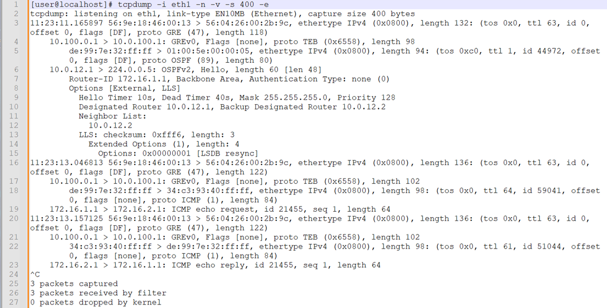
R2/PE1에서 미러링된 트래픽을 수신하는 eth1 인터페이스에서 캡처하는 것으로 시작합니다. 캡처를 시작한 후 CE 라우터 간에 단일 IPv4 ping을 수행합니다.
참고:캡처 후 텍스트 기반 tcpdump 출력을 줄 번호를 표시하는 텍스트 애플리케이션에 붙여넣었습니다. 이렇게 하면 캡처의 주요 부분을 더 쉽게 호출할 수 있습니다. 또한 가시성을 개선하기 위해 줄 바꿈을 사용하도록 설정했습니다.
캡처에서 주의해야 할 영역은 다음과 같습니다.
-
eth1 인터페이스에서 tcpdump를 호출하고 이름 확인을 방지하고, 세부 정보를 제공하고, 최대 400바이트를 캡처하고, 레이어 2 헤더를 포함하는 플래그를 포함합니다.
-
라인 3은 첫 번째 레이어 2 프레임 및 IP 패킷의 시작입니다. 이더넷 프레임은 R3/P1 라우터가 로컬로 연결된 분석기 디바이스로 트래픽을 전송하는 데 사용하는 캡슐화입니다. 대상 MAC 주소는 분석기 1의 eth1 인터페이스가 소유합니다. 100.0.100.1 IP-MAC 주소 확인은 ARP를 통해 수행됩니다. 이더넷 프레임은 IP 프로토콜을 전달함을 나타냅니다. IP 레이어에서 패킷에 Don't Fragment 비트가 설정된 것을 확인하고 페이로드가 GRE임을 식별합니다.
-
라인 4는 외부 IP 패킷 및 GRE 페이로드의 디코딩을 보여줍니다. 소스 및 대상 IP 주소는 R2/PE1의 fti0.1 인터페이스에서 구성된 GRE 터널을 반영합니다. GRE 헤더는 투명 이더넷 브리징(TEB) 프로토콜 ID를 통해 페이로드가 레이어 2 프레임임을 식별합니다. 이는 패밀리
any필터가 있는 PTX 플랫폼의 원격 포트 미러링이 레이어 2 프레임의 미러링을 초래한다는 것을 확인합니다. -
라인 5는 GRE 패킷의 페이로드에 대한 디코드입니다. 소스 및 대상 MAC 주소(각각 de:99:7e:32:ff:ff 및 01:00:5e:00:00:05)는 링크 레이어에서 최단 경로 우선(OSPF) hello 멀티캐스트에 사용되는 주소를 반영합니다. 라인 5는 또한 GRE 캡슐화된 레이어 2 프레임의 페이로드가 IP이고 IP 패킷의 페이로드가 OSPF임을 보여줍니다.
참고:CE와 PE 간의 최단 경로 우선(OSPF) hello 교환은 레이어 3 VPN에서 로컬로 이루어집니다. 수신 시 포트 미러 작업이 모든 트래픽을 캡처했기 때문에 로컬 CE에서 보낸 최단 경로 우선(OSPF) 패킷을 볼 수 있습니다. 원격 CE에서 생성된 OSPF Hello 패킷은 코어를 통해 전송되지 않으므로 캡처에서 송신으로 표시되지 않습니다.
-
라인 6은 CE1 라우터가 보낸 OSPF Hello를 디코딩합니다. 소스 IP 주소는 CE1의 et-0/0/0.0 인터페이스에 할당됩니다. 대상 IP 주소는 OSPF 멀티캐스트에 사용됩니다.
-
OSPF 디코딩을 건너뛰고 16번째 줄에 착륙합니다. 이것은 캡처의 두 번째 프레임이며 IPv4 ICMP 에코 요청을 반영합니다. 다시 한 번 레이어 2 프레임은 P1/R3 및 분석기 1 디바이스의 MAC 주소를 반영합니다. 외부 프레임이 GRE 페이로드가 포함된 IP 패킷을 전달하고 있음을 알 수 있습니다. 외부 IP 패킷의 소스 및 대상 IP 주소는 R2/PE2에서 구성된 GRE 터널을 반영합니다.
-
라인 18은 GRE 페이로드의 디코딩을 시작합니다. 다시 CE1 및 PE1 라우터의 MAC 주소를 볼 수 있습니다. IP 레이어에서는 패킷이 CE1 라우터의 루프백 주소에서 전송되는 것을 볼 수 있습니다. 대상 IP는 CE2의 루프백 주소입니다. 내부 IP 패킷의 페이로드는 CE1에서 CE2로 전송되는 ICMP 에코 요청입니다.
-
라인 20은 CE2가 보낸 ICMP 에코 응답을 디코딩합니다. 이는 포트 미러링이 CE1 전송 및 수신 방향 모두에서 작동하고 있음을 확인합니다.
-
다음으로, 분석기 2의 eth2 인터페이스에서 캡처하는 동안 CE 라우터 간에 단일 IPv6 핑을 생성합니다. 이는 R3/P 라우터의 포트 미러링 구성과 IPv6 포트 미러링 지원을 확인합니다.
참고:캡처 후 텍스트 기반 tcpdump 출력을 줄 번호를 표시하는 텍스트 애플리케이션에 붙여넣었습니다. 이렇게 하면 캡처의 주요 부분을 더 쉽게 호출할 수 있습니다. 또한 가시성을 개선하기 위해 줄 바꿈을 사용하도록 설정했습니다.
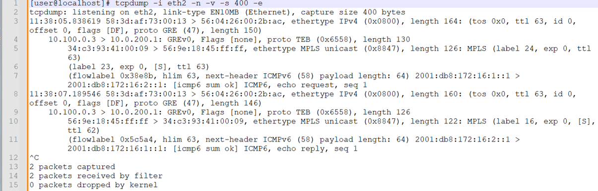
요청 및 응답 트래픽이 모두 표시됩니다. 이 포트 미러링이 P-라우터에서 발생한다는 점을 감안할 때, CE 라우터 간의 최단 경로 우선(OSPF) 패킷은 프로바이더 코어를 통해 전송되지 않으므로 미러링되지 않습니다. 이 캡처에서 주목해야 할 사항은 다음과 같습니다.
-
라인 3에서 외부 이더넷 프레임이 디코딩됩니다. 이제 소스 및 대상 MAC 주소가 각각 R4/PE2 및 분석기 디바이스를 반영합니다.
-
라인 4에서 내부 IP 패킷이 디코딩됩니다. 프레임은 GRE 캡슐화를 나타내며, 소스 및 대상 IP는 이 트래픽이 R3/P1 라우터에서 구성된 fti0.1 GRE 터널을 통해 미러링되었음을 확인합니다. GRE 캡슐화는 TEB 프로토콜을 나타내며, 이는 레이어 2 이더넷 프레임이 캡슐화되었음을 나타냅니다.
-
라인 5는 내부 이더넷 프레임과 해당 MPLS 페이로드의 디코딩을 시작합니다. 소스 MAC 주소는 R2/PE1 라우터의 et-0/0/1 인터페이스에 할당됩니다. 대상 MAC는 R3/P1 라우터의 et-0/0/0 인터페이스와 연결됩니다.
내부 이더넷 프레임은 MPLS의 페이로드를 식별합니다. 이는 MPLS 레이블과 일치하는 필터 용어를 사용하여 P 라우터에서 수행되는 레이어 2 포트 미러링과 일치합니다.
CE1에서 CE2 방향으로 미러링된 트래픽은 두 개의 MPLS 레이블을 표시합니다. RSVP 전송 레이블은 24(LSP 재신호로 인해 변경될 수 있음)이고, 내부 VRF 레이블은 R2/PE1 라우터의 CE1 라우팅 인스턴스와 연결된 VRF 레이블인 23으로 설정됩니다.
참고:이 캡처 당시 PE1이 PE2에 도달하는 데 사용하는 MPLS 전송 레이블이 변경되었습니다. 이 섹션의 캡처에 대한 현재 RSVP 전송 레이블 값 24를 반영하기 위해 R3/P1의 필터 정의를 업데이트했습니다.
-
라인 7은 MPLS 프레임의 IPv6 페이로드를 디코딩합니다. 이것은 CE1에서 CE2로 보내는 IPv6 패킷입니다. IPv6 패킷은 페이로드를 ICMP6으로 식별하고 이것이 에코 요청임을 보여줍니다.
-
라인 8은 CE2의 응답 트래픽 디코딩을 시작합니다. CE2에서 CE1 방향으로는 미러 트래픽에 단일 레이블만 존재합니다. 이것은 R3/PE1 라우터가 트래픽을 R2/PE1 라우터로 전송하기 전에 PHP(Penultimate Hop Popping)를 수행한 후 유지되는 VRF 레이블입니다. 트래픽은 P1에서 PE2 방향으로 송신될 때 미러링되었습니다.
두 분석기 디바이스에서 모두 캡처를 통해 원격 포트 미러링이 예상대로 작동하고 있음을 확인할 수 있습니다.
-
-
분석기 2 디바이스에서 캡처한 것과 동일한 CE-CE 테스트 트래픽의 GUI 디코딩으로 마무리합니다. 다시 한 번 주목해야 할 것은 MPLS 기반 PE 라우터에서 포트 미러 작업을 반영하는 MPLS 레이블의 존재입니다.
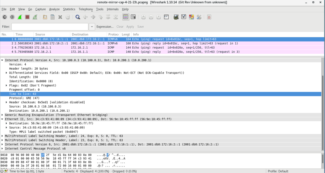 캡처는 미러링되는 IPv4 및 IPv6 테스트 트래픽을 모두 보여줍니다. 이 캡처는 P 라우터에 의해 미러링된 트래픽을 반영합니다. 결과적으로 MPLS 캡슐화가 존재합니다.
부록: 모든 라우터에서 명령 설정
이 예제를 빠르게 구성하려면 다음 명령을 복사하여 텍스트 파일에 붙여 넣고 줄 바꿈을 제거한 다음 네트워크 구성과 일치하는 데 필요한 세부 정보를 변경한 다음 명령을 복사하여 [edit] 계층 수준의 CLI에 붙여넣습니다.
R1(CE1)
del interfaces et-0/0/0
set interfaces et-0/0/0 unit 0 family inet address 10.0.12.1/24
set interfaces et-0/0/0 unit 0 family inet6 address 2001:db8:10:0:12::1/64
set interfaces lo0 unit 0 family inet address 172.16.1.1/32
set interfaces lo0 unit 0 family inet6 address 2001:db8:172:16:1::1/128
set routing-options router-id 172.16.1.1
set protocols ospf area 0.0.0.0 interface all
set protocols ospf area 0.0.0.0 interface fxp0.0 disable
set protocols ospf3 area 0.0.0.0 interface all
set protocols ospf3 area 0.0.0.0 interface fxp0.0 disable
R2(PE1) DUT1
set interfaces et-0/0/0 unit 0 filter input ce1-ce2
set interfaces et-0/0/0 unit 0 filter output ce2-ce1
set interfaces et-0/0/0 unit 0 family inet address 10.0.12.2/24
set interfaces et-0/0/0 unit 0 family inet6 address 2001:db8:10:0:12::2/64
set interfaces et-0/0/1 unit 0 family inet address 10.0.23.1/24
set interfaces et-0/0/1 unit 0 family inet6 address 2001:db8:10:0:23::1/64
set interfaces et-0/0/1 unit 0 family mpls
set interfaces fti0 unit 1 description "GRE tunnel for remote port mirror"
set interfaces fti0 unit 1 tunnel encapsulation gre source address 10.100.0.1
set interfaces fti0 unit 1 tunnel encapsulation gre destination address 10.0.100.1
set interfaces fti0 unit 1 family ccc
set interfaces lo0 unit 0 family inet address 192.168.0.2/32
set interfaces lo0 unit 0 family inet6 address 2001:db8:192:168:0::2/128
set forwarding-options port-mirroring instance pe-mirror input rate 1
set forwarding-options port-mirroring instance pe-mirror input run-length 1
set forwarding-options port-mirroring instance pe-mirror family any output interface fti0.1
set policy-options policy-statement ospf-export term 1 from protocol bgp
set policy-options policy-statement ospf-export term 1 then accept
set firewall family any filter ce1-ce2 term mirror-ce1-ce2 then count ce1-ce2-mirror
set firewall family any filter ce1-ce2 term mirror-ce1-ce2 then port-mirror-instance pe-mirror
set firewall family any filter ce1-ce2 term mirror-ce1-ce2 then accept
set firewall family any filter ce2-ce1 term mirror-ce2-ce1 then count ce2-ce1-mirror
set firewall family any filter ce2-ce1 term mirror-ce2-ce1 then port-mirror-instance pe-mirror
set firewall family any filter ce2-ce1 term mirror-ce2-ce1 then accept
set routing-instances ce1 instance-type vrf
set routing-instances ce1 protocols ospf area 0.0.0.0 interface all
set routing-instances ce1 protocols ospf export ospf-export
set routing-instances ce1 protocols ospf3 area 0.0.0.0 interface all
set routing-instances ce1 protocols ospf3 export ospf-export
set routing-instances ce1 interface et-0/0/0.0
set routing-instances ce1 route-distinguisher 65001:1
set routing-instances ce1 vrf-target target:65001:100
set routing-instances ce1 vrf-table-label
set routing-options router-id 192.168.0.2
set routing-options autonomous-system 65001
set protocols bgp group ibgp type internal
set protocols bgp group ibgp local-address 192.168.0.2
set protocols bgp group ibgp family inet unicast
set protocols bgp group ibgp family inet-vpn unicast
set protocols bgp group ibgp family inet6-vpn unicast
set protocols bgp group ibgp neighbor 192.168.0.4
set protocols mpls label-switched-path pe2 to 192.168.0.4
set protocols mpls label-switched-path pe2 no-cspf
set protocols mpls interface all
set protocols mpls interface fxp0.0 disable
set protocols ospf area 0.0.0.0 interface all
set protocols ospf area 0.0.0.0 interface fxp0.0 disable
set protocols ospf3 area 0.0.0.0 interface all
set protocols ospf3 area 0.0.0.0 interface fxp0.0 disable
set protocols ospf3 area 0.0.0.0 interface et-0/0/2.0 passive
set protocols rsvp interface all
set protocols rsvp interface fxp0 disable
R3(P 라우터) DUT 2
set interfaces et-0/0/0 description "R3-R2 P-PE"
set interfaces et-0/0/0 unit 0 filter input ce1-ce2
set interfaces et-0/0/0 unit 0 filter output ce2-ce1
set interfaces et-0/0/0 unit 0 family inet address 10.0.23.2/24
set interfaces et-0/0/0 unit 0 family inet6 address 2001:db8:10:0:23::2/64
set interfaces et-0/0/0 unit 0 family mpls
set interfaces et-0/0/1 unit 0 family inet address 10.0.34.1/24
set interfaces et-0/0/1 unit 0 family inet6 address 2001:db8:10:0:34::1/64
set interfaces et-0/0/1 unit 0 family mpls
set interfaces et-0/0/2 unit 0 family inet address 10.0.100.2/24
set interfaces fti0 unit 1 tunnel encapsulation gre source address 10.100.0.3
set interfaces fti0 unit 1 tunnel encapsulation gre destination address 10.0.200.1
set interfaces fti0 unit 1 family ccc
set interfaces lo0 unit 0 family inet address 192.168.0.3/32
set interfaces lo0 unit 0 family inet6 address 2001:db8:192:168:0::3/128
set forwarding-options port-mirroring instance p-router-mirror input rate 1
set forwarding-options port-mirroring instance p-router-mirror input run-length 0
set forwarding-options port-mirroring instance p-router-mirror family any output interface fti0.1
set firewall family any filter ce1-ce2 term ce1-ce2-mirror from mpls-label 22
set firewall family any filter ce1-ce2 term ce1-ce2-mirror then count ce1-ce2-traffic
set firewall family any filter ce1-ce2 term ce1-ce2-mirror then port-mirror-instance p-router-mirror
set firewall family any filter ce1-ce2 term else then accept
set firewall family any filter ce2-ce1 term ce2-ce1-mirror from mpls-label 16
set firewall family any filter ce2-ce1 term ce2-ce1-mirror then count ce2-ce1-traffic
set firewall family any filter ce2-ce1 term ce2-ce1-mirror then port-mirror-instance p-router-mirror
set firewall family any filter ce2-ce1 term else then accept
set routing-options router-id 192.168.0.3
set protocols mpls interface all
set protocols mpls interface fxp0.0 disable
set protocols mpls interface et-0/0/2.0 disable
set protocols ospf area 0.0.0.0 interface all
set protocols ospf area 0.0.0.0 interface fxp0.0 disable
set protocols ospf area 0.0.0.0 interface et-0/0/2.0 passive
set protocols ospf3 area 0.0.0.0 interface all
set protocols ospf3 area 0.0.0.0 interface fxp0.0 disable
set protocols ospf3 area 0.0.0.0 interface et-0/0/2.0 passive
set protocols rsvp interface all
set protocols rsvp interface fxp0 disable
R4(PE2)
set interfaces et-0/0/0 unit 0 family inet address 10.0.34.2/24
set interfaces et-0/0/0 unit 0 family inet6 address 2001:db8:10:0:34::2/64
set interfaces et-0/0/0 unit 0 family mpls
set interfaces et-0/0/1 unit 0 family inet address 10.0.45.1/24
set interfaces et-0/0/1 unit 0 family inet6 address 2001:db8:10:0:45::1/64
set interfaces et-0/0/2 unit 0 family inet address 10.0.200.2/24
set interfaces lo0 unit 0 family inet address 192.168.0.4/32
set interfaces lo0 unit 0 family inet6 address 2001:db8:192:168:0::4/128
set policy-options policy-statement ospf-export term 1 from protocol bgp
set policy-options policy-statement ospf-export term 1 then accept
set routing-instances ce2 instance-type vrf
set routing-instances ce2 protocols ospf area 0.0.0.0 interface all
set routing-instances ce2 protocols ospf export ospf-export
set routing-instances ce2 protocols ospf3 area 0.0.0.0 interface all
set routing-instances ce2 protocols ospf3 export ospf-export
set routing-instances ce2 interface et-0/0/1.0
set routing-instances ce2 route-distinguisher 65001:2
set routing-instances ce2 vrf-target target:65001:100
set routing-options router-id 192.168.0.4
set routing-options autonomous-system 65001
set protocols bgp group ibgp type internal
set protocols bgp group ibgp local-address 192.168.0.4
set protocols bgp group ibgp family inet unicast
set protocols bgp group ibgp family inet-vpn unicast
set protocols bgp group ibgp family inet6-vpn unicast
set protocols bgp group ibgp neighbor 192.168.0.2
set protocols mpls label-switched-path pe1 to 192.168.0.2
set protocols mpls label-switched-path pe1 no-cspf
set protocols mpls ipv6-tunneling
set protocols mpls interface all
set protocols mpls interface fxp0.0 disable
set protocols ospf area 0.0.0.0 interface all
set protocols ospf area 0.0.0.0 interface fxp0.0 disable
set protocols ospf area 0.0.0.0 interface et-0/0/2.0 passive
set protocols ospf3 area 0.0.0.0 interface all
set protocols ospf3 area 0.0.0.0 interface fxp0.0 disable
set protocols ospf3 area 0.0.0.0 interface et-0/0/2.0 passive
set protocols rsvp interface all
R5(CE2)
set interfaces et-0/0/0 unit 0 family inet address 10.0.45.2/24
set interfaces et-0/0/0 unit 0 family inet6 address 2001:db8:10:0:45::2/64
set interfaces lo0 unit 0 family inet address 172.16.2.1/32
set interfaces lo0 unit 0 family inet6 address 2001:db8:172:16:2::1/128
set routing-options router-id 172.16.2.1
set protocols ospf area 0.0.0.0 interface all
set protocols ospf area 0.0.0.0 interface fxp0.0 disable
set protocols ospf3 area 0.0.0.0 interface all
set protocols ospf3 area 0.0.0.0 interface fxp0.0 disable
주의 사항 및 제한 사항
이 섹션에서는 PTX 플랫폼의 원격 포트 미러링에 대한 주의 사항과 제한 사항을 나열합니다.
-
포트 미러링 인스턴스 구성의 출력 부분을 변경해야 하는 경우, 새 구성을 추가하기 전에 기존 출력 구성을 먼저 삭제하고 변경 사항을 커밋해야 합니다.
-
총 15개의 미러링 인스턴스가 지원됩니다. 원격 포트 미러 인스턴스 수가 15개를 초과하면 커밋 오류가 발생하지 않습니다.
-
주어진 미러링된 패킷은 단 하나의 원격 분석기로만 전송될 수 있습니다.
-
최대 패킷 길이는 128바이트의 배수로 구성할 수 있습니다. 내보낸 패킷은 구성된 값보다 22바이트 적습니다.
-
주어진 미러링 인스턴스에서 다중 출력 인터페이스가 지원되지 않습니다. 여러 출력 인터페이스가 구성된 경우 커밋 오류가 없습니다.
-
샘플링 프로세스는 GRES가 지원되지 않습니다. GRES 이벤트가 발생하거나 프로세스가 다시 시작되면 미러링된 트래픽이 감소합니다.
mirrord -
로컬 라우터에서 종료되는 터널 트래픽은 송신 방향으로 미러링할 수 없습니다.
-
송신 방향에서 폴리서 동작을 유발하는 필터와 함께 포트 미러링을 사용할 수 없습니다.
-
미러링된 패킷과 관련된 통계는 방화벽 카운터 또는 FTI 인터페이스 통계를 통해 확인해야 합니다.