예: 폐기 인터페이스로 패킷 전달
이 예는 폐기 라우팅을 사용하여 DoS(서비스 거부) 공격을 완화하고, 외부 공격으로부터 중요한 네트워크 리소스를 보호하고, 각 고객이 자체 보호를 시작할 수 있도록 고객에게 보호 서비스를 제공하고, DoS 시도를 기록 및 추적하는 방법을 보여줍니다.
요구 사항
이 예를 구성하기 전에 디바이스 초기화를 제외한 특별한 구성은 필요하지 않습니다.
개요
폐기 라우팅에서 라우터는 짧은 기간 동안 수백만 개의 요청이 동일한 주소로 전송되는 것을 허용하지 않는 규칙으로 구성됩니다. 단기간에 너무 많은 요청이 수신되면 라우터는 요청을 전달하지 않고 폐기합니다. 요청은 패킷을 전달하지 않는 라우터로 전송됩니다. 문제가 있는 경로는 폐기 경로 또는 블랙홀 경로라고도 합니다. 버려야 하는 경로 유형은 피어 또는 다른 고객의 고객에 대한 공격, 피어 또는 다른 고객에 대한 고객의 공격, 공격 명령을 제공하는 호스트인 공격 컨트롤러, bogon 또는 잘못된 IP 주소라고 하는 할당되지 않은 주소 공간으로 식별됩니다.
공격 시도가 식별되면 운영자는 공격을 완화하기 위한 구성을 적용할 수 있습니다. Junos OS에서 폐기 라우팅을 구성하는 한 가지 방법은 폐기 경로에 사용되는 각 다음 홉에 대해 폐기 정적 경로를 생성하는 것입니다. 폐기 정적 경로는 옵션을 discard 사용합니다.
몇 가지 예를 들면 다음과 같습니다.
user@host# show routing-options
static {
    route 192.0.2.101/32 discard;
    route 192.0.2.103/32 discard;
    route 192.0.2.105/32 discard;
}
user@host> show route protocol static terse
inet.0: 3 destinations, 3 routes (3 active, 0 holddown, 0 hidden)
+ = Active Route, - = Last Active, * = Both

A V Destination        P Prf   Metric 1   Metric 2  Next hop        AS path
* ? 192.0.2.101/32     S   5                        Discard
* ? 192.0.2.103/32     S   5                        Discard
* ? 192.0.2.105/32     S   5                        Discard
이 예에서 가장 중점을 두는 또 다른 전략은 라우팅 정책과 폐기 인터페이스를 사용하는 것입니다. 이 접근 방식에서 폐기 인터페이스에는 null 경로 경로에 할당하는 다음 홉이 포함됩니다. 폐기 인터페이스는 하나의 논리 단위(유닛 0)만 가질 수 있지만 유닛 0에서 여러 IP 주소를 구성할 수 있습니다.
몇 가지 예를 들면 다음과 같습니다.
user@host# show interfaces dsc
unit 0 {
    family inet {
        address 192.0.2.102/32 {
            destination 192.0.2.101;
        }
        address 192.0.2.104/32 {
            destination 192.0.2.103;
        }
        address 192.0.2.106/32 {
            destination 192.0.2.105;
        }
    }
}
user@host> show interfaces terse dsc
b
Interface               Admin Link Proto    Local                 Remote
dsc                     up    up
dsc.0                   up    up   inet     192.0.2.102         --> 192.0.2.101
                                            192.0.2.104         --> 192.0.2.103
                                            192.0.2.106         --> 192.0.2.105
정적 경로 폐기를 사용하는 대신 폐기 인터페이스를 사용하면 폐기 인터페이스를 통해 트래픽 카운트, 로깅 및 샘플링을 위한 필터를 구성하고 인터페이스에 할당할 수 있다는 장점이 있습니다. 이 예제에서는 이를 보여 줍니다.
실제로 패킷을 폐기하려면 BGP 세션에 연결된 라우팅 정책이 필요합니다. 폐기 대상 경로를 찾으려면 경로 필터, 액세스 목록 또는 BGP 커뮤니티 값을 사용할 수 있습니다.
예를 들어 경로 필터를 사용하는 방법은 다음과 같습니다.
경로 필터
protocols {
    bgp {
        import blackhole-by-route;
    }
}
policy-options {
    policy-statement blackhole-by-route {
        term specific-routes {
            from {
                route-filter 10.10.10.1/32 exact;
                route-filter 10.20.20.2/32 exact;
                route-filter 10.30.30.3/32 exact;
                route-filter 10.40.40.4/32 exact;
            }
            then {
                next-hop 192.0.2.101
            }
        }
    }
}
그림 1은 샘플 네트워크를 표시합니다.
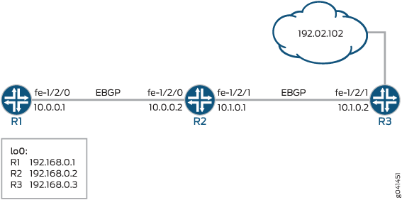
이 예에는 외부 BGP(EBGP) 세션이 설정된 라우터 3개가 포함되어 있습니다.
디바이스 R1은 공격 디바이스를 나타냅니다. 디바이스 R3은 공격을 받고 있는 디바이스에 가장 가까운 라우터를 나타냅니다. 디바이스 R2는 패킷을 폐기 인터페이스로 전달하여 공격을 완화합니다.
이 예에서는 폐기 인터페이스에 적용된 아웃바운드 필터를 보여 줍니다.
단일 null 경로 필터 사용과 관련된 문제는 가시성입니다. 모든 폐기 패킷은 동일한 카운터를 증가시킵니다. 삭제되는 패킷 범주를 보려면 DCU(대상 클래스 사용)를 사용하고 사용자 정의 클래스를 각 null 경로 커뮤니티와 연결합니다. 그런 다음 방화벽 필터에서 DCU 클래스를 참조합니다. 관련 예는 및 예: 대상 클래스를 기반으로 속도 제한 필터 구성을 참조하십시오예: 소스 및 대상 접두사를 포워딩 클래스로 그룹화.
경로 필터 및 액세스 목록을 사용하는 것과 비교할 때 커뮤니티 값을 사용하는 것이 관리상 가장 어렵고 확장성이 가장 뛰어난 접근 방식입니다. 따라서 이 예에 표시된 접근 방식입니다.
기본적으로 다음 홉은 외부 BGP(EBGP) 피어 주소와 같아야 합니다. null 경로 서비스에 대한 다음 홉을 변경하려면 EBGP 세션에서 다중 홉 기능을 구성해야 합니다.
CLI 빠른 구성은(는) 그림 1 내 모든 디바이스의 구성을 보여줍니다.
섹션 #configuration756__policy-discard-st은 디바이스 R2의 단계를 설명합니다.
구성
절차
CLI 빠른 구성
이 예를 빠르게 구성하려면, 아래 명령을 복사하여 텍스트 파일로 붙여 넣은 다음 모든 라인브레이크를 제거하고, 네트워크 구성을 일치하는 데 필요한 세부 사항을 바꾸고 [edit] 계층 수준에서 명령을 CLI로 복사해 붙여 넣습니다.
디바이스 R1
set interfaces fe-1/2/0 unit 0 family inet address 10.0.0.1/30
set interfaces lo0 unit 0 family inet address 192.168.0.1/32
set protocols bgp group ext type external
set protocols bgp group ext peer-as 200
set protocols bgp group ext neighbor 10.0.0.2
set routing-options autonomous-system 100
디바이스 R2
set interfaces fe-1/2/0 unit 0 family inet address 10.0.0.2/30
set interfaces fe-1/2/1 unit 0 family inet address 10.1.0.1/30
set interfaces dsc unit 0 family inet filter output log-discard
set interfaces dsc unit 0 family inet address 192.0.2.102/32 destination 192.0.2.101
set interfaces lo0 unit 0 family inet address 192.168.0.2/32
set protocols bgp import blackhole-policy
set protocols bgp group ext type external
set protocols bgp group ext multihop
set protocols bgp group ext export dsc-export
set protocols bgp group ext neighbor 10.0.0.1 peer-as 100
set protocols bgp group ext neighbor 10.1.0.2 peer-as 300
set policy-options policy-statement blackhole-policy term blackhole-communities from community blackhole-all-routers
set policy-options policy-statement blackhole-policy term blackhole-communities then next-hop 192.0.2.101
set policy-options policy-statement dsc-export from route-filter 192.0.2.101/32 exact
set policy-options policy-statement dsc-export from route-filter 192.0.2.102/32 exact
set policy-options policy-statement dsc-export then community set blackhole-all-routers
set policy-options policy-statement dsc-export then accept
set policy-options community blackhole-all-routers members 100:5555
set routing-options static route 192.0.2.102/32 next-hop 192.0.2.101
set routing-options autonomous-system 200
set firewall filter log-discard term one then count counter
set firewall filter log-discard term one then log
디바이스 R3
set interfaces fe-1/2/1 unit 0 family inet address 10.1.0.2/30
set interfaces lo0 unit 0 family inet address 192.168.0.3/32
set interfaces lo0 unit 0 family inet address 192.0.2.102/32
set protocols bgp group ext type external
set protocols bgp group ext peer-as 200
set protocols bgp group ext neighbor 10.1.0.1
set routing-options autonomous-system 300
단계별 절차
다음 예는 구성 계층에서 다양한 수준의 탐색이 필요합니다. 이를 수행하는 방법에 대한 지침은 Junos OS CLI 사용자 가이드를 참조하십시오구성 모드에서 CLI 편집기 사용.
디바이스 R2 구성:
라우터 인터페이스를 생성합니다.
[edit interfaces]
user@R2# set fe-1/2/0 unit 0 family inet address 10.0.0.2/30
user@R2# set fe-1/2/1 unit 0 family inet address 10.1.0.1/30
user@R2# set lo0 unit 0 family inet address 192.168.0.2/32
모든 패킷을 일치시키고 패킷을 카운트하고 기록하는 방화벽 필터를 구성합니다.
[edit firewall filter log-discard term one]
user@R2# set then count counter
user@R2# set then log
폐기 인터페이스를 생성하고 출력 방화벽 필터를 적용합니다.
입력 방화벽 필터는 이 컨텍스트에 영향을 주지 않습니다.
[edit interfaces dsc unit 0 family inet]
user@R2# set filter output log-discard
user@R2# set address 192.0.2.102/32 destination 192.0.2.101
폐기 인터페이스에 지정된 대상 주소로 다음 홉을 전송하는 정적 경로를 구성합니다.
[edit routing-options static]
user@R2# set route 192.0.2.102/32 next-hop 192.0.2.101
BGP 피어링을 구성합니다.
[edit protocols bgp ]
user@R2# set group ext type external
user@R2# set group ext multihop
user@R2# set group ext neighbor 10.0.0.1 peer-as 100
user@R2# set group ext neighbor 10.1.0.2 peer-as 300
라우팅 정책을 구성합니다.
[edit policy-options policy-statement blackhole-policy term blackhole-communities]
user@R2# set from community blackhole-all-routers
user@R2# set then next-hop 192.0.2.101
[edit policy-options policy-statement dsc-export]
user@R2# set from route-filter 192.0.2.101/32 exact
user@R2# set from route-filter 192.0.2.102/32 exact
user@R2# set then community set blackhole-all-routers
user@R2# set then accept
[edit policy-options community blackhole-all-routers]
user@R2# set members 100:5555
라우팅 정책을 적용합니다.
[edit protocols bgp ]
user@R2# set import blackhole-policy
user@R2# set group ext export dsc-export
AS(Autonomous System) 번호를 구성합니다.
[edit routing-options]
user@R2# set autonomous-system 200
결과
구성 모드에서 , show protocols , show policy-options, show routing-options및 show firewall 명령을 실행하여 show interfaces구성을 확인합니다. 출력 결과가 의도한 구성대로 표시되지 않으면 이 예의 지침을 반복하여 구성을 수정하십시오.
[edit]
user@R2# show interfaces
fe-1/2/0 {
    unit 0 {
        family inet {
            address 10.0.0.2/30;
        }
    }
}
fe-1/2/1 {
    unit 0 {
        family inet {
            address 10.1.0.1/30;
        }
    }
}
dsc {
    unit 0 {
        family inet {
            filter {
                output log-discard;
            }
            address 192.0.2.102/32 {
                destination 192.0.2.101;
            }
        }
    }
}
lo0 {
    unit 0 {
        family inet {
            address 192.168.0.2/32;
        }
    }
}
user@R2# show protocols
bgp {
    import blackhole-policy;
    group ext {
        type external;
        multihop;
        export dsc-export;
        neighbor 10.0.0.1 {
            peer-as 100;
        }
        neighbor 10.1.0.2 {
            peer-as 300;
        }
    }
}
user@R2# show policy-options
policy-statement blackhole-policy {
    term blackhole-communities {
        from community blackhole-all-routers;
        then {
            next-hop 192.0.2.101;
        }
    }
}
policy-statement dsc-export {
    from {
        route-filter 192.0.2.101/32 exact;
        route-filter 192.0.2.102/32 exact;
    }
    then {
        community set blackhole-all-routers;
        accept;
    }
}
community blackhole-all-routers members 100:5555;
user@R2# show routing-options
static {
    route 192.0.2.102/32 next-hop 192.0.2.101;
}
autonomous-system 200;
user@R2# show firewall
filter log-discard {
    term one {
        then {
            count counter;
            log;
        }
    }
}
디바이스 구성을 마쳤으면 구성 모드에서 commit을(를) 입력합니다.
검증
구성이 올바르게 작동하고 있는지 확인합니다.
방화벽 카운터 지우기
목적
카운터를 지워 알려진 영(0) 상태에서 시작하는지 확인합니다.
작업
디바이스 R2에서 명령을 실행합니다
clear firewall.user@R2> clear firewall filter log-discard
디바이스 R2에서 명령을 실행합니다
show firewall.user@R2> show firewall filter log-discard Filter: /log-discard Counters: Name Bytes Packets counter 0 0
192.0.2.101 주소 ping
목적
대상 주소로 패킷을 보냅니다.
작업
디바이스 R1에서 명령을 실행합니다 ping .
user@R1> ping 192.0.2.101
PING 192.0.2.101 (192.0.2.101): 56 data bytes
^C
--- 192.0.2.101 ping statistics ---
4 packets transmitted, 0 packets received, 100% packet loss
의미
예상대로 ping 요청이 실패하고 응답이 전송되지 않습니다. 패킷이 삭제됩니다.
출력 필터 확인
목적
디바이스 R2의 방화벽 필터가 제대로 작동하고 있는지 확인합니다.
작업
디바이스 R2에서 명령을 입력합니다 show firewall filter log-discard .
user@R2> show firewall filter log-discard
Filter: log-discard
Counters:
Name                                                Bytes              Packets
counter                                               336                    4
의미
예상대로 카운터가 증가하고 있습니다.
ping 패킷은 추가로 20바이트의 IP 오버헤드와 8바이트의 ICMP 헤더를 전달합니다.
커뮤니티 속성 확인
목적
경로가 community 속성으로 태그되고 있는지 확인합니다.
작업
디바이스 R1에서 디바이스 R2의 show route extensive 인접 주소 192.0.2.101을 사용하여 명령을 입력합니다.
user@R1> show route 192.0.2.101 extensive

inet.0: 4 destinations, 4 routes (4 active, 0 holddown, 0 hidden)
192.0.2.101/32 (1 entry, 1 announced)
TSI:
KRT in-kernel 192.0.2.101/32 -> {10.0.0.2}
        *BGP    Preference: 170/-101
                Next hop type: Router, Next hop index: 684
                Address: 0x94141d8
                Next-hop reference count: 2
                Source: 10.0.0.2
                Next hop: 10.0.0.2 via fe-1/2/0.0, selected
                Session Id: 0x8000a
                State: <Active Ext>
                Local AS:   100 Peer AS:   200
                Age: 53:03
                Validation State: unverified
                Task: BGP_200.10.0.0.2+63097
                Announcement bits (1): 2-KRT
                AS path: 200 I
                Communities: 100:5555
                Accepted
                Localpref: 100
                Router ID: 192.168.0.2
의미
예상대로 디바이스 R2가 디바이스 R1에 192.0.2.101 경로를 보급하면 디바이스 R2는 100:5555 커뮤니티 태그를 추가합니다.