
다음 홉 기반 동적 터널
예: 다음 홉 기반 MPLS-over-UDP 동적 터널 구성
이 예는 터널 복합 다음 홉을 포함하는 동적 MPLS-over-UDP 터널 구성하는 방법을 보여줍니다. MPLS-over-UDP 기능은 디바이스에서 지원되는 IP 터널 수에 대한 확장 이점을 제공합니다.
Junos OS 릴리스 18.3R1부터는 PTX 시리즈 라우터와 QFX 시리즈 스위치에서 MPLS-over-UDP 터널이 지원됩니다. PTX 라우터 또는 QFX 스위치에 구성된 모든 동적 터널에 대해 터널 대상 경로를 해결하기 위해 터널 복합 다음 홉, 간접 다음 홉 및 포워딩 다음 홉이 생성됩니다. 또한 정책 제어를 사용하여 계층 수준에서 [edit routing-options dynamic-tunnels] forwarding-rib 구성 문을 포함하여 선택한 접두사에 대한 동적 터널을 해결할 수 있습니다.
요구 사항
이 예에서 사용되는 하드웨어 및 소프트웨어 구성 요소는 다음과 같습니다.
-
MPC 및 MIC가 있는 5개의 MX 시리즈 라우터.
-
프로바이더 에지(PE) 라우터에서 실행되는 Junos OS 릴리스 16.2 이상.
시작하기 전에:
-
루프백 인터페이스를 포함하여 디바이스 인터페이스를 구성합니다.
-
디바이스의 라우터 ID 및 자동 시스템 번호를 구성합니다.
-
원격 PE 디바이스와 내부 BGP(IBGP) 세션을 설정합니다.
-
디바이스 간에 OSPF 피어링을 설정합니다.
개요
Junos OS 릴리스 16.2부터 동적 UDP 터널은 구성된 모든 터널에 대해 터널 복합 다음 터널 생성을 지원합니다. 이러한 다음 홉 기반 동적 UDP 터널을 MPLS-over-UDP 터널이라고 합니다. 터널 복합 다음 홉은 기본적으로 MPLS-over-UDP 터널에 대해 활성화됩니다.
MPLS-over-UDP 터널은 본질적으로 양방향 또는 단방향일 수 있습니다.
-
양방향 - PE 디바이스가 양방향으로 MPLS-over-UDP 터널을 통해 연결된 경우, 이를 양방향 MPLS-over-UDP 터널이라고 합니다.
-
단방향 - 두 개의 PE 디바이스가 한 방향으로 MPLS-over-UDP 터널을 통해 연결되고 다른 방향으로 MPLS/IGP를 통해 연결되는 경우, 이를 단방향 MPLS-over-UDP 터널이라고 합니다.
단방향 MPLS-over-UDP 터널은 마이그레이션 시나리오 또는 두 개의 PE 디바이스가 두 개의 분리된 네트워크를 통해 서로 연결을 제공하는 경우에 사용됩니다. 단방향 MPLS-over-UDP 터널에는 역방향 터널이 존재하지 않기 때문에 트래픽을 포워딩하기 위해 원격 PE 디바이스에서 필터 기반 MPLS-over-UDP 캡슐화 해제를 구성해야 합니다.
Junos OS 릴리스 18.2R1부터 단방향 MPLS-over-UDP 터널이 있는 PTX 시리즈 라우터 및 QFX10000에서는 MPLS-over-UDP 패킷에 대한 입력 필터와 역방향 터널 방향으로 패킷을 전달하기 위한 IP 및 UDP 헤더의 캡슐화 해제 작업을 사용하여 원격 PE 디바이스를 구성해야 합니다.
예를 들어, 원격 PE 디바이스인 디바이스 PE2에서 단방향 MPLS-over-UDP 터널에 대해 다음 구성이 필요합니다.
PE2
[edit firewall filter]
user@host# set Decap_Filter term udp_decap from protocol udp
user@host# set Decap_Filter term udp_decap from destination-port 6635
user@host# set Decap_Filter term udp_decap then count UDP_PKTS
user@host# set Decap_Filter term udp_decap then decapsulate mpls-in-udp
user@host# set Decap_Filter term def then count def_pkt
user@host# set Decap_Filter term def then accept
위의 샘플 구성 Decap_Filter 에서는 MPLS-over-UDP 캡슐화 해제에 사용되는 방화벽 필터의 이름이 있습니다. 이 용어 udp_decap 는 디바이스 PE2의 코어 대면 인터페이스에서 UDP 패킷을 수락한 다음 포워딩을 위해 MPLS-over-UDP 패킷을 MPLS-over-IP 패킷으로 캡슐화 해제하기 위한 입력 필터입니다.
필터 기반 MPLS-over-UDP 캡슐화 해제를 보는 등 show firewall filter 기존 방화벽 운영 모드 명령을 사용할 수 있습니다.
예를 들면 다음과 같습니다.
user@host >show firewall filter Decap_Filter
Filter: Decap_Filter
Counters:
Name                                                Bytes              Packets
UDP_PKTS                                            16744                  149
def_pkt                                             13049                  136
단방향 MPLS-over-UDP 터널의 경우:
-
IPv4 주소만 외부 헤더로 지원됩니다. 필터 기반 MPLS-over-UDP 캡슐화 해제는 외부 헤더에서 IPv6 주소를 지원하지 않습니다.
-
캡슐화 해제 후에는 기본 라우팅 인스턴스만 지원됩니다.
Junos OS 릴리스 17.1부터 MPC 및 MIC가 있는 MX 시리즈 라우터에서 MPLS-over-UDP 터널의 확장 제한이 증가합니다.
Junos 릴리스 19.2R1부터 MPC와 MIC가 있는 MX 시리즈 라우터에서 CSC(carrier supporting carrier) 아키텍처는 지원 통신사의 PE 디바이스 간에 설정된 동적 IPv4 UDP 터널을 통해 MPLS 트래픽을 전송하는 MPLS-over-UDP 터널과 함께 구축될 수 있습니다. 이러한 향상으로 MPLS-over-UDP 터널이 제공하는 확장 이점이 더욱 향상됩니다. IPv6 UDP 터널에는 MPLS-over-UDP 터널을 통한 CSC 지원이 지원되지 않습니다.
기존의 동적 터널 기능에는 완전한 정적 구성이 필요합니다. 현재 보급된 경로의 피어 디바이스에서 수신된 터널 정보는 무시됩니다. Junos OS 릴리스 17.4R1부터 MX 시리즈 라우터에서 다음 홉 기반 동적 MPLS-over-UDP 터널은 BGP 캡슐화 확장 커뮤니티를 사용하여 신호됩니다. BGP 내보내기 정책은 터널 유형을 지정하고, 발신자 측 터널 정보를 보급하며, 수신자 측 터널 정보를 구문 분석 및 전달하는 데 사용됩니다. 수신된 터널 커뮤니티 유형에 따라 터널이 생성됩니다.
BGP는 여러 터널 캡슐화를 지원합니다. 여러 기능을 수신하면 구성된 BGP 정책 및 터널 기본 설정을 기반으로 다음 홉 기반 동적 터널이 생성됩니다. 터널 기본 설정은 터널을 설정하기 위해 양쪽 터널 끝에서 일관되어야 합니다. 기본적으로 MPLS-over-UDP 터널이 GRE 터널보다 선호됩니다. 동적 터널 구성이 존재하는 경우, 수신된 터널 커뮤니티보다 우선합니다.
다음 홉 기반의 동적 MPLS-over-UDP 터널을 구성할 때, 다음 사항을 염두에 두어야 합니다.
-
PE 디바이스 간에 IBGP 세션을 구성해야 합니다.
-
다음 홉 기반 동적 터널 캡슐화(UDP 및 GRE) 간의 전환이 허용되며, 이는 각 모드에서 지원되는 IP 터널 확장 값과 관련하여 네트워크 성능에 영향을 미칠 수 있습니다.
-
동일한 터널 대상에 대해 GRE 및 UDP 다음 홉 기반의 동적 터널 캡슐화 유형을 모두 갖는 것은 커밋 실패로 이어집니다.
-
단방향 MPLS-over-UDP 터널의 경우, 패킷이 전달되도록 원격 PE 디바이스에서 필터 기반 MPLS-over-UDP 캡슐화 해제를 명시적으로 구성해야 합니다.
-
GRES(Graceful 라우팅 엔진 스위치오버)는 MPLS-over-UDP와 함께 지원되며, MPLS-over-UDP 터널 유형 플래그는 통합 ISSU 및 NSR을 준수합니다.
-
MPLS-over-UDP 터널은 라이트 모드의 가상 MX(vMX)에서 지원됩니다.
-
MPLS-over-UDP 터널은 새로운 IPv4-mapped-IPv6 다음 터널을 기반으로 동적 GRE 터널 생성을 지원합니다.
-
MPLS-over-UDP 터널은 Contrail과의 상호 운용성에서 지원되며, 여기서 MPLS-over-UDP 터널은 contrail vRouter에서 MX 게이트웨이로 생성됩니다. 이를 가능하게 하려면 MX 시리즈 라우터에서 contrail vRouter로의 경로에 다음 커뮤니티를 보급해야 합니다.
[edit policy-options community]
udp members 0x030c:64512:13;
특정 시점에 contrail vRouter에서는 단 하나의 터널 유형(다음 홉 기반 동적 GRE 터널, MPLS-over-UDP 터널 또는 VXLAN)만 지원됩니다.
-
다음 기능은 다음 홉 기반 동적 MPLS-over-UDP 터널 구성에서 지원되지 않습니다.
-
RSVP 자동 메시
-
일반 IPV6 GRE 및 UDP 터널 구성
-
논리적 시스템
-
토폴로지
그림 1 은 동적 MPLS-over-UDP 터널을 통한 레이어 3 VPN 시나리오를 보여줍니다. 고객 에지(CE) 디바이스 CE1 및 CE2는 각각 프로바이더 에지(PE) 디바이스 PE1 및 PE2에 연결됩니다. PE 디바이스는 공급자 디바이스(디바이스 P1)에 연결되며, 내부 BGP(IBGP) 세션은 두 개의 PE 디바이스를 상호 연결합니다. 동적 다음 홉 기반 양방향 MPL-over-UDP 터널은 PE 디바이스 간에 구성됩니다.
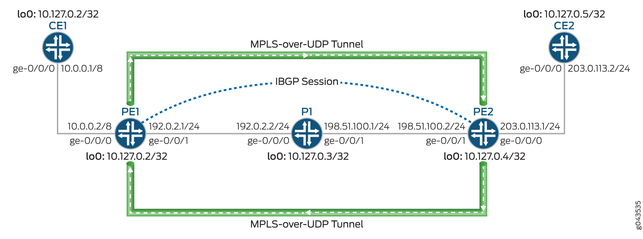
MPLS-over-UDP 터널은 다음과 같이 처리됩니다.
-
MPLS-over-UDP 터널이 구성된 후, inet.3 라우팅 테이블의 터널에 대해 터널 복합 다음 홉이 있는 터널 대상 마스크 경로가 생성됩니다. 이 IP 터널 경로는 동적 터널 구성이 삭제되는 경우에만 철회됩니다.
터널 복합 다음 홉 속성에는 다음이 포함됩니다.
-
레이어 3 VPN 복합 다음 홉이 비활성화된 경우 - 소스 및 대상 주소, 캡슐화 문자열 및 VPN 레이블.
-
레이어 3 VPN 복합 다음 홉 및 접두사별 VPN 레이블 할당이 활성화된 경우 - 소스 주소, 대상 주소 및 캡슐화 문자열.
-
레이어 3 VPN 복합 다음 홉이 활성화되고 접두사별 VPN 레이블 할당이 비활성화된 경우—소스 주소, 대상 주소 및 캡슐화 문자열. 이 경우 경로는 보조 경로와 함께 다른 가상 라우팅 및 포워딩 인스턴스 테이블에 추가됩니다.
-
-
PE 디바이스는 IBGP 세션을 사용하여 상호 연결됩니다. 원격 BGP neighbor에 대한 IBGP 경로 다음 홉은 프로토콜 다음 홉이며, 터널 다음 홉과 함께 터널 마스크 경로를 사용하여 확인됩니다.
-
프로토콜 다음 홉이 터널 복합 다음 홉을 통해 해결된 후, 포워딩 다음 홉이 있는 간접 다음 홉이 생성됩니다.
-
터널 복합 다음 홉은 간접 다음 홉의 다음 홉을 전달하는 데 사용됩니다.
구성
CLI 빠른 구성
이 예를 빠르게 구성하려면, 아래 명령을 복사하여 텍스트 파일로 붙여 넣은 다음 모든 라인브레이크를 제거하고, 네트워크 구성을 일치하는 데 필요한 세부 사항을 변경하고, 계층 수준에서 [edit] 명령을 복사하여 CLI에 붙여 넣은 다음, 구성 모드에서 들어갑니다 commit .
세1
set interfaces ge-0/0/0 unit 0 family inet address 10.0.0.1/8
set interfaces lo0 unit 0 family inet address 10.127.0.1/32
set routing-options router-id 10.127.0.1
set routing-options autonomous-system 65200
set protocols bgp group ce1-pe1 export export-loopback-direct
set protocols bgp group ce1-pe1 peer-as 100
set protocols bgp group ce1-pe1 neighbor 10.0.0.2
set policy-options policy-statement export-loopback-direct term term-1 from interface lo0.0
set policy-options policy-statement export-loopback-direct term term-1 from route-filter 10.127.0.1/32 exact
set policy-options policy-statement export-loopback-direct term term-1 then accept
세2
set interfaces ge-0/0/0 unit 0 family inet address 203.0.113.2/24
set interfaces lo0 unit 0 family inet address 10.127.0.5/32
set routing-options router-id 10.127.0.5
set routing-options autonomous-system 65200
set protocols bgp group ce1-pe1 export export-loopback-direct
set protocols bgp group ce1-pe1 peer-as 65100
set protocols bgp group ce1-pe1 neighbor 203.0.113.1
set policy-options policy-statement export-loopback-direct term term-1 from interface lo0.0
set policy-options policy-statement export-loopback-direct term term-1 from route-filter 10.127.0.5/32 exact
set policy-options policy-statement export-loopback-direct term term-1 then accept
PE1
set interfaces ge-0/0/0 unit 0 family inet address 10.0.0.2/8
set interfaces ge-0/0/1 unit 0 family inet address 192.0.2.1/24
set interfaces ge-0/0/1 unit 0 family mpls
set interfaces lo0 unit 0 family inet address 10.127.0.2/32
set routing-options static route 10.33.0/16 next-hop 192.0.2.2
set routing-options router-id 10.127.0.2
set routing-options autonomous-system 65100
set routing-options forwarding-table export pplb
set routing-options dynamic-tunnels gre next-hop-based-tunnel
set routing-options dynamic-tunnels udp-dyn-tunnel-to-pe2 source-address 10.127.0.2
set routing-options dynamic-tunnels udp-dyn-tunnel-to-pe2 udp
set routing-options dynamic-tunnels udp-dyn-tunnel-to-pe2 destination-networks 10.127.0.0/24
set protocols bgp group IBGP type internal
set protocols bgp group IBGP local-address 10.127.0.2
set protocols bgp group IBGP family inet-vpn unicast
set protocols bgp group IBGP neighbor 10.127.0.4
set protocols ospf area 0.0.0.0 interface ge-0/0/1.0
set protocols ospf area 0.0.0.0 interface lo0.0 passive
set routing-instances MPLS-over-UDP-PE1 instance-type vrf
set routing-instances MPLS-over-UDP-PE1 interface ge-0/0/0.0
set routing-instances MPLS-over-UDP-PE1 route-distinguisher 10.127.0.2:1
set routing-instances MPLS-over-UDP-PE1 vrf-target target:600:1
set routing-instances MPLS-over-UDP-PE1 protocols bgp group pe1-ce1 peer-as 65200
set routing-instances MPLS-over-UDP-PE1 protocols bgp group pe1-ce1 neighbor 10.0.0.1 as-override
P1
set interfaces ge-0/0/0 unit 0 family inet address 192.0.2.2/24
set interfaces ge-0/0/0 unit 0 family mpls
set interfaces ge-0/0/1 unit 0 family inet address 198.51.100.1/24
set interfaces ge-0/0/1 unit 0 family mpls
set interfaces lo0 unit 0 family inet address 10.127.0.3/32
set routing-options router-id 10.127.0.3
set routing-options autonomous-system 65100
set protocols ospf area 0.0.0.0 interface ge-0/0/0.0
set protocols ospf area 0.0.0.0 interface ge-0/0/1.0
set protocols ospf area 0.0.0.0 interface lo0.0 passive
PE2
set interfaces ge-0/0/0 unit 0 family inet address 203.0.113.1/24
set interfaces ge-0/0/1 unit 0 family inet address 198.51.100.2/24
set interfaces ge-0/0/1 unit 0 family mpls
set interfaces lo0 unit 0 family inet address 10.127.0.4/8
set routing-options nonstop-routing
set routing-options router-id 10.127.0.4
set routing-options autonomous-system 65100
set routing-options forwarding-table export pplb
set routing-options dynamic-tunnels udp-dyn-tunnel-to-pe1 source-address 10.127.0.4
set routing-options dynamic-tunnels udp-dyn-tunnel-to-pe1 udp
set routing-options dynamic-tunnels udp-dyn-tunnel-to-pe1 destination-networks 10.127.0.0/24
set protocols bgp group IBGP type internal
set protocols bgp group IBGP local-address 10.127.0.4
set protocols bgp group IBGP family inet-vpn unicast
set protocols bgp group IBGP neighbor 10.127.0.2
set protocols ospf area 0.0.0.0 interface ge-0/0/1.0
set protocols ospf area 0.0.0.0 interface lo0.0 passive
set routing-instances MPLS-over-UDP-PE2 instance-type vrf
set routing-instances MPLS-over-UDP-PE2 interface ge-0/0/0.0
set routing-instances MPLS-over-UDP-PE2 route-distinguisher 10.127.0.4:1
set routing-instances MPLS-over-UDP-PE2 vrf-target target:600:1
set routing-instances MPLS-over-UDP-PE2 protocols bgp group ebgp peer-as 65200
set routing-instances MPLS-over-UDP-PE2 protocols bgp group ebgp neighbor 203.0.113.2 as-override
절차
단계별 절차
다음 예에서는 구성 계층에서 다양한 수준의 탐색이 필요합니다. CLI 탐색에 대한 정보는 CLI 사용자 가이드의 구성 모드에서 CLI 편집기 사용을 참조하십시오.
디바이스 PE1 구성:
-
디바이스의 루프백 인터페이스를 포함하여 디바이스 인터페이스를 구성합니다.
[edit interfaces]
user@PE1# set ge-0/0/0 unit 0 family inet address 10.0.0.2/8
user@PE1# set ge-0/0/1 unit 0 family inet address 192.0.2.1/24
user@PE1# set ge-0/0/1 unit 0 family mpls
user@PE1# set lo0 unit 0 family inet address 10.127.0.2/8
-
디바이스 P1을 다음 홉 대상으로 사용하여 디바이스 PE1의 경로에 대한 고정 경로를 구성합니다.
[edit routing-options]
user@PE1# set static route 10.33.0.0/16 next-hop 192.0.2.2
-
디바이스 PE1의 라우터 ID 및 자율 시스템 번호를 구성합니다.
[edit routing-options]
user@PE1# set router-id 10.127.0.2
user@PE1# set autonomous-system 65100
-
일부 접두사를 통해 MPLS-over-UDP 동적 터널 경로를 해결하도록 정책 제어를 구성합니다.
[edit routing-options dynamic-tunnels]
user@PTX-PE1# set forwarding-rib inet.0 inet-import dynamic-tunnel-fwd-route-import
[edit routing-options dynamic-tunnels]
user@PTX-PE1# set forwarding-rib inet6.0 inet-import dynamic-tunnel-fwd-route-import
-
(PTX 시리즈만 해당) 을 통해 동적 터널 대상 경로를 해결하기 위한 inet-import 정책을 구성합니다.
[edit policy-options]
user@PTX-PE1# set policy-statement dynamic-tunnel-fwd-route-import term 1 from route-filter 10.127.0.4/32 exact
user@PTX-PE1# set policy-statement dynamic-tunnel-fwd-route-import term 1 then accept
user@PTX-PE1# set policy-options policy-statement dynamic-tunnel-fwd-route-import then reject
-
PE 디바이스 간에 IBGP 피어링을 구성합니다.
[edit protocols]
user@PE1# set bgp group IBGP type internal
user@PE1# set bgp group IBGP local-address 10.127.0.2
user@PE1# set bgp group IBGP family inet-vpn unicast
user@PE1# set bgp group IBGP neighbor 10.127.0.4
-
관리 인터페이스를 제외한 디바이스 PE1의 모든 인터페이스에 OSPF를 구성합니다.
[edit protocols]
user@PE1# set ospf area 0.0.0.0 interface ge-0/0/1.0
user@PE1# set ospf area 0.0.0.0 interface lo0.0 passive
-
디바이스 PE1에서 다음 홉 기반 동적 GRE 터널 구성을 활성화합니다.
참고:이 단계는 다음 홉 기반 동적 GRE 터널과 MPLS-over-UDP 터널 간의 구현 차이를 설명하기 위해서만 필요합니다.
[edit routing-options]
user@PE1# set dynamic-tunnels gre next-hop-based-tunnel
-
디바이스 PE1에서 디바이스 PE2로의 MPLS-over-UDP 터널 매개 변수를 구성합니다.
[edit routing-options]
user@PE1# set dynamic-tunnels udp-dyn-tunnel-to-pe2 source-address 10.127.0.2
user@PE1# set dynamic-tunnels udp-dyn-tunnel-to-pe2 udp
user@PE1# set dynamic-tunnels udp-dyn-tunnel-to-pe2 destination-networks 10.127.0.0/24
-
디바이스 PE1 및 기타 라우팅 인스턴스 매개 변수에 VRF 라우팅 인스턴스를 구성합니다.
[edit routing-instances]
user@PE1# set MPLS-over-UDP-PE1 instance-type vrf
user@PE1# set MPLS-over-UDP-PE1 interface ge-0/0/0.0
user@PE1# set MPLS-over-UDP-PE1 route-distinguisher 10.127.0.2:1
user@PE1# set MPLS-over-UDP-PE1 vrf-target target:600:1
-
디바이스 CE1과의 피어링을 위해 라우팅 인스턴스 구성에서 BGP를 활성화합니다.
[edit routing-instances]
user@PE1# set MPLS-over-UDP-PE1 protocols bgp group pe1-ce1 peer-as 65200
user@PE1# set MPLS-over-UDP-PE1 protocols bgp group pe1-ce1 neighbor 10.0.0.1 as-override
결과
구성 모드에서 , show routing-options, show protocols및 show routing-instances 명령을 show interfaces입력하여 구성을 확인합니다. 출력에 의도한 구성이 표시되지 않으면 이 예의 지침을 반복하여 구성을 수정합니다.
user@PE1# show interfaces
ge-0/0/0 {
    unit 0 {
        family inet {
            address 10.0.0.2/8;
        }
    }
}
ge-0/0/1 {
    unit 0 {
        family inet {
            address 192.0.2.1/24;
        }
        family mpls;
    }
}
lo0 {
    unit 0 {
        family inet {
            address 10.127.0.2/32;
        }
    }
}
user@PE1# show routing-options
static {
    route 10.33.0.0/16 next-hop 192.0.2.2;
}
router-id 10.127.0.2;
autonomous-system 65100;
forwarding-table {
    export pplb;
}
dynamic-tunnels {
    gre next-hop-based-tunnel;
    udp-dyn-tunnel-to-pe2 {
        source-address 10.127.0.2;
        udp;
        destination-networks {
            10.127.0.0/24;
        }
    }
}
user@PE1# show protocols
bgp {
    group IBGP {
        type internal;
        local-address 10.127.0.2;
        family inet-vpn {
            unicast;
        }
        neighbor 10.127.0.4;
    }
}
ospf {
    area 0.0.0.0 {
        interface ge-0/0/1.0;
        interface lo0.0 {
            passive;
        }
    }
}
user@PE1# show routing-instances
MPLS-over-UDP-PE1 {
    instance-type vrf;
    interface ge-0/0/0.0;
    route-distinguisher 10.127.0.2:1;
    vrf-target target:600:1;
    protocols {
        bgp {
            group pe1-ce1 {
                peer-as 65200;
                neighbor 10.0.0.1 {
                    as-override;
                }
            }
        }
    }
}
디바이스 구성이 완료되면 구성 모드에서 들어갑니다 commit .
검증
구성이 제대로 작동하고 있는지 확인합니다.
- PE 디바이스 간 연결 확인
- 디바이스 PE1에서 동적 터널 경로 확인
- 디바이스 PE2에서 동적 터널 경로 확인
- 경로에 예상되는 indirect-next-hop 플래그가 있는지 확인
PE 디바이스 간 연결 확인
목적
디바이스 PE1과 디바이스 PE2 간의 BGP 피어링 상태와 디바이스 PE2에서 수신된 BGP 경로를 확인합니다.
작업
운영 모드에서 and show route receive-protocol bgp ip-address table bgp.l3vpn.0 명령을 실행합니다show bgp summary.
user@PE1> show bgp summary
Groups: 2 Peers: 2 Down peers: 0
Table          Tot Paths  Act Paths Suppressed    History Damp State    Pending
bgp.l3vpn.0
                       2          2          0          0          0          0
Peer                     AS      InPkt     OutPkt    OutQ   Flaps Last Up/Dwn State|#Active/Received/Accepted/Damped...
10.127.0.4             65100        139        136       0       0       58:23 Establ
  bgp.l3vpn.0: 2/2/2/0
  MPLS-over-UDP-PE1.inet.0: 2/2/2/0
10.10.0.1               65200        135        136       0       0       58:53 Establ
  MPLS-over-UDP-PE1.inet.0: 1/1/1/0
user@PE1> show route receive-protocol bgp 10.127.0.4 table bgp.l3vpn.0
bgp.l3vpn.0: 2 destinations, 2 routes (2 active, 0 holddown, 0 hidden)
  Prefix                  Nexthop              MED     Lclpref    AS path
  10.127.0.4:1:127.0.0.5/8
*                         10.127.0.4                  65100        65200 I
의미
-
첫 번째 출력에서 BGP 세션 상태는
Establ입니다. 이는 세션이 작동 중이고 PE 디바이스가 피어링되었음을 의미합니다. -
두 번째 출력에서 디바이스 PE1은 디바이스 PE2로부터 BGP 경로를 학습했습니다.
디바이스 PE1에서 동적 터널 경로 확인
목적
inet.3 라우팅 테이블의 경로와 디바이스 PE1의 동적 터널 데이터베이스 정보를 확인합니다.
작업
운영 모드에서 , show dynamic-tunnels database terse, 및 show dynamic-tunnels database summary show dynamic-tunnels database명령을 실행합니다show route table inet.3.
user@PE1> show route table inet.3
inet.3: 2 destinations, 2 routes (2 active, 0 holddown, 0 hidden)
+ = Active Route, - = Last Active, * = Both
10.127.0.0/24     *[Tunnel/300] 00:21:18
                      Tunnel
127.0.0.4/8     *[Tunnel/300] 00:21:18
                      Tunnel Composite
user@PE1> show dynamic-tunnels database terse
Table: inet.3

Destination-network: 10.127.0.0/24
Destination         Source          Next-hop                  Type        Status
10.127.0.4/8      10.127.0.2     0xb395b10 nhid 613        udp         Up
user@PE1> show dynamic-tunnels database
Table: inet.3
. . .
Tunnel to: 10.127.0.4/32
  Reference count: 2
  Next-hop type: UDP
    Source address: 10.127.0.2 Tunnel Id: 2
    Next hop: tunnel-composite, 0xb395b10, nhid 613
      VPN Label: Push 299776 Reference count: 3
      Traffic Statistics: Packets 0, Bytes 0
      State: Up
user@PE1> show dynamic-tunnels database summary
Dynamic Tunnels,  Total 1 displayed
GRE Tunnel:
Active Tunnel Mode, Next Hop Base
  IFL Based,  Total 0 displayed, Up 0, Down 0
  Nexthop Based,  Total 0 displayed, Up 0, Down 0
RSVP Tunnel:
  Total 0 displayed
UDP Tunnel:
  Total 1 displayed, Up 1, Down 0
의미
-
첫 번째 출력에서 디바이스 PE1이 MPLS-over-UDP 터널로 구성되기 때문에 inet.3 라우팅 테이블 경로 항목에 대한 터널 복합 경로가 생성됩니다.
-
나머지 출력에서는 MPLS-over-UDP 터널가 터널 캡슐화 유형, 터널 다음 홉 매개 변수 및 터널 상태와 함께 표시됩니다.
디바이스 PE2에서 동적 터널 경로 확인
목적
inet.3 라우팅 테이블의 경로와 디바이스 PE2의 동적 터널 데이터베이스 정보를 확인합니다.
작업
운영 모드에서 및 명령을 실행 show route table inet.3합니다 show dynamic-tunnels database terse .
user@PE2> show route table inet.3
inet.3: 2 destinations, 2 routes (2 active, 0 holddown, 0 hidden)
+ = Active Route, - = Last Active, * = Both

10.127.0.0/24      *[Tunnel/300] 00:39:31
                      Tunnel
10.127.0.2/32     *[Tunnel/300] 00:24:53
                      Tunnel Composite
user@PE1> show dynamic-tunnels database terse
Table: inet.3

Destination-network: 127.0.0.0/8
Destination         Source          Next-hop                  Type        Status
10.127.0.2/32      10.127.0.4     0xb395450 nhid 615        udp         Up
의미
출력은 디바이스 PE1과 유사하게 MPLS-over-UDP 터널 생성 및 다음 홉 인터페이스로 할당된 다음 홉 ID를 보여줍니다.
경로에 예상되는 indirect-next-hop 플래그가 있는지 확인
목적
디바이스 PE1 및 디바이스 PE2가 패킷 포워딩 엔진 포워딩 테이블에서 다음 홉 바인딩 포워딩에 대한 간접 다음 홉을 유지하도록 구성되었는지 확인합니다.
작업
운영 모드의 디바이스 PE1 및 디바이스 PE2에서 명령을 실행 show krt indirect-next-hop 합니다.
user@PE1> show krt indirect-next-hop
Indirect Nexthop:
Index: 1048574 Protocol next-hop address: 10.127.0.4
  RIB Table: bgp.l3vpn.0
  Label: Push 299776
  Policy Version: 1                     References: 1
  Locks: 3                              0xb2ab630
  Flags: 0x0
  INH Session ID: 0x0
  INH Version ID: 0
  Ref RIB Table: unknown
        Tunnel type: UDP, Reference count: 3, nhid: 613
        Destination address: 10.127.0.4, Source address: 10.127.0.2
        Tunnel id: 2, VPN Label: Push 299776, TTL action: prop-ttl
      IGP FRR Interesting proto count : 1
      Chain IGP FRR Node Num          : 1
         IGP Resolver node(hex)       : 0xb3c70dc
         IGP Route handle(hex)        : 0xb1ae688      IGP rt_entry protocol        : Tunnel
         IGP Actual Route handle(hex) : 0x0            IGP Actual rt_entry protocol : Any
user@PE2> show krt indirect-next-hop
Indirect Nexthop:
Index: 1048575 Protocol next-hop address: 10.127.0.2
  RIB Table: bgp.l3vpn.0
  Label: Push 299776
  Policy Version: 1                     References: 2
  Locks: 3                              0xb2ab740
  Flags: 0x0
  INH Session ID: 0x0
  INH Version ID: 0
  Ref RIB Table: unknown
        Tunnel type: UDP, Reference count: 3, nhid: 615
        Destination address: 10.127.0.2, Source address: 10.127.0.4
        Tunnel id: 1, VPN Label: Push 299776, TTL action: prop-ttl
      IGP FRR Interesting proto count : 2
      Chain IGP FRR Node Num          : 1
         IGP Resolver node(hex)       : 0xb3d3a28
         IGP Route handle(hex)        : 0xb1ae634      IGP rt_entry protocol        : Tunnel
         IGP Actual Route handle(hex) : 0x0            IGP Actual rt_entry protocol : Any
의미
출력은 PE 디바이스 사이에 다음 홉 기반의 동적 MPLS-over-UDP 터널이 생성됨을 보여줍니다.
문제 해결
다음 홉 기반 동적 터널 문제를 해결하려면 다음을 참조하십시오.
문제 해결 명령어
문제
다음 홉 기반의 동적 MPLS-over-UDP 터널 구성이 적용되지 않습니다.
해결책
다음 홉 기반 MPLS-over-UDP 터널 구성의 문제를 해결하려면 문 계층에서 [edit routing-options dynamic-tunnels] 다음 traceroute 명령을 사용합니다.
-
traceoptions file file-name -
traceoptions file size file-size -
traceoptions flag all
예를 들면 다음과 같습니다.
[edit routing-options dynamic-tunnels]
traceoptions {
    file udp_dyn_pe1.wri size 4294967295;
    flag all;
}
다음 홉 기반 동적 터널에 대한 스푸핑 방지 보호 개요
데이터센터에 대규모 IP 터널을 구축하는 것이 증가함에 따라 사용자가 손상된 가상 머신(VM)의 악성 트래픽을 제한할 수 있는 보안 조치를 추가할 필요가 있습니다. 한 가지 가능한 공격은 게이트웨이 라우터를 통해 손상된 서버에서 임의의 고객 VPN에 트래픽을 삽입하는 것입니다. 이러한 경우 IP 터널에 대한 스푸핑 방지 검사는 합법적인 소스만 지정된 IP 터널에서 데이터 센터로 트래픽을 주입하는지 확인합니다.
다음 홉 기반 동적 IP 터널은 디바이스에서 생성된 모든 동적 터널에 대해 터널 복합 다음 터널을 생성합니다. 다음 홉 기반 동적 터널은 구성된 모든 새로운 동적 터널에 대해 물리적 인터페이스에 대한 종속성을 제거하므로 다음 홉 기반 동적 터널을 구성하면 디바이스에서 생성할 수 있는 동적 터널 수에 비해 확장성 이점이 제공됩니다. Junos OS 릴리스 17.1부터는 다음 홉 기반 동적 터널에 대한 다음 홉 기반 동적 IP 터널에 대한 스푸핑 방지 기능이 제공됩니다. 이러한 개선을 통해 게이트웨이 라우터를 통해 손상된 서버에서 임의의 고객 VPN에 트래픽이 삽입되는 것을 방지하기 위한 보안 조치가 구현됩니다.
스푸핑 방지는 패킷 포워딩 엔진에서 역방향 경로 전달 검사를 사용하여 구현됩니다. 터널을 통해 라우팅 인스턴스로 들어오는 트래픽에 대해 검사가 수행됩니다. 현재 게이트웨이 라우터가 터널에서 트래픽을 수신하면 대상 조회만 완료되고 그에 따라 패킷이 전달됩니다. 스푸핑 방지 기능이 활성화되면 게이트웨이 라우터는 터널 대상 조회 외에도 VPN에서 캡슐화 패킷 IP 헤더의 소스 주소 조회도 수행합니다. 이렇게 하면 합법적인 소스가 지정된 IP 터널을 통해 트래픽을 주입할 수 있습니다. 결과적으로, 스푸핑 방지 보호는 지정된 터널의 합법적인 소스에서 터널 트래픽이 수신되도록 보장합니다.
그림 2 는 스푸핑 방지 보호에 대한 요구 사항이 포함된 샘플 토폴로지를 보여줍니다.
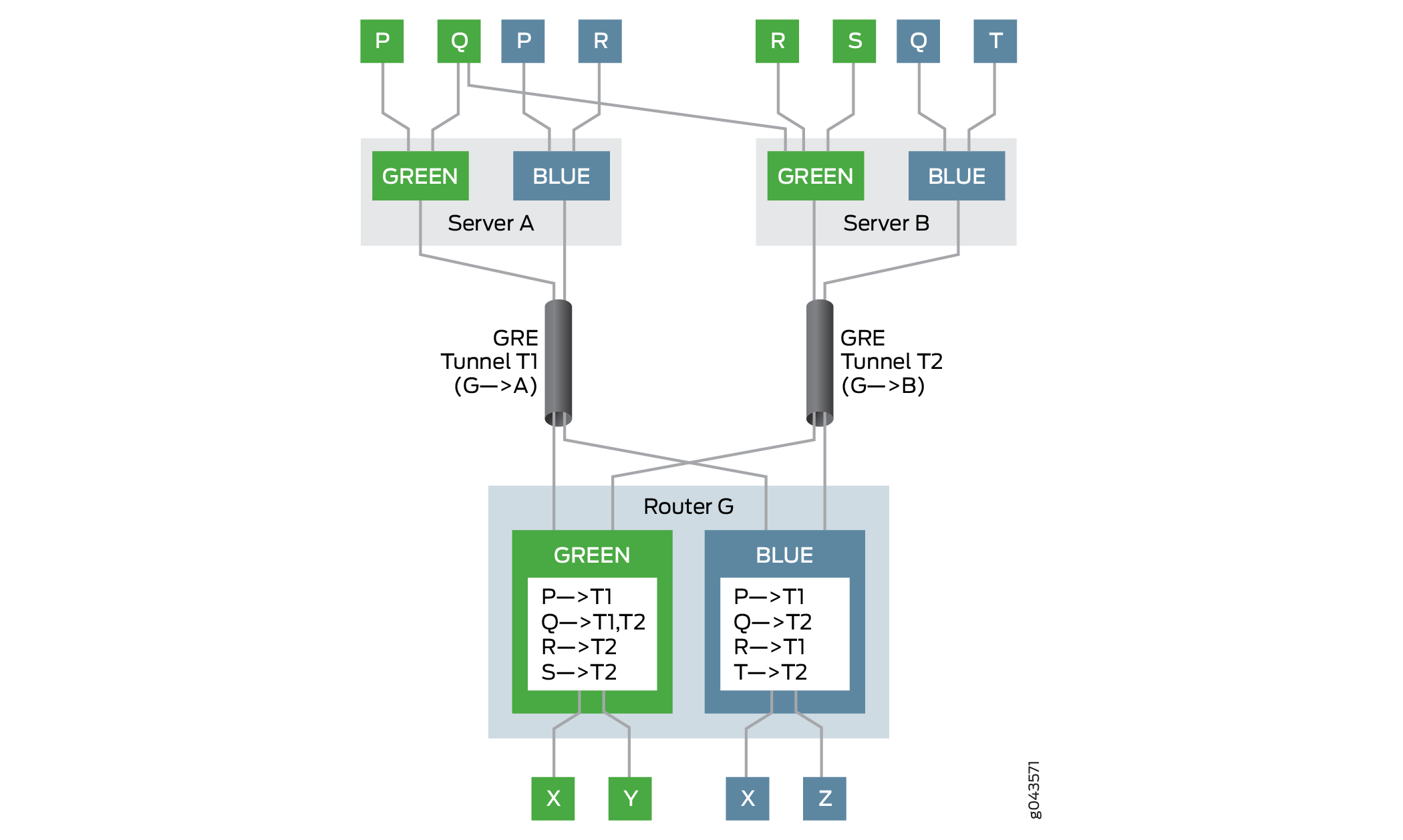 에 대한 스푸핑 방지 보호
이 예에서 게이트웨이 라우터는 라우터 G입니다. 라우터 G에는 녹색과 파란색의 두 개의 VPN이 있습니다. 서버 A와 서버 B의 두 서버는 각각 다음 홉 기반 동적 터널 T1과 T2를 통해 라우터 G의 녹색 및 파란색 VPN에 도달할 수 있습니다. 서버에 연결된 여러 호스트 및 가상 머신(P, Q, R, S 및 T)은 게이트웨이 라우터인 라우터 G를 통해 VPN에 연결할 수 있습니다. 라우터 G에는 녹색 및 파란색 VPN에 대한 가상 라우팅 및 포워딩(VRF) 테이블이 있으며, 각 테이블은 해당 VPN의 가상 머신에 대한 연결성 정보로 채워져 있습니다.
예를 들어, VPN 그린에서 라우터 G는 터널 T1을 사용하여 호스트 P에 도달하고, 터널 T2를 사용하여 호스트 R과 S에 도달하며, 터널 T1과 T2 사이에서 로드 밸런싱을 수행하여 멀티호밍 호스트 Q에 도달합니다. VPN Blue에서 라우터 G는 터널 T1을 사용하여 호스트 P 및 R에 도달하고 터널 T2를 사용하여 호스트 Q 및 T에 도달합니다.
다음과 같은 경우 역방향 경로 포워딩에 대해 검사를 통과합니다.
-
패킷이 지정된 터널의 합법적인 소스에서 전송됩니다.
VPN Green의 호스트 P는 터널 T1을 사용하여 호스트 X에 패킷을 보냅니다. 라우터 G는 터널 T1을 통해 호스트 P에 도달할 수 있기 때문에 패킷이 호스트 X에 전달되고 전달될 수 있습니다.
-
지정된 터널의 멀티호밍 소스에서 패킷이 전송됩니다.
VPN Green의 호스트 Q는 서버 A와 B에서 멀티호밍되며 터널 T1과 T2를 통해 라우터 G에 도달할 수 있습니다. 호스트 Q는 터널 T1을 사용하여 호스트 Y에 패킷을 보내고 터널 T2를 사용하여 호스트 X에 패킷을 보냅니다. 라우터 G는 터널 T1과 T2를 통해 호스트 Q에 도달할 수 있기 때문에 패킷이 각각 호스트 Y와 X로 전달되도록 허용합니다.
레이어 3 VPN은 기본적으로 스푸핑 방지 기능이 활성화되어 있지 않습니다. 다음 홉 기반 동적 터널에 대한 스푸핑 방지를 활성화하려면 계층 수준에서 [edit routing-instances routing-instance-name routing-options forwarding-table] 문을 포함 ip-tunnel-rpf-check 합니다. 역방향 경로 전달 검사는 VRF 라우팅 인스턴스에만 적용됩니다. 기본 모드는 로 설정strict되며, 여기서 지정되지 않은 터널의 소스에서 오는 패킷이 검사를 통과하지 못합니다. 모드는 ip-tunnel-rpf-check 다음과 같이 설정할 수 있습니다. loose여기서 패킷이 존재하지 않는 소스에서 오면 역방향 경로 전달 확인이 실패합니다. 역방향 경로 포워딩 확인에 실패한 패킷을 카운트하고 기록하도록 문 아래에 ip-tunnel-rpf-check 선택적 방화벽 필터를 구성할 수 있습니다.
다음 샘플 출력은 스푸핑 방지 구성을 보여줍니다.
[edit routing-instances routing-instance-name routing-options forwarding-table]
ip-tunnel-rpf-check {
    mode loose;
    fail-filter filter-name;
}
다음 홉 기반 동적 터널에 대한 스푸핑 방지 보호를 구성할 때 다음 지침을 고려하십시오.
-
스푸핑 방지 보호는 IPv4 터널 및 IPv4 데이터 트래픽에 대해서만 사용할 수 있습니다. 스푸핑 방지 기능은 IPv6 터널 및 IPv6 데이터 트래픽에서 지원되지 않습니다.
-
다음 홉 기반 동적 터널에 대한 스푸핑 방지는 손상된 가상 머신(내부 소스 역방향 경로 전달 확인)을 감지하고 방지할 수 있지만 레이블 스푸핑인 손상된 서버는 차단할 수 없습니다.
-
다음 홉 기반 IP 터널은 inet.0 라우팅 테이블에서 시작되고 종료될 수 있습니다.
-
스푸핑 방지 보호는 VRF 라우팅 인스턴스에 레이블 스위칭 인터페이스(LSI)(사용
vrf-table-label) 또는 가상 터널(VT) 인터페이스가 있을 때 효과적입니다. VRF 라우팅 인스턴스의 레이블을 사용하면per-next-hop스푸핑 방지 보호가 지원되지 않습니다. -
내부
rpf fail-filterIP 패킷에만 적용됩니다. -
스푸핑 방지 검사를 활성화해도 디바이스의 다음 홉 기반 동적 터널의 확장 제한에는 영향을 미치지 않습니다.
-
VRF 라우팅 인스턴스에 대해 스푸핑 방지 보호가 활성화된 시스템 리소스 활용률은 스푸핑 방지 보호가 활성화되지 않은 다음 홉 기반 동적 터널의 활용률보다 약간 높습니다.
-
스푸핑 방지 보호는 네트워크 성능에 미치는 영향을 최소화하는 추가적인 소스 IP 주소 확인이 필요합니다.
-
GRES(Graceful 라우팅 엔진 스위치오버) 및 ISSU(In-Service Software Upgrade)는 스푸핑 방지 보호와 함께 지원됩니다.
예: 다음 홉 기반 동적 터널에 대한 스푸핑 방지 보호 구성
이 예는 가상 라우팅 및 포워딩(VRF) 라우팅 인스턴스에 대한 역방향 경로 전달 검사를 구성하여 다음 홉 기반 동적 터널에 대한 스푸핑 방지 보호를 활성화하는 방법을 보여줍니다. 이 검사를 통해 합법적인 소스가 지정된 IP 터널을 통해 트래픽을 주입하고 있는지 확인합니다.
요구 사항
이 예에서 사용되는 하드웨어 및 소프트웨어 구성 요소는 다음과 같습니다.
-
각각 호스트 디바이스에 연결된 MIC가 있는 3개의 MX 시리즈 라우터.
-
하나 또는 모든 라우터에서 실행되는 Junos OS 릴리스 17.1 이상
시작하기 전에:
-
Flexible PIC Concentrator에서 터널 서비스 구성을 활성화합니다.
-
라우터 인터페이스를 구성합니다.
-
라우터 ID를 구성하고 라우터에 대한 자율 시스템 번호를 할당합니다.
-
터널 엔드포인트와 내부 BGP(IBGP) 세션을 설정합니다.
-
모든 라우터에서 RSVP를 구성합니다.
-
모든 라우터에서 OSPF 또는 기타 내부 게이트웨이 프로토콜을 구성합니다.
-
두 라우터 간에 두 개의 동적 다음 홉 기반 IP 터널을 구성합니다.
-
모든 라우터-호스트 연결에 대해 VRF 라우팅 인스턴스를 구성합니다.
개요
Junos OS 릴리스 17.1부터 스푸핑 방지 기능이 다음 홉 기반 동적 IP 터널에 추가되었으며, 여기서 터널를 통해 라우팅 인스턴스로 들어오는 트래픽에 대한 검사가 패킷 포워딩 엔진에서 역방향 경로 포워딩을 사용합니다.
현재 게이트웨이 라우터가 터널에서 트래픽을 수신하면 포워딩 전에 대상 주소 조회만 수행됩니다. 스푸핑 방지 기능을 통해 게이트웨이 라우터는 VPN에서 캡슐화 패킷 IP 헤더의 소스 주소를 조회하여 합법적인 소스가 지정된 IP 터널을 통해 트래픽을 주입하고 있는지 확인합니다. 이를 엄격 모드라고 하며 스푸핑 방지 보호의 기본 동작입니다. 지정되지 않은 터널에서 트래픽을 전달하기 위해 손실 모드에서 역방향 경로 전달 확인이 활성화됩니다. 존재하지 않는 소스에서 수신된 트래픽의 경우, 엄격한 모드와 느슨한 모드 모두에서 역방향 경로 전달 확인이 실패합니다.
스푸핑 방지는 VRF 라우팅 인스턴스에서 지원됩니다. 동적 터널에 대한 스푸핑 방지를 활성화하려면 계층 수준에서 [edit routing-instances routing-instance-name routing-options forwarding-table] 문을 포함 ip-tunnel-rpf-check 합니다.
토폴로지
그림 3 은 스푸핑 방지 기능이 활성화된 샘플 네트워크 토폴로지를 보여줍니다. 라우터 R0, R1 및 R2는 각각 호스트 Host0, Host1 및 Host2에 각각 연결되어 있습니다. 두 개의 GRE(Generic Routing Encapsulation) 다음 홉 기반 동적 터널, 터널 1 및 터널 2 – 라우터 R0을 각각 라우터 R1 및 R2와 연결합니다. VRF 라우팅 인스턴스는 각 라우터와 연결된 호스트 디바이스 간에 실행됩니다.
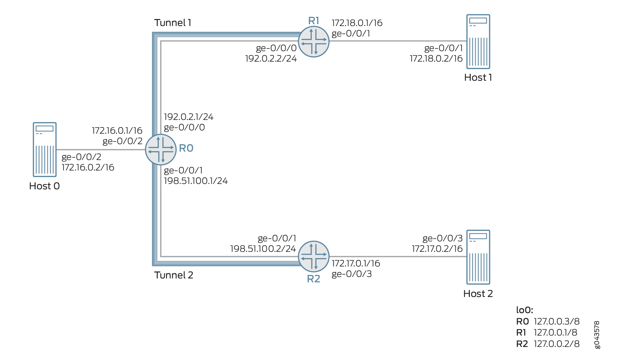 에 대한 스푸핑 방지 보호
예를 들어, 라우터 R2에서 다음 홉 기반의 동적 GRE 터널(터널 2)를 통해 라우터 0에서 패킷 3개(패킷 A, B, C)가 수신됩니다. 이러한 패킷의 소스 IP 주소는 172.17.0.2(패킷 A), 172.18.0.2(패킷 B) 및 172.20.0.2(패킷 C)입니다.
패킷 A와 B의 소스 IP 주소는 각각 호스트 2와 호스트 1에 속합니다. 패킷 C는 존재하지 않는 소스 터널입니다. 이 예에서 지정된 터널은 터널 2이고, 지정되지 않은 터널은 터널 1입니다. 따라서 패킷은 다음과 같이 처리됩니다.
-
Packet A—소스가 지정된 터널(터널 2)에서 오기 때문에 패킷 A는 역방향 경로 포워딩 검사를 통과하고 터널 2를 통해 포워딩되도록 처리됩니다.
-
Packet B—소스가 지정되지 않은 터널인 터널 1에서 오기 때문에 기본적으로 패킷 B는 엄격 모드에서 역방향 경로 전달 검사에 실패합니다. 느슨한 모드가 활성화되면 패킷 B를 포워딩할 수 있습니다.
-
Packet C—소스가 존재하지 않는 터널 소스이기 때문에 패킷 C가 역방향 경로 포워딩 확인에 실패하고 패킷이 전달되지 않습니다.
구성
CLI 빠른 구성
이 예를 빠르게 구성하려면, 아래 명령을 복사하여 텍스트 파일로 붙여 넣은 다음 모든 라인브레이크를 제거하고, 네트워크 구성을 일치하는 데 필요한 세부 사항을 변경하고, 계층 수준에서 [edit] 명령을 복사하여 CLI에 붙여 넣은 다음, 구성 모드에서 들어갑니다 commit .
라우터 R0
set interfaces ge-0/0/0 unit 0 family inet address 192.0.2.1/24
set interfaces ge-0/0/1 unit 0 family inet address 198.51.100.1/24
set interfaces ge-0/0/2 vlan-tagging
set interfaces ge-0/0/2 unit 0 vlan-id 1
set interfaces ge-0/0/2 unit 0 family inet address 172.16.0.1/16
set interfaces lo0 unit 0 family inet address 10.1.1.1/32
set routing-options router-id 10.1.1.1
set routing-options autonomous-system 100
set routing-options dynamic-tunnels gre next-hop-based-tunnel
set routing-options dynamic-tunnels T1 source-address 192.0.2.1
set routing-options dynamic-tunnels T1 gre
set routing-options dynamic-tunnels T1 destination-networks 192.0.2.0/24
set routing-options dynamic-tunnels T2 source-address 198.51.100.1
set routing-options dynamic-tunnels T2 gre
set routing-options dynamic-tunnels T2 destination-networks 198.51.100.0/24
set protocols rsvp interface all
set protocols rsvp interface fxp0.0 disable
set protocols bgp group IBGP type internal
set protocols bgp group IBGP local-address 10.1.1.1
set protocols bgp group IBGP family inet-vpn unicast
set protocols bgp group IBGP neighbor 20.1.1.1
set protocols bgp group IBGP neighbor 30.1.1.1
set protocols ospf traffic-engineering
set protocols ospf area 0.0.0.0 interface lo0.0 passive
set protocols ospf area 0.0.0.0 interface all
set routing-instances VPN1 instance-type vrf
set routing-instances VPN1 interface ge-0/0/2.0
set routing-instances VPN1 route-distinguisher 100:100
set routing-instances VPN1 vrf-target target:100:1
set routing-instances VPN1 vrf-table-label
set routing-instances VPN1 routing-options forwarding-table ip-tunnel-rpf-check mode strict
set routing-instances VPN1 protocols bgp group External type external
set routing-instances VPN1 protocols bgp group External family inet unicast
set routing-instances VPN1 protocols bgp group External peer-as 200
set routing-instances VPN1 protocols bgp group External neighbor 172.16.0.1
라우터 R1
set interfaces ge-0/0/0 unit 0 family inet address 192.0.2.2/24
set interfaces ge-0/0/1 vlan-tagging
set interfaces ge-0/0/1 unit 0 vlan-id 2
set interfaces ge-0/0/1 unit 0 family inet address 172.18.0.1/16
set interfaces lo0 unit 0 family inet address 20.1.1.1/32
set routing-options router-id 20.1.1.1
set routing-options autonomous-system 100
set routing-options dynamic-tunnels gre next-hop-based-tunnel
set routing-options dynamic-tunnels T1 source-address 192.0.2.2
set routing-options dynamic-tunnels T1 gre
set routing-options dynamic-tunnels T1 destination-networks 192.0.2.0/24
set protocols rsvp interface all
set protocols rsvp interface fxp0.0 disable
set protocols bgp group IBGP type internal
set protocols bgp group IBGP local-address 20.1.1.1
set protocols bgp group IBGP family inet-vpn unicast
set protocols bgp group IBGP neighbor 30.1.1.1
set protocols bgp group IBGP neighbor 10.1.1.1
set protocols ospf traffic-engineering
set protocols ospf area 0.0.0.0 interface lo0.0 passive
set protocols ospf area 0.0.0.0 interface all
set routing-instances VPN2 instance-type vrf
set routing-instances VPN2 interface ge-0/0/1.0
set routing-instances VPN2 route-distinguisher 100:200
set routing-instances VPN2 vrf-target target:200:1
set routing-instances VPN2 vrf-table-label
R2
set interfaces ge-0/0/1 unit 0 family inet address 198.51.100.2/24
set interfaces ge-0/0/2 vlan-tagging
set interfaces ge-0/0/2 unit 0 vlan-id 3
set interfaces ge-0/0/2 unit 0 family inet address 172.17.0.1/16
set interfaces lo0 unit 0 family inet address 30.1.1.1/32
set routing-options router-id 30.1.1.1
set routing-options autonomous-system 100
set routing-options dynamic-tunnels gre next-hop-based-tunnel
set routing-options dynamic-tunnels T2 source-address 198.51.100.2
set routing-options dynamic-tunnels T2 gre
set routing-options dynamic-tunnels T2 destination-networks 198.51.100.0/24
set protocols rsvp interface all
set protocols rsvp interface fxp0.0 disable
set protocols bgp group IBGP type internal
set protocols bgp group IBGP local-address 30.1.1.1
set protocols bgp group IBGP family inet-vpn unicast
set protocols bgp group IBGP neighbor 20.1.1.1
set protocols bgp group IBGP neighbor 10.1.1.1
set protocols ospf traffic-engineering
set protocols ospf area 0.0.0.0 interface lo0.0 passive
set protocols ospf area 0.0.0.0 interface all
set routing-instances VPN3 instance-type vrf
set routing-instances VPN3 interface ge-0/0/2.0
set routing-instances VPN3 route-distinguisher 100:300
set routing-instances VPN3 vrf-target target:300:1
set routing-instances VPN3 vrf-table-label
절차
단계별 절차
다음 예에서는 구성 계층에서 다양한 수준의 탐색이 필요합니다. CLI 탐색에 대한 정보는 CLI 사용자 가이드의 구성 모드에서 CLI 편집기 사용을 참조하십시오.
라우터 R0을 구성하려면 다음을 수행합니다.
-
루프백 인터페이스를 포함하여 라우터 R0의 인터페이스를 구성합니다.
[edit interfaces]
user@R0# set ge-0/0/0 unit 0 family inet address 192.0.2.1/24
user@R0# set ge-0/0/1 unit 0 family inet address 198.51.100.1/24
user@R0# set ge-0/0/2 vlan-tagging
user@R0# set ge-0/0/2 unit 0 vlan-id 1
user@R0# set ge-0/0/2 unit 0 family inet address 172.16.0.1/16
user@R0# set lo0 unit 0 family inet address 10.1.1.1/32
-
라우터 R0에 대한 라우터 ID 및 자율 시스템 번호를 할당합니다.
[edit routing-options]
user@R0# set router-id 10.1.1.1
user@R0# set autonomous-system 100
-
라우터 간에 IBGP 피어링을 구성합니다.
[edit protocols]
user@R0# set bgp group IBGP type internal
user@R0# set bgp group IBGP local-address 10.1.1.1
user@R0# set bgp group IBGP family inet-vpn unicast
user@R0# set bgp group IBGP neighbor 20.1.1.1
user@R0# set bgp group IBGP neighbor 30.1.1.1
-
관리 인터페이스를 제외한 라우터 R0의 모든 인터페이스에 최단 경로 우선(OSPF)을 구성합니다.
[edit protocols]
user@R0# set ospf traffic-engineering
user@R0# set ospf area 0.0.0.0 interface lo0.0 passive
user@R0# set ospf area 0.0.0.0 interface all
-
관리 인터페이스를 제외한 라우터 R0의 모든 인터페이스에 RSVP를 구성합니다.
[edit protocols]
user@R0# set rsvp interface all
user@R0# set rsvp interface fxp0.0 disable
-
라우터 R0에서 다음 홉 기반 동적 GRE 터널 구성을 활성화합니다.
[edit routing-options]
user@R0# set dynamic-tunnels gre next-hop-based-tunnel
-
라우터 R0에서 라우터 R1까지의 동적 GRE 터널 매개 변수를 구성합니다.
[edit routing-options]
user@R0# set dynamic-tunnels T1 source-address 192.0.2.1
user@R0# set dynamic-tunnels T1 gre
user@R0# set dynamic-tunnels T1 destination-networks 192.0.2.0/24
-
라우터 R0에서 라우터 R2로의 동적 GRE 터널 매개 변수를 구성합니다.
[edit routing-options]
user@R0# set dynamic-tunnels T2 source-address 198.51.100.1
user@R0# set dynamic-tunnels T2 gre
user@R0# set dynamic-tunnels T2 destination-networks 198.51.100.0/24
-
라우터 R0에 가상 라우팅 및 포워딩(VRF) 라우팅 인스턴스를 구성하고 호스트 1에 연결된 인터페이스를 VRF 인스턴스에 할당합니다.
[edit routing-instances]
user@R0# set VPN1 instance-type vrf
user@R0# set VPN1 route-distinguisher 100:100
user@R0# set VPN1 vrf-target target:100:1
user@R0# set VPN1 vrf-table-label
user@R0# set VPN1 interface ge-0/0/2.0
-
VRF 라우팅 인스턴스에 대해 호스트 1과 외부 BGP 세션을 구성합니다.
[edit routing-instances]
user@R0# set VPN1 protocols bgp group External type external
user@R0# set VPN1 protocols bgp group External family inet unicast
user@R0# set VPN1 protocols bgp group External peer-as 200
user@R0# set VPN1 protocols bgp group External neighbor 172.16.0.1
-
라우터 R0에서 VRF 라우팅 인스턴스에 대한 스푸핑 방지 보호를 구성합니다. 이렇게 하면 라우터 0에서 다음 홉 기반 동적 터널인 T1 및 T2에 대한 역방향 경로 전달 확인이 가능합니다.
[edit routing-instances]
user@R0# set VPN1 routing-options forwarding-table ip-tunnel-rpf-check mode strict
결과
구성 모드에서 , show routing-options, show protocols및 show routing-options 명령을 show interfaces입력하여 구성을 확인합니다. 출력에 의도한 구성이 표시되지 않으면 이 예의 지침을 반복하여 구성을 수정합니다.
user@R0# show interfaces
ge-0/0/0 {
    unit 0 {
        family inet {
            address 192.0.2.1/24;
        }
    }
}
ge-0/0/1 {
    unit 0 {
        family inet {
            address 198.51.100.1/24;
        }
    }
}
ge-0/0/2 {
    vlan-tagging;
    unit 0 {
        vlan-id 1;
        family inet {
            address 172.16.0.1/16;
        }
    }
}
lo0 {
    unit 0 {
        family inet {
            address 10.1.1.1/32;
        }
    }
}
user@R0# show routing-options
router-id 10.1.1.1;
autonomous-system 100;
dynamic-tunnels {
    gre next-hop-based-tunnel;
    T1 {
        source-address 192.0.2.1;
        gre;
        destination-networks {
            192.0.2.0/24;
        }
    }
    T2 {
        source-address 198.51.100.1;
        gre;
        destination-networks {
            198.51.100.0/24;
        }
    }
}
user@R0# show protocols
rsvp {
    interface all;
    interface fxp0.0 {
        disable;
    }
}
bgp {
    group IBGP {
        type internal;
        local-address 10.1.1.1;
        family inet-vpn {
            unicast;
        }
        neighbor 20.1.1.1;
        neighbor 30.1.1.1;
    }
}
ospf {
    traffic-engineering;
    area 0.0.0.0 {
        interface lo0.0 {
            passive;
        }
        interface all;
    }
}
user@R0# show routing-instances
VPN1 {
    instance-type vrf;
    interface ge-0/0/2.0;
    route-distinguisher 100:100;
    vrf-target target:100:1;
    vrf-table-label;
    routing-options {
        forwarding-table {
            ip-tunnel-rpf-check {
                mode strict;
            }
        }
    }
    protocols {
        bgp {
            group External {
                type external;
                family inet {
                    unicast;
                }
                peer-as 200;
                neighbor 172.16.0.1;
            }
        }
    }
}
검증
구성이 제대로 작동하고 있는지 확인합니다.
기본 구성 확인
목적
라우터 R0과 라우터 R1 및 R2 간의 OSPF 및 BGP 피어링 상태를 확인합니다.
작업
운영 모드에서 and show bgp summary명령을 실행합니다show ospf neighbor.
user@R0> show ospf neighbor
Address          Interface              State     ID               Pri  Dead
192.0.2.2        ge-0/0/0.0             Full      20.1.1.1         128    32
198.51.100.2     ge-0/0/1.0             Full      30.1.1.1         128    32

user@R0> show bgp summary
Groups: 2 Peers: 3 Down peers: 1
Table          Tot Paths  Act Paths Suppressed    History Damp State    Pending
bgp.l3vpn.0
                       0          0          0          0          0          0
Peer                     AS      InPkt     OutPkt    OutQ   Flaps Last Up/Dwn State|#Active/Received/Accepted/Damped...
20.1.1.1                100        182        178       0       0     1:20:27 Establ
  bgp.l3vpn.0: 0/0/0/0
30.1.1.1                100        230        225       0       0     1:41:51 Establ
  bgp.l3vpn.0: 0/0/0/0
172.16.0.1              200          0          0       0       0     1:42:08 Establ
의미
라우터 R0, R1 및 R2 간에 OSPF 및 BGP 세션이 가동되어 실행됩니다.
동적 터널 구성 확인
목적
라우터 R0과 라우터 R1 및 R2 간의 다음 홉 기반 동적 GRE 터널의 상태를 확인합니다.
작업
운영 모드에서 및 명령을 실행 show route table inet.3합니다 show dynamic-tunnels database terse .
user@R0> show route table inet.3

inet.3: 2 destinations, 2 routes (2 active, 0 holddown, 0 hidden)
+ = Active Route, - = Last Active, * = Both

192.0.2.0/24       *[Tunnel/300] 01:47:57
                      Tunnel
192.0.2.2/24       *[Tunnel/300] 01:47:57
                      Tunnel Composite

198.51.100.0/24    *[Tunnel/300] 01:47:57
                      Tunnel
198.51.100.2/24    *[Tunnel/300] 01:47:57
                      Tunnel Composite
user@R0> show dynamic-tunnels database terse
Table: inet.3

Destination-network: 192.0.2.0/24
Destination 			Source 			Next-hop 					Type 		Status
192.0.2.2/24 	 192.0.2.1 	0xb395e70 nhid 612 		gre 	  Up

Destination-network: 198.51.100.0/24
Destination 			Source 					Next-hop 					Type 		Status
198.51.100.2 	 198.51.100.1 	0xb395e70 nhid 612 		gre 	  Up
의미
두 개의 다음 홉 기반 동적 GRE 터널인 터널 1과 터널 2가 작동 중입니다.
스푸핑 방지 보호 구성 확인
목적
라우터 R0의 VRF 라우팅 인스턴스에서 역방향 경로 전달 검사가 활성화되었는지 확인합니다.
작업
운영 모드에서 .show krt table VPN1.inet.0 detail
user@R0> show krt table VPN1.inet.0 detail
KRT tables:
VPN1.inet.0                   : GF: 1 krt-index: 8     ID: 0 kernel-id: 8
        flags: (null)
        tunnel rpf config data : enable, strict, filter [0], 0x2
        tunnel rpf tlv data : enable, strict, filter [0], 0x4
        unicast reverse path: disabled
        fast-reroute-priority: 0
        Permanent NextHops
          Multicast        : 0 Broadcast : 0
          Receive          : 0   Discard   : 0
          Multicast Discard: 0   Reject    : 0
          Local            : 0   Deny      : 0
          Table            : 0
의미
구성된 역방향 경로 전달 검사는 엄격한 모드의 VRF 라우팅 인스턴스에서 활성화됩니다.
다음 홉 기반 동적 터널 현지화 개요
다음 홉 기반 동적 터널에는 GRE(Generic Routing Encapsulation) 터널 및 MPLS-over-UDP 터널이 포함됩니다. 이러한 터널은 인터페이스 기반 터널에 비해 확장 이점을 제공합니다. 그러나 인터페이스 기반 터널과 달리 넥스트 홉 기반 동적 터널은 본질적으로 앵커가 없으며, 터널의 포워딩 정보는 디바이스의 모든 라인 카드에 있는 패킷 전달 엔진(PFE)에 배포됩니다. 이렇게 하면 디바이스에서 지원되는 최대 터널 수가 단일 라인 카드의 터널 용량으로 제한됩니다. 현지화 지원을 통해 다음 홉 기반의 동적 터널 현지화를 구성하여 앵커 PFE로 지정된 라인 카드의 PFE에만 포워딩 정보를 생성할 수 있습니다. 디바이스의 다른 라인 카드에 있는 PFE에는 패킷을 앵커 PFE로 조정하기 위한 상태 전달 정보가 있습니다. 이는 디바이스에서 지원되는 최대 터널 수를 늘려 확장성 이점을 제공합니다.
- 다음 홉 기반 동적 터널 현지화의 이점
- 넥스트 홉 기반 동적 터널 현지화 사용 사례
- 다음 홉 기반 동적 터널의 현지화를 통한 트래픽 처리
- 다음 홉 기반 동적 터널 현지화 구성
- 현지화된 다음 홉 기반 동적 터널 문제 해결
- 다음 홉 기반 동적 터널 현지화에 지원되지 않는 기능
다음 홉 기반 동적 터널 현지화의 이점
디바이스에서 지원되는 최대 터널 수를 늘려 확장성 이점을 제공합니다.
넥스트 홉 기반 동적 터널 현지화 사용 사례
-
여러 MS-MPC를 호스팅하는 IPsec 게이트웨이 디바이스는 IPSec 터널을 종료하는 데 사용되며 중간 정도의 부하를 지원하는 데 필요합니다. 이 지원은 디바이스의 확장 제한에 도달할 때 next-hop 기반 동적 터널을 사용할 때 영향을 받습니다. 다음 홉 기반 동적 터널의 현지화로 지원되는 최대 터널 수가 증가하여 디바이스가 추가 패브릭 홉을 희생시키면서 더 많은 터널을 수용할 수 있습니다.
-
가상 퍼블릭 클라우드 데이터센터와 같은 인터넷 또는 VPN 게이트웨이 디바이스의 경우 게이트웨이 디바이스가 많은 수의 서버와 통신해야 합니다. 데이터센터 서버는 다음 홉 기반 동적 터널을 통해 연결할 수 있습니다. 동적 터널의 앵커리스 속성은 디바이스의 전체 스케일링 수를 제한합니다. 게이트웨이 디바이스는 트래픽 수요가 증가하면서 여러 MPC를 호스팅합니다. 넥스트 홉 기반 동적 터널의 현지화를 통해 터널을 MPC 전체에 분산시킬 수 있으므로 터널 확장 수를 증가시킬 수 있습니다.
다음 홉 기반 동적 터널의 현지화를 통한 트래픽 처리
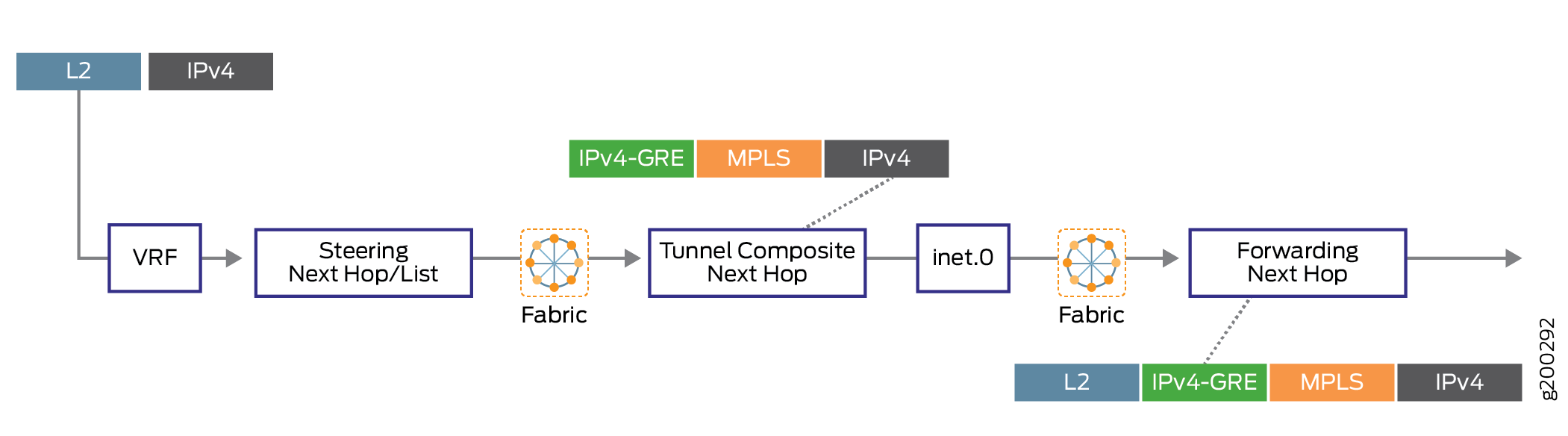
현지화가 지원되므로 다음 홉 기반의 동적 터널 상태는 앵커 패킷 포워딩 엔진로 현지화되고 다른 패킷 포워딩 엔진는 트래픽을 터널 앵커로 스티어링하기 위한 터널 상태를 갖습니다.
그림 4 는 현지화가 없는 다음 홉 기반 동적 터널의 전달 경로를 보여줍니다.
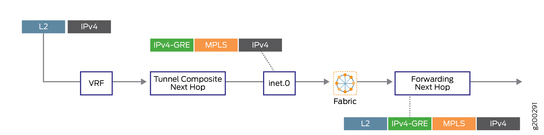
그림 5 는 현지화된 다음 홉 기반 동적 터널의 전달 경로를 보여줍니다.
다음 홉 기반 동적 터널 현지화 구성
새로 생성된 다음 홉 기반 동적 터널 또는 기존의 비로컬 동적 터널에 대해 현지화 지원을 구성할 수 있습니다.
새로운 다음 홉 기반 동적 터널에 대한 현지화 구성
다음 홉 기반 동적 터널의 현지화는 정책 기반 접근 방식을 사용하여 접두사 그룹을 지정합니다. 즉, 경로 정책은 현지화 속성을 다음 홉 기반 동적 터널에 적용하는 데 사용됩니다. 동적 터널 속성 프로필은 정책을 사용하여 접두사 그룹과 연결하기 위해 라우팅 옵션 아래에 생성 및 구성됩니다.
-
동적 터널 프로파일 생성.
동적 터널 프로필은 터널 유형과 앵커 패킷 포워딩 엔진 정보를 지정합니다. 동적 터널의 현지화를 위해 여러 동적 터널 프로파일을 생성할 수 있습니다. 동적 터널 유형의 값은 GRE, UDP 또는 BGP-SIGNAL일 수 있습니다.
BGP-SIGNAL이 유효한 터널 유형은 아니지만, BGP-SIGNAL을 터널 유형으로 할당하면 BGP 신호 속성에서 생성된 터널이 현지화됩니다. BGP-SIGNAL을 사용할 때 터널 유형은 BGP가 TLV에서 보급하는 유형에 따라 결정됩니다. BGP-SIGNAL 터널은 항상 다음 홉 기반 터널입니다. BGP-SIGNAL에 의해 동적으로 생성된 GRE 터널은 사용자가 IFL을 사용하도록 GRE에 의해 생성된 터널을 수동으로 구성한 경우에도 항상 다음 홉 기반입니다.
앵커 패킷 포워딩 엔진 값은 앵커 패킷 포워딩 엔진의 라인 카드입니다(예: pfe-x/y/0). 이 정보는 명령 출력에서
show interfaces terse pfe*볼 수 있습니다.Sample Configuration:
[edit routing-options] dynamic-tunnels { dynamic-tunnel-attributes attribute-1 { dynamic-tunnel-type <GRE | UDP | BGP-SIGNAL>; dynamic-tunnel-anchor-pfe pfe-1/0/0; } } -
동적 터널 프로필을 접두사 목록에 연결합니다.
를 로 정책을
dynamic-tunnel-attributes구성하면 동적 터널이 접두사 목록에 연결됩니다. 정책from작업을 통해 BGP 경로의 접두사 범위, 커뮤니티 또는 소스 주소 등과 같은 일치하는 조건에 대해 지정된 속성을 가진 터널을 생성할 수 있습니다.Sample configuration:
[edit policy-options] policy-statement policy-name { term term { from { <route-filter | next-hop | community>>; } then { dynamic-tunnel-attributes <attribute-name>; } } } -
포포워딩 테이블 내보내기 정책 아래에 터널 정책을 포함합니다.
정책이 구성되면 정책 구문 분석을 위한 포워딩 테이블 내보내기 정책에 포함됩니다.
내보내기 정책을 사용하면 터널 속성이 경로와 연결됩니다. BGP의 경로가 해결을 위해 대기열에 있을 때마다 포워딩 테이블 내보내기 정책이 평가되고 적용된 필터를 기반으로 정책 모듈에서 터널 속성을 얻습니다. 그런 다음 획득한 터널 속성은 터널 복합 다음 홉의 형태로 다음 홉에 첨부됩니다. 패킷 포워딩 엔진 이름과 터널 유형을 기반으로 하는 해당 앵커 포워딩 구조가 생성되어 터널 복합 다음 홉이 전송되기 전에 포워딩 테이블로 전송됩니다. 그러나 어떤 속성도 터널 복합 다음 홉에 매핑되지 않는 경우, 현지화되지 않은 동적 터널과 유사하게 모든 패킷 포워딩 엔진에서 포워딩 구조가 생성됩니다.
Sample configuration:
[edit routing-options]
forwarding-table {
    export  dynamic-tunnel;
}
기존 다음 홉 기반 동적 터널에 대한 현지화 구성
동적 터널 속성을 즉석에서 변경하면 높은 메모리 사용률로 인해 FPC 충돌이 발생할 수 있습니다. 따라서 현지화를 구성하기 전에 동적 터널 구성을 비활성화하는 것이 좋습니다.
기존의 다음 홉 기반 동적 터널에 대한 터널 속성을 업데이트하려면 다음을 수행해야 합니다.
-
계층 수준에서 구성을 비활성화
dynamic-tunnels합니다[edit routing-options].Sample configuration:
[edit routing-options]
user@host# deactivate dynamic-tunnels
user@host# commit
-
필요에 따라 터널 속성을 변경합니다.
-
계층 수준에서 구성을 활성화
dynamic-tunnels합니다[edit routing-options].Sample configuration:
[edit routing-options]
user@host# activate dynamic-tunnels
user@host# commit
기존의 비로컬 다음 홉 기반 동적 터널에 대한 현지화 구성 방법:
기존의 비로컬 다음 홉 기반 동적 터널에 대한 현지화를 구성하기 위해 즉석에서 변경하면 높은 메모리 사용률로 인해 FPC 충돌이 발생할 수 있습니다. 따라서 현지화를 구성하기 전에 동적 터널 구성을 비활성화하는 것이 좋습니다.
-
계층 수준에서 구성을 비활성화
dynamic-tunnels합니다.[edit routing-options] -
터널 속성 프로필을 생성하고 새로운 다음 홉 기반 동적 터널과 유사하게 동적 터널을 현지화하기 위한 정책을 추가합니다.
-
구성을 활성화합니다
dynamic-tunnels.
현지화된 다음 홉 기반 동적 터널 문제 해결
다음 홉 기반 동적 터널의 현지화와 함께 터널 복합 다음 홉은 앵커 패킷 포워딩 엔진 ID와 연결됩니다. 계층 수준에서 [edit routing-options] 다음 traceroute 구성 문은 현지화된 동적 터널의 문제 해결에 도움이 됩니다.
-
dynamic-tunnels traceoptions flag all- DTM에서 터널의 생성 및 삭제를 추적합니다. -
resolution traceoptions flag tunnel—BGP 경로에서 확인자 작업을 추적합니다. -
forwarding-table traceoptions flag all- 커널로 전송된 터널을 추적합니다. -
traceoptions flag all—경로 학습 프로세스 추적.
다음 명령을 사용하여 경로가 현지화된 다음 홉 기반 동적 터널을 사용하고 있는지 확인할 수 있습니다.
-
show route prefix extensive- 간접 다음 홉을 획득합니다.
예를 들면 다음과 같습니다.
user@host> show route 1.2.3.4 extensive MPLS-over-UDP-PE1.inet.0: 24 destinations, 26 routes (24 active, 0 holddown, 0 hidden) 1.2.3.4/32 (1 entry, 1 announced) TSI: KRT in-kernel 1.2.3.4/32 -> {indirect(1048577)} Page 0 idx 1, (group pe1-ce1 type External) Type 1 val 0xb209a78 (adv_entry) Advertised metrics: Nexthop: Self AS path: [100] I Communities: target:600:1 encapsulation:mpls-in-udp(0xd) -
show krt indirect-next-hop index indirect-next-hop detail- 간접 다음 홉의 세부 출력에서 앵커 패킷 포워딩 엔진 필드를 확인합니다.
예를 들면 다음과 같습니다.
user@host> show krt indirect-next-hop index 1048577 detail
Indirect Nexthop detail:
Index: 1048577 Protocol next-hop address: 1.1.1.6
  RIB Table: bgp.l3vpn.0            	Label: Push 299808
  Policy Version: 2                 	References: 11
  Locks: 3                          	0xb227980
  Flags: 0x0
  INH Session ID: 0x0
  Ref RIB Table: unknown
  Export policy detail:
 	(Dynamic tunnel hash : 309985522)
    	Tunnel type: UDP, Reference count: 4, nhid: 1016
    	Destination address: 1.1.1.6, Source address: 1.1.1.2
    	Anchored-PFE: pfe-1/0/0
    	VPN Label: Push 299808, TTL action: prop-ttl
  	IGP FRR Interesting proto count : 11
  	Chain IGP FRR Node Num      	: 1
     	IGP Resolver node(hex)   	: 0xc838b94
     	IGP Route handle(hex)    	: 0xb1d7674  	IGP rt_entry protocol    	: Tunnel
     	IGP Actual Route handle(hex) : 0x0        	IGP Actual rt_entry protocol : Any
다음 홉 기반 동적 터널 현지화에 지원되지 않는 기능
Junos OS는 다음 홉 기반 동적 터널에 대한 현지화와 함께 다음 기능을 지원하지 않습니다.
-
계층 수준에서 연결된 복합 다음 홉입니다.
[edit routing-options forwarding-table chained-composite-next-hop ingress l3vpn] -
앵커 패킷 포워딩 엔진 복원력.
현지화된 다음 홉 기반 동적 터널에 대한 복원력 지원은 없습니다. 다음 홉 기반 동적 터널을 현지화한 후, 앵커 패커 전달 엔진은 디바이스에서 지정된 터널을 처리하는 단일 엔티티가 됩니다. 앵커 패커 전달 엔진 복원력은 지원되지 않지만, 게이트웨이 디바이스의 경우, 게이트웨이 디바이스의 중복은 터널 복합 다음 홉이 위임된 패커 전달 엔진이 다운될 때 트래픽을 중복 게이트웨이 디바이스로 다시 라우팅해야 합니다. 라우팅 프로토콜 프로세스는 패커 포워딩 엔진의 상태를 모니터링하고, 해당 패커 포워딩 엔진에 고정된 터널 복합 다음 홉을 가리키는 모든 경로의 BGP 광고를 철회합니다.
앵커된 패킷 포워딩 엔진에만 본격적인 터널 복합 다음 홉이 있으며, 다른 모든 패킷 전달 엔진에는 앵커 패킷 포워딩 엔진으로 트래픽을 포워딩하는 스티어링 항목만 있습니다. 앵커 FPC가 다운되어도 이러한 스티어링 항목은 철회되지 않습니다.
-
다음 홉 기반 동적 터널의 현지화는 논리적 시스템에서 지원되지 않습니다.
-
IPv6는 다음 홉 기반 동적 터널의 현지화로 지원되지 않습니다.
-
현지화
show dynamic-tunnels database summary를 사용하면 앵커 패킷 포워딩 엔진 라인 카드의 상태가 켜지지 않을 때 명령이 정확한 터널 요약을 표시하지 않습니다. 해결 방법으로 andshow dynamic-tunnels database terse명령 출력을show dynamic-tunnels database사용합니다.
IP-over-IP 캡슐화를 사용한 다음 홉 기반 동적 터널링 개요
이점
IP-over-IP 터널링은 다음과 같은 이점을 제공합니다.
-
Alternative to MPLS over UDP- 서비스당 전용 디바이스가 있는 IP 서비스를 제공하기 위해 MPLS-over-UDP 터널링의 대안으로 사용할 수 있습니다.
-
Ability to steer specific traffic- MPLS 터널이 아닌 IP 터널을 통해 특정 트래픽을 조정하도록 경로를 필터링할 수 있기 때문에 MPLS 및 IP 네트워크가 공존할 때 원활한 마이그레이션이 가능합니다.
-
Ability to support tunnels at increasing scale- BGP 컨트롤 플레인을 사용한 동적 터널 생성은 대규모로 터널 생성을 용이하게 할 수 있습니다.
IP-over-IP 동적 다음 홉 기반 터널링이란 무엇입니까?
IP 네트워크에는 에지 디바이스와 코어 디바이스가 포함됩니다. 이러한 디바이스 간에 더 높은 확장성과 안정성을 달성하려면 오버레이 캡슐화를 사용하여 에지 디바이스가 상호 작용하는 외부 네트워크로부터 코어 네트워크를 논리적으로 격리해야 합니다.
Junos OS 릴리스 20.3R1부터 IP-over-IP 캡슐화를 지원하여 IP 전송 네트워크를 통한 IP 오버레이 구축을 용이하게 합니다. IP over IP는 더 높은 규모를 지원하기 위해 다음 홉 기반 인프라에 의존합니다. 이 기능은 IPv6 및 IPv4 페이로드의 IPv4 캡슐화를 지원합니다. 지원되는 다른 오버레이 캡슐화 중에서 IP-over-IP 캡슐화는 다음을 허용하는 유일한 종류입니다.
-
내부 페이로드를 구문 분석하고 해시 계산에 내부 패킷 필드를 사용하는 전송 디바이스
-
처리량 감소 없이 터널로 들어오고 나가는 트래픽을 라우팅하는 고객 에지 디바이스
MX 시리즈 라우터에서 라우팅 프로토콜 데몬(RPD)은 터널 복합 다음 홉과 함께 캡슐화 헤더를 전송하고 패킷 포워딩 엔진(PFE)은 터널 대상 주소를 찾아 패킷을 전달합니다. PTX 시리즈 라우터 및 QFX10000 스위치에서 RPD는 완전히 확인된 다음 홉 기반 터널을 패킷 포워딩 엔진으로 보냅니다. BGP 프로토콜은 경로를 배포하고 동적 터널을 신호하는 데 사용됩니다.
다음 그림은 IPv4 또는 IPv6 트래픽이 R-2와 R-4 사이에 설정된 IP over IP 터널을 통해 R-1에서 R-5로 전송되는 방법을 보여줍니다.
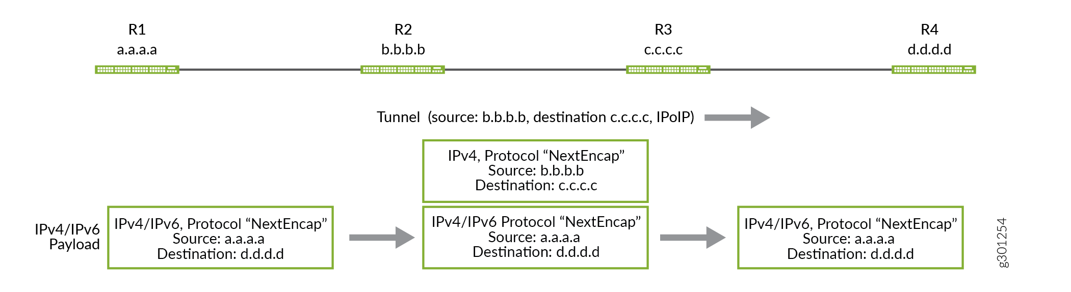
IP-over-IP 터널 연결
Junos OS 릴리스 21.3R1에서는 MX240, MX480, MX960, PTX1000, PTX10008, PTX10016, QFX10002에 IP-over-IP 터널 연결이 도입되었습니다. 이 기능을 사용하여 디바이스에서 IP-over-IP 터널을 종료하고 동일한 디바이스에서 다른 터널을 시작할 수 있습니다. 디바이스가 IP-over-IP 패킷을 수신하면 외부 패킷 헤더를 캡슐화 해제하고 내부 패킷 조회가 발생합니다. 그런 다음 내부 IP 패킷 헤더는 동일한 디바이스의 다른 터널을 가리키며, 여기서 동일한 디바이스는 다른 IP-over-IP 헤더로 패킷을 다시 캡슐화합니다.
예: 다음 홉 기반 IP-Over-IP 동적 터널 구성
IP-over-IP 캡슐화를 사용하여 다음 홉 기반 터널을 구성하는 방법에 대해 알아봅니다.
- 요구 사항
- 개요
- 프로토콜 다음 홉을 사용하여 IP-over-IP 동적 터널 구성
- 예: LDP 터널가 있는 MPLS 환경에서 IPoIP 터널 구성, 정적 구성을 사용하여 inetcolor.0을 통해 해결
- 예: MPLS 클라우드에서 LDP 터널로 IPoIP 터널 구성, BGP 신호를 사용하여 inetcolor.0을 통해 해결됨
- 검증
요구 사항
이 예에서 사용되는 하드웨어 및 소프트웨어 구성 요소는 다음과 같습니다.
-
5개의 MX 시리즈 라우터.
-
Junos OS 릴리스 20.3R1 이상 버전.
- 지원되는 플랫폼은 기능 탐색기를 참조하십시오.
개요
Junos OS 릴리스 20.3R1부터 IP-over-IP 캡슐화를 지원하여 IP 전송 네트워크를 통한 IP 오버레이 구축을 용이하게 합니다. 이 예는 OSPF 코어를 통해 연결된 R2와 R4 간의 IBGP 피어링을 통해 프로토콜 다음 홉(PNH)이 있는 디바이스 간에 유니캐스트 IP-over-IP 터널을 설정하여 경로를 교환하고 동적 터널을 신호하는 것을 보여줍니다.
토폴로지
그림 1은 5개의 디바이스가 있는 IP-over-IP 시나리오를 보여줍니다.
이 예에서는 R2와 R4 사이에 설정된 IP-over-IP 동적 터널을 통해 R1에서 R5로 또는 그 반대로 경로를 교환하고 있습니다. 프로토콜 IS-IS를 사용하여 R1의 경로는 R2로 내보내고 R5의 경로는 R4로 내보냅니다. R2에서 R4까지 유니캐스트 IPIP 터널 Tunnel-01 과 R4에서 R2까지 또 다른 터널 Tunnel-01 을 구성합니다. 피어 디바이스의 구성된 대상 네트워크의 네트워크 마스크 내에서 생성되는 경로 접두사는 터널 및 터널 경로와 반대 방향의 트래픽 흐름을 생성하는 데 사용됩니다.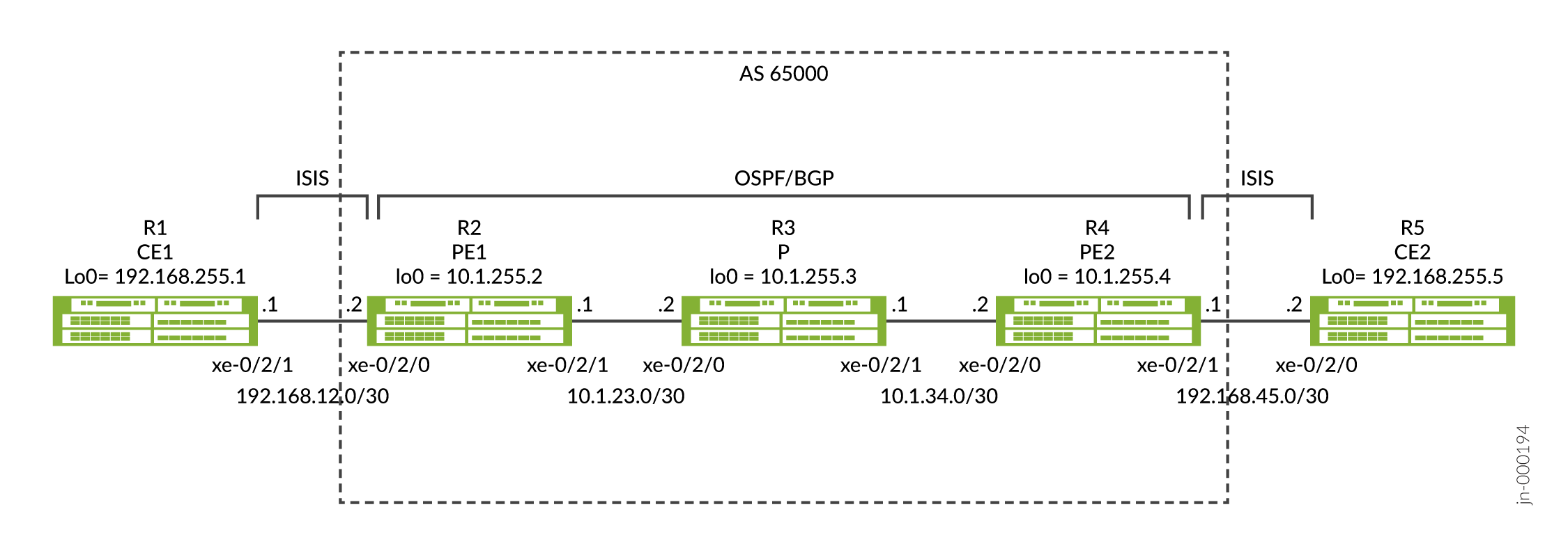
프로토콜 다음 홉을 사용하여 IP-over-IP 동적 터널 구성
CLI 빠른 구성
이 예를 빠르게 구성하려면, 아래 명령을 복사하여 텍스트 파일로 붙여 넣은 다음 모든 라인브레이크를 제거하고, 네트워크 구성을 일치하는 데 필요한 세부 사항을 변경하고, 계층 수준에서 [edit] 명령을 복사하여 CLI에 붙여 넣은 다음, 구성 모드에서 commit을 입력합니다.
R1
set interfaces xe-0/2/0 unit 0 description R1-to-R2
set interfaces xe-0/2/0 unit 0 family inet address 192.168.12.1/30
set interfaces xe-0/2/0 unit 0 family iso
set interfaces lo0 unit 0 family inet address 192.168.255.1/32
set interfaces lo0 unit 0 family iso address 49.0001.1920.1682.5501.00
set routing-options router-id 192.168.255.1
set protocols isis interface xe-0/2/0.0
set protocols isis interface lo0.0
set protocols isis level 1 disable
R2
set interfaces xe-0/2/0 description R2-to-R1
set interfaces xe-0/2/0 unit 0 family inet address 192.168.12.2/30
set interfaces xe-0/2/0 unit 0 family iso
set interfaces xe-0/2/1 description R2-to-R3
set interfaces xe-0/2/1 unit 0 family inet address 10.1.23.1/30
set interfaces lo0 unit 0 family inet address 10.1.255.2/32
set interfaces lo0 unit 0 family iso address 49.0001.0010.1255.0002.00
set policy-options policy-statement export-bgp term t1 from protocol bgp
set policy-options policy-statement export-bgp term t1 then accept
set policy-options policy-statement export-isis term t1 from protocol isis
set policy-options policy-statement export-isis term t1 then next-hop self
set policy-options policy-statement export-isis term t1 then accept
set routing-options resolution rib inet.0 resolution-ribs inet.3
set routing-options router-id 10.1.255.2
set routing-options autonomous-system 65000
set routing-options dynamic-tunnels Tunnel-01 source-address 10.1.255.2
set routing-options dynamic-tunnels Tunnel-01 ipip
set routing-options dynamic-tunnels Tunnel-01 destination-networks 10.1.255.0/24
set protocols bgp group iBGP type internal
set protocols bgp group iBGP local-address 10.1.255.2
set protocols bgp group iBGP family inet unicast
set protocols bgp group iBGP export export-isis
set protocols bgp group iBGP neighbor 10.1.255.4
set protocols isis interface xe-0/2/0.0
set protocols isis interface lo0.0
set protocols isis level 1 disable
set protocols isis export export-bgp
set protocols ospf area 0.0.0.0 interface xe-0/2/1.0
set protocols ospf area 0.0.0.0 interface lo0.0
R3
set interfaces xe-0/2/0 unit 0 description R3-to-R2
set interfaces xe-0/2/0 unit 0 family inet address 10.1.23.2/30
set interfaces xe-0/2/1 unit 0 description R3-to-R4
set interfaces xe-0/2/1 unit 0 family inet address 10.1.34.1/30
set interfaces lo0 unit 0 family inet address 10.1.255.3/32
set routing-options router-id 10.1.255.3
set protocols ospf area 0.0.0.0 interface xe-0/2/0.0
set protocols ospf area 0.0.0.0 interface xe-0/2/1.0
set protocols ospf area 0.0.0.0 interface lo0.0 passive
R4
set interfaces xe-0/2/0 unit 0 description R4-to-R3
set interfaces xe-0/2/0 unit 0 family inet address 10.1.34.2/30
set interfaces xe-0/2/1 unit 0 description R4-to-R5
set interfaces xe-0/2/1 unit 0 family inet address 192.168.45.1/30
set interfaces xe-0/2/1 unit 0 family iso
set interfaces lo0 unit 0 family inet address 10.1.255.4/32
set interfaces lo0 unit 0 family iso address 49.0001.0010.1255.0004.00
set policy-options policy-statement export-bgp term t1 from protocol bgp
set policy-options policy-statement export-bgp term t1 then accept
set policy-options policy-statement export-isis term t1 from protocol isis
set policy-options policy-statement export-isis term t1 then next-hop self
set policy-options policy-statement export-isis term t1 then accept
set routing-options resolution rib inet.0 resolution-ribs inet.3
set routing-options router-id 10.1.255.4
set routing-options autonomous-system 65000
set routing-options dynamic-tunnels Tunnel-01 source-address 10.1.255.4
set routing-options dynamic-tunnels Tunnel-01 ipip
set routing-options dynamic-tunnels Tunnel-01 destination-networks 10.1.255.0/24
set protocols bgp group iBGP type internal
set protocols bgp group iBGP local-address 10.1.255.4
set protocols bgp group iBGP family inet unicast
set protocols bgp group iBGP export export-isis
set protocols bgp group iBGP neighbor 10.1.255.2
set protocols isis interface xe-0/2/1.0
set protocols isis interface lo0.0
set protocols isis level 1 disable
set protocols isis export export-bgp
set protocols ospf area 0.0.0.0 interface xe-0/2/0.0
set protocols ospf area 0.0.0.0 interface lo0.0
R5
set interfaces xe-0/2/0 unit 0 description R5-to-R4
set interfaces xe-0/2/0 unit 0 family inet address 192.168.45.2/30
set interfaces xe-0/2/0 unit 0 family iso
set interfaces lo0 unit 0 family inet address 192.168.255.5/32
set interfaces lo0 unit 0 family iso address 49.0001.1920.1682.5505.00
set routing-options router-id 192.168.255.5
set protocols isis interface xe-0/2/0.0
set protocols isis interface lo0.0
set protocols isis level 1 disable
프로토콜 다음 홉으로 IP-IP 동적 터널 구성
R1에 대한 단계별 절차
R1과 R5는 구성이 유사하므로 R1에 대한 단계별 절차만 보여 드리겠습니다.
-
R1에서 구성 모드로 들어갑니다.
-
R2 및 인터페이스 lo0에 연결된 인터페이스를 구성합니다. 패밀리
inet및iso. 프로토콜 IS-IS에는 패밀리iso가 필요합니다.[edit] user@R1# set interfaces xe-0/2/0 unit 0 description R1-to-R2 user@R1# set interfaces xe-0/2/0 unit 0 family inet address 192.168.12.1/30 user@R1# set interfaces xe-0/2/0 unit 0 family iso user@R1# set interfaces lo0 unit 0 family inet address 192.168.255.1/32 user@R1# set interfaces lo0 unit 0 family iso address 49.0001.1920.1682.5501.00
-
라우터 ID를 구성합니다.
[edit]
user@R1# set routing-options router-id 192.168.255.1
-
프로토콜 IS-IS를 구성합니다. 경로는 IS-IS 프로토콜을 사용하여 R1과 R2 사이에 보급됩니다.
[edit]
user@R1# set protocols isis interface xe-0/2/0.0
user@R1# set protocols isis interface lo0.0
user@R1# set protocols isis level 1 disable
-
구성 모드에서 R1로 들어갑니다
commit.
R2에 대한 단계별 절차
R2와 R4는 구성이 비슷하므로 R2에 대한 단계별 절차만 보여 드리겠습니다.
-
R2에서 구성 모드로 들어갑니다.
-
R1 및 R3 및 인터페이스 lo0에 연결된 인터페이스를 구성합니다. R1 및 lo0에 연결된 인터페이스에서 패밀리
inet와iso모두를 구성해야 합니다.[edit] user@R2# set interfaces xe-0/2/0 description R2-to-R1 user@R2# set interfaces xe-0/2/0 unit 0 family inet address 192.168.12.2/30 user@R2# set interfaces xe-0/2/0 unit 0 family iso user@R2# set interfaces xe-0/2/1 description R2-to-R3 user@R2# set interfaces xe-0/2/1 unit 0 family inet address 10.1.23.1/30 user@R2# set interfaces lo0 unit 0 family inet address 10.1.255.2/32 user@R2# set interfaces lo0 unit 0 family iso address 49.0001.0010.1255.0002.00
-
R1에 연결된 인터페이스에 대한 프로토콜 IS-IS를 구성합니다. BGP 경로를 IS-IS로 보급하는 내보내기 정책은 정책 구성 단계에 표시됩니다.
[edit]
user@R2# set protocols isis interface xe-0/2/0.0
user@R2# set protocols isis interface lo0.0
user@R2# set protocols isis level 1 disable
user@R2# set protocols isis export export-bgp
-
lo0 도달 가능성을 위해 R3에 연결된 인터페이스에 대해 OSPF 프로토콜을 구성합니다.
[edit]
user@R2# set protocols ospf area 0.0.0.0 interface xe-0/2/1.0
user@R2# set protocols ospf area 0.0.0.0 interface lo0.0
-
R2와 R4 사이의 및
autonomous-system및 IBGP를 구성router-id합니다. IS-IS 경로를 BGP로 보급하는 내보내기 정책은 정책 구성 단계에 표시됩니다.[edit] user@R2# set routing-options router-id 10.1.255.2 user@R2# set routing-options autonomous-system 65000 user@R2# set protocols bgp group iBGP type internal user@R2# set protocols bgp group iBGP local-address 10.1.255.2 user@R2# set protocols bgp group iBGP family inet unicast user@R2# set protocols bgp group iBGP export export-isis user@R2# set protocols bgp group iBGP neighbor 10.1.255.4
-
이전 단계에서 적용한 BGP 및 IS-IS 내보내기 정책을 구성합니다. 이
export-bgp정책은 BGP 경로를 IS-IS로 보급하기 위한 내보내기로 프로토콜 IS-IS에 적용되며, 정책은export-isisIS-IS 경로를 BGP로 보급하기 위한 내보내기로 BGP에 적용됩니다. 다음 홉 self 옵션을 사용하면 R2가 R1의 인터페이스 다음 홉 대신 R2를 다음 홉으로 사용하여 BGP에 IS-IS 경로를 보급할 수 있습니다.[edit] user@R2# set policy-options policy-statement export-bgp term t1 from protocol bgp user@R2# set policy-options policy-statement export-bgp term t1 then accept user@R2# set policy-options policy-statement export-isis term t1 from protocol isis user@R2# set policy-options policy-statement export-isis term t1 then next-hop self user@R2# set policy-options policy-statement export-isis term t1 then accept
-
R2에서 R4까지 IP-IP 동적 터널 Tunnel-01 을 구성합니다. 구성 옵션을
resolution-ribs inet.3사용하면 inet.3에서 경로 확인이 수행되며 터널을 설정하는 데 필요합니다.[edit] user@R2# set routing-options resolution rib inet.0 resolution-ribs inet.3 user@R2# set routing-options dynamic-tunnels Tunnel-01 source-address 10.1.255.2 user@R2# set routing-options dynamic-tunnels Tunnel-01 ipip user@R2# set routing-options dynamic-tunnels Tunnel-01 destination-networks 10.1.255.0/24
-
(선택 사항) - R2에서 R4로의 IP-IP 동적 터널 Tunnel-01 에 대한 대체 구성. 를
resolution-ribs inet.3구성하는 대신 터널 엔드포인트에 대한 경로에 대해 프로토콜 다음 홉 기본 설정보다 낮은 터널 기본 설정을 구성할 수 있습니다. R4의 경로는 OSPF를 사용하여 학습되며 선호는 10이며 터널의 기본 선호는 305입니다. 최단 경로 우선(OSPF) 기본 설정보다 낮은 터널 기본 설정을 구성하면 터널을 선호하고 설정할 수 있습니다.[edit] user@R2# set routing-options dynamic-tunnels Tunnel-01 source-address 10.1.255.2 user@R2# set routing-options dynamic-tunnels Tunnel-01 ipip user@R2# set routing-options dynamic-tunnels Tunnel-01 destination-networks 10.1.255.0/24 preference 9
-
R2의 구성 모드에서 진입합니다
commit.
R3에 대한 단계별 절차
-
R3에서 구성 모드로 들어갑니다.
-
R2 및 R4와 인터페이스 lo0에 연결된 인터페이스를 구성합니다.
[edit]
user@R3# set interfaces xe-0/2/0 unit 0 description R3-to-R2
user@R3# set interfaces xe-0/2/0 unit 0 family inet address 10.1.23.2/30
user@R3# set interfaces xe-0/2/1 unit 0 description R3-to-R4
user@R3# set interfaces xe-0/2/1 unit 0 family inet address 10.1.34.1/30
user@R3# set interfaces lo0 unit 0 family inet address 10.1.255.3/32
-
라우터 ID를 구성합니다.
[edit]
user@R3# set routing-options router-id 10.1.255.3
-
lo0 도달성을 위해 R2 및 R4에 연결된 인터페이스에 대해 OSPF 프로토콜을 구성합니다.
[edit]
user@R3# set protocols ospf area 0.0.0.0 interface xe-0/2/0.0
user@R3# set protocols ospf area 0.0.0.0 interface xe-0/2/1.0
user@R3# set protocols ospf area 0.0.0.0 interface lo0.0 passive
-
R3 디바이스의 구성 모드에서 진입합니다
commit.
결과
다음과 같이 디바이스의 아래 구성을 확인하여 구성을 검증합니다:
R2에서 구성을 확인하는 방법은 다음과 같습니다.
user@R2# show interfaces
xe-0/2/0 {
    description R2-to-R1;
    unit 0 {
        family inet {
            address 192.168.12.2/30;
        }
        family iso;
    }
}
xe-0/2/1 {
    description R2-to-R3;
    unit 0 {
        family inet {
            address 10.1.23.1/30;
        }
    }
}
lo0 {
    unit 0 {
        family inet {
            address 10.1.255.2/32;
        }
        family iso {
            address 49.0001.0010.1255.0002.00;
        }
    }
}
user@R2# show routing-options
resolution {
    rib inet.0 {
        resolution-ribs inet.3;
    }
}
router-id 10.1.255.2;
autonomous-system 65000;
dynamic-tunnels {
    Tunnel-01 {
        source-address 10.1.255.2;
        ipip;
        destination-networks {
            10.1.255.0/24;
        }
    }
}
user@R2# show protocols
bgp {
    group iBGP {
        type internal;
        local-address 10.1.255.2;
        family inet {
            unicast;
        }
        export export-isis;
        neighbor 10.1.255.4;
    }
}
isis {
    interface xe-0/2/0.0;
    interface lo0.0;
    level 1 disable;
    export export-bgp;
}
ospf {
    area 0.0.0.0 {
        interface xe-0/2/1.0;
        interface lo0.0;
    }
}
user@R2# show policy-options
policy-statement export-bgp {
    term t1 {
        from protocol bgp;
        then accept;
    }
}
policy-statement export-isis {
    term t1 {
        from protocol isis;
        then {
            next-hop self;
            accept;
        }
    }
}
검증
동적 터널 데이터베이스 확인
목적
동적 터널 데이터베이스 정보를 확인하려면 운영 모드 명령을 사용합니다 show dynamic-tunnels database .
작업
user@R2> show dynamic-tunnels database
*- Signal Tunnels #- PFE-down
Table: inet.3

Destination-network: 10.1.255.0/24

Tunnel to: 10.1.255.4/32
  Reference count: 3
  Next-hop type: IPoIP (forwarding-nexthop)
    Source address: 10.1.255.2
    Next hop: tunnel-composite, 0x76b6c50, nhid 515
      Reference count: 2
      Ingress Route: [OSPF] 10.1.255.4/32, via metric 2
      Traffic Statistics: Packets 0, Bytes 0
      State: Up
  Aggregate Traffic Statistics:
    Tunnel Encapsulation: Dest 10.1.255.4, Src 10.1.255.2, IPoIP, Tunnel-Id 1
Traffic Statistics: Packets 0, Bytes 0 user@R4> show dynamic-tunnels database
*- Signal Tunnels #- PFE-down
Table: inet.3
Destination-network: 10.1.255.0/24
Tunnel to: 10.1.255.2/32
Reference count: 3
Next-hop type: IPoIP (forwarding-nexthop)
Source address: 10.1.255.4
Next hop: tunnel-composite, 0x76b6c50, nhid 513
Reference count: 2
Ingress Route: [OSPF] 10.1.255.2/32, via metric 2
Traffic Statistics: Packets 0, Bytes 0
State: Up
Aggregate Traffic Statistics:
Tunnel Encapsulation: Dest 10.1.255.2, Src 10.1.255.4, IPoIP, Tunnel-Id 1
Traffic Statistics: Packets 0, Bytes 0의미
출력은 R2(192.168.0.21 소스)와 R4(192.168.0.41 대상) 사이에 IPoIP 터널이 설정되었고 R4(192.168.0.41 소스)와 R2(192.168.0.21 대상) 사이에 다른 IPoIP 터널이 설정되었음을 나타냅니다.
inet.3에서 경로 테이블 확인
목적
inet.3 테이블에서 생성된 경로를 확인하려면 운영 모드 명령을 사용합니다 show route table inet.3 .
작업
user@R2> show route table inet.3

inet.3: 2 destinations, 2 routes (2 active, 0 holddown, 0 hidden)
+ = Active Route, - = Last Active, * = Both

10.1.255.0/24      *[Tunnel/305] 02:02:44
                       Tunnel
10.1.255.4/32      *[Tunnel/305] 02:02:44, metric 2
Tunnel Composite, IPoIP (src 10.1.255.2 dest 10.1.255.4)user@R4> show route table inet.3
inet.3: 2 destinations, 2 routes (2 active, 0 holddown, 0 hidden)
+ = Active Route, - = Last Active, * = Both
10.1.255.0/24 *[Tunnel/305] 6d 01:35:50
Tunnel
10.1.255.2/32 *[Tunnel/305] 6d 01:35:48, metric 2
Tunnel Composite, IPoIP (src 10.1.255.4 dest 10.1.255.2)의미
출력은 터널을 사용할 BGP 트래픽을 해결하는 데 사용되는 경로를 나타냅니다.
터널을 사용하여 BGP 경로 확인
목적
R1 및 R5에 대해 R2 및 R4에서 수신된 BGP 경로가 터널을 사용하고 있는지 확인합니다.
작업
user@R2> show route protocol bgp

inet.0: 17 destinations, 17 routes (17 active, 0 holddown, 0 hidden)
+ = Active Route, - = Last Active, * = Both

192.168.255.5/32   *[BGP/170] 02:42:48, MED 10, localpref 100, from 10.1.255.4
                      AS path: I, validation-state: unverified
                    >  via Tunnel Composite, IPoIP (src 10.1.255.2 dest 10.1.255.4)

inet.3: 2 destinations, 2 routes (2 active, 0 holddown, 0 hidden)

iso.0: 1 destinations, 1 routes (1 active, 0 holddown, 0 hidden)

inet6.0: 1 destinations, 1 routes (1 active, 0 holddown, 0 hidden)
user@R4> show route protocol bgp

inet.0: 17 destinations, 17 routes (17 active, 0 holddown, 0 hidden)
+ = Active Route, - = Last Active, * = Both

192.168.255.1/32   *[BGP/170] 00:13:30, MED 10, localpref 100, from 10.1.255.2
                      AS path: I, validation-state: unverified
                    >  via Tunnel Composite, IPoIP (src 10.1.255.4 dest 10.1.255.2)

inet.3: 2 destinations, 2 routes (2 active, 0 holddown, 0 hidden)

iso.0: 1 destinations, 1 routes (1 active, 0 holddown, 0 hidden)

inet6.0: 1 destinations, 1 routes (1 active, 0 holddown, 0 hidden)
의미
출력은 R2가 R5로 가는 BGP 경로에 터널을 사용하고 R4가 R1로 가는 BGP 경로에 터널을 사용하고 있음을 나타냅니다.
엔드 투 엔드 도달 가능성 확인
목적
R1이 운영 모드 명령을 사용하여 ping 192.168.255.5 source 192.168.255.1 count 2 R5를 ping할 수 있는지 확인합니다.
작업
user@R1>ping 192.168.255.5 source 192.168.255.1 count 2
PING 192.168.255.5 (192.168.255.5): 56 data bytes
64 bytes from 192.168.255.5: icmp_seq=0 ttl=62 time=5.565 ms
64 bytes from 192.168.255.5: icmp_seq=1 ttl=62 time=5.957 ms

--- 192.168.255.5 ping statistics ---
2 packets transmitted, 2 packets received, 0% packet loss
round-trip min/avg/max/stddev = 5.565/5.761/5.957/0.196 ms
의미
R1의 출력은 R1이 R5를 ping할 수 있음을 보여줍니다.
예: LDP 터널가 있는 MPLS 환경에서 IPoIP 터널 구성, 정적 구성을 사용하여 inetcolor.0을 통해 해결
기본적으로 MPLS는 IP보다 더 높은 선호도를 갖습니다. 예를 들어, R2, R3 및 R4 사이에 MPLS 및 LDP가 구성된 경우, 여기서 R2는 LDP를 통해 R4와 함께 도달할 수 있으며, R2의 경로는 선호가 더 높기 때문에 IP-over-IP 대신 LDP를 통해 해결됩니다.
LDP 대신 IP-over-IP를 통해 특정 경로를 확인하려면 IP-over-IP가 더 높은 선호를 갖는 inetcolor 테이블을 만들고 BGP가 inet3 테이블 대신 inetcolor 테이블을 통해 해당 경로를 해결하도록 설정하면 됩니다. 다음 예제에서는 정적 구성을 사용하여 이를 수행하는 방법을 보여줍니다.
토폴로지
이 예에서는 R2와 R4 사이에 설정된 IP-over-IP 동적 터널을 통해 R1에서 R5로 또는 그 반대로 경로를 교환하고 있습니다. 프로토콜 IS-IS를 사용하여 R1의 경로는 R2로 내보내고 R5의 경로는 R4로 내보냅니다. R2에서 R4까지 유니캐스트 IPIP 터널 Tunnel-01 과 R4에서 R2까지 또 다른 터널 Tunnel-01 을 구성합니다. 피어 디바이스의 구성된 대상 네트워크의 네트워크 마스크 내에서 생성되는 경로 접두사는 터널의 경로와 반대 방향으로 터널 및 트래픽 흐름을 생성하는 데 사용됩니다.
CLI 빠른 구성
R1
set interfaces xe-0/2/0 unit 0 description R1-to-R2
set interfaces xe-0/2/0 unit 0 family inet address 192.168.12.1/30
set interfaces xe-0/2/0 unit 0 family iso
set interfaces lo0 unit 0 family inet address 192.168.255.1/32
set interfaces lo0 unit 0 family iso address 49.0001.1920.1682.5501.00
set routing-options router-id 192.168.255.1
set protocols isis interface xe-0/2/0.0
set protocols isis interface lo0.0
set protocols isis level 1 disable
R2
set interfaces xe-0/2/0 description R2-to-R1
set interfaces xe-0/2/0 unit 0 family inet address 192.168.12.2/30
set interfaces xe-0/2/0 unit 0 family iso
set interfaces xe-0/2/1 description R2-to-R3
set interfaces xe-0/2/1 unit 0 family inet address 10.1.23.1/30
set interfaces xe-0/2/1 unit 0 family mpls
set interfaces lo0 unit 0 family inet address 10.1.255.2/32
set interfaces lo0 unit 0 family iso address 49.0001.0010.1255.0002.00
set policy-options policy-statement export-bgp term t1 from protocol bgp
set policy-options policy-statement export-bgp term t1 then accept
set policy-options policy-statement export-isis term t1 from protocol isis
set policy-options policy-statement export-isis term t1 then next-hop self
set policy-options policy-statement export-isis term t1 then accept
set policy-options policy-statement ipip-tunnel-color term term-01 from route-filter 192.168.255.5/32 exact
set policy-options policy-statement ipip-tunnel-color term term-01 then community add red
set policy-options policy-statement ipip-tunnel-color term term-01 then accept
set policy-options policy-statement set-dynamic-tunnel-ep term t1 from route-filter 10.1.255.4/32 exact
set policy-options policy-statement set-dynamic-tunnel-ep term t1 then tunnel-end-point-address 10.1.255.4
set policy-options policy-statement set-dynamic-tunnel-ep term t1 then accept
set policy-options community red members color:0:100
set routing-options router-id 10.1.255.2
set routing-options autonomous-system 65000
set routing-options dynamic-tunnels Tunnel-01 source-address 10.1.255.2
set routing-options dynamic-tunnels Tunnel-01 ipip
set routing-options dynamic-tunnels Tunnel-01 destination-networks 10.1.255.0/24 dyn-tunnel-attribute-policy set-dynamic-tunnel-ep
set routing-options dynamic-tunnels Tunnel-01 destination-networks 10.1.255.0/24 colors 100
set protocols bgp group iBGP type internal
set protocols bgp group iBGP local-address 10.1.255.2
set protocols bgp group iBGP import ipip-tunnel-color
set protocols bgp group iBGP family inet unicast extended-nexthop-color
set protocols bgp group iBGP export export-isis
set protocols bgp group iBGP neighbor 10.1.255.4
set protocols isis interface xe-0/2/0.0
set protocols isis interface lo0.0
set protocols isis level 1 disable
set protocols isis export export-bgp
set protocols ldp interface xe-0/2/1.0
set protocols mpls interface xe-0/2/1.0
set protocols ospf area 0.0.0.0 interface xe-0/2/1.0
set protocols ospf area 0.0.0.0 interface lo0.0
R3
set interfaces xe-0/2/0 unit 0 description R3-to-R2
set interfaces xe-0/2/0 unit 0 family inet address 10.1.23.2/30
set interfaces xe-0/2/0 unit 0 family mpls
set interfaces xe-0/2/1 unit 0 description R3-to-R4
set interfaces xe-0/2/1 unit 0 family inet address 10.1.34.1/30
set interfaces xe-0/2/1 unit 0 family mpls
set interfaces lo0 unit 0 family inet address 10.1.255.3/32
set routing-options router-id 10.1.255.3
set protocols ldp interface xe-0/2/0.0
set protocols ldp interface xe-0/2/1.0
set protocols mpls interface xe-0/2/0.0
set protocols mpls interface xe-0/2/1.0
set protocols ospf area 0.0.0.0 interface xe-0/2/0.0
set protocols ospf area 0.0.0.0 interface xe-0/2/1.0
set protocols ospf area 0.0.0.0 interface lo0.0 passive
R4
set interfaces xe-0/2/0 unit 0 description R4-to-R3
set interfaces xe-0/2/0 unit 0 family inet address 10.1.34.2/30
set interfaces xe-0/2/0 unit 0 family mpls
set interfaces xe-0/2/1 unit 0 description R4-to-R5
set interfaces xe-0/2/1 unit 0 family inet address 192.168.45.1/30
set interfaces xe-0/2/1 unit 0 family iso
set interfaces lo0 unit 0 family inet address 10.1.255.4/32
set interfaces lo0 unit 0 family iso address 49.0001.0010.1255.0004.00
set policy-options policy-statement export-bgp term t1 from protocol bgp
set policy-options policy-statement export-bgp term t1 then accept
set policy-options policy-statement export-isis term t1 from protocol isis
set policy-options policy-statement export-isis term t1 then next-hop self
set policy-options policy-statement export-isis term t1 then accept
set policy-options policy-statement ipip-tunnel-color term term-01 from route-filter 192.168.255.1/32 exact
set policy-options policy-statement ipip-tunnel-color term term-01 then community add red
set policy-options policy-statement ipip-tunnel-color term term-01 then accept
set policy-options policy-statement set-dynamic-tunnel-ep term t1 from route-filter 10.1.255.2/32 exact
set policy-options policy-statement set-dynamic-tunnel-ep term t1 then tunnel-end-point-address 10.1.255.2
set policy-options policy-statement set-dynamic-tunnel-ep term t1 then accept
set policy-options community red members color:0:100
set routing-options router-id 10.1.255.4
set routing-options autonomous-system 65000
set routing-options dynamic-tunnels Tunnel-01 source-address 10.1.255.4
set routing-options dynamic-tunnels Tunnel-01 ipip
set routing-options dynamic-tunnels Tunnel-01 destination-networks 10.1.255.0/24 dyn-tunnel-attribute-policy set-dynamic-tunnel-ep
set routing-options dynamic-tunnels Tunnel-01 destination-networks 10.1.255.0/24 colors 100
set protocols bgp group iBGP type internal
set protocols bgp group iBGP local-address 10.1.255.4
set protocols bgp group iBGP import ipip-tunnel-color
set protocols bgp group iBGP family inet unicast extended-nexthop-color
set protocols bgp group iBGP export export-isis
set protocols bgp group iBGP neighbor 10.1.255.2
set protocols isis interface xe-0/2/1.0
set protocols isis interface lo0.0
set protocols isis level 1 disable
set protocols isis export export-bgp
set protocols ldp interface xe-0/2/0.0
set protocols mpls interface xe-0/2/0.0
set protocols ospf area 0.0.0.0 interface xe-0/2/0.0
set protocols ospf area 0.0.0.0 interface lo0.0
R5
set interfaces xe-0/2/0 unit 0 description R5-to-R4
set interfaces xe-0/2/0 unit 0 family inet address 192.168.45.2/30
set interfaces xe-0/2/0 unit 0 family iso
set interfaces lo0 unit 0 family inet address 192.168.255.5/32
set interfaces lo0 unit 0 family iso address 49.0001.1920.1682.5505.00
set routing-options router-id 192.168.255.5
set protocols isis interface xe-0/2/0.0
set protocols isis interface lo0.0
set protocols isis level 1 disable
절차
R1에 대한 단계별 절차
R1과 R5는 구성이 유사하므로 R1에 대한 단계별 절차만 보여 드리겠습니다.
-
R1에서 구성 모드로 들어갑니다.
-
R2 및 인터페이스 lo0에 연결된 인터페이스를 구성합니다. 패밀리
inet및iso. 프로토콜 IS-IS에는 패밀리iso가 필요합니다.[edit] user@R1# set interfaces xe-0/2/0 unit 0 description R1-to-R2 user@R1# set interfaces xe-0/2/0 unit 0 family inet address 192.168.12.1/30 user@R1# set interfaces xe-0/2/0 unit 0 family iso user@R1# set interfaces lo0 unit 0 family inet address 192.168.255.1/32 user@R1# set interfaces lo0 unit 0 family iso address 49.0001.1920.1682.5501.00
-
라우터 ID를 구성합니다.
[edit]
user@R1# set routing-options router-id 192.168.255.1
-
프로토콜 IS-IS를 구성합니다. 경로는 IS-IS 프로토콜을 사용하여 R1과 R2 사이에 보급됩니다.
[edit]
user@R1# set protocols isis interface xe-0/2/0.0
user@R1# set protocols isis interface lo0.0
user@R1# set protocols isis level 1 disable
-
구성 모드에서 R1로 들어갑니다
commit.
R2에 대한 단계별 절차
R2와 R4는 구성이 비슷하므로 R2에 대한 단계별 절차만 보여 드리겠습니다.
-
R2에서 구성 모드로 들어갑니다.
-
R1 및 R3 및 인터페이스 lo0에 연결된 인터페이스를 구성합니다. R1 및 lo0에 연결된 인터페이스에서 패밀리
inet와iso모두를 구성하고, R3에 연결된 인터페이스에서 패밀리inet와mpls모두를 구성해야 합니다.[edit] user@R2# set interfaces xe-0/2/0 description R2-to-R1 user@R2# set interfaces xe-0/2/0 unit 0 family inet address 192.168.12.2/30 user@R2# set interfaces xe-0/2/0 unit 0 family iso user@R2# set interfaces xe-0/2/1 description R2-to-R3 user@R2# set interfaces xe-0/2/1 unit 0 family inet address 10.1.23.1/30 user@R2# set interfaces xe-0/2/0 unit 0 family mpls user@R2# set interfaces lo0 unit 0 family inet address 10.1.255.2/32 user@R2# set interfaces lo0 unit 0 family iso address 49.0001.0010.1255.0002.00
-
R1에 연결된 인터페이스에 대한 프로토콜 IS-IS를 구성합니다. BGP 경로를 IS-IS로 보급하는 내보내기 정책은 정책 구성 단계에 표시됩니다.
[edit]
user@R2# set protocols isis interface xe-0/2/0.0
user@R2# set protocols isis interface lo0.0
user@R2# set protocols isis level 1 disable
user@R2# set protocols isis export export-bgp
-
lo0 도달 가능성을 위해 R3에 연결된 인터페이스에 대해 OSPF 프로토콜을 구성합니다.
[edit]
user@R2# set protocols ospf area 0.0.0.0 interface xe-0/2/1.0
user@R2# set protocols ospf area 0.0.0.0 interface lo0.0
-
R3에 연결된 인터페이스에 대해 LDP 및 MPLS 프로토콜을 구성합니다.
[edit]
user@R2# set protocols ldp interface xe-0/2/1.0
user@R2# set protocols mpls interface xe-0/2/1.0
-
계층 아래에
routing-optionsandautonomous-system를router-id구성하고 R2와 R4 사이에 IBGP를 구성합니다. BGP를 사용하여 학습된 경로에 커뮤니티를 추가하는 가져오기 정책과 IS-IS 경로를 BGP로 보급하는 내보내기 정책은 정책 구성 단계에 나와 있습니다. inetcolor.0 테이블을 사용하여 해상도를 허용하는 옵션을 구성에family inet unicast포함extended-nexthop-color해야 합니다.[edit] user@R2# set routing-options router-id 10.1.255.2 user@R2# set routing-options autonomous-system 65000 user@R2# set protocols bgp group iBGP type internal user@R2# set protocols bgp group iBGP local-address 10.1.255.2 user@R2# set protocols bgp group iBGP import ipip-tunnel-color user@R2# set protocols bgp group iBGP family inet unicast extended-nexthop-color user@R2# set protocols bgp group iBGP export export-isis user@R2# set protocols bgp group iBGP neighbor 10.1.255.4
-
R2에서 R4까지 IP-IP 동적 터널 Tunnel-01 을 구성합니다. 구성 옵션을 사용하면
colorsinetcolor.0 경로 테이블에 터널을 생성할 수 있습니다.dyn-tunnel-attribute-policyset-dynamic-tunnel-ep 정적 터널 엔드포인트를 구성합니다. 정책은 정책 구성 단계와 함께 표시됩니다.[edit] user@R2# set routing-options dynamic-tunnels Tunnel-01 source-address 10.1.255.2 user@R2# set routing-options dynamic-tunnels Tunnel-01 ipip user@R2# set routing-options dynamic-tunnels Tunnel-01 destination-networks 10.1.255.0/24 dyn-tunnel-attribute-policy set-dynamic-tunnel-ep user@R2# set routing-options dynamic-tunnels Tunnel-01 destination-networks 10.1.255.0/24 colors 100
-
이전 구성 단계에서 적용된 정책을 구성합니다. 이 정책은 export-bgp BGP 경로를 IS-IS로 보급합니다. 이 정책은 export-isis 다음 홉을 R2로 변경하여 IS-IS 경로를 BGP에 보급합니다. 이 정책은 ipip-tunnel-color 동적 터널 구성에서
colors일치하는 경로에 커뮤니티를 적용합니다. 이 정책은 set-dynamic-tunnel-ep R4를 터널 엔드포인트로 구성합니다.[edit] user@R2# set policy-options policy-statement export-bgp term t1 from protocol bgp user@R2# set policy-options policy-statement export-bgp term t1 then accept user@R2# set policy-options policy-statement export-isis term t1 from protocol isis user@R2# set policy-options policy-statement export-isis term t1 then next-hop self user@R2# set policy-options policy-statement export-isis term t1 then accept user@R2# set policy-options policy-statement ipip-tunnel-color term term-01 from route-filter 192.168.255.5/32 exact user@R2# set policy-options policy-statement ipip-tunnel-color term term-01 then community add red user@R2# set policy-options policy-statement ipip-tunnel-color term term-01 then accept user@R2# set policy-options policy-statement set-dynamic-tunnel-ep term t1 from route-filter 10.1.255.4/32 exact user@R2# set policy-options policy-statement set-dynamic-tunnel-ep term t1 then tunnel-end-point-address 10.1.255.4 user@R2# set policy-options policy-statement set-dynamic-tunnel-ep term t1 then accept user@R2# set policy-options community red members color:0:100
-
구성 모드에서 진입
commit합니다.
R3에 대한 단계별 절차
-
R3에서 구성 모드로 들어갑니다.
-
R2 및 R4와 인터페이스 lo0에 연결된 인터페이스를 구성합니다. R2 및 R4에 연결된 인터페이스에서 패밀리
inet와mpls모두를 구성해야 합니다.[edit] user@R3# set interfaces xe-0/2/0 unit 0 description R3-to-R2 user@R3# set interfaces xe-0/2/0 unit 0 family inet address 10.1.23.2/30 user@R3# set interfaces xe-0/2/0 unit 0 family mpls user@R3# set interfaces xe-0/2/1 unit 0 description R3-to-R4 user@R3# set interfaces xe-0/2/1 unit 0 family inet address 10.1.34.1/30 user@R3# set interfaces xe-0/2/1 unit 0 family mpls user@R3# set interfaces lo0 unit 0 family inet address 10.1.255.3/32
-
라우터 ID를 구성합니다.
[edit]
user@R3# set routing-options router-id 10.1.255.3
-
lo0 도달성을 위해 R2 및 R4에 연결된 인터페이스에 대해 OSPF 프로토콜을 구성합니다.
[edit]
user@R3# set protocols ospf area 0.0.0.0 interface xe-0/2/0.0
user@R3# set protocols ospf area 0.0.0.0 interface xe-0/2/1.0
user@R3# set protocols ospf area 0.0.0.0 interface lo0.0 passive
-
R2 및 R4에 연결된 인터페이스에 대해 LDP 및 MPLS 프로토콜을 구성합니다.
[edit]
user@R2# set protocols ldp interface xe-0/2/0.0
user@R2# set protocols ldp interface xe-0/2/1.0
user@R2# set protocols mpls interface xe-0/2/0.0
user@R2# set protocols mpls interface xe-0/2/1.0
-
R3 디바이스의 구성 모드에서 진입합니다
commit.
결과
디바이스에서 아래 구성을 확인하여 구성을 확인합니다.
R2에서 구성을 확인하는 방법은 다음과 같습니다.
user@R2# show interfaces
xe-0/2/0 {
    description R2-to-R1;
    unit 0 {
        family inet {
            address 192.168.12.2/30;
        }
        family iso;
    }
}
xe-0/2/1 {
    description R2-to-R3;
    unit 0 {
        family inet {
            address 10.1.23.1/30;
        }
        family mpls;
    }
}
lo0 {
    apply-groups-except global;
    unit 0 {
        family inet {
            address 10.1.255.2/32;
        }
        family iso {
            address 49.0001.0010.1255.0002.00;
        }
    }
}
user@R2# show protocols
bgp {
    group iBGP {
        type internal;
        local-address 10.1.255.2;
        import ipip-tunnel-color;
        family inet {
            unicast {
                extended-nexthop-color;
            }
        }
        export export-isis;
        neighbor 10.1.255.4;
    }
}
isis {
    interface xe-0/2/0.0;
    interface lo0.0;
    level 1 disable;
    export export-bgp;
}
ldp {
    interface xe-0/2/1.0;
}
mpls {
    interface xe-0/2/1.0;
}
ospf {
    area 0.0.0.0 {
        interface xe-0/2/1.0;
        interface lo0.0;
    }
}
user@R2#show routing-options
router-id 10.1.255.2;
autonomous-system 65000;
dynamic-tunnels {
    Tunnel-01 {
        source-address 10.1.255.2;
        ipip;
        destination-networks {
            10.1.255.0/24 {
                dyn-tunnel-attribute-policy set-dynamic-tunnel-ep;
                colors 100;
            }
        }
    }
}
user@R2#show policy-options
policy-statement export-bgp {
    term t1 {
        from protocol bgp;
        then accept;
    }
}
policy-statement export-isis {
    term t1 {
        from protocol isis;
        then {
            next-hop self;
            accept;
        }
    }
}
policy-statement ipip-tunnel-color {
    term term-01 {
        from {
            route-filter 192.168.255.5/32 exact;
        }
        then {
            community add red;
            accept;
        }
    }
}
policy-statement set-dynamic-tunnel-ep {
    term t1 {
        from {
            route-filter 10.1.255.4/32 exact;
        }
        then {
            tunnel-end-point-address 10.1.255.4;
            accept;
        }
    }
}
community red members color:0:100;
검증
경로 확인
목적
inet.3 및 inetcolor.0 테이블 모두에서 경로의 경로 확인을 확인하려면 및 show route table inetcolor.0 운영 모드 명령을 사용합니다show route table inet.3.
작업
user@R2> show route table inet.3

inet.3: 3 destinations, 4 routes (3 active, 0 holddown, 0 hidden)
+ = Active Route, - = Last Active, * = Both

10.1.255.0/24      *[Tunnel/305] 00:12:21
                       Tunnel
10.1.255.3/32      *[LDP/9] 1d 19:37:01, metric 1
                    >  to 10.1.23.2 via xe-0/2/1.0
10.1.255.4/32      *[LDP/9] 1d 19:32:25, metric 1
                    >  to 10.1.23.2 via xe-0/2/1.0, Push 299792
                    [Tunnel/305] 00:13:38, metric 2
Tunnel Composite, IPoIP (src 10.1.255.2 dest 10.1.255.4)user@R2> show route table inetcolor.0
inetcolor.0: 2 destinations, 2 routes (2 active, 0 holddown, 0 hidden)
+ = Active Route, - = Last Active, * = Both
10.1.255.0-0<c>/24
*[Tunnel/305] 00:13:26
Tunnel
10.1.255.4-100<c>/64
*[Tunnel/305] 00:13:26, metric 2
Tunnel Composite, IPoIP (src 10.1.255.2 dest 10.1.255.4-100<c>)의미
R2 출력은 inet.3 테이블에서 IP-over-IP보다 선호가 높기 때문에 경로 10.1.255.4 가 LDP에 의해 확인되고 있음을 나타냅니다. 한편, 새로 생성된 inetcolor.0 테이블에서는 경로 10.1.255.4 가 연결된 IP-over-IP <c> 터널을 통해 해결되고 있습니다.
동적 터널 데이터베이스 확인
목적
inetcolor.0 테이블의 경로에 의해 생성된 IP-over-IP 동적 터널을 확인하려면 운영 모드 명령을 사용합니다 show dynamic-tunnels database terse .
작업
user@R2>show dynamic-tunnels database terse
*- Signal Tunnels #- PFE-down
Table: inet.3

Destination-network: 10.1.255.0/24

*- Signal Tunnels #- PFE-down
Table: inetcolor.0

Destination-network: 10.1.255.0-0<c>/24
Destination                      Source          Next-hop                 Type       Status
10.1.255.4-100<c>/64             10.1.255.2      0x76b71cc nhid 592       IPoIP      Up (via metric 2, tunnel-endpoint 10.1.255.4)
의미
R2 출력은 경로 192.168.0.41 가 다음 홉 기반의 동적 터널을 만들었음을 나타냅니다.
경로 다음 홉 확인
목적
IP-over-IP를 통해 확인되도록 설정된 경로의 모든 다음 홉을 확인하려면 운영 모드 명령을 사용합니다 show route 192.168.255.5 extensive expanded-nh .
작업
user@R2>show route 192.168.255.5 extensive expanded-nh

inet.0: 18 destinations, 18 routes (18 active, 0 holddown, 0 hidden)
192.168.255.5/32 (1 entry, 1 announced)
Installed-nexthop:
Indr Composite (0x76b7238) 10.1.255.4-100<c>
  Krt_cnh (0x6fb1928) Index:593
    Krt_inh (0x7164d3c) Index:1048575 PNH: 10.1.255.4-100<c>
      Tun-comp (0x76b71cc) Index:592 IPoIP src 10.1.255.2 dest 10.1.255.4-100<c> tunnel-endpoint 10.1.255.4
TSI:
KRT in-kernel 192.168.255.5/32 -> {composite(593)}
IS-IS level 2, LSP fragment 0
        *BGP    Preference: 170/-101
                Next hop type: Indirect, Next hop index: 0
                Address: 0x76b7238
                Next-hop reference count: 2
                Source: 10.1.255.4
                Next hop type: Tunnel Composite, Next hop index: 592
                Next hop: via Tunnel Composite, IPoIP (src 10.1.255.2 dest 10.1.255.4-100<c> tunnel-endpoint 10.1.255.4), selected
                Protocol next hop: 10.1.255.4-100<c>
                Composite next hop: 0x6fb1928 593 INH Session ID: 0
                Indirect next hop: 0x7164d3c 1048575 INH Session ID: 0
                State: <Active Int Ext>
                Local AS: 65000 Peer AS: 65000
                Age: 20:14      Metric: 10      Metric2: 2
                Validation State: unverified
                Task: BGP_65000.10.1.255.4
                Announcement bits (2): 0-KRT 5-IS-IS
                AS path: I
                Communities: color:0:100
                Accepted
                Localpref: 100
                Router ID: 10.1.255.4
                Route-nexthop:
                Indr (0x76b7238) 10.1.255.4-100<c>
                  Krt_cnh (0x6fb1928) Index:593
                    Krt_inh (0x7164d3c) Index:1048575
                      Tun-comp (0x76b71cc) Index:592
                Thread: junos-main
                Composite next hops: 1
                        Protocol next hop: 10.1.255.4-100<c> Metric: 2
                        Composite next hop: 0x6fb1928 593 INH Session ID: 0
                        Indirect next hop: 0x7164d3c 1048575 INH Session ID: 0
                        Indirect path forwarding next hops: 1
                                Next hop type: Tunnel Composite
                                Tunnel type: IPoIP, (forwarding-nexthop), Reference count: 2, nhid: 592
                                Destination address: 10.1.255.4-100<c>, Source address: 10.1.255.2
                                Tunnel endpoint: 10.1.255.4
                                10.1.255.4-100<c>/64 Originating RIB: inetcolor.0
                                  Metric: 2 Node path count: 1
                                  Forwarding nexthops: 1
                                        Next hop type: Tunnel Composite
                                        Tunnel type: IPoIP, (extended-attr), Reference count: 1, nhid: 0
                                        Destination address: 10.1.255.4-100<c>, Source address: 10.1.255.2
의미
R2의 출력은 경로에 대해 확장된 다음 홉을 보여줍니다. 192.168.255.5 R2는 MX 시리즈 라우터이므로 프로토콜 다음 홉과 간접 다음 홉을 보냅니다.
엔드 투 엔드 도달 가능성 확인
목적
R1이 운영 모드 명령을 사용하여 ping 192.168.255.5 source 192.168.255.1 count 2 R5를 ping할 수 있는지 확인합니다.
작업
user@R1>ping 192.168.255.5 source 192.168.255.1 count 2
PING 192.168.255.5 (192.168.255.5): 56 data bytes
64 bytes from 192.168.255.5: icmp_seq=0 ttl=62 time=6.009 ms
64 bytes from 192.168.255.5: icmp_seq=1 ttl=62 time=5.398 ms

--- 192.168.255.5 ping statistics ---
2 packets transmitted, 2 packets received, 0% packet loss
round-trip min/avg/max/stddev = 5.398/5.704/6.009/0.306 ms
의미
R1의 출력은 R1이 R5를 ping할 수 있음을 보여줍니다.
예: MPLS 클라우드에서 LDP 터널로 IPoIP 터널 구성, BGP 신호를 사용하여 inetcolor.0을 통해 해결됨
LDP가 활성화된 MPLS 환경에서는 MPLS가 IP보다 더 높은 선호도를 갖기 때문에 BGP 경로는 inet.3 테이블의 LDP를 통해 해결됩니다.
여전히 MPLS 환경에서 IP-over-IP를 통해 경로를 확인하려는 경우 IP-over-IP에 대해 더 높은 기본 설정을 할당하고 IP-over-IP를 통해 선택한 경로를 확인하는 inetcolor.0 테이블을 만들어 그렇게 할 수 있습니다. BGP를 사용하여 이 기능을 활성화하기 위해 경로 확인은 터널의 원격 엔드 디바이스에서 수행되고 원격 디바이스에 구성된 내보내기 정책으로 BGP 신호를 통해 경로를 수신 및 보급합니다. 이 예는 BGP 프로토콜 구성을 사용하여 이를 구성하는 방법을 보여줍니다.
이 예에서는 R2와 R4 사이에 설정된 IP-over-IP 동적 터널을 통해 R1에서 R5로 또는 그 반대로 경로를 교환하고 있습니다. 프로토콜 IS-IS를 사용하여 R1의 경로는 R2로 내보내고 R5의 경로는 R4로 내보냅니다. R2에서 R4까지 유니캐스트 IPIP 터널 Tunnel-01 과 R4에서 R2까지 또 다른 터널 Tunnel-01 을 구성합니다. 피어 디바이스의 구성된 대상 네트워크의 네트워크 마스크 내에서 생성되는 경로 접두사는 터널의 경로와 반대 방향으로 터널 및 트래픽 흐름을 생성하는 데 사용됩니다.
CLI 빠른 구성
R1
set interfaces xe-0/2/0 unit 0 description R1-to-R2
set interfaces xe-0/2/0 unit 0 family inet address 192.168.12.1/30
set interfaces xe-0/2/0 unit 0 family iso
set interfaces lo0 unit 0 family inet address 192.168.255.1/32
set interfaces lo0 unit 0 family iso address 49.0001.1920.1682.5501.00
set routing-options router-id 192.168.255.1
set protocols isis interface xe-0/2/0.0
set protocols isis interface lo0.0
set protocols isis level 1 disable
R2
set interfaces xe-0/2/0 description R2-to-R1
set interfaces xe-0/2/0 unit 0 family inet address 192.168.12.2/30
set interfaces xe-0/2/0 unit 0 family iso
set interfaces xe-0/2/1 description R2-to-R3
set interfaces xe-0/2/1 unit 0 family inet address 10.1.23.1/30
set interfaces xe-0/2/1 unit 0 family mpls
set interfaces lo0 unit 0 family inet address 10.1.255.2/32
set interfaces lo0 unit 0 family iso address 49.0001.0010.1255.0002.00
set policy-options policy-statement export-bgp term t1 from protocol bgp
set policy-options policy-statement export-bgp term t1 then accept
set policy-options policy-statement export-tunnel-route term t1 from route-filter 192.168.255.1/32 exact
set policy-options policy-statement export-tunnel-route term t1 then tunnel-attribute set tunnel-attr-01
set policy-options policy-statement export-tunnel-route term t1 then next-hop self
set policy-options policy-statement export-tunnel-route term t1 then accept
set policy-options tunnel-attribute tunnel-attr-01 tunnel-type ipip
set policy-options tunnel-attribute tunnel-attr-01 tunnel-color 100
set policy-options tunnel-attribute tunnel-attr-01 remote-end-point 10.1.255.4
set routing-options router-id 10.1.255.2
set routing-options autonomous-system 65000
set routing-options dynamic-tunnels Tunnel-01 source-address 10.1.255.2
set routing-options dynamic-tunnels Tunnel-01 bgp-signal
set routing-options dynamic-tunnels Tunnel-01 destination-networks 10.1.255.0/24 colors 100
set protocols bgp group iBGP type internal
set protocols bgp group iBGP local-address 10.1.255.2
set protocols bgp group iBGP family inet unicast extended-nexthop-tunnel
set protocols bgp group iBGP export export-tunnel-route
set protocols bgp group iBGP neighbor 10.1.255.4
set protocols isis interface xe-0/2/0.0
set protocols isis interface lo0.0
set protocols isis level 1 disable
set protocols isis export export-bgp
set protocols ldp interface xe-0/2/1.0
set protocols mpls interface xe-0/2/1.0
set protocols ospf area 0.0.0.0 interface xe-0/2/1.0
set protocols ospf area 0.0.0.0 interface lo0.0
R3
set interfaces xe-0/2/0 unit 0 description R3-to-R2
set interfaces xe-0/2/0 unit 0 family inet address 10.1.23.2/30
set interfaces xe-0/2/0 unit 0 family mpls
set interfaces xe-0/2/1 unit 0 description R3-to-R4
set interfaces xe-0/2/1 unit 0 family inet address 10.1.34.1/30
set interfaces xe-0/2/1 unit 0 family mpls
set interfaces lo0 unit 0 family inet address 10.1.255.3/32
set routing-options router-id 10.1.255.3
set protocols ldp interface xe-0/2/0.0
set protocols ldp interface xe-0/2/1.0
set protocols mpls interface xe-0/2/0.0
set protocols mpls interface xe-0/2/1.0
set protocols ospf area 0.0.0.0 interface xe-0/2/0.0
set protocols ospf area 0.0.0.0 interface xe-0/2/1.0
set protocols ospf area 0.0.0.0 interface lo0.0 passive
R4
set interfaces xe-0/2/0 unit 0 description R4-to-R3
set interfaces xe-0/2/0 unit 0 family inet address 10.1.34.2/30
set interfaces xe-0/2/0 unit 0 family mpls
set interfaces xe-0/2/1 unit 0 description R4-to-R5
set interfaces xe-0/2/1 unit 0 family inet address 192.168.45.1/30
set interfaces xe-0/2/1 unit 0 family iso
set interfaces lo0 unit 0 family inet address 10.1.255.4/32
set interfaces lo0 unit 0 family iso address 49.0001.0010.1255.0004.00
set policy-options policy-statement export-bgp term t1 from protocol bgp
set policy-options policy-statement export-bgp term t1 then accept
set policy-options policy-statement export-tunnel-route term t1 from route-filter 192.168.255.5/32 exact
set policy-options policy-statement export-tunnel-route term t1 then tunnel-attribute set tunnel-attr-01
set policy-options policy-statement export-tunnel-route term t1 then next-hop self
set policy-options policy-statement export-tunnel-route term t1 then accept
set policy-options tunnel-attribute tunnel-attr-01 tunnel-type ipip
set policy-options tunnel-attribute tunnel-attr-01 tunnel-color 100
set policy-options tunnel-attribute tunnel-attr-01 remote-end-point 10.1.255.2
set routing-options router-id 10.1.255.4
set routing-options autonomous-system 65000
set routing-options dynamic-tunnels Tunnel-01 source-address 10.1.255.4
set routing-options dynamic-tunnels Tunnel-01 bgp-signal
set routing-options dynamic-tunnels Tunnel-01 destination-networks 10.1.255.0/24 colors 100
set protocols bgp group iBGP type internal
set protocols bgp group iBGP local-address 10.1.255.4
set protocols bgp group iBGP family inet unicast extended-nexthop-tunnel
set protocols bgp group iBGP export export-tunnel-route
set protocols bgp group iBGP neighbor 10.1.255.2
set protocols isis interface xe-0/2/1.0
set protocols isis interface lo0.0
set protocols isis level 1 disable
set protocols isis export export-bgp
set protocols ldp interface xe-0/2/0.0
set protocols mpls interface xe-0/2/0.0
set protocols ospf area 0.0.0.0 interface xe-0/2/0.0
set protocols ospf area 0.0.0.0 interface lo0.0
R5
set interfaces xe-0/2/0 unit 0 description R5-to-R4
set interfaces xe-0/2/0 unit 0 family inet address 192.168.45.2/30
set interfaces xe-0/2/0 unit 0 family iso
set interfaces lo0 unit 0 family inet address 192.168.255.5/32
set interfaces lo0 unit 0 family iso address 49.0001.1920.1682.5505.00
set routing-options router-id 192.168.255.5
set protocols isis interface xe-0/2/0.0
set protocols isis interface lo0.0
set protocols isis level 1 disable
절차
R1에 대한 단계별 절차
R1과 R5는 구성이 유사하므로 R1에 대한 단계별 절차만 보여 드리겠습니다.
-
R1에서 구성 모드로 들어갑니다.
-
R2 및 인터페이스 lo0에 연결된 인터페이스를 구성합니다. 패밀리
inet및iso. 프로토콜 IS-IS에는 패밀리iso가 필요합니다.[edit] user@R1# set interfaces xe-0/2/0 unit 0 description R1-to-R2 user@R1# set interfaces xe-0/2/0 unit 0 family inet address 192.168.12.1/30 user@R1# set interfaces xe-0/2/0 unit 0 family iso user@R1# set interfaces lo0 unit 0 family inet address 192.168.255.1/32 user@R1# set interfaces lo0 unit 0 family iso address 49.0001.1920.1682.5501.00
-
라우터 ID를 구성합니다.
[edit]
user@R1# set routing-options router-id 192.168.255.1
-
프로토콜 IS-IS를 구성합니다. 경로는 IS-IS 프로토콜을 사용하여 R1과 R2 사이에 보급됩니다.
[edit]
user@R1# set protocols isis interface xe-0/2/0.0
user@R1# set protocols isis interface lo0.0
user@R1# set protocols isis level 1 disable
-
구성 모드에서 R1로 들어갑니다
commit.
R2에 대한 단계별 절차
R2와 R4는 구성이 비슷하므로 R2에 대한 단계별 절차만 보여 드리겠습니다.
-
R2에서 구성 모드로 들어갑니다.
-
R1 및 R3 및 인터페이스 lo0에 연결된 인터페이스를 구성합니다. R1 및 lo0에 연결된 인터페이스에서 패밀리
inet와iso모두를 구성하고, R3에 연결된 인터페이스에서 패밀리inet와mpls모두를 구성해야 합니다.[edit] user@R2# set interfaces xe-0/2/0 description R2-to-R1 user@R2# set interfaces xe-0/2/0 unit 0 family inet address 192.168.12.2/30 user@R2# set interfaces xe-0/2/0 unit 0 family iso user@R2# set interfaces xe-0/2/1 description R2-to-R3 user@R2# set interfaces xe-0/2/1 unit 0 family inet address 10.1.23.1/30 user@R2# set interfaces xe-0/2/0 unit 0 family mpls user@R2# set interfaces lo0 unit 0 family inet address 10.1.255.2/32 user@R2# set interfaces lo0 unit 0 family iso address 49.0001.0010.1255.0002.00
-
R1에 연결된 인터페이스에 대한 프로토콜 IS-IS를 구성합니다. BGP 경로를 IS-IS로 보급하는 내보내기 정책은 정책 구성 단계에 표시됩니다.
[edit]
user@R2# set protocols isis interface xe-0/2/0.0
user@R2# set protocols isis interface lo0.0
user@R2# set protocols isis level 1 disable
user@R2# set protocols isis export export-bgp
-
lo0 도달 가능성을 위해 R3에 연결된 인터페이스에 대해 OSPF 프로토콜을 구성합니다.
[edit]
user@R2# set protocols ospf area 0.0.0.0 interface xe-0/2/1.0
user@R2# set protocols ospf area 0.0.0.0 interface lo0.0
-
R3에 연결된 인터페이스에 대해 LDP 및 MPLS 프로토콜을 구성합니다.
[edit]
user@R2# set protocols ldp interface xe-0/2/1.0
user@R2# set protocols mpls interface xe-0/2/1.0
-
계층 아래에
routing-optionsandautonomous-system를router-id구성하고 R2와 R4 사이에 IBGP를 구성합니다. BGP를 사용하여 학습된 경로에 커뮤니티를 추가하는 가져오기 정책과 IS-IS 경로를 BGP에 보급하고 터널 속성을 설정하는 내보내기 정책은 정책 구성 단계에 나와 있습니다. inetcolor.0 테이블을 사용하여 해상도를 허용하려면 구성에family inet unicast옵션을 포함extended-nexthop-tunnel해야 합니다.[edit] user@R2# set routing-options router-id 10.1.255.2 user@R2# set routing-options autonomous-system 65000 user@R2# set protocols bgp group iBGP type internal user@R2# set protocols bgp group iBGP local-address 10.1.255.2 user@R2# set protocols bgp group iBGP family inet unicast extended-nexthop-tunnel user@R2# set protocols bgp group iBGP export export-tunnel-route user@R2# set protocols bgp group iBGP neighbor 10.1.255.4
-
R2에서 라우팅 옵션을 구성하여 R2에서 R4로의 터널을 생성합니다. 이
bgp-signal옵션을 사용하면 BGP가 시그널링하는 터널 생성이 가능합니다. 구성 옵션을 사용하면colorsinetcolor.0 경로 테이블에 터널을 생성할 수 있습니다.[edit] user@R2# set routing-options dynamic-tunnels Tunnel-01 source-address 10.1.255.2 user@R2# set routing-options dynamic-tunnels Tunnel-01 bgp-signal user@R2# set routing-options dynamic-tunnels Tunnel-01 destination-networks 10.1.255.0/24 colors 100
-
이전 구성 단계에서 적용된 정책을 구성합니다. 이 정책은 export-bgp BGP 경로를 IS-IS로 보급합니다. 이 정책은 export-tunnel-route R1에서 BGP로 IS-IS 경로를 광고
tunnel-attribute하고 다음 홉을 R2로 변경합니다. 는 tunnel-attr-01tunnel-attribute동적 터널 구성에서colors일치하는 터널 엔드포인트 및 색상을 설정합니다tunnel-type.[edit] user@R2# set policy-options policy-statement export-bgp term t1 from protocol bgp user@R2# set policy-options policy-statement export-bgp term t1 then accept user@R2# set policy-options policy-statement export-tunnel-route term t1 from route-filter 192.168.255.1/32 exact user@R2# set policy-options policy-statement export-tunnel-route term t1 then tunnel-attribute set tunnel-attr-01 user@R2# set policy-options policy-statement export-tunnel-route term t1 then next-hop self user@R2# set policy-options policy-statement export-tunnel-route term t1 then accept user@R2# set policy-options tunnel-attribute tunnel-attr-01 tunnel-type ipip user@R2# set policy-options tunnel-attribute tunnel-attr-01 tunnel-color 100 user@R2# set policy-options tunnel-attribute tunnel-attr-01 remote-end-point 10.1.255.4
-
구성 모드에서 진입
commit합니다.
R3에 대한 단계별 절차
-
R3에서 구성 모드로 들어갑니다.
-
R2 및 R4와 인터페이스 lo0에 연결된 인터페이스를 구성합니다. R2 및 R4에 연결된 인터페이스에서 패밀리
inet와mpls모두를 구성해야 합니다.[edit] user@R3# set interfaces xe-0/2/0 unit 0 description R3-to-R2 user@R3# set interfaces xe-0/2/0 unit 0 family inet address 10.1.23.2/30 user@R3# set interfaces xe-0/2/0 unit 0 family mpls user@R3# set interfaces xe-0/2/1 unit 0 description R3-to-R4 user@R3# set interfaces xe-0/2/1 unit 0 family inet address 10.1.34.1/30 user@R3# set interfaces xe-0/2/1 unit 0 family mpls user@R3# set interfaces lo0 unit 0 family inet address 10.1.255.3/32
-
라우터 ID를 구성합니다.
[edit]
user@R3# set routing-options router-id 10.1.255.3
-
lo0 도달성을 위해 R2 및 R4에 연결된 인터페이스에 대해 OSPF 프로토콜을 구성합니다.
[edit]
user@R3# set protocols ospf area 0.0.0.0 interface xe-0/2/0.0
user@R3# set protocols ospf area 0.0.0.0 interface xe-0/2/1.0
user@R3# set protocols ospf area 0.0.0.0 interface lo0.0 passive
-
R2 및 R4에 연결된 인터페이스에 대해 LDP 및 MPLS 프로토콜을 구성합니다.
[edit]
user@R2# set protocols ldp interface xe-0/2/0.0
user@R2# set protocols ldp interface xe-0/2/1.0
user@R2# set protocols mpls interface xe-0/2/0.0
user@R2# set protocols mpls interface xe-0/2/1.0
-
R3 디바이스의 구성 모드에서 진입합니다
commit.
결과
구성 모드에서 다음 show 명령을 사용하여 구성을 확인할 수 있습니다.
R2 디바이스의 구성을 확인하는 방법은 다음과 같습니다.
user@R2# show interfaces
xe-0/2/0 {
    description R2-to-R1;
    unit 0 {
        family inet {
            address 192.168.12.2/30;
        }
        family iso;
    }
}
xe-0/2/1 {
    description R2-to-R3;
    unit 0 {
        family inet {
            address 10.1.23.1/30;
        }
        family mpls;
    }
}
lo0 {
    apply-groups-except global;
    unit 0 {
        family inet {
            address 10.1.255.2/32;
        }
        family iso {
            address 49.0001.0010.1255.0002.00;
        }
    }
}
user@R2# show protocols
bgp {
    group iBGP {
        type internal;
        local-address 10.1.255.2;
        family inet {
            unicast {
                extended-nexthop-tunnel;
            }
        }
        export export-tunnel-route;
        neighbor 10.1.255.4;
    }
}
isis {
    interface xe-0/2/0.0;
    interface lo0.0;
    level 1 disable;
    export export-bgp;
}
ldp {
    interface xe-0/2/1.0;
}
mpls {
    interface xe-0/2/1.0;
}
ospf {
    area 0.0.0.0 {
        interface xe-0/2/1.0;
        interface lo0.0;
    }
}
user@R2# show routing-options
router-id 10.1.255.2;
autonomous-system 65000;
dynamic-tunnels {
    Tunnel-01 {
        source-address 10.1.255.2;
        bgp-signal;
        destination-networks {
            10.1.255.0/24 colors 100;
        }
    }
}
user@R2# show policy-options
policy-statement export-bgp {
    term t1 {
        from protocol bgp;
        then accept;
    }
}
policy-statement export-tunnel-route {
    term t1 {
        from {
            route-filter 192.168.255.1/32 exact;
        }
        then {
            tunnel-attribute set tunnel-attr-01;
            next-hop self;
            accept;
        }
    }
}
tunnel-attribute tunnel-attr-01 {
    tunnel-type ipip;
    tunnel-color 100;
    remote-end-point 10.1.255.4;
}
검증
BGP 경로 확인
목적
BGP 프로토콜을 사용하여 전송된 경로를 확인합니다.
작업
R2
user@R2> show route protocol bgp

inet.0: 18 destinations, 18 routes (18 active, 0 holddown, 0 hidden)
+ = Active Route, - = Last Active, * = Both

192.168.255.5/32   *[BGP/170] 01:21:51, MED 10, localpref 100, from 10.1.255.4
                      AS path: I, validation-state: unverified
                    >  via Tunnel Composite, IPoIP (src 10.1.255.2 dest 10.1.255.4-100<c> tunnel-endpoint 10.1.255.2)

inet.3: 3 destinations, 3 routes (3 active, 0 holddown, 0 hidden)

iso.0: 1 destinations, 1 routes (1 active, 0 holddown, 0 hidden)

mpls.0: 7 destinations, 7 routes (7 active, 0 holddown, 0 hidden)

inet6.0: 1 destinations, 1 routes (1 active, 0 holddown, 0 hidden)

inetcolor.0: 2 destinations, 2 routes (2 active, 0 holddown, 0 hidden)
의미
출력은 BGP의 경로를 보여줍니다.
수신 경로 확인
목적
다음 운영 모드 명령을 사용하여 BGP를 통해 수신된 경로를 확인합니다.
작업
R2
user@R2> show route receive-protocol bgp 10.1.255.4 192.168.255.5 extensive

inet.0: 18 destinations, 18 routes (18 active, 0 holddown, 0 hidden)
* 192.168.255.5/32 (1 entry, 1 announced)
     Accepted
     Nexthop: 10.1.255.4
     MED: 10
     Localpref: 100
     AS path: I
     Tunnel type: ipip, Tunnel color: 100, Remote end point: 10.1.255.2
의미
R2 출력은 디바이스에서 수신된 경로를 나타냅니다.
동적 터널 확인
목적
동적 터널이 작동 중이고 BGP 신호가 수신되었는지 확인합니다.
작업
R2
user@R2> show dynamic-tunnels database
*- Signal Tunnels #- PFE-down
Table: inet.3

Destination-network: 10.1.255.0/24

*- Signal Tunnels #- PFE-down
Table: inetcolor.0

Destination-network: 10.1.255.0-0<c>/24

Tunnel to: 10.1.255.4-100<c>/64
  Reference count: 3
  Next-hop type: IPoIP (bgp-signalled forwarding-nexthop)     Tunnel-endpoint: 10.1.255.2
    Source address: 10.1.255.2
    Next hop: tunnel-composite, 0x76b7238, nhid 592
      Reference count: 2
      Ingress Route: [OSPF] 10.1.255.4/32, via metric 2
      Tunnel Endpoint Ingress Route: [Direct] 10.1.255.2/32
      Traffic Statistics: Packets 0, Bytes 0
      State: Up
  Aggregate Traffic Statistics:
    Tunnel Encapsulation: Dest 10.1.255.2, Src 10.1.255.2, IPoIP, Tunnel-Id 1
    Traffic Statistics: Packets 0, Bytes 0
의미
R2 출력은 터널이 작동 중이고 BGP 신호가 전송되었음을 나타냅니다.
경로 확인
목적
inetcolor.0 테이블에 있는 경로의 경로 확인을 확인하려면 운영 모드 명령을 사용합니다 show route table inetcolor.0 .
작업
user@R2> show route table inetcolor.0

inetcolor.0: 2 destinations, 2 routes (2 active, 0 holddown, 0 hidden)
+ = Active Route, - = Last Active, * = Both

10.1.255.0-0<c>/24
                   *[Tunnel/305] 01:33:33
                       Tunnel
10.1.255.4-100<c>/64
                   *[Tunnel/305] 01:28:44, metric 2
                       Tunnel Composite, BGP-Signal (src 10.1.255.2 dest 10.1.255.4-100<c>)
의미
R2 출력은 터널이 10.1.255.4 BGP 신호를 받음을 나타냅니다.
엔드 투 엔드 도달 가능성 확인
목적
R1이 운영 모드 명령을 사용하여 ping 192.168.255.5 source 192.168.255.1 count 2 R5를 ping할 수 있는지 확인합니다.
작업
user@R1>ping 192.168.255.5 source 192.168.255.1 count 2
PING 192.168.255.5 (192.168.255.5): 56 data bytes
64 bytes from 192.168.255.5: icmp_seq=0 ttl=63 time=2.784 ms
64 bytes from 192.168.255.5: icmp_seq=1 ttl=63 time=1.904 ms

--- 192.168.255.5 ping statistics ---
2 packets transmitted, 2 packets received, 0% packet loss
round-trip min/avg/max/stddev = 1.904/2.344/2.784/0.440 ms
의미
R1의 출력은 R1이 R5를 ping할 수 있음을 보여줍니다.
변경 내역 표
기능 지원은 사용 중인 플랫폼과 릴리스에 따라 결정됩니다. 기능 탐색기를 사용하여 플랫폼에서 기능이 지원되는지 확인합니다.