이 페이지의 내용
MC-LAG 예제
예: QFX 시리즈에서 멀티섀시 링크 어그리게이션 구성
당사의 콘텐츠 테스트 팀은 이 예제를 검증하고 업데이트했습니다.
이 예는 멀티섀시 링크 어그리게이션 그룹(MC-LAG)을 통해 클라이언트 디바이스가 두 스위치 간에 논리적 LAG 인터페이스를 형성하여 두 스위치 간의 중복 및 로드 밸런싱, 멀티호밍 지원 및 STP(스패닝 트리 프로토콜)를 실행하지 않고 루프 없는 레이어 2 네트워크를 제공하는 방법을 보여줍니다.
요구 사항
이 예에서 사용되는 하드웨어 및 소프트웨어 구성 요소는 다음과 같습니다.
-
QFX5100 독립형 스위치용 Junos OS 릴리스 13.2X51-D10 이상, QFX10002 독립형 스위치용 릴리스 15.1X53-D10 이상.
-
QFX5100 및 QFX10000 스위치용 Junos OS 릴리스 17.3R1에서 재검증되었습니다.
-
QFX10000 스위치에 대한 Junos OS 릴리스 19.4R1에서 재검증되었습니다.
-
MC-LAG를 구성하기 전에 다음 방법을 이해해야 합니다.
-
스위치에 어그리게이션 이더넷 인터페이스를 구성합니다. 예: QFX 시리즈 제품과 어그리게이션 스위치 간의 링크 어그리게이션 구성을 참조하십시오.
-
스위치의 어그리게이션 이더넷 인터페이스에 LACP(Link Aggregation Control Protocol)를 구성합니다. 예: QFX 시리즈 제품과 어그리게이션 스위치 간의 LACP로 링크 어그리게이션 구성을 참조하십시오.
개요
이 예에서는 두 개의 어그리게이션 이더넷 인터페이스, 섀시 간 제어 링크 보호 링크(ICL-PL), ICL-PL을 위한 멀티섀시 보호 링크, MC-LAG를 호스팅하는 피어를 위한 섀시 간 제어 프로토콜 및 MC-LAG 피어 간의 레이어 3 연결로 구성된 두 스위치에 걸쳐 MC-LAG를 구성합니다. ICCP에는 레이어 3 연결이 필요합니다.
토폴로지
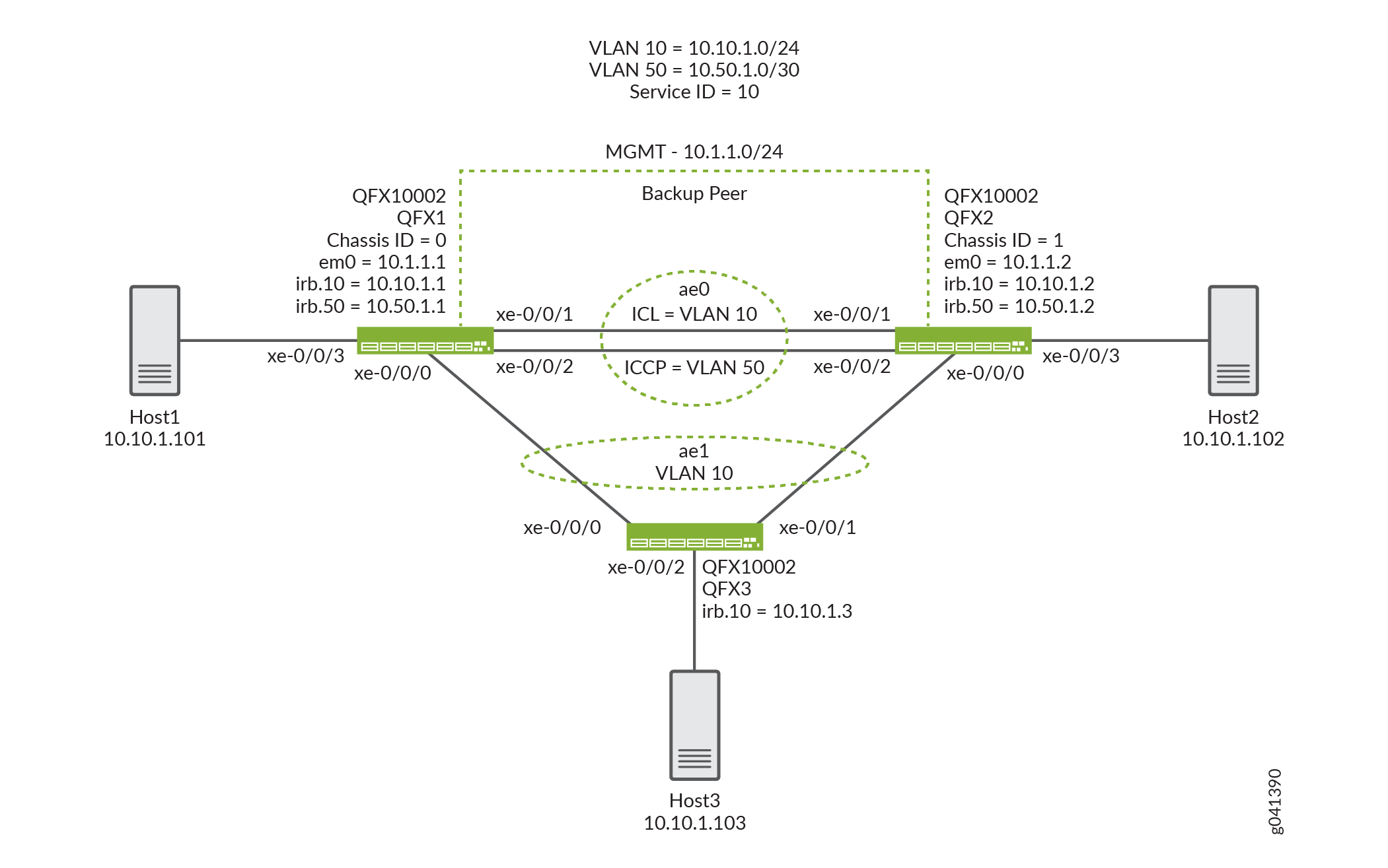
이 예에서 사용되는 토폴로지는 MC-LAG를 호스팅하는 두 개의 스위치로 구성됩니다. 두 스위치가 서버에 연결되어 있습니다. 그림 1 은 이 예에서 사용되는 토폴로지를 보여줍니다.
구성
CLI 빠른 구성
이 예를 빠르게 구성하려면, 아래 명령을 복사하여 텍스트 파일에 붙여 넣은 다음 모든 라인브레이크를 제거하고, 네트워크 구성을 일치하는 데 필요한 세부 사항을 변경하고, 계층 수준에서 [edit] 명령을 복사하여 CLI에 붙여 넣은 다음, 구성 모드에서 입력합니다 commit .
QFX1
set chassis aggregated-devices ethernet device-count 2
set interfaces xe-0/0/0 ether-options 802.3ad ae1
set interfaces xe-0/0/1 ether-options 802.3ad ae0
set interfaces xe-0/0/2 ether-options 802.3ad ae0
set interfaces xe-0/0/3 unit 0 family ethernet-switching interface-mode access
set interfaces xe-0/0/3 unit 0 family ethernet-switching vlan members v10
set interfaces ae0 aggregated-ether-options lacp active
set interfaces ae0 unit 0 family ethernet-switching interface-mode trunk
set interfaces ae0 unit 0 family ethernet-switching vlan members v50
set interfaces ae0 unit 0 family ethernet-switching vlan members v10
set interfaces ae1 aggregated-ether-options lacp active
set interfaces ae1 aggregated-ether-options lacp system-id 00:01:02:03:04:05
set interfaces ae1 aggregated-ether-options lacp admin-key 3
set interfaces ae1 aggregated-ether-options mc-ae mc-ae-id 3
set interfaces ae1 aggregated-ether-options mc-ae redundancy-group 1
set interfaces ae1 aggregated-ether-options mc-ae chassis-id 0
set interfaces ae1 aggregated-ether-options mc-ae mode active-active
set interfaces ae1 aggregated-ether-options mc-ae status-control active
set interfaces ae1 aggregated-ether-options mc-ae init-delay-time 240
set interfaces ae1 unit 0 family ethernet-switching interface-mode trunk
set interfaces ae1 unit 0 family ethernet-switching vlan members v10
set interfaces em0 unit 0 family inet address 10.1.1.1/24
set interfaces irb unit 10 family inet address 10.10.1.1/24
set interfaces irb unit 50 family inet address 10.50.1.1/30
set multi-chassis multi-chassis-protection 10.50.1.2 interface ae0
set protocols iccp local-ip-addr 10.50.1.1
set protocols iccp peer 10.50.1.2 session-establishment-hold-time 340
set protocols iccp peer 10.50.1.2 redundancy-group-id-list 1
set protocols iccp peer 10.50.1.2 backup-liveness-detection backup-peer-ip 10.1.1.2
set protocols iccp peer 10.50.1.2 liveness-detection minimum-receive-interval 1000
set protocols iccp peer 10.50.1.2 liveness-detection transmit-interval minimum-interval 1000
set switch-options service-id 10
set vlans v10 vlan-id 10
set vlans v10 l3-interface irb.10
set vlans v50 vlan-id 50
set vlans v50 l3-interface irb.50
QFX2
set chassis aggregated-devices ethernet device-count 2
set interfaces xe-0/0/0 ether-options 802.3ad ae1
set interfaces xe-0/0/1 ether-options 802.3ad ae0
set interfaces xe-0/0/2 ether-options 802.3ad ae0
set interfaces xe-0/0/3 unit 0 family ethernet-switching interface-mode access
set interfaces xe-0/0/3 unit 0 family ethernet-switching vlan members v10
set interfaces ae0 aggregated-ether-options lacp active
set interfaces ae0 unit 0 family ethernet-switching interface-mode trunk
set interfaces ae0 unit 0 family ethernet-switching vlan members v50
set interfaces ae0 unit 0 family ethernet-switching vlan members v10
set interfaces ae1 aggregated-ether-options lacp active
set interfaces ae1 aggregated-ether-options lacp system-id 00:01:02:03:04:05
set interfaces ae1 aggregated-ether-options lacp admin-key 3
set interfaces ae1 aggregated-ether-options mc-ae mc-ae-id 3
set interfaces ae1 aggregated-ether-options mc-ae redundancy-group 1
set interfaces ae1 aggregated-ether-options mc-ae chassis-id 1
set interfaces ae1 aggregated-ether-options mc-ae mode active-active
set interfaces ae1 aggregated-ether-options mc-ae status-control standby
set interfaces ae1 aggregated-ether-options mc-ae init-delay-time 240
set interfaces ae1 unit 0 family ethernet-switching interface-mode trunk
set interfaces ae1 unit 0 family ethernet-switching vlan members v10
set interfaces em0 unit 0 family inet address 10.1.1.2/24
set interfaces irb unit 10 family inet address 10.10.1.2/24
set interfaces irb unit 50 family inet address 10.50.1.2/30
set multi-chassis multi-chassis-protection 10.50.1.1 interface ae0
set protocols iccp local-ip-addr 10.50.1.2
set protocols iccp peer 10.50.1.1 session-establishment-hold-time 340
set protocols iccp peer 10.50.1.1 redundancy-group-id-list 1
set protocols iccp peer 10.50.1.1 backup-liveness-detection backup-peer-ip 10.1.1.1
set protocols iccp peer 10.50.1.1 liveness-detection minimum-receive-interval 1000
set protocols iccp peer 10.50.1.1 liveness-detection transmit-interval minimum-interval 1000
set switch-options service-id 10
set vlans v10 vlan-id 10
set vlans v10 l3-interface irb.10
set vlans v50 vlan-id 50
set vlans v50 l3-interface irb.50
QFX3
set chassis aggregated-devices ethernet device-count 2
set interfaces xe-0/0/0 ether-options 802.3ad ae1
set interfaces xe-0/0/1 ether-options 802.3ad ae1
set interfaces xe-0/0/2 unit 0 family ethernet-switching interface-mode access
set interfaces xe-0/0/2 unit 0 family ethernet-switching vlan members v10
set interfaces ae1 aggregated-ether-options lacp active
set interfaces ae1 unit 0 family ethernet-switching interface-mode trunk
set interfaces ae1 unit 0 family ethernet-switching vlan members v10
set interfaces em0 unit 0 family inet address 10.1.1.3/24
set interfaces irb unit 10 family inet address 10.10.1.3/24
set vlans v10 vlan-id 10
set vlans v10 l3-interface irb.10
두 개의 스위치에서 MC-LAG 구성
단계별 절차
다음 예에서는 구성 계층에서 다양한 수준을 탐색해야 합니다. CLI 탐색에 대한 정보는 구성 모드에서 CLI 편집기 사용을 참조하십시오.
MC-LAG 피어 간의 인터페이스 및 다중 섀시 보호 링크를 활성화하려면:
-
QFX1과 QFX2 모두에서 LAG 수를 구성합니다.
[edit chassis]
user@switch# set aggregated-devices ethernet device-count 2
-
QFX1 및 QFX2 모두에서 어그리게이션 이더넷 인터페이스에 멤버 인터페이스를 추가합니다.
QFX1 and QFX2:
[edit interfaces]
user@switch# set xe-0/0/0 ether-options 802.3ad ae1
[edit interfaces]
user@switch# set xe-0/0/1 ether-options 802.3ad ae0
[edit interfaces]
user@switch# set xe-0/0/2 ether-options 802.3ad ae0
-
연결된 최종 호스트에 대한 액세스 인터페이스를 구성합니다.
[edit interfaces]
user@switch# set xe-0/0/3 unit 0 family ethernet-switching interface-mode access
-
VLAN v10에 멤버 인터페이스를 추가합니다.
[edit interfaces]
user@switch# set interfaces xe-0/0/3 unit 0 family ethernet-switching vlan members v10
-
QFX1과 QFX2 간의 트렁크 인터페이스를 구성합니다.
[edit interfaces]
user@switch# set ae0 unit 0 family ethernet-switching interface-mode trunk
-
QFX1과 QFX2 사이의 MC-LAG에서 VLAN을 활성화합니다.
[edit]
user@switch# set vlans v10 vlan-id 10
>[edit]
user@switch# set vlans v50 vlan-id 50
>[edit interfaces]
user@switch# set ae0 unit 0 family ethernet-switching vlan members v10
>[edit interfaces]
user@switch# set ae0 unit 0 family ethernet-switching vlan members v50
-
IRB 50을 구성합니다.
>[edit irb]
user@switch# set irb.50
-
irb.50에 VLAN 50을 할당합니다.
>[edit]
user@switch# set vlans v50 l3-interface irb.50
-
IRB 10을 구성합니다.
>[edit irb]
user@switch# set irb.10
-
VLAN 10 irb.10을 할당합니다.
>[edit]
user@switch# set vlans v10 l3-interface irb.10
-
QFX1 및 QFX2의 MC-LAG 인터페이스에서 LACP를 활성화합니다.
참고:적어도 한쪽 끝이 활성화되어야 합니다. 다른 쪽 끝은 능동적이거나 수동적일 수 있습니다.
>[edit interfaces]
user@switch# set ae0 aggregated-ether-options lacp active

[edit interfaces]
user@switch# set ae1 aggregated-ether-options lacp active
-
QFX1 및 QFX2의 MC-LAG에 대해 동일한 LACP 시스템 ID를 지정합니다.
>[edit interfaces]
user@switch# set ae1 aggregated-ether-options lacp system-ID 00:01:02:03:04:05
-
QFX1과 QFX2 모두에 동일한 LACP 관리 키를 지정합니다.
>[edit interfaces]
user@switch# set ae1 aggregated-ether-options lacp admin-key 3
-
QFX1 및 QFX2의 MC-LAG 피어 모두에서 동일한 다중 섀시 어그리게이션 이더넷 식별 번호를 지정합니다.
>[edit interfaces]
user@switch# set ae1 aggregated-ether-options mc-ae mc-ae-id 3
-
QFX1 및 QFX2의 MC-LAG 피어에서 MC-LAG에 대한 고유한 섀시 ID를 지정합니다.
>QFX1:
[edit interfaces]
user@switch# set ae1 aggregated-ether-options mc-ae chassis-id 0
>QFX2:
[edit interfaces]
user@switch# set ae1 aggregated-ether-options mc-ae chassis-id 1
-
QFX1 및 QFX2 모두에서 MC-LAG의 작동 모드를 지정합니다.
참고:현재는 액티브-액티브 모드만 지원됩니다.
>[edit interfaces]
user@switch# set ae1 aggregated-ether-options mc-ae mode active-active
-
QFX1 및 QFX2에서 MC-LAG에 대한 상태 제어를 지정합니다.
참고:MC-LAG를 호스팅하는 QFX1과 QFX2 모두에서 상태 제어를 구성해야 합니다. 하나의 피어가 활성 모드에 있으면 다른 피어는 대기 모드에 있어야 합니다.
>QFX1:
[edit interfaces]
user@switch# set ae1 aggregated-ether-options mc-ae status-control active
>QFX2:
[edit interfaces]
user@switch# set ae1 aggregated-ether-options mc-ae status-control standby
-
QFX1 및 QFX2를 재부팅한 후 다중 섀시 어그리게이션 이더넷 인터페이스의 가동이 지연되는 시간(초)을 지정합니다.
참고:최대 VLAN 구성(예: 4,000 VLAN)에 대한 권장 값은 240초입니다. 모든 VLAN에서 IGMP 스누핑이 활성화된 경우 권장 값은 420초입니다.
>[edit interfaces]
user@switch# set ae1 aggregated-ether-options mc-ae init-delay-time 240
-
QFX1과 QFX2 모두에서 MC-LAG 피어 간 레이어 3 연결을 구성합니다.
>[edit vlans]
user@switch# set v50 vlan-id 50
>[edit vlans]
user@switch# set v50 l3-interface irb.50
>[edit interfaces]
user@switch# set ae0 unit 0 family ethernet-switching interface-mode trunk vlan members v50
-
QFX1과 QFX2 간에 다중 섀시 보호 링크를 구성합니다.
>QFX1:
[edit]
user@switch# set multi-chassis multi-chassis-protection 10.50.1.2 interface ae0
>QFX2:
[edit]
user@switch# set multi-chassis multi-chassis-protection 10.50.1.1 interface ae0
-
QFX1 및 QFX2의 ICCP 연결에 로컬 IP 주소를 구성합니다.
>QFX1:
[edit protocols]
user@switch# set iccp local-ip-addr 10.50.1.1
>QFX2:
[edit protocols]
user@switch# set iccp local-ip-addr 10.50.1.2
-
(선택 사항) QFX1과 QFX2의 MC-LAG 피어 간에 ICCP 연결이 성공해야 하는 시간을 구성합니다.
참고:QFX 시리즈 스위치에서 기본 세션 설정 보류 시간은 300초입니다. 그러나 세션 설정 시간은 초기화 지연 시간보다 최소 100초 더 빨라야 합니다. 선택적으로 세션 설정 시간을 340초로 업데이트하고 초기화 지연 시간을 240초로 업데이트할 수 있습니다.
>QFX1:
[edit protocols]
user@switch# set iccp peer 10.50.1.2 session-establishment-hold-time 340
>QFX2:
[edit protocols]
user@switch# set iccp peer 10.50.1.1 session-establishment-hold-time 340
-
QFX1 및 QFX2에서 ICCP에 대한 중복 그룹을 구성합니다.
>QFX1:
[edit protocols]
user@switch# set iccp peer 10.50.1.2 redundancy-group-id-list 1
>QFX2:
[edit protocols]
user@switch# set iccp peer 10.50.1.1 redundancy-group-id-list 1
-
(선택 사항) QFX1 및 QFX2 모두에서 백업 활성 감지에 사용할 백업 IP 주소를 구성합니다.
참고:기본적으로 백업 활성 감지는 활성화되지 않습니다. 백업 IP 주소를 구성하면 MC-LAG 피어 재부팅 중에 1초 미만의 트래픽 손실을 달성하는 데 도움이 됩니다.
>QFX1:
[edit protocols]
user@switch# set iccp peer 10.50.1.2 backup-liveness-detection backup-peer-ip 10.1.1.2
>QFX2:
[edit protocols]
user@switch# set iccp peer 10.50.1.1 backup-liveness-detection backup-peer-ip 10.1.1.1
-
QFX1 및 QFX2에서 ICCP에 대한 BFD 세션에 대한 피어 IP 주소 및 최소 수신 간격을 구성합니다.
>QFX1:
[edit protocols]
user@switch# set iccp peer 10.50.1.2 liveness-detection minimum-receive-interval 1000
>QFX2:
[edit protocols]
user@switch# set iccp peer 10.50.1.1 liveness-detection minimum-receive-interval 1000
-
QFX1 및 QFX2에서 ICCP에 대한 BFD 세션의 피어 IP 주소 및 최소 전송 간격을 구성합니다.
>QFX1:
[edit protocols]
user@switch# set iccp peer 10.50.1.2 liveness-detection transmit-interval minimum-interval 1000
>QFX2:
[edit protocols]
user@switch# set iccp peer 10.50.1.1 liveness-detection transmit-interval minimum-interval 1000
-
QFX1 및 QFX2에서 서비스 ID를 활성화하려면:
스위치 서비스 ID는 MC-LAG 멤버 간에 애플리케이션, IGMP, ARP 및 MAC 학습을 동기화하는 데 사용됩니다.
>[edit switch-options]
user@switch# set service-id 10
결과
다음은 QFX1에서 구성한 결과입니다.
chassis {
    aggregated-devices {
        ethernet {
            device-count 2;
        }
    }
}
interfaces {
    xe-0/0/0 {
        ether-options {
            802.3ad ae1;
        }
    }
    xe-0/0/1 {
        ether-options {
            802.3ad ae0;
        }
    }
    xe-0/0/2 {
        ether-options {
            802.3ad ae0;
        }
    }
    xe-0/0/3 {
        unit 0 {
            family ethernet-switching {
                interface-mode access;
                vlan {
                    members v10;
                }
            }
        }
    }
    ae0 {
        aggregated-ether-options {
            lacp {
                active;
            }
        }
        unit 0 {
            family ethernet-switching {
                interface-mode trunk;
                vlan {
                    members [ v50 v10 ];
                }
            }
        }
    }
    ae1 {
        aggregated-ether-options {
            lacp {
                active;
                system-id 00:01:02:03:04:05;
                admin-key 3;
            }
            mc-ae {
                mc-ae-id 3;
                redundancy-group 1;
                chassis-id 0;
                mode active-active;
                status-control active;
                init-delay-time 240;
            }
        }
        unit 0 {
            family ethernet-switching {
                interface-mode trunk;
                vlan {
                    members v10;
                }
            }
        }
    }
    em0 {
        unit 0 {
            family inet {
                address 10.1.1.1/24;
            }
        }
    }
    irb {
        unit 10 {
            family inet {
                address 10.10.1.1/24;
            }
        }
        unit 50 {
            family inet {
                address 10.50.1.1/30;
            }
        }
    }
}
multi-chassis {
    multi-chassis-protection 10.50.1.2 {
        interface ae0;
    }
}
protocols {
    iccp {
        local-ip-addr 10.50.1.1;
        peer 10.50.1.2 {
            session-establishment-hold-time 340;
            redundancy-group-id-list 1;
            backup-liveness-detection {
                backup-peer-ip 10.1.1.2;
            }
            liveness-detection {
                minimum-receive-interval 1000;
                transmit-interval {
                    minimum-interval 1000;
                }
            }
        }
    }
}
switch-options {
    service-id 10;
}
vlans {
    v10 {
        vlan-id 10;
        l3-interface irb.10;
    }
    v50 {
        vlan-id 50;
        l3-interface irb.50;
    }
}
QFX2에 구성 결과를 표시합니다.
chassis {
    aggregated-devices {
        ethernet {
            device-count 2;
        }
    }
}
interfaces {
    xe-0/0/0 {
        ether-options {
            802.3ad ae1;
        }
    }
    xe-0/0/1 {
        ether-options {
            802.3ad ae0;
        }
    }
    xe-0/0/2 {
        ether-options {
            802.3ad ae0;
        }
    }
    xe-0/0/3 {
        unit 0 {
            family ethernet-switching {
                interface-mode access;
                vlan {
                    members v10;
                }
            }
        }
    }
    ae0 {
        aggregated-ether-options {
            lacp {
                active;
            }
        }
        unit 0 {
            family ethernet-switching {
                interface-mode trunk;
                vlan {
                    members [ v50 v10 ];
                }
            }
        }
    }
    ae1 {
        aggregated-ether-options {
            lacp {
                active;
                system-id 00:01:02:03:04:05;
                admin-key 3;
            }
            mc-ae {
                mc-ae-id 3;
                redundancy-group 1;
                chassis-id 1;
                mode active-active;
                status-control standby;
                init-delay-time 240;
            }
        }
        unit 0 {
            family ethernet-switching {
                interface-mode trunk;
                vlan {
                    members v10;
                }
            }
        }
    }
    em0 {
        unit 0 {
            family inet {
                address 10.1.1.2/24;
            }
        }
    }
    irb {
        unit 10 {
            family inet {
                address 10.10.1.2/24;
            }
        }
        unit 50 {
            family inet {
                address 10.50.1.2/30;
            }
        }
    }
}
multi-chassis {
    multi-chassis-protection 10.50.1.1 {
        interface ae0;
    }
}
protocols {
    iccp {
        local-ip-addr 10.50.1.2;
        peer 10.50.1.1 {
            session-establishment-hold-time 340;
            redundancy-group-id-list 1;
            backup-liveness-detection {
                backup-peer-ip 10.1.1.1;
            }
            liveness-detection {
                minimum-receive-interval 1000;
                transmit-interval {
                    minimum-interval 1000;
                }
            }
        }
    }
}
switch-options {
    service-id 10;
}
vlans {
    v10 {
        vlan-id 10;
        l3-interface irb.10;
    }
    v50 {
        vlan-id 50;
        l3-interface irb.50;
    }
}
QFX3에 구성 결과를 표시합니다.
chassis {
    aggregated-devices {
        ethernet {
            device-count 2;
        }
    }
}
interfaces {
    xe-0/0/0 {
        ether-options {
            802.3ad ae1;
        }
    }
    xe-0/0/1 {
        ether-options {
            802.3ad ae1;
        }
    }
    xe-0/0/2 {
        unit 0 {
            family ethernet-switching {
                interface-mode access;
                vlan {
                    members v10;
                }
            }
        }
    }
    ae1 {
        aggregated-ether-options {
            lacp {
                active;
            }
        }
        unit 0 {
            family ethernet-switching {
                interface-mode trunk;
                vlan {
                    members v10;
                }
            }
        }
    }
    em0 {
        unit 0 {
            family inet {
                address 10.1.1.3/24;
            }
        }
    }
    irb {
        unit 10 {
            family inet {
                address 10.10.1.3/24;
            }
        }
    }
}
vlans {
    v10 {
        vlan-id 10;
        l3-interface irb.10;
    }
}
검증
구성이 제대로 작동하고 있는지 확인합니다.
- ICCP가 QFX1에서 작동하는지 확인
- QFX1에서 LACP가 활성화되는지 확인
- QFX1에서 MC-AE 및 ICL-PL 인터페이스가 작동하는지 확인
- QFX1에서 MAC 학습이 발생하는지 확인
- Host1이 Host2에 연결할 수 있는지 확인
ICCP가 QFX1에서 작동하는지 확인
목적
ICCP가 QFX1에서 실행되고 있는지 확인합니다.
작업
user@switch> show iccp
Redundancy Group Information for peer 10.50.1.2
  TCP Connection       : Established
  Liveliness Detection : Up
  Backup liveness peer status: Up
  Redundancy Group ID          Status
    1                           Up

Client Application: lacpd
  Redundancy Group IDs Joined: 1

Client Application: l2ald_iccpd_client
  Redundancy Group IDs Joined: 1
의미
이 출력은 MC-LAG를 호스팅하는 피어 간의 TCP 연결이 작동 중이고, 활성 감지가 작동하며, MCSNOOPD 및 ESWD 클라이언트 애플리케이션이 실행 중임을 보여줍니다.
QFX1에서 LACP가 활성화되는지 확인
목적
LACP가 QFX1에서 활성화되는지 확인합니다.
작업
user@switch> show lacp interfaces
Aggregated interface: ae0
    LACP state:       Role   Exp   Def  Dist  Col  Syn  Aggr  Timeout  Activity
      xe-0/0/1       Actor    No    No   Yes  Yes  Yes   Yes     Fast    Active
      xe-0/0/1     Partner    No    No   Yes  Yes  Yes   Yes     Fast    Active
      xe-0/0/2       Actor    No    No   Yes  Yes  Yes   Yes     Fast    Active
      xe-0/0/2     Partner    No    No   Yes  Yes  Yes   Yes     Fast    Active
    LACP protocol:        Receive State  Transmit State          Mux State
      xe-0/0/1                  Current   Fast periodic Collecting distributing
      xe-0/0/2                  Current   Fast periodic Collecting distributing

Aggregated interface: ae1
    LACP state:       Role   Exp   Def  Dist  Col  Syn  Aggr  Timeout  Activity
      xe-0/0/0       Actor    No    No   Yes  Yes  Yes   Yes     Fast    Active
      xe-0/0/0     Partner    No    No   Yes  Yes  Yes   Yes     Fast    Active
    LACP protocol:        Receive State  Transmit State          Mux State
      xe-0/0/0                  Current   Fast periodic Collecting distributing
의미
이 출력은 QFX1이 LACP 협상에 참여하고 있음을 보여줍니다.
QFX1에서 MC-AE 및 ICL-PL 인터페이스가 작동하는지 확인
목적
MC-AE 및 ICL-PL 인터페이스가 QFX1에서 작동 중인지 확인합니다.
작업
user@switch> show interfaces mc-ae
 Member Link                  : ae1
 Current State Machine's State: mcae active state
 Local Status                 : active
 Local State                  : up
 Peer Status                  : active
 Peer State                   : up
     Logical Interface        : ae1.0
     Topology Type            : bridge
     Local State              : up
     Peer State               : up
     Peer Ip/MCP/State        : 10.50.1.2 ae0.0 up
의미
이 출력은 QFX1의 MC-AE 인터페이스가 작동 중이고 활성 상태임을 보여줍니다.
QFX1에서 MAC 학습이 발생하는지 확인
목적
MAC 학습이 QFX1에서 작동하는지 확인합니다.
작업
user@switch> show ethernet-switching table
MAC flags (S - static MAC, D - dynamic MAC, L - locally learned, P - Persistent static, C - Control MAC
           SE - statistics enabled, NM - non configured MAC, R - remote PE MAC, O - ovsdb MAC)


Ethernet switching table : 3 entries, 3 learned
Routing instance : default-switch
    Vlan                MAC                 MAC         Age    Logical                NH        RTR
    name                address             flags              interface              Index     ID
    v10                 00:50:56:93:73:cd   DR            -   ae0.0                  0         0
    v10                 00:50:56:93:87:58   DL            -   xe-0/0/3.0             0         0
    v10                 00:50:56:93:89:a0   DLR           -   ae1.0                  0         0
의미
출력에는 학습된 MAC 주소 항목 3개가 표시됩니다.
Host1이 Host2에 연결할 수 있는지 확인
목적
Host1이 Host2를 ping할 수 있는지 확인합니다.
작업
[edit]
user@HOST1> ping 10.10.1.102
PING 10.10.1.102 (10.10.1.102): 56 data bytes
64 bytes from 10.10.1.102: icmp_seq=0 ttl=64 time=157.788 ms
64 bytes from 10.10.1.102: icmp_seq=1 ttl=64 time=153.965 ms
64 bytes from 10.10.1.102: icmp_seq=2 ttl=64 time=102.126 ms
...
의미
출력은 HOST1이 HOST2를 성공적으로 ping할 수 있음을 보여줍니다.
예: MX 시리즈에서 멀티섀시 링크 어그리게이션 구성
이 예는 PE에서 트래픽을 로드 밸런싱하는 액티브-액티브 시나리오에서 멀티섀시 링크 어그리게이션 그룹(MC-LAG)을 구성하는 방법을 보여줍니다.
요구 사항
이 예에서 사용되는 하드웨어 및 소프트웨어 구성 요소는 다음과 같습니다.
이 예는 QFX10002 및 QFX10008 스위치에도 적용됩니다.
-
주니퍼 네트웍스 MX 시리즈 라우터 4개(MX240, MX480, MX960)
-
4개의 라우터 모두에서 실행되는 Junos OS 릴리스 11.2 이상
개요
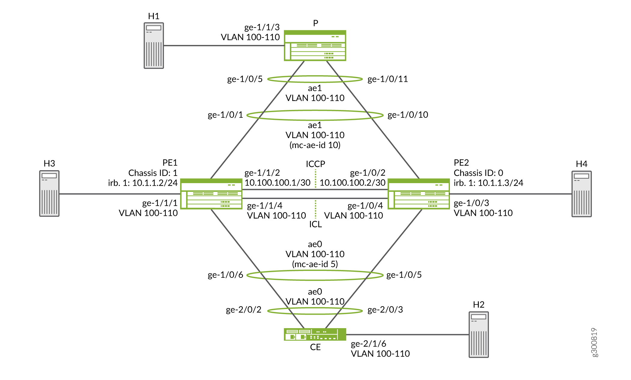
고객 에지 라우터 CE가 각각 두 개의 프로바이더 에지(PE) 라우터인 PE1과 PE2에 연결된 샘플 토폴로지를 생각해 보십시오. 두 개의 PE 디바이스는 각각 CE 디바이스에 연결된 링크 어그리게이션 그룹(LAG)을 가지고 있습니다. 구성된 모드는 active-active이며, 이는 두 PE 라우터의 LAG 포트가 활성 상태이고 동시에 트래픽을 전달한다는 것을 의미합니다. PE1과 PE2는 단일 서비스 프로바이더 라우터 P에 연결됩니다.
이 예에서 CE 라우터는 어그리게이션 이더넷 링크가 두 개의 개별 PE 디바이스에 연결되어 있다는 사실을 인식하지 못합니다. 두 개의 PE 디바이스는 각각 CE 디바이스에 연결된 LAG를 가지고 있습니다. 구성된 모드는 액티브-액티브이며, 이는 두 PE 라우터의 LAG 포트가 동시에 활성 상태이고 트래픽을 전달한다는 것을 의미합니다.
라우터 CE의 관점에서 그림 2에서 LAG에 속하는 4개의 포트가 모두 단일 서비스 프로바이더 디바이스에 연결되어 있습니다. 구성된 모드가 액티브-액티브이기 때문에 4개의 포트가 모두 활성이며 CE 디바이스는 피어링 PE 디바이스에 트래픽을 로드 밸런싱합니다. PE 라우터에서는 정규 LAG가 CE 디바이스를 향하여 구성됩니다.
MC-LAG의 한쪽 끝에는 LAG에 하나 이상의 물리적 링크가 있는 서버와 같은 MC-LAG 클라이언트 디바이스가 있습니다. 이 클라이언트 디바이스는 MC-LAG를 감지할 필요가 없습니다. MC-LAG의 반대편에는 두 개의 MC-LAG 라우터가 있습니다. 각 라우터에는 단일 클라이언트 디바이스에 연결된 하나 이상의 물리적 링크가 있습니다. 라우터는 데이터 트래픽이 제대로 전달되도록 서로 협력합니다.
ICCP 메시지는 두 PE 디바이스 간에 전송됩니다. 이 예에서는 두 개의 어그리게이션 이더넷 인터페이스, 섀시 간 링크 보호 링크(ICL-PL), ICL-PL을 위한 멀티섀시 보호 링크 및 MC-LAG를 호스팅하는 피어를 위한 ICCP로 구성된 두 개의 라우터에 걸쳐 MC-LAG를 구성합니다.
PE 라우터 구성
CLI 빠른 구성
이 예를 빠르게 구성하려면, 아래 명령을 복사하여 텍스트 파일에 붙여 넣은 다음 모든 라인브레이크를 제거하고, 네트워크 구성을 일치하는 데 필요한 세부 사항을 변경하고, 계층 수준에서 [edit] 명령을 복사하여 CLI에 붙여 넣은 다음, 구성 모드에서 입력합니다 commit .
라우터 PE1
set chassis aggregated-devices ethernet device-count 5
set interfaces ge-1/0/1 gigether-options 802.3ad ae1
set interfaces ge-1/1/2 unit 0 family inet address 10.100.100.1/30
set interfaces ge-1/0/6 gigether-options 802.3ad ae0
set interfaces ge-1/1/1 flexible-vlan-tagging
set interfaces ge-1/1/1 encapsulation flexible-ethernet-services
set interfaces ge-1/1/1 unit 0 encapsulation vlan-bridge
set interfaces ge-1/1/1 unit 0 vlan-id-range 100-110
set interfaces ge-1/1/4 flexible-vlan-tagging
set interfaces ge-1/1/4 encapsulation flexible-ethernet-services
set interfaces ge-1/1/4 unit 0 encapsulation vlan-bridge
set interfaces ge-1/1/4 unit 0 vlan-id-range 100-110
set interfaces ae0 flexible-vlan-tagging
set interfaces ae0 encapsulation flexible-ethernet-services
set interfaces ae0 aggregated-ether-options lacp active
set interfaces ae0 aggregated-ether-options lacp system-priority 100
set interfaces ae0 aggregated-ether-options lacp system-id 00:00:00:00:00:05
set interfaces ae0 aggregated-ether-options lacp admin-key 1
set interfaces ae0 aggregated-ether-options mc-ae mc-ae-id 5
set interfaces ae0 aggregated-ether-options mc-ae redundancy-group 10
set interfaces ae0 aggregated-ether-options mc-ae chassis-id 1
set interfaces ae0 aggregated-ether-options mc-ae mode active-active
set interfaces ae0 aggregated-ether-options mc-ae status-control active
set interfaces ae0 unit 0 encapsulation vlan-bridge
set interfaces ae0 unit 0 vlan-id-range 100-110
set interfaces ae0 unit 0 multi-chassis-protection 10.100.100.2 interface ge-1/1/4.0
set interfaces ae1 flexible-vlan-tagging
set interfaces ae1 encapsulation flexible-ethernet-services
set interfaces ae1 aggregated-ether-options lacp active
set interfaces ae1 aggregated-ether-options lacp system-priority 100
set interfaces ae1 aggregated-ether-options lacp system-id 00:00:00:00:00:05
set interfaces ae1 aggregated-ether-options lacp admin-key 1
set interfaces ae1 aggregated-ether-options mc-ae mc-ae-id 10
set interfaces ae1 aggregated-ether-options mc-ae redundancy-group 10
set interfaces ae1 aggregated-ether-options mc-ae chassis-id 1
set interfaces ae1 aggregated-ether-options mc-ae mode active-active
set interfaces ae1 aggregated-ether-options mc-ae status-control active
set interfaces ae1 unit 0 encapsulation vlan-bridge
set interfaces ae1 unit 0 vlan-id-range 100-110
set interfaces ae1 unit 0 multi-chassis-protection 10.100.100.2 interface ge-1/1/4.0
set bridge-domains bd0 domain-type bridge
set bridge-domains bd0 vlan-id all
set bridge-domains bd0 service-id 20
set bridge-domains bd0 interface ae1.0
set bridge-domains bd0 interface ge-1/0/3.0
set bridge-domains bd0 interface ge-1/1/1.0
set bridge-domains bd0 interface ge-1/1/4.0
set bridge-domains bd0 interface ae0.0
set protocols iccp local-ip-addr 10.100.100.1
set protocols iccp peer 10.100.100.2 redundancy-group-id-list 10
set protocols iccp peer 10.100.100.2 liveness-detection minimum-interval 1000
set switch-options service-id 10
라우터 PE2
set chassis aggregated-devices ethernet device-count 5
set interfaces ge-1/0/2 unit 0 family inet address 10.100.100.2/30
set interfaces ge-1/0/3 flexible-vlan-tagging
set interfaces ge-1/0/3 encapsulation flexible-ethernet-services
set interfaces ge-1/0/3 unit 0 encapsulation vlan-bridge
set interfaces ge-1/0/3 unit 0 vlan-id-range 100-110
set interfaces ge-1/0/4 flexible-vlan-tagging
set interfaces ge-1/0/4 encapsulation flexible-ethernet-services
set interfaces ge-1/0/4 unit 0 encapsulation vlan-bridge
set interfaces ge-1/0/4 unit 0 vlan-id-range 100-110
set interfaces ge-1/0/5 gigether-options 802.3ad ae0
set interfaces ge-1/1/0 gigether-options 802.3ad ae1
set interfaces ae0 flexible-vlan-tagging
set interfaces ae0 encapsulation flexible-ethernet-services
set interfaces ae0 aggregated-ether-options lacp active
set interfaces ae0 aggregated-ether-options lacp system-priority 100
set interfaces ae0 aggregated-ether-options lacp system-id 00:00:00:00:00:05
set interfaces ae0 aggregated-ether-options lacp admin-key 1
set interfaces ae0 aggregated-ether-options mc-ae mc-ae-id 5
set interfaces ae0 aggregated-ether-options mc-ae redundancy-group 10
set interfaces ae0 aggregated-ether-options mc-ae chassis-id 0
set interfaces ae0 aggregated-ether-options mc-ae mode active-active
set interfaces ae0 aggregated-ether-options mc-ae status-control standby
set interfaces ae0 unit 0 encapsulation vlan-bridge
set interfaces ae0 unit 0 vlan-id-range 100-110
set interfaces ae0 unit 0 multi-chassis-protection 10.100.100.1 interface ge-1/0/4.0
set interfaces ae1 flexible-vlan-tagging
set interfaces ae1 encapsulation flexible-ethernet-services
set interfaces ae1 aggregated-ether-options lacp active
set interfaces ae1 aggregated-ether-options lacp system-priority 100
set interfaces ae1 aggregated-ether-options lacp system-id 00:00:00:00:00:05
set interfaces ae1 aggregated-ether-options lacp admin-key 1
set interfaces ae1 aggregated-ether-options mc-ae mc-ae-id 10
set interfaces ae1 aggregated-ether-options mc-ae redundancy-group 10
set interfaces ae1 aggregated-ether-options mc-ae chassis-id 0
set interfaces ae1 aggregated-ether-options mc-ae mode active-active
set interfaces ae1 aggregated-ether-options mc-ae status-control standby
set interfaces ae1 unit 0 encapsulation vlan-bridge
set interfaces ae1 unit 0 vlan-id-range 100-110
set interfaces ae1 unit 0 multi-chassis-protection 10.100.100.1 interface ge-1/0/4.0
set bridge-domains bd0 domain-type bridge
set bridge-domains bd0 vlan-id all
set bridge-domains bd0 service-id 20
set bridge-domains bd0 interface ae1.0
set bridge-domains bd0 interface ge-1/0/3.0
set bridge-domains bd0 interface ge-1/0/4.0
set bridge-domains bd0 interface ae0.0
set protocols iccp local-ip-addr 10.100.100.2
set protocols iccp peer 10.100.100.1 redundancy-group-id-list 10
set protocols iccp peer 10.100.100.1 liveness-detection minimum-interval 1000
set switch-options service-id 10
PE1 라우터 구성
단계별 절차
다음 예에서는 구성 계층에서 다양한 수준을 탐색해야 합니다. CLI 탐색에 대한 정보는 구성 모드에서 CLI 편집기 사용을 참조하십시오.
라우터 PE1을 구성하려면 다음을 수행합니다.
-
생성할 어그리게이션 이더넷 인터페이스의 수를 지정합니다.
[edit chassis]
user@PE1# set aggregated-devices ethernet device-count 5
-
어그리게이션 이더넷 번들에 포함될 멤버를 지정합니다.
[edit interfaces]
user@PE1# set ge-1/0/1 gigether-options 802.3ad ae1
user@PE1# set ge-1/0/6 gigether-options 802.3ad ae0
-
발신자 또는 수신자, ICL 인터페이스 및 ICCP 인터페이스에 연결하는 인터페이스를 구성합니다.
[edit interfaces]
user@PE1# set ge-1/1/1 flexible-vlan-tagging
user@PE1# set ge-1/1/1 encapsulation flexible-ethernet-services
user@PE1# set ge-1/1/1 unit 0 encapsulation vlan-bridge
user@PE1# set ge-1/1/1 unit 0 vlan-id-range 100-110

user@PE1# set ge-1/1/4 flexible-vlan-tagging
user@PE1# set ge-1/1/4 encapsulation flexible-ethernet-services
user@PE1# set ge-1/1/4 unit 0 encapsulation vlan-bridge
user@PE1# set ge-1/1/4 unit 0 vlan-id-range 100-110

user@PE1# set ge-1/1/2 unit 0 family inet address 10.100.100.1/30
-
어그리게이션 이더넷 번들에 매개 변수를 구성합니다.
[edit interfaces ae0]
user@PE1# set flexible-vlan-tagging
user@PE1# set encapsulation flexible-ethernet-services
user@PE1# set unit 0 encapsulation vlan-bridge
user@PE1# set unit 0 vlan-id-range 100-110
user@PE1# set unit 0 multi-chassis-protection 10.100.100.2 interface ge-1/1/4.0
[edit interfaces ae1]
user@PE1# set flexible-vlan-tagging
user@PE1# set encapsulation flexible-ethernet-services
user@PE1# set unit 0 encapsulation vlan-bridge
user@PE1# set unit 0 vlan-id-range 100-110
user@PE1# set unit 0 multi-chassis-protection 10.100.100.2 interface ge-1/1/4.0
-
어그리게이션 이더넷 번들에 LACP를 구성합니다.
[edit interfaces ae0 aggregated-ether-options]
user@PE1# set lacp active
user@PE1# set lacp system-priority 100
user@PE1# set lacp system-id 00:00:00:00:00:05
user@PE1# set lacp admin-key 1
[edit interfaces ae1 aggregated-ether-options]
user@PE1# set lacp active
user@PE1# set lacp system-priority 100
user@PE1# set lacp system-id 00:00:00:00:00:05
user@PE1# set lacp admin-key 1
-
MC-LAG 인터페이스를 구성합니다.
[edit interfaces ae0 aggregated-ether-options]
user@PE1# set mc-ae mc-ae-id 5
user@PE1# set mc-ae redundancy-group 10
user@PE1# set mc-ae chassis-id 1
user@PE1# set mc-ae mode active-active
user@PE1# set mc-ae status-control active
[edit interfaces ae1 aggregated-ether-options]
user@PE1# set mc-ae mc-ae-id 10
user@PE1# set mc-ae redundancy-group 10
user@PE1# set mc-ae chassis-id 1
user@PE1# set mc-ae mode active-active
user@PE1# set mc-ae status-control active
다중 섀시 어그리게이션 이더넷 식별 번호(mc-ae-id)는 어그리게이션 이더넷 인터페이스가 속하는 링크 어그리게이션 그룹을 지정합니다. 라우터 PE1 및 라우터 PE2의 ae0 인터페이스는 mc-ae-id 5로 구성됩니다. 라우터 PE1 및 라우터 PE2의 ae1 인터페이스는 mc-ae-id 10으로 구성됩니다.
redundancy-group 10이 문은 ICCP에서 유사한 중복 기능을 수행하는 여러 섀시를 연결하고 피어링 섀시의 애플리케이션이 서로 메시지를 보낼 수 있도록 통신 채널을 설정하는 데 사용됩니다. 라우터 PE1과 라우터 PE2의 ae0 및 ae1 인터페이스는 동일한 중복 그룹인 중복 그룹 10으로 구성됩니다.이
chassis-id문은 LACP에서 MC-LAG의 물리적 멤버 링크의 포트 번호를 계산하는 데 사용됩니다. 라우터 PE1은 chassid-id 1 을 사용하여 ae0 및 ae1 인터페이스를 모두 식별합니다. 라우터 PE2는 chassis-id 0 을 사용하여 ae0 및 ae1 인터페이스를 모두 식별합니다.이 문은
modeMC-LAG가 액티브-스탠바이 모드 또는 액티브-액티브 모드에 있는지 여부를 나타냅니다. 동일한 그룹에 있는 섀시는 동일한 모드에 있어야 합니다. -
논리적 포트 집합을 포함하는 도메인을 구성합니다.
[edit bridge-domains bd0]
user@PE1# set domain-type bridge
user@PE1# set vlan-id all
user@PE1# set service-id 20
user@PE1# set interface ae0.0
user@PE1# set interface ae1.0
user@PE1# set interface ge-1/1/1.0
user@PE1# set interface ge-1/1/4.0
브리지 도메인 내의 포트는 레이어 2 브리징을 수행하기 위해 동일한 플러딩 또는 브로드캐스트 특성을 공유합니다.
bridge-level
service-id문은 피어(이 경우 라우터 PE1 및 라우터 PE2) 간에 관련 브리지 도메인을 링크하는 데 필요하며 동일한 값으로 구성해야 합니다. -
ICCP 매개 변수를 구성합니다.
[edit protocols iccp]
user@PE1# set local-ip-addr 10.100.100.1
user@PE1# set peer 10.100.100.2 redundancy-group-id-list 10
user@PE1# set peer 10.100.100.2 liveness-detection minimum-interval 1000
-
글로벌 수준에서 서비스 ID를 구성합니다.
[edit switch-options]
user@PE1# set service-id 10
서비스를 제공하는 PE 라우터 집합에서 서비스에 대해 동일한 고유한 네트워크 전체 구성을 구성해야 합니다. 이 서비스 ID는 다중 섀시 어그리게이션 이더넷 인터페이스가 브리지 도메인의 일부인 경우에 필요합니다.
결과
구성 모드에서 , show chassis, show interfaces, show protocols및 show switch-options 명령을 show bridge-domains입력하여 구성을 확인합니다. 출력에 의도한 구성이 표시되지 않으면 이 예의 지침을 반복하여 구성을 수정합니다.
user@PE1#  show bridge-domains
bd0 {
    domain-type bridge;
    vlan-id all;
    service-id 20;
    interface ae1.0;
    interface ge-1/1/1.0;
    interface ge-1/1/4.0;
    interface ae0.0;
}
user@PE1#  show chassis
aggregated-devices {
    ethernet {
        device-count 5;
    }
}
user@PE1#  show interfaces
ge-1/0/1 {
    gigether-options {
        802.3ad ae1;
    }
}
ge-1/0/6 {
    gigether-options {
        802.3ad ae0;
    }
}
ge-1/1/2 {
    unit 0 {
        family inet {
            address 10.100.100.1/30;
        }
    }
}
ge-1/1/1 {
    flexible-vlan-tagging;
    encapsulation flexible-ethernet-services;
    unit 0 {
        encapsulation vlan-bridge;
        vlan-id-range 100-110;
    }
}
ge-1/1/4 {
    flexible-vlan-tagging;
    encapsulation flexible-ethernet-services;
    unit 0 {
        encapsulation vlan-bridge;
        vlan-id-range 100-110;
    }
}
ae0 {
    flexible-vlan-tagging;
    encapsulation flexible-ethernet-services;
    aggregated-ether-options {
        lacp {
            active;
            system-priority 100;
            system-id 00:00:00:00:00:05;
            admin-key 1;
        }
        mc-ae {
            mc-ae-id 5;
            redundancy-group 10;
            chassis-id 1;
            mode active-active;
            status-control active;
        }
    }
    unit 0 {
        encapsulation vlan-bridge;
        vlan-id-range 100-110;
        multi-chassis-protection 10.100.100.2 {
            interface ge-1/1/4.0;
        }
    }
}
ae1 {
    flexible-vlan-tagging;
    encapsulation flexible-ethernet-services;
    aggregated-ether-options {
        lacp {
            active;
            system-priority 100;
            system-id 00:00:00:00:00:05;
            admin-key 1;
        }
        mc-ae {
            mc-ae-id 10;
            redundancy-group 10;
            chassis-id 1;
            mode active-active;
            status-control active;
        }
    }
    unit 0 {
        encapsulation vlan-bridge;
        vlan-id-range 100-110;
        multi-chassis-protection 10.100.100.2 {
            interface ge-1/1/4.0;
        }
    }
}
user@PE1#  show protocols
iccp {
    local-ip-addr 10.100.100.1;
    peer 10.100.100.2 {
        redundancy-group-id-list 10;
        liveness-detection {
            minimum-interval 1000;
        }
    }
}
user@PE1#  show switch-options
service-id 10;
디바이스 구성이 완료되면 구성 모드에서 commit 을 입력합니다.
적절한 인터페이스 이름과 주소를 사용하여 라우터 PE2에 대한 절차를 반복합니다.
CE 디바이스 구성
CLI 빠른 구성
이 예를 빠르게 구성하려면, 아래 명령을 복사하여 텍스트 파일에 붙여 넣은 다음 모든 라인브레이크를 제거하고, 네트워크 구성을 일치하는 데 필요한 세부 사항을 변경하고, 계층 수준에서 [edit] 명령을 복사하여 CLI에 붙여 넣은 다음, 구성 모드에서 들어갑니다 commit .
디바이스 CE
set chassis aggregated-devices ethernet device-count 2
set interfaces ge-2/0/2 gigether-options 802.3ad ae0
set interfaces ge-2/0/3 gigether-options 802.3ad ae0
set interfaces ge-2/1/6 flexible-vlan-tagging
set interfaces ge-2/1/6 encapsulation flexible-ethernet-services
set interfaces ge-2/1/6 unit 0 encapsulation vlan-bridge
set interfaces ge-2/1/6 unit 0 vlan-id-range 100-110
set interfaces ae0 flexible-vlan-tagging
set interfaces ae0 encapsulation flexible-ethernet-services
set interfaces ae0 aggregated-ether-options lacp active
set interfaces ae0 aggregated-ether-options lacp system-priority 100
set interfaces ae0 unit 0 encapsulation vlan-bridge
set interfaces ae0 unit 0 vlan-id-range 100-110
set bridge-domains bd0 domain-type bridge
set bridge-domains bd0 vlan-id all
set bridge-domains bd0 interface ge-2/1/6.0
set bridge-domains bd0 interface ae0.0
CE 디바이스 구성
단계별 절차
다음 예에서는 구성 계층에서 다양한 수준을 탐색해야 합니다. CLI 탐색에 대한 정보는 구성 모드에서 CLI 편집기 사용을 참조하십시오.
CE 디바이스를 구성하려면:
-
생성할 어그리게이션 이더넷 인터페이스의 수를 지정합니다.
[edit chassis]
user@CE# set aggregated-devices ethernet device-count 2
-
어그리게이션 이더넷 번들에 포함될 멤버를 지정합니다.
[edit interfaces]
user@CE# set ge-2/0/2 gigether-options 802.3ad ae0
user@CE# set ge-2/0/3 gigether-options 802.3ad ae0
-
발신자 또는 수신기에 연결하는 인터페이스를 구성합니다.
[edit interfaces ge-2/1/6]
user@CE# set flexible-vlan-tagging
user@CE# set encapsulation flexible-ethernet-services
user@CE# set unit 0 encapsulation vlan-bridge
user@CE# set unit 0 vlan-id-range 100-110
-
어그리게이션 이더넷 번들에 대한 매개 변수를 구성합니다.
[edit interfaces ae0]
user@CE# set flexible-vlan-tagging
user@CE# set encapsulation flexible-ethernet-services
user@CE# set unit 0 encapsulation vlan-bridge
user@CE# set unit 0 vlan-id-range 100-110
-
어그리게이션 이더넷 번들에 LACP를 구성합니다.
[edit interfaces ae0 aggregated-ether-options]
user@CE# set lacp active
user@CE# set lacp system-priority 100
문은
activeLACP 패킷의 전송을 시작합니다.명령문의 경우
system-priority, 값이 작을수록 우선 순위가 높음을 나타냅니다. 시스템 우선 순위 값이 낮은 디바이스는 각 LACP 그룹에 대해 LACP 파트너 디바이스 간의 링크가 활성 상태이고 대기 모드에 있는 링크를 결정합니다. 링크의 제어 측에 있는 디바이스는 포트 우선순위를 사용하여 어그리게이션 번들에 번들로 묶일 포트와 대기 모드에 놓일 포트를 결정합니다. 다른 디바이스(링크의 비제어 끝)의 포트 우선 순위는 무시됩니다. -
논리적 포트 집합을 포함하는 도메인을 구성합니다.
[edit bridge-domains bd0]
user@CE# set domain-type bridge
user@CE# set vlan-id all
user@CE# set interface ge-2/1/6.0
user@CE# set interface ae0.0
브리지 도메인 내의 포트는 레이어 2 브리징을 수행하기 위해 동일한 플러딩 또는 브로드캐스트 특성을 공유합니다.
결과
구성 모드에서 , show chassis및 show interfaces 명령을 show bridge-domains입력하여 구성을 확인합니다. 출력에 의도한 구성이 표시되지 않으면 이 예의 지침을 반복하여 구성을 수정합니다.
user@CE# show bridge-domains
bd0 {
    domain-type bridge;
    vlan-id all;
    interface ge-2/1/6.0;
    interface ae0.0;
}
user@CE# show chassis
aggregated-devices {
    ethernet {
        device-count 2;
    }
}
user@CE# show interfaces
ge-2/0/2 {
    gigether-options {
        802.3ad ae0;
    }
}
ge-2/0/3 {
    gigether-options {
        802.3ad ae0;
    }
}
ge-2/1/6 {
    flexible-vlan-tagging;
    encapsulation flexible-ethernet-services;
    unit 0 {
        encapsulation vlan-bridge;
        vlan-id-range 100-110;
    }
}
ae0 {
    flexible-vlan-tagging;
    encapsulation flexible-ethernet-services;
    aggregated-ether-options {
        lacp {
            active;
            system-priority 100;
        }
    }
    unit 0 {
        encapsulation vlan-bridge;
        vlan-id-range 100-110;
    }
}
디바이스 구성이 완료되면 구성 모드에서 commit 을 입력합니다.
프로바이더 라우터 구성
CLI 빠른 구성
이 예를 빠르게 구성하려면, 아래 명령을 복사하여 텍스트 파일에 붙여 넣은 다음 모든 라인브레이크를 제거하고, 네트워크 구성을 일치하는 데 필요한 세부 사항을 변경하고, 계층 수준에서 [edit] 명령을 복사하여 CLI에 붙여 넣은 다음, 구성 모드에서 입력합니다 commit .
라우터 P
set chassis aggregated-devices ethernet device-count 2
set interfaces ge-1/0/5 gigether-options 802.3ad ae1
set interfaces ge-1/0/11 gigether-options 802.3ad ae1
set interfaces ge-1/1/3 flexible-vlan-tagging
set interfaces ge-1/1/3 encapsulation flexible-ethernet-services
set interfaces ge-1/1/3 unit 0 encapsulation vlan-bridge
set interfaces ge-1/1/3 unit 0 vlan-id-range 100-110
set interfaces ae1 flexible-vlan-tagging
set interfaces ae1 encapsulation flexible-ethernet-services
set interfaces ae1 aggregated-ether-options lacp active
set interfaces ae1 aggregated-ether-options lacp system-priority 100
set interfaces ae1 unit 0 encapsulation vlan-bridge
set interfaces ae1 unit 0 vlan-id-range 100-110
set bridge-domains bd0 vlan-id all
set bridge-domains bd0 domain-type bridge
set bridge-domains bd0 interface ge-1/1/3.0
set bridge-domains bd0 interface ae1.0
PE 라우터 구성
단계별 절차
다음 예에서는 구성 계층에서 다양한 수준을 탐색해야 합니다. CLI 탐색에 대한 정보는 구성 모드에서 CLI 편집기 사용을 참조하십시오.
P 라우터를 구성하려면:
-
생성할 어그리게이션 이더넷 인터페이스의 수를 지정합니다.
[edit chassis]
user@P# set aggregated-devices ethernet device-count 2
-
어그리게이션 이더넷 번들에 포함될 멤버를 지정합니다.
[edit interfaces]
user@P# set ge-1/0/5 gigether-options 802.3ad ae1
user@P# set ge-1/0/11 gigether-options 802.3ad ae1
-
발신자 또는 수신기에 연결하는 인터페이스를 구성합니다.
[edit interfaces ge-1/1/3]
user@P# set flexible-vlan-tagging
user@P# set encapsulation flexible-ethernet-services
user@P# set unit 0 encapsulation vlan-bridge
user@P# set unit 0 vlan-id-range 100-500
-
어그리게이션 이더넷 번들에 대한 매개 변수를 구성합니다.
[edit interfaces ae1]
user@P# set flexible-vlan-tagging
user@P# set encapsulation flexible-ethernet-services
user@P# set unit 0 encapsulation vlan-bridge
user@P# set unit 0 vlan-id-range 100-110
-
어그리게이션 이더넷 번들에 LACP를 구성합니다.
[edit interfaces ae1 aggregated-ether-options]
user@P# set lacp active
user@P# set lacp system-priority 100
-
논리적 포트 집합을 포함하는 도메인을 구성합니다.
[edit bridge-domains bd0]
user@P# set vlan-id all
user@P# set domain-type bridge
user@P# set interface ge-1/1/3.0
user@P# set interface ae1.0
결과
구성 모드에서 , show chassis및 show interfaces 명령을 show bridge-domains입력하여 구성을 확인합니다. 출력에 의도한 구성이 표시되지 않으면 이 예의 지침을 반복하여 구성을 수정합니다.
user@P#  show bridge-domains
bd0 {
    domain-type bridge;
    vlan-id all;
    interface ge-1/1/3.0;
    interface ae1.0;
}
user@P#  show chassis
aggregated-devices {
    ethernet {
        device-count 2;
    }
}
user@P#  show interfaces
ge-1/0/5 {
    gigether-options {
        802.3ad ae1;
    }
}
ge-1/0/11 {
    gigether-options {
        802.3ad ae1;
    }
}
ge-1/1/3 {
    flexible-vlan-tagging;
    encapsulation flexible-ethernet-services;
    unit 0 {
        encapsulation vlan-bridge;
        vlan-id-range 100-500;
    }
}
ae1 {
    flexible-vlan-tagging;
    encapsulation flexible-ethernet-services;
    aggregated-ether-options {
        lacp {
            active;
            system-priority 100;
        }
    }
    unit 0 {
        encapsulation vlan-bridge;
        vlan-id-range 100-110;
    }
}
디바이스 구성이 완료되면 구성 모드에서 commit 을 입력합니다.
검증
다음 명령을 실행하여 구성이 제대로 작동하는지 확인합니다.
-
show iccp -
show interfaces ae0 -
show interfaces ae1 -
show interfaces mc-ae -
show pim interfaces -
show vrrp -
show igmp -
show ospf -
show dhcp relay
예: QFX 시리즈 스위치와 MX 시리즈 라우터 간의 멀티섀시 링크 어그리게이션 구성
이 예에서는 레이어 2 브리징을 지원하기 위해 액티브-액티브 모드를 사용하여 QFX 시리즈 스위치와 MX 시리즈 라우터 간에 멀티섀시 링크 어그리게이션 그룹(MC-LAG)을 구성하는 방법을 보여줍니다. 액티브-액티브 모드에서는 모든 멤버 링크가 트래픽을 전송하므로 트래픽이 두 MC-LAG 피어에 로드 밸런싱될 수 있습니다.
요구 사항
이 예에서 사용되는 하드웨어 및 소프트웨어 구성 요소는 다음과 같습니다.
주니퍼 네트웍스 MX 시리즈 라우터 1개(MX240, MX480, MX960)
주니퍼 네트웍스 QFX 시리즈 스위치(QFX10000, QFX5110, QFX5120) 1개
LAG를 지원하는 서버 2개; MX 시리즈 라우터는 이 예에서 서버 역할을 수행합니다
MC-LAG 피어의 Junos OS 릴리스 19.4R1 이상
개요
예제 토폴로지에서 두 개의 서버가 두 개의 프로바이더 에지(PE) 디바이스 S0 및 R1에 연결됩니다. S0은 QFX 시리즈 스위치이고 R1은 MX 시리즈 라우터입니다. 두 PE 디바이스 모두 두 서버에 연결된 LAG(Link Aggregation Group)를 가지고 있습니다. 이 예에서는 MC-LAG에 대한 액티브-액티브 모드를 구성하는데, 이는 두 PE 디바이스의 LAG 포트가 동시에 활성 상태이고 트래픽을 전달한다는 것을 의미합니다.
서버는 어그리게이션 이더넷 링크가 여러 PE 디바이스에 연결되어 있다는 사실을 인식하지 못합니다. MC-LAG 작동은 서버에 불투명하며 둘 다 구성된 기존 이더넷 LAG 인터페이스를 가지고 있습니다.
MC-LAG의 한쪽 끝에는 LAG에 하나 이상의 물리적 링크가 있는 MC-LAG 클라이언트 디바이스(예: 서버 또는 스위칭/라우팅 디바이스)가 있습니다. 클라이언트 디바이스는 표준 LAG 인터페이스만 지원하면 되므로 MC-LAG를 지원할 필요가 없습니다. MC-LAG의 반대편에는 두 개의 MC-LAG 디바이스(PE)가 있습니다. 각 PE에는 클라이언트 디바이스에 연결된 하나 이상의 물리적 링크가 있습니다. PE 디바이스는 모든 클라이언트 링크가 트래픽을 적극적으로 전달하는 경우에도 데이터 트래픽이 올바르게 전달되도록 서로 협력합니다.
그림 3에서 서버는 두 LAG 멤버가 모두 단일 프로바이더 디바이스에 연결된 것처럼 작동합니다. 구성된 모드가 액티브-액티브이기 때문에 모든 LAG 멤버는 포워딩 상태이고 CE 디바이스는 피어링 PE 디바이스에 트래픽을 로드 밸런싱합니다.
섀시 간 제어 프로토콜(ICCP)은 PE 디바이스 간에 메시지를 전송하여 MC-LAG의 전송 상태를 제어합니다. 또한 ICL-PL(Interchassis Link-Protection Link)은 액티브-액티브 모드에서 작동할 때 필요에 따라 PE 디바이스 간에 트래픽을 전달하는 데 사용됩니다.
이 예에서는 PE에 두 개의 MC-LAG를 구성하여 서버의 어그리게이션 이더넷 인터페이스 간의 레이어 2 연결을 지원합니다. MC-LAG 구성의 일부로, ICL-PL 및 ICCP 기능을 지원하기 위해 MC-LAG 피어 간에 어그리게이션 이더넷 인터페이스를 프로비저닝할 수 있습니다.
토폴로지 다이어그램
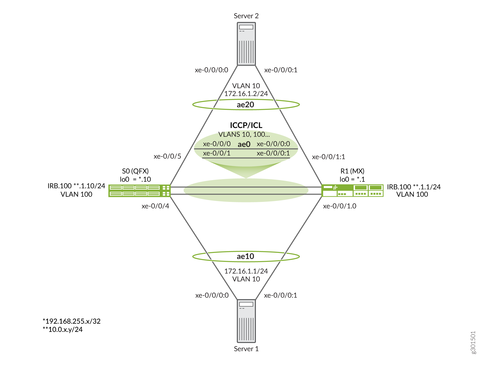
그림 3 은 이 예에서 사용되는 토폴로지를 보여줍니다.
토폴로지에 대한 핵심 사항은 다음과 같습니다.
- S0 노드는 QFX10000 스위치이고 R1 노드는 MX960 라우터입니다.
- MX 시리즈 라우터는 2개의 서버 역할을 수행하는 데 사용됩니다. 이 예에서는 기존의 LACP 기반 LAG 인터페이스를 지원하는 모든 스위치, 라우터 또는 서버 디바이스를 사용할 수 있습니다.
- 서버에는 VLAN 10이 할당되고 공유 서브넷이 있습니다. 서버 간에 레이어 2 연결이 예상됩니다.
- PE 간의 ICCP 세션은 IRB 인터페이스에 고정됩니다. 이는 링크 장애에서 살아남기 위한 루프백 인터페이스 간의 BGP 피어링과 유사합니다. 그러나 여기서 IRB는 PE 간의 레이어 2 연결을 제공하는 공유 VLAN(VLAN 100)에 배치됩니다. 즉, IRB 간의 연결에 IGP 또는 정적 경로가 필요하지 않습니다. 결과적으로 IRB는 IP 서브넷을 공유합니다.
- 이 예는 ICCP와 ICL 기능을 모두 지원하기 위해 PE(ae0) 사이에 단일 LAG 인터페이스를 구축합니다. 원하는 경우 별도의 AE 번들을 통해 ICCP를 실행할 수 있습니다. ICCP/ICL 링크에 사용되는 AE 번들에서 여러 멤버를 사용하는 것은 개별 인터페이스 또는 링크 실패 시 계속 작동하도록 보장하는 것입니다.
- 대체로 유사하지만 MC-LAG 구성은 서로 다른 플랫폼이라는 점을 감안할 때 PE 디바이스 간에 약간 다릅니다. 이러한 구성 차이와 플랫폼 간의 MC-LAG 상호 운용성을 입증하는 것이 이 예제의 이유입니다. 예제를 진행하면서 상호 작용 중인 PE를 추적해야 합니다.
디바이스 구성
CLI 빠른 구성
이 예를 빠르게 구성하려면, 아래 명령을 복사하여 텍스트 파일에 붙여 넣은 다음 모든 라인브레이크를 제거하고, 네트워크 구성을 일치하는 데 필요한 세부 사항을 변경하고, 계층 수준에서 [edit] 명령을 복사하여 CLI에 붙여 넣습니다. 완료되면 구성 모드에서 들어가 commit 변경 사항을 활성화합니다.
스위치 S0
이 예에서 S0 디바이스는 QFX10000 스위치입니다.
set system host-name mc-lag_r0
set chassis aggregated-devices ethernet device-count 10
set interfaces xe-0/0/0 gigether-options 802.3ad ae0
set interfaces xe-0/0/1 gigether-options 802.3ad ae0
set interfaces xe-0/0/4 gigether-options 802.3ad ae10
set interfaces xe-0/0/5 gigether-options 802.3ad ae20
set interfaces ae0 aggregated-ether-options lacp active
set interfaces ae0 unit 0 family ethernet-switching interface-mode trunk
set interfaces ae0 unit 0 family ethernet-switching vlan members all
set interfaces ae10 aggregated-ether-options lacp active
set interfaces ae10 aggregated-ether-options lacp system-id 01:01:01:01:01:01
set interfaces ae10 aggregated-ether-options lacp admin-key 10
set interfaces ae10 aggregated-ether-options mc-ae mc-ae-id 10
set interfaces ae10 aggregated-ether-options mc-ae redundancy-group 1
set interfaces ae10 aggregated-ether-options mc-ae chassis-id 0
set interfaces ae10 aggregated-ether-options mc-ae mode active-active
set interfaces ae10 aggregated-ether-options mc-ae status-control active
set interfaces ae10 unit 0 family ethernet-switching vlan members vlan10
set interfaces ae20 aggregated-ether-options lacp active
set interfaces ae20 aggregated-ether-options lacp system-id 02:02:02:02:02:02
set interfaces ae20 aggregated-ether-options lacp admin-key 20
set interfaces ae20 aggregated-ether-options mc-ae mc-ae-id 20
set interfaces ae20 aggregated-ether-options mc-ae redundancy-group 1
set interfaces ae20 aggregated-ether-options mc-ae chassis-id 1
set interfaces ae20 aggregated-ether-options mc-ae mode active-active
set interfaces ae20 aggregated-ether-options mc-ae status-control standby
set interfaces ae20 unit 0 family ethernet-switching vlan members vlan10
set interfaces irb unit 100 family inet address 10.0.1.10/24
set interfaces lo0 unit 0 family inet address 192.168.255.10/32
set multi-chassis multi-chassis-protection 10.0.1.1 interface ae0
set protocols iccp local-ip-addr 10.0.1.10
set protocols iccp peer 10.0.1.1 session-establishment-hold-time 50
set protocols iccp peer 10.0.1.1 redundancy-group-id-list 1
set protocols iccp peer 10.0.1.1 liveness-detection minimum-interval 1000
set switch-options service-id 100
set vlans vlan10 vlan-id 10
set vlans vlan100 vlan-id 100
set vlans vlan100 l3-interface irb.100
라우터 R1
이 예에서 R1 디바이스는 MX 시리즈 라우터입니다.
set system host-name mc-lag_r1
set chassis aggregated-devices ethernet device-count 10
set interfaces xe-0/0/0:0 gigether-options 802.3ad ae0
set interfaces xe-0/0/0:1 gigether-options 802.3ad ae0
set interfaces xe-0/0/1:0 gigether-options 802.3ad ae10
set interfaces xe-0/0/1:1 gigether-options 802.3ad ae20
set interfaces ae0 aggregated-ether-options lacp active
set interfaces ae0 unit 0 family bridge interface-mode trunk
set interfaces ae0 unit 0 family bridge vlan-id-list 1-1000
set interfaces ae10 aggregated-ether-options lacp active
set interfaces ae10 aggregated-ether-options lacp system-id 01:01:01:01:01:01
set interfaces ae10 aggregated-ether-options lacp admin-key 10
set interfaces ae10 aggregated-ether-options mc-ae mc-ae-id 10
set interfaces ae10 aggregated-ether-options mc-ae redundancy-group 1
set interfaces ae10 aggregated-ether-options mc-ae chassis-id 1
set interfaces ae10 aggregated-ether-options mc-ae mode active-active
set interfaces ae10 aggregated-ether-options mc-ae status-control standby
set interfaces ae10 unit 0 multi-chassis-protection 10.0.1.10 interface ae0.0
set interfaces ae10 unit 0 family bridge interface-mode access
set interfaces ae10 unit 0 family bridge vlan-id 10
set interfaces ae20 aggregated-ether-options lacp active
set interfaces ae20 aggregated-ether-options lacp system-id 02:02:02:02:02:02
set interfaces ae20 aggregated-ether-options lacp admin-key 20
set interfaces ae20 aggregated-ether-options mc-ae mc-ae-id 20
set interfaces ae20 aggregated-ether-options mc-ae redundancy-group 1
set interfaces ae20 aggregated-ether-options mc-ae chassis-id 0
set interfaces ae20 aggregated-ether-options mc-ae mode active-active
set interfaces ae20 aggregated-ether-options mc-ae status-control active
set interfaces ae20 unit 0 multi-chassis-protection 10.0.1.10 interface ae0.0
set interfaces ae20 unit 0 family bridge interface-mode access
set interfaces ae20 unit 0 family bridge vlan-id 10
set interfaces irb unit 100 family inet address 10.0.1.1/24
set interfaces lo0 unit 0 family inet address 192.168.255.1/32
set protocols iccp local-ip-addr 10.0.1.1
set protocols iccp peer 10.0.1.10 session-establishment-hold-time 50
set protocols iccp peer 10.0.1.10 redundancy-group-id-list 1
set protocols iccp peer 10.0.1.10 liveness-detection minimum-interval 1000
set bridge-domains vlan10 vlan-id 10
set bridge-domains vlan100 vlan-id 100
set bridge-domains vlan100 routing-interface irb.100
set switch-options service-id 10
서버 1
이 예의 서버는 MX 라우터입니다. 이 예에서는 PE 디바이스에서 MC-LAG를 구성하는 데 중점을 두지만, 서버 구성은 완전성을 위해 제공됩니다. 이 예제에서 서버 2는 IPv4 주소 172.16.1.2/24 및 IPv6 주소 2001:db8:172:16:1::2가 할당되었다는 점을 제외하고는 동일한 구성을 갖습니다.
set system host-name server1
set chassis aggregated-devices ethernet device-count 10
set interfaces xe-0/0/0:0 gigether-options 802.3ad ae10
set interfaces xe-0/0/0:1 gigether-options 802.3ad ae10
set interfaces ae10 aggregated-ether-options lacp active
set interfaces ae10 unit 0 family inet address 172.16.1.1/24
set interfaces ae10 unit 0 family inet6 address 2001:db8:172:16:1::1/64
S0 스위치 구성
단계별 절차
다음 예에서는 구성 계층에서 다양한 수준을 탐색해야 합니다. CLI 탐색에 대한 정보는 구성 모드에서 CLI 편집기 사용을 참조하십시오.
스위치 S0을 구성하려면 다음을 수행합니다.
섀시에서 지원되는 어그리게이션 이더넷 디바이스의 수를 지정합니다. 이 예에는 3개의 LAG만 필요하지만 미사용 AE 번들 용량이 있어도 문제가 발생하지 않습니다.
[edit chassis]
user@S0# set aggregated-devices ethernet device-count 10
IRB 인터페이스의 VLAN과 함께 루프백(원하는 경우 이 예에서는 사용되지 않음) 및 IRB 인터페이스를 구성합니다. 이 예에서 IRB 인터페이스는 ICCP 세션을 앵커하는 데 사용되며 VLAN 100에 할당됩니다.
[edit]
user@S0# set interfaces lo0 unit 0 family inet address 192.168.255.10/32
user@S0# set interfaces irb unit 100 family inet address 10.0.1.10/24
user@S0# set vlans vlan100 vlan-id 100
user@S0# set vlans vlan100 l3-interface irb.100
ICCP 및 ICL을 지원하도록 ae0 인터페이스를 구성합니다. ICCP를 지원하는 데 사용되는 IRB VLAN뿐만 아니라 모든 MC-LAG VLAN을 포함해야 합니다. VLAN 목록을 지정할 수 있지만, 이 예
all에서는 모든 VLAN이 ae0 인터페이스를 통해 지원되도록 신속하게 확인하기 위해 키워드를 사용합니다. 이 예에서는 ISL에 두 개의 VLAN만 필요합니다. ICCP를 지원하는 MC-LAG VLAN(10) 및 VLAN 100.적절한 작동을 위해서는 QFX 시리즈 스위치의 ICL 링크에 유닛 0을 사용해야 합니다. 이는 MX 시리즈 라우터와 달리 ICL 링크의 유닛 수준 사양을 지원하지 않기 때문입니다.
참고:QFX 시리즈 스위치는 ICL 링크의 인터페이스 수준 사양만 지원하며 유닛 0을 사용한다고 가정합니다. 따라서 그림과 같이 유닛 0 아래에 모든 MC-LAG VLAN을 나열하는 것이 중요합니다. MX 시리즈 라우터는 ICL의 글로벌 또는 단위 수준 사양을 모두 지원할 수 있습니다. 후자의 방법은 이 예의 뒷부분에 나와 있습니다.
[edit interfaces]
user@S0# set xe-0/0/0 gigether-options 802.3ad ae0
user@S0# set xe-0/0/1 gigether-options 802.3ad ae0
user@S0# set ae0 aggregated-ether-options lacp active
user@S0# set ae0 unit 0 family ethernet-switching interface-mode trunk
user@S0# set ae0 unit 0 family ethernet-switching vlan members all
어그리게이션 이더넷 번들을 마주하는 서버에 사용되는 멤버 인터페이스를 지정합니다.
[edit interfaces]
user@S0# set xe-0/0/4 gigether-options 802.3ad ae10
user@S0# set xe-0/0/5 gigether-options 802.3ad ae20
서버 1(ae10)에 연결하는 MC-LAG에 대한 LACP 및 MC-LAG 매개 변수를 구성합니다. MC-LAG는 액티브-액티브 모드로 설정되며, 이 예에서 S0은 문을
status-control active사용하여 활성 MC-LAG 노드로 설정됩니다. S0이 실패하면 R1이 활성 노드로 인계됩니다. 이chassis-id문은 LACP에서 MC-LAG의 물리적 멤버 링크의 포트 번호를 계산하는 데 사용됩니다. 관례에 따라 활성 노드에는 0의 섀시 ID가 할당되고 대기 노드에는 1이 할당됩니다. 이후 단계에서는 R1을 서버 2에 연결된 MC-LAG의 활성 노드로 구성합니다.다중 섀시 어그리게이션 이더넷 식별 번호(mc-ae-id)는 어그리게이션 이더넷 인터페이스가 속하는 링크 어그리게이션 그룹을 지정합니다. S0 및 R1의 ae10 인터페이스는 mc-ae-id 10으로 구성됩니다. 마찬가지로 ae20 인터페이스는 mc-ae-id 20 으로 구성됩니다.
redundancy-group 1이 문은 ICCP에서 유사한 중복 기능을 수행하는 여러 섀시를 연결하고 피어링 섀시의 애플리케이션이 서로 메시지를 보낼 수 있도록 통신 채널을 설정하는 데 사용됩니다. S0 및 R1의 ae10 및 ae20 인터페이스는 동일한 중복 그룹인 중복 그룹 1로 구성됩니다.이 문은
modeMC-LAG가 액티브-스탠바이 모드 또는 액티브-액티브 모드에 있는지 여부를 나타냅니다. 동일한 그룹에 있는 섀시는 동일한 모드에 있어야 합니다.[edit interfaces ae10] user@S0# set aggregated-ether-options lacp active user@S0# set aggregated-ether-options lacp system-id 01:01:01:01:01:01 user@S0# set aggregated-ether-options lacp admin-key 10 user@S0# set aggregated-ether-options mc-ae mc-ae-id 10 user@S0# set aggregated-ether-options mc-ae redundancy-group 1 user@S0# set aggregated-ether-options mc-ae chassis-id 0 user@S0# set aggregated-ether-options mc-ae mode active-active user@S0# set aggregated-ether-options mc-ae status-control active user@S0# set unit 0 family ethernet-switching vlan members vlan10
서버 2(ae20)에 연결하는 MC-LAG에 대한 LACP 및 MC-LAG 매개 변수를 구성합니다. MC-LAG는 액티브-액티브 모드로 설정되며, 이 예에서 S0은 대기 MC-LAG 노드로 설정됩니다. R1 실패 시 S0이 활성 노드로 인계됩니다.
[edit interfaces ae20]
user@S0# set aggregated-ether-options lacp active
user@S0# set interfaces ae20 aggregated-ether-options lacp system-id 02:02:02:02:02:02
user@S0# set aggregated-ether-options lacp admin-key 20
user@S0# set aggregated-ether-options mc-ae mc-ae-id 20
user@S0# set aggregated-ether-options mc-ae redundancy-group 1
user@S0# set aggregated-ether-options mc-ae chassis-id 1
user@S0# set aggregated-ether-options mc-ae mode active-active
user@S0# set aggregated-ether-options mc-ae status-control standby
user@S0# set unit 0 family ethernet-switching vlan members v10
AE 10 및 AE 20 번들에 대한 VLAN을 구성합니다.
[edit]
user@S0# set vlans vlan10 vlan-id 10
스위치 옵션 서비스 ID를 구성합니다.
브리지 도메인 내의 포트는 레이어 2 브리징을 수행하기 위해 동일한 플러딩 또는 브로드캐스트 특성을 공유합니다.
전역
service-id문은 피어(이 경우 S0 및 R1) 간에 관련 브리지 도메인을 링크하는 데 필요하며 동일한 값으로 구성해야 합니다.[edit switch-options] user@S0# set service-id 100
ICCP 매개 변수를 구성합니다. and
peer매개 변수는local각각 로컬 및 원격 IRB 인터페이스에 대해 이전에 구성한 값을 반영하도록 설정됩니다. IRB(또는 루프백) 인터페이스에 대한 ICCP 피어링을 구성하면 개별 링크 장애 발생 시에도 ICCP 세션이 작동 상태를 유지할 수 있습니다.[edit protocols iccp] user@S0# set local-ip-addr 10.0.1.10 user@S0# set peer 10.0.1.1 session-establishment-hold-time 50 user@S0# set peer 10.0.1.1 redundancy-group-id-list 1 user@S0# set peer 10.0.1.10 liveness-detection minimum-interval 1000
글로벌 수준에서 서비스 ID를 구성합니다. 서비스를 제공하는 PE 라우터 집합에서 네트워크 전체에 걸쳐 동일한 고유한 서비스 ID를 구성해야 합니다. 이 서비스 ID는 다중 섀시 어그리게이션 이더넷 인터페이스가 브리지 도메인의 일부일 때 필요합니다.
[edit switch-options]
user@S0# set service-id 100
S0에서 지원하는 MC-LAG 번들에 대한 ICL로 작동하도록 ae0 인터페이스를 구성합니다.
[edit multi-chassis]
user@S0# set multi-chassis-protection 10.0.1.1 interface ae0
참고:QFX 시리즈 스위치에서는 물리적 인터페이스 디바이스를 ICL 보호 링크로 지정해야 합니다. MC-LAG 번들에 대한 ICL의 논리 단위 수준 매핑은 지원되지 않습니다. 적절한 작동을 위해서는 유닛 0이 ICL에서 MC-LAG VLAN의 브리징을 지원하는 데 사용되는지 확인해야 합니다.
S0 결과
구성 모드에서 명령을 입력하여 구성을 확인합니다. show 출력에 의도한 구성이 표시되지 않으면 이 예의 지침을 반복하여 구성을 수정합니다.
[edit]
user@S0# show
. . .chassis {
    aggregated-devices {
        ethernet {
            device-count 10;
        }
    }
}
interfaces {
    xe-0/0/0 {
        gigether-options {
            802.3ad ae0;
        }
    }
    xe-0/0/1 {
        gigether-options {
            802.3ad ae0;
        }
    }
    xe-0/0/4 {
        gigether-options {
            802.3ad ae10;
        }
    }
    xe-0/0/5 {
        gigether-options {
            802.3ad ae20;
        }
    }
    ae0 {
        aggregated-ether-options {
            lacp {
                active;
            }
        }
        unit 0 {
            family ethernet-switching {
                interface-mode trunk;
                vlan {
                    members all;
                }
            }
        }
    }
    ae10 {
        aggregated-ether-options {
            lacp {
                active;
                system-id 01:01:01:01:01:01;
                admin-key 10;
            }
            mc-ae {
                mc-ae-id 10;
                redundancy-group 1;
                chassis-id 0;
                mode active-active;
                status-control active;
            }
        }
        unit 0 {
            family ethernet-switching {
                vlan {
                    members vlan10;
                }
            }
        }
    }
    ae20 {
        aggregated-ether-options {
            lacp {
                active;
                system-id 02:02:02:02:02:02;
                admin-key 20;
            }
            mc-ae {
                mc-ae-id 20;
                redundancy-group 1;
                chassis-id 1;
                mode active-active;
                status-control standby;
            }
        }
        unit 0 {
            family ethernet-switching {
                vlan {
                    members vlan10;
                }
            }
        }
    }
    irb {
        unit 100 {
            family inet {
                address 10.0.1.10/24;
            }
        }
    }
    lo0 {
        unit 0 {
            family inet {
                address 192.168.255.10/32;
            }
        }
    }
}
multi-chassis {
    multi-chassis-protection 10.0.1.1 {
        interface ae0;
    }
}
protocols {
    iccp {
        local-ip-addr 10.0.1.10;
        peer 10.0.1.1 {
            session-establishment-hold-time 50;
            redundancy-group-id-list 1;
            liveness-detection {
                minimum-interval 1000;
            }
        }
    }
}
switch-options {
    service-id 100;
}
vlans {
    vlan10 {
        vlan-id 10;
    }
    vlan100 {
        vlan-id 100;
        l3-interface irb.100;
    }
}
R1 라우터 구성
단계별 절차
다음 예에서는 구성 계층에서 다양한 수준을 탐색해야 합니다. CLI 탐색에 대한 정보는 구성 모드에서 CLI 편집기 사용을 참조하십시오.
라우터 R1을 구성하려면 다음을 수행합니다.
섀시에 생성할 어그리게이션 이더넷 인터페이스의 수를 지정합니다. 3개의 LAG만 필요하지만 추가 LAG 용량이 있어도 문제가 발생하지 않습니다.
[edit chassis]
user@R1# set aggregated-devices ethernet device-count 10
IRB 인터페이스의 VLAN과 함께 루프백(원하는 경우 이 예에서는 필요하지 않음) 및 IRB 인터페이스를 구성합니다. 이 예에서 IRB 인터페이스는 ICCP 세션을 앵커하는 데 사용됩니다.
[edit]
user@R1# set interfaces lo0 unit 0 family inet address 192.168.255.1/32
user@R1# set interfaces irb unit 100 family inet address 10.0.1.1/24
user@R1# set bridge-domains vlan100 vlan-id 100
user@R1# set bridge-domains vlan100 routing-interface irb.100
ICL 및 ICCP 기능을 모두 지원하도록 ae0 인터페이스를 구성합니다. A
vlan-id-list는 ICCP용 VLAN 100 및 MC-LAG용 VLAN 10을 포함하는 다양한 VLAN을 지원하는 데 사용됩니다. QFX 시리즈 스위치와 달리, 모든 VLAN을 지원하기 위한 바로 가기로 사용되는 기능은allMX 시리즈 라우터에서 지원되지 않습니다.참고:ICL 링크는 ICCP에 사용되는 VLAN뿐만 아니라 모든 MC-LAG VLAN을 지원해야 합니다. 이 예에서 ae0 링크가 ISL과 ICCP를 모두 지원한다는 점을 감안할 때 최소한 VLAN 10 및 VLAN 100을 나열해야 함을 의미합니다.
[edit interfaces]
user@R1# set xe-0/0/0:0 gigether-options 802.3ad ae0
user@R1# set xe-0/0/0:1 gigether-options 802.3ad ae0
user@R1# set ae0 aggregated-ether-options lacp active
user@R1# set ae0 unit 0 family bridge interface-mode trunk
user@R1# set ae0 unit 0 family bridge vlan-id-list 2-1000
R0에서 어그리게이션 이더넷 번들을 마주하는 서버에 포함될 멤버를 지정합니다.
[edit interfaces]
user@R1# set xe-0/0/1:0 gigether-options 802.3ad ae10
user@R1# set xe-0/0/1:1 gigether-options 802.3ad ae20
서버 1(ae10)에 연결하는 MC-LAG에 대한 LACP 및 MC-LAG 매개 변수를 구성합니다. MC-LAG는 액티브-액티브 모드로 설정되며, 이 예에서 R1은 문을
status-control standby사용하여 대기 MC-LAG 노드로 설정됩니다. 이로 인해 S0은 작동 중일 때 ae10에 대한 활성 MC-LAG 노드가 됩니다. S0이 실패하면 R1이 활성 노드로 인계받습니다. 이chassis-id문은 LACP에서 MC-LAG의 물리적 멤버 링크의 포트 번호를 계산하는 데 사용됩니다. 관례에 따라 활성 노드에는 0의 섀시 ID가 할당되고 대기 노드에는 1이 할당됩니다.다중 섀시 어그리게이션 이더넷 식별 번호(
mc-ae-id)는 어그리게이션 이더넷 인터페이스가 속한 링크 어그리게이션 그룹을 지정합니다. S0 및 R1의 ae10 인터페이스는 mc-ae-id 10으로 구성됩니다. 마찬가지로 ae20 인터페이스는 mc-ae-id 20으로 구성됩니다.redundancy-group 1이 문은 ICCP에서 유사한 중복 기능을 수행하는 여러 섀시를 연결하고 피어링 섀시의 애플리케이션이 서로 메시지를 보낼 수 있도록 통신 채널을 설정하는 데 사용됩니다. S0 및 R1의 ae10 및 ae20 인터페이스는 동일한 중복 그룹인 중복 그룹 1로 구성됩니다.이 문은
modeMC-LAG가 액티브-스탠바이 모드 또는 액티브-액티브 모드에 있는지 여부를 나타냅니다. 동일한 그룹에 있는 섀시는 동일한 모드에 있어야 합니다.이 예는 단위 수준(아래 표시된 MC-LAG 단위 아래)에서 ICL 인터페이스 사양에 대한 MX 시리즈 라우터 지원을 보여줍니다. 원하는 경우 QFX 시리즈 스위치 S0에 표시된 것처럼 계층의
[edit multi-chassis multi-chassis-protection]물리적 디바이스 수준(유닛 0 가정)에서 ICL 보호 링크를 전역으로 지정할 수 있습니다.[edit interfaces ae10] user@R1# set aggregated-ether-options lacp active user@R1# set aggregated-ether-options lacp system-id 01:01:01:01:01:01 user@R1# set aggregated-ether-options lacp admin-key 10 user@R1# set aggregated-ether-options mc-ae mc-ae-id 10 user@R1# set aggregated-ether-options mc-ae redundancy-group 1 user@R1# set aggregated-ether-options mc-ae chassis-id 1 user@R1# set aggregated-ether-options mc-ae mode active-active user@R1# set aggregated-ether-options mc-ae status-control standby user@R1# set ae10 unit 0 family bridge interface-mode access user@R1# set ae10 unit 0 family bridge vlan-id 10 user@R1# set ae10 unit 0 multi-chassis-protection 10.0.1.10 interface ae0.0
참고:MX 플랫폼에서는 계층에서
edit multi-chassis multi-chassis-protection글로벌 수준의 물리적 디바이스 선언을 사용하거나 여기에 나온 것처럼 MC-LAG 번들 내의 논리적 단위 수준에서 ICL 인터페이스를 지정할 수 있습니다. QFX 시리즈 스위치는 물리적 디바이스의 글로벌 수준 사양만 지원합니다.서버 2(ae20)에 연결하는 MC-LAG에 대한 LACP 및 MC-LAG 매개 변수를 구성합니다. MC-LAG는 액티브-액티브 모드로 설정되며, 이 예에서 R1은 활성 MC-LAG 노드로 설정됩니다. R1 실패 시 S0은 ae20 MC-LAG의 활성 노드로 인계됩니다.
[edit interfaces ae20]
user@R1# set aggregated-ether-options lacp active
user@R1# set aggregated-ether-options lacp system-id 02:02:02:02:02:02
user@R1# set aggregated-ether-options lacp admin-key 20
user@R1# set aggregated-ether-options mc-ae mc-ae-id 20
user@R1# set aggregated-ether-options mc-ae redundancy-group 1
user@R1# set aggregated-ether-options mc-ae chassis-id 0
user@R1# set aggregated-ether-options mc-ae mode active-active
user@R1# set aggregated-ether-options mc-ae status-control active
user@R1# set unit 0 family bridge interface-mode access
user@R1# set unit 0 family bridge vlan-id 10
user@R1# set unit 0 multi-chassis-protection 10.0.1.10 interface ae0.0
ae10 및 ae20 번들에 대한 VLAN을 구성합니다.
참고:MX 시리즈 라우터에서 계층 아래에 VLAN을 정의합니다.
[edit bridge-domains]QFX 시리즈 스위치에서는 계층에서[edit vlans]이 작업을 수행합니다. 이것이 QFX 시리즈 스위치와 MX 시리즈 라우터의 차이점 중 하나입니다.[edit bridge-domains] user@R1# set vlan10 vlan-id 10
스위치 옵션 서비스 ID를 구성합니다.
브리지 도메인 내의 포트는 레이어 2 브리징을 수행하기 위해 동일한 플러딩 또는 브로드캐스트 특성을 공유합니다.
전역
service-id문은 피어(이 경우 S0 및 R1) 간에 관련 브리지 도메인을 링크하는 데 필요하며 동일한 값으로 구성해야 합니다.[edit switch-options] user@R1# set service-id 100
ICCP 매개 변수를 구성합니다. and
peer매개 변수는local각각 로컬 및 원격 IRB 인터페이스에서 이전에 구성된 값을 반영하도록 설정됩니다. IRB(또는 루프백) 인터페이스에 대한 ICCP 피어링을 구성하면 개별 링크 장애 발생 시에도 ICCP 세션이 작동 상태를 유지할 수 있습니다.[edit protocols iccp] user@R1# set local-ip-addr 10.0.1.1 user@R1# set peer 10.0.1.10 session-establishment-hold-time 50 user@R1# set peer 10.0.1.10 redundancy-group-id-list 1 user@R1# set peer 10.0.1.10 liveness-detection minimum-interval 1000
글로벌 수준에서 서비스 ID를 구성합니다. 서비스를 제공하는 PE 디바이스 집합에서 서비스에 대해 동일한 고유한 네트워크 전체 구성을 구성해야 합니다. 이 서비스 ID는 다중 섀시 어그리게이션 이더넷 인터페이스가 브리지 도메인의 일부인 경우에 필요합니다.
[edit switch-options]
user@R1# set service-id 100
R1 결과
구성 모드에서 명령을 입력하여 구성을 확인합니다. show 출력에 의도한 구성이 표시되지 않으면 이 예의 지침을 반복하여 구성을 수정합니다.
[edit]
user@R1# show
. . .
chassis {
    aggregated-devices {
        ethernet {
            device-count 10;
        }
    }
}
interfaces {
    xe-0/0/0:0 {
        gigether-options {
            802.3ad ae0;
        }
    }
    xe-0/0/0:1 {
        gigether-options {
            802.3ad ae0;
        }
    }
    xe-0/0/0:2 {
        gigether-options {
            802.3ad ae1;
        }
    }
    xe-0/0/0:3 {
        gigether-options {
            802.3ad ae1;
        }
    }
    xe-0/0/1:0 {
        gigether-options {
            802.3ad ae10;
        }
    }
    xe-0/0/1:1 {
        gigether-options {
            802.3ad ae20;
        }
    }
    ae0 {
        aggregated-ether-options {
            lacp {
                active;
            }
        }
        unit 0 {
            family bridge {
                interface-mode trunk;
                vlan-id-list 2-1000;
            }
        }
    }
    ae10 {
        aggregated-ether-options {
            lacp {
                active;
                system-id 01:01:01:01:01:01;
                admin-key 10;
            }
            mc-ae {
                mc-ae-id 10;
                redundancy-group 1;
                chassis-id 1;
                mode active-active;
                status-control standby;
            }
        }
        unit 0 {
            multi-chassis-protection 10.0.1.10 {
                interface ae0.0;
            }
            family bridge {
                interface-mode access;
                vlan-id 10;
            }
        }
    }
    ae20 {
        aggregated-ether-options {
            lacp {
                active;
                system-id 02:02:02:02:02:02;
                admin-key 20;
            }
            mc-ae {
                mc-ae-id 20;
                redundancy-group 1;
                chassis-id 0;
                mode active-active;
                status-control active;
            }
        }
        unit 0 {
            multi-chassis-protection 10.0.1.10 {
                interface ae0.0;
            }
            family bridge {
                interface-mode access;
                vlan-id 10;
            }
        }
    }
    irb {
        unit 100 {
            family inet {
                address 10.0.1.1/24;
            }
        }
    }
    lo0 {
        unit 0 {
            family inet {
                address 192.168.255.1/32;
            }
        }
    }
}
protocols {
    iccp {
        local-ip-addr 10.0.1.1;
        peer 10.0.1.10 {
            session-establishment-hold-time 50;
            redundancy-group-id-list 1;
            liveness-detection {
                minimum-interval 1000;
            }
        }
    }
}
bridge-domains {
    vlan10 {
        vlan-id 10;
    }
    vlan100 {
        vlan-id 100;
        routing-interface irb.100;
    }
}
switch-options {
    service-id 100;
}
검증
다음 운영 모드 명령을 실행하여 구성이 제대로 작동하고 있는지 확인합니다.
show iccpshow interfaces mc-ae \show interfaces aeX (0, 10, and 20)QFX 시리즈 스위치에서 및
show vlansshow ethernet-switching table명령을 사용합니다MX 시리즈 라우터에서 다음
show bridge mac-table명령을 사용합니다서버 간의 레이어 2 연결을 확인합니다
예상되는 출력을 표시하기 위해 확인 명령을 선택합니다. S0의 명령으로 show iccp 시작합니다. ICCP 세션이 설정되지 않은 경우 IRB 인터페이스 간에 ping 명령을 실행하여 ae0 ICCP/ICL 링크를 통해 예상되는 레이어 2 연결을 보장합니다.
user@S0# show iccp
Redundancy Group Information for peer 10.0.1.1
  TCP Connection       : Established
  Liveliness Detection : Up
  Redundancy Group ID          Status
    1                           Up

Client Application: l2ald_iccpd_client
  Redundancy Group IDs Joined: 1

Client Application: lacpd
  Redundancy Group IDs Joined: 1
다음으로 S0에서 명령을 실행 show interfaces mc-ae extensive 합니다. 출력은 두 MC-LAG에 대해 예상되는 활성-활성 상태와 상태 제어 활성/대기 상태를 확인합니다. 이 예에서 S0은 ae10에 대한 상태 제어 활성 노드이고 ae20에 대한 대기 노드입니다.
user@S0# show interfaces mc-lag extensive
 Member Link                  : ae10
 Current State Machine's State: mcae active state
 Local Status                 : active
 Local State                  : up
 Peer Status                  : active
 Peer State                   : up
     Logical Interface        : ae10.0
     Topology Type            : bridge
     Local State              : up
     Peer State               : up
     Peer Ip/MCP/State        : 10.0.1.1 ae0.0 up

 MCAE Configuration
     Redundancy Group         : 1
     MCAE ID                  : 10
     MCAE Mode                : active_active
     Status Control           : active
     Chassis ID               : 0
 LACP Configuration
     System ID                : 01:01:01:01:01:01
     Admin Key                : 10
 LACP Information
     Local Partner System ID  : 2c:6b:f5:20:55:c0
     Peer Partner System ID   : 2c:6b:f5:20:55:c0

 Member Link                  : ae20
 Current State Machine's State: mcae active state
 Local Status                 : active
 Local State                  : up
 Peer Status                  : active
 Peer State                   : up
     Logical Interface        : ae20.0
     Topology Type            : bridge
     Local State              : up
     Peer State               : up
     Peer Ip/MCP/State        : 10.0.1.1 ae0.0 up

 MCAE Configuration
     Redundancy Group         : 1
     MCAE ID                  : 20
     MCAE Mode                : active_active
     Status Control           : standby
     Chassis ID               : 1
 LACP Configuration
     System ID                : 02:02:02:02:02:02
     Admin Key                : 20
 LACP Information
     Local Partner System ID  : 2c:6b:f5:13:24:c0
     Peer Partner System ID   : 2c:6b:f5:13:24:c0
show interfaces 이 명령은 ICCP/ICL과 MC-LAG 번들이 작동 중인지 확인하는 데 사용됩니다. 간결성을 위해 ae10 번들의 출력만 표시됩니다. 모든 AE 인터페이스(ae0, ae10, ae20)가 작동 중이어야 합니다.
user@S0# show interfaces ae10
 Physical interface: ae10 (MC-AE-10, active), Enabled, Physical link is Up
  Interface index: 670, SNMP ifIndex: 561
  Link-level type: Ethernet, MTU: 1514, Speed: 10Gbps, BPDU Error: None, Ethernet-Switching Error: None, MAC-REWRITE Error: None,
  Loopback: Disabled, Source filtering: Disabled, Flow control: Disabled, Minimum links needed: 1, Minimum bandwidth needed: 1bps
  Device flags   : Present Running
  Interface flags: SNMP-Traps Internal: 0x4000
  Current address: 02:05:86:72:a9:f7, Hardware address: 02:05:86:72:a9:f7
  Last flapped   : 2021-04-08 11:56:43 PDT (02:37:24 ago)
  Input rate     : 0 bps (0 pps)
  Output rate    : 992 bps (0 pps)

  Logical interface ae10.0 (Index 578) (SNMP ifIndex 562)
    Flags: Up SNMP-Traps 0x24024000 Encapsulation: Ethernet-Bridge
    Statistics        Packets        pps         Bytes          bps
    Bundle:
        Input :          9454          0        963310          776
        Output:          9429          0       1204640          968
    Adaptive Statistics:
        Adaptive Adjusts:          0
        Adaptive Scans  :          0
        Adaptive Updates:          0
    Protocol eth-switch, MTU: 1514
show vlans detail and show ethernet-switching table 명령은 S0 디바이스의 ICCP/ICL 및 MC-LAG 인터페이스에 대한 VLAN 정의 및 매핑을 확인하는 데 사용됩니다.
user@S0# show vlans detail
 Routing instance: default-switch
VLAN Name: vlan10                            State: Active
Tag: 10
Internal index: 3, Generation Index: 3, Origin: Static
MAC aging time: 300 seconds
VXLAN Enabled : No
Interfaces:
    ae0.0*,tagged,trunk
    ae10.0*,untagged,access
    ae20.0*,untagged,access
Number of interfaces: Tagged 1    , Untagged 2
Total MAC count: 2

Routing instance: default-switch
VLAN Name: vlan100                        State: Active
Tag: 100
Internal index: 2, Generation Index: 2, Origin: Static
MAC aging time: 300 seconds
Layer 3 interface: irb.100
VXLAN Enabled : No
Interfaces:
    ae0.0*,tagged,trunk
Number of interfaces: Tagged 1    , Untagged 0
Total MAC count:

show ethernet-switching table
MAC flags (S - static MAC, D - dynamic MAC, L - locally learned, P - Persistent static, C - Control MAC
           SE - statistics enabled, NM - non configured MAC, R - remote PE MAC, O - ovsdb MAC)


Ethernet switching table : 2 entries, 2 learned
Routing instance : default-switch
    Vlan                MAC                 MAC         Age    Logical                NH        RTR
    name                address             flags              interface              Index     ID
    vlan10                 2c:6b:f5:13:24:c2   DLR           -   ae20.0                 0         0
    vlan10                 2c:6b:f5:20:55:c3   DL            -   ae10.0                 0         0
마지막으로 서버 1과 2 사이를 ping하여 레이어 2 연결을 확인합니다.
user@Server1# ping 172.16.1.2 count 2
 PING 172.16.1.2 (172.16.1.2): 56 data bytes
64 bytes from 172.16.1.2: icmp_seq=0 ttl=64 time=56.529 ms
64 bytes from 172.16.1.2: icmp_seq=1 ttl=64 time=117.029 ms

--- 172.16.1.2 ping statistics ---
2 packets transmitted, 2 packets received, 0% packet loss
round-trip min/avg/max/stddev = 56.529/86.779/117.029/30.250 ms
user@Server1# ping 2001:db8:172:16:1::2 count 2
PING6(56=40+8+8 bytes) 2001:db8:172:16:1::1 --> 2001:db8:172:16:1::2
16 bytes from 2001:db8:172:16:1::2, icmp_seq=0 hlim=64 time=154.164 ms
16 bytes from 2001:db8:172:16:1::2, icmp_seq=1 hlim=64 time=167.032 ms

--- 2001:db8:172:16:1::2 ping6 statistics ---
2 packets transmitted, 2 packets received, 0% packet loss
round-trip min/avg/max/std-dev = 154.164/160.598/167.032/6.434 ms
예: 캠퍼스 네트워크용 코어의 EX9200 스위치에서 멀티섀시 링크 어그리게이션 구성
캠퍼스 구성의 MC-LAG를 사용하면 두 개 이상의 물리적 링크를 코어 어그리게이션 또는 어그리게이션 액세스 스위치 간의 논리적 링크로 결합할 수 있습니다. MC-LAG는 표준 LAG(Link Aggregation Group)를 통해 여러 스위치 간의 액티브/액티브 링크를 제공하여 가용성을 향상시키고, 스패닝 트리 프로토콜(STP)의 필요성을 제거하며, 링크 및 디바이스 장애 시 더 빠른 레이어 2 컨버전스를 제공합니다. 여러 활성 네트워크 경로를 통해 MC-LAG를 사용하면 여러 물리적 링크에서 트래픽을 로드 밸런싱할 수 있습니다. 링크가 실패하면 트래픽은 사용 가능한 다른 링크를 통해 전달될 수 있으며 집계된 링크는 계속 사용할 수 있습니다.
- 요구 사항
- 개요
- 구성
- (선택 사항) RSTP 구성
- (선택 사항) IGMP 스누핑 구성
- (선택 사항) VRRP 구성
- (선택 사항) MAC 주소 동기화 구성
- (선택 사항) OSPF 구성
- (선택 사항) PIM 구성
- (선택 사항) DHCP 릴레이 구성
- 검증
요구 사항
이 예에서 사용되는 하드웨어 및 소프트웨어 구성 요소는 다음과 같습니다.
-
EX 시리즈용 Junos OS 릴리스 13.2R5.10
-
EX9200 스위치 2개
이 구성 예는 나열된 소프트웨어 릴리스를 사용하여 테스트되었으며 이후 모든 릴리스에서 작동한다고 가정합니다.
MC-LAG를 구성하기 전에 다음 방법을 이해해야 합니다.
-
스위치에 어그리게이션 이더넷 인터페이스를 구성합니다. 어그리게이션 이더넷 인터페이스 구성을 참조하십시오.
-
스위치의 어그리게이션 이더넷 인터페이스에 LACP(Link Aggregation Control Protocol)를 구성합니다. 어그리게이션 이더넷 LACP 구성(CLI 절차)을 참조하십시오.
개요
이 예에서는 두 개의 어그리게이션 이더넷 인터페이스, 섀시 간 링크 보호 링크(ICL-PL), ICL-PL을 위한 멀티섀시 보호 링크, MC-LAG를 호스팅하는 피어를 위한 ICCP 및 MC-LAG 피어 간의 레이어 3 연결로 구성된 두 스위치에 걸쳐 MC-LAG를 구성합니다. ICCP에는 레이어 3 연결이 필요합니다.
토폴로지
이 예에서 사용되는 토폴로지는 MC-LAG를 호스팅하는 두 개의 스위치로 구성됩니다. 두 개의 스위치는 EX4600 스위치와 MX80 라우터에 연결됩니다. 그림 4 는 이 예의 토폴로지를 보여줍니다.
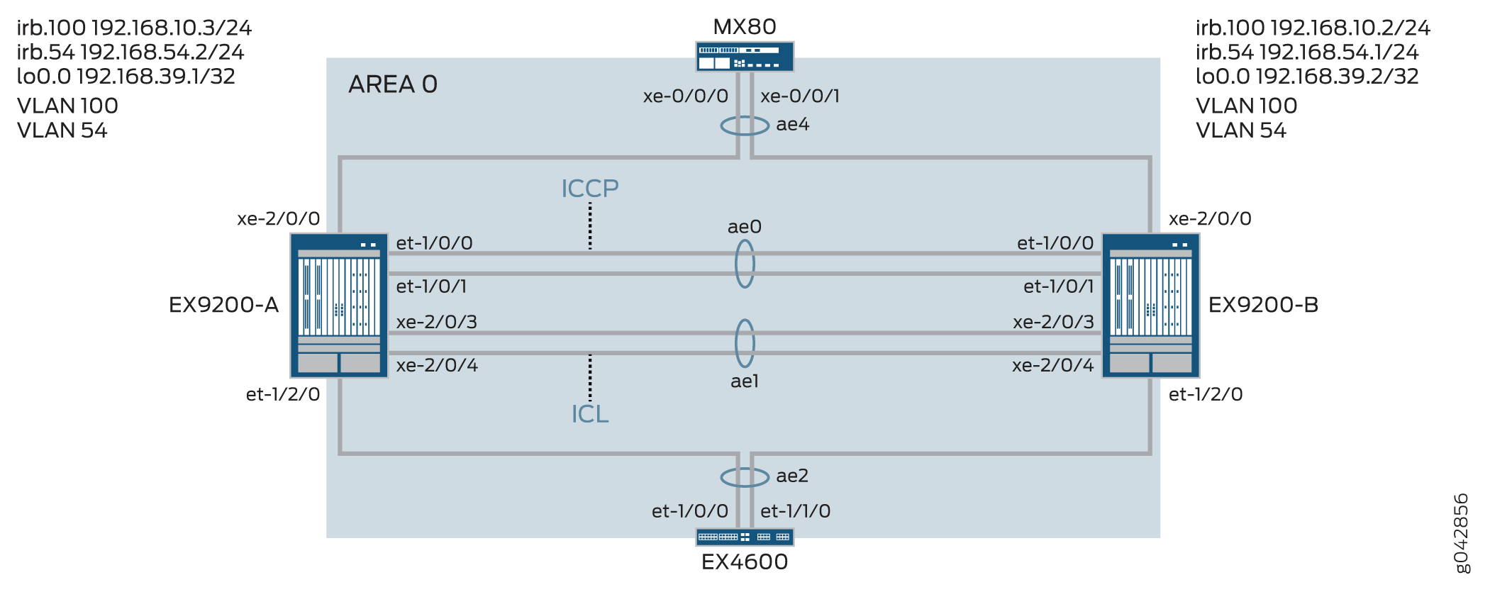
표 1에는 이 구성 예에서 사용되는 토폴로지가 자세히 나와 있습니다.
| 호스트 이름 | 기본 하드웨어 | 다중 섀시 링크 어그리게이션 그룹 |
|---|---|---|
| EX9200-A EX9200-B |
EX9200 EX9200 |
ae0은 어그리게이션 이더넷 인터페이스로 구성되며, ICCP 링크로 사용됩니다. 다음 인터페이스는 ae0의 일부입니다: EX9200-A의 et-1/0/0 및 et-1/0/1, EX9200-B의 et-1/0/0 및 et-1/0/1. ae1은 어그리게이션 이더넷 인터페이스로 구성되며 ICL 링크로 사용되며, 다음 두 인터페이스는 ae1의 일부입니다: EX9200-A의 xe-2/0/3 및 xe-2/0/4, EX9200-B의 xe-2/0/3 및 xe-2/0/4. ae2는 MC-LAG로 구성되며, 다음 인터페이스가 ae2 의 일부입니다: EX9200-A의 et-1/2/0 및 EX9200-B의 et-1/2/0. ae4는 MC-LAG로 구성되며, 다음 인터페이스는 ae4 의 일부입니다: EX9200-A의 xe-2/0/0 및 EX9200-B의 xe-2/0/0. |
구성
CLI 빠른 구성
이 예를 빠르게 구성하려면, 아래 명령을 복사하여 텍스트 파일에 붙여 넣은 다음 모든 라인브레이크를 제거하고, 네트워크 구성을 일치하는 데 필요한 세부 사항을 변경하고, 계층 수준에서 [edit] 명령을 복사하여 CLI에 붙여 넣은 다음, 구성 모드에서 입력합니다 commit .
EX9200-A
set chassis aggregated-devices ethernet device-count 20
set interfaces et-1/0/0 ether-options 802.3ad ae0
set interfaces et-1/0/1 ether-options 802.3ad ae0
set interfaces et-1/2/0 ether-options 802.3ad ae2
set interfaces xe-2/0/3 hold-time up 100
set interfaces xe-2/0/3 hold-time down 9000
set interfaces xe-2/0/3 ether-options 802.3ad ae1
set interfaces xe-2/0/4 hold-time up 100
set interfaces xe-2/0/4 hold-time down 9000
set interfaces xe-2/0/4 ether-options 802.3ad ae1
set interfaces xe-2/0/0 ether-options 802.3ad ae4
set interfaces ae0 aggregated-ether-options lacp active
set interfaces ae0 aggregated-ether-options lacp periodic fast
set interfaces ae0 unit 0 family inet address 192.168.90.1/24
set interfaces ae1 description ICL-LINK
set interfaces ae1 aggregated-ether-options lacp active
set interfaces ae1 aggregated-ether-options lacp periodic fast
set interfaces ae1 unit 0 family ethernet-switching interface-mode trunk
set interfaces ae1 unit 0 family ethernet-switching vlan members all
set interfaces ae2 aggregated-ether-options lacp active
set interfaces ae2 aggregated-ether-options lacp periodic fast
set interfaces ae2 aggregated-ether-options lacp system-id 00:01:02:03:04:05
set interfaces ae2 aggregated-ether-options lacp admin-key 3
set interfaces ae2 aggregated-ether-options mc-ae mc-ae-id 3
set interfaces ae2 aggregated-ether-options mc-ae redundancy-group 1
set interfaces ae2 aggregated-ether-options mc-ae chassis-id 0
set interfaces ae2 aggregated-ether-options mc-ae mode active-active
set interfaces ae2 aggregated-ether-options mc-ae status-control active
set interfaces ae2 aggregated-ether-options mc-ae init-delay-time 520
set interfaces ae2 aggregated-ether-options mc-ae events iccp-peer-down prefer-status-control-active
set interfaces ae2 unit 0 family ethernet-switching interface-mode trunk
set interfaces ae2 unit 0 family ethernet-switching vlan members all
set interfaces ae4 aggregated-ether-options lacp active
set interfaces ae4 aggregated-ether-options lacp periodic fast
set interfaces ae4 aggregated-ether-options lacp system-id 00:01:02:03:04:06
set interfaces ae4 aggregated-ether-options lacp admin-key 7
set interfaces ae4 aggregated-ether-options mc-ae mc-ae-id 7
set interfaces ae4 aggregated-ether-options mc-ae redundancy-group 1
set interfaces ae4 aggregated-ether-options mc-ae chassis-id 0
set interfaces ae4 aggregated-ether-options mc-ae mode active-active
set interfaces ae4 aggregated-ether-options mc-ae status-control active
set interfaces ae4 aggregated-ether-options mc-ae init-delay-time 520
set interfaces ae4 aggregated-ether-options mc-ae events iccp-peer-down prefer-status-control-active
set interfaces ae4 unit 0 family ethernet-switching interface-mode trunk
set interfaces ae4 unit 0 family ethernet-switching vlan members v54
set vlans rack_1 vlan-id 100
set vlans rack_1 vlan-id 54
set vlans rack_1 l3-interface irb.100
set vlans v54 l3-interface irb.54
set interfaces irb unit 54 family inet address 192.168.54.2/24 arp 192.168.54.1 l2-interface ae1.0
set interfaces irb unit 54 family inet address 192.168.54.2/24 arp 192.168.54.1 mac 3c:8a:b0:85:78:70
set interfaces irb unit 100 family inet address 192.168.10.3/24 arp 192.168.10.2 l2-interface ae1.0
set interfaces irb unit 100 family inet address 192.168.10.3/24 arp 192.168.10.2 mac 3c:8a:b0:85:78:70
set interfaces lo0 unit 0 family inet address 192.168.39.1/32
set protocols iccp local-ip-addr 192.168.39.1
set protocols iccp peer 192.168.39.2 session-establishment-hold-time 50
set protocols iccp peer 192.168.39.2 redundancy-group-id-list 1
set protocols iccp peer 192.168.39.2 backup-liveness-detection backup-peer-ip 10.105.5.6
set protocols iccp peer 192.168.39.2 liveness-detection minimum-interval 2000
set protocols iccp peer 192.168.39.2 liveness-detection multiplier 4
set multi-chassis multi-chassis-protection 192.168.39.2 interface ae1
set switch-options service-id 1
EX9200-B
set chassis aggregated-devices ethernet device-count 20
set interfaces et-1/0/0 ether-options 802.3ad ae0
set interfaces et-1/0/1 ether-options 802.3ad ae0
set interfaces et-1/2/0 ether-options 802.3ad ae2
set interfaces xe-2/0/0 ether-options 802.3ad ae4
set interfaces xe-2/0/3 hold-time up 100
set interfaces xe-2/0/3 hold-time down 9000
set interfaces xe-2/0/3 ether-options 802.3ad ae1
set interfaces xe-2/0/4 hold-time up 100
set interfaces xe-2/0/4 hold-time down 9000
set interfaces xe-2/0/4 ether-options 802.3ad ae1
set interfaces ae0 aggregated-ether-options lacp active
set interfaces ae0 aggregated-ether-options lacp periodic fast
set interfaces ae0 unit 0 family inet address 192.168.90.2/24
set interfaces ae1 description ICL-LINK
set interfaces ae1 aggregated-ether-options lacp active
set interfaces ae1 aggregated-ether-options lacp periodic fast
set interfaces ae1 unit 0 family ethernet-switching interface-mode trunk
set interfaces ae1 unit 0 family ethernet-switching vlan members all
set interfaces ae2 aggregated-ether-options lacp active
set interfaces ae2 aggregated-ether-options lacp periodic fast
set interfaces ae2 aggregated-ether-options lacp system-id 00:01:02:03:04:05
set interfaces ae2 aggregated-ether-options lacp admin-key 3
set interfaces ae2 aggregated-ether-options mc-ae mc-ae-id 3
set interfaces ae2 aggregated-ether-options mc-ae redundancy-group 1
set interfaces ae2 aggregated-ether-options mc-ae chassis-id 1
set interfaces ae2 aggregated-ether-options mc-ae mode active-active
set interfaces ae2 aggregated-ether-options mc-ae init-delay-time 520
set interfaces ae2 aggregated-ether-options mc-ae events

set interfaces ae2 aggregated-ether-options mc-ae status-control standby
set interfaces ae2 unit 0 family ethernet-switching interface-mode trunk
set interfaces ae2 unit 0 family ethernet-switching vlan members all
set interfaces ae4 aggregated-ether-options lacp active
set interfaces ae4 aggregated-ether-options lacp periodic fast
set interfaces ae4 aggregated-ether-options lacp system-id 00:01:02:03:04:06
set interfaces ae4 aggregated-ether-options lacp admin-key 7
set interfaces ae4 aggregated-ether-options mc-ae mc-ae-id 7
set interfaces ae4 aggregated-ether-options mc-ae redundancy-group 1
set interfaces ae4 aggregated-ether-options mc-ae chassis-id 1
set interfaces ae4 aggregated-ether-options mc-ae mode active-active
set interfaces ae4 aggregated-ether-options mc-ae status-control standby
set interfaces ae4 aggregated-ether-options mc-ae init-delay-time 520
set interfaces ae4 unit 0 family ethernet-switching interface-mode trunk
set interfaces ae4 unit 0 family ethernet-switching vlan members v54
set vlans rack_1 vlan-id 100
set vlans rack_1 l3-interface irb.100
set vlans v54 vlan-id 54
set vlans v54 l3-interface irb.54
set interfaces irb unit 54 family inet address 192.168.54.1/24 arp 192.168.54.2 l2-interface ae1.0
set interfaces irb unit 54 family inet address 192.168.54.1/24 arp 192.168.54.2 mac 00:1f:12:b6:6f:f0
set interfaces irb unit 100 family inet address 192.168.10.2/24 arp 192.168.10.3 l2-interface ae1.0
set interfaces irb unit 100 family inet address 192.168.10.2/24 arp 192.168.10.3 mac 00:1f:12:b6:6f:f0
set interfaces lo0 unit 0 family inet address 192.168.39.2/32
set protocols iccp local-ip-addr 192.168.39.2
set protocols iccp peer 192.168.39.1 session-establishment-hold-time 50
set protocols iccp peer 192.168.39.1 redundancy-group-id-list 1
set protocols iccp peer 192.168.39.1 backup-liveness-detection backup-peer-ip 10.105.5.5
set protocols iccp peer 192.168.39.1 liveness-detection minimum-interval 2000
set protocols iccp peer 192.168.39.1 liveness-detection multiplier 4
set multi-chassis multi-chassis-protection 192.168.39.1 interface ae1
set switch-options service-id 1
스위치 A에서 MC-LAG 구성
단계별 절차
다음 예에서는 구성 계층에서 다양한 수준을 탐색해야 합니다.
-
스위치 A에서 생성할 어그리게이션 이더넷 인터페이스의 수를 구성합니다.
[edit chassis]
user@switch# set aggregated-devices ethernet device-count 20
-
ICCP(Inter-Chassis Control Protocol) 인터페이스에 사용될 어그리게이션 이더넷 인터페이스에 멤버 인터페이스를 추가합니다.
[edit interfaces]
user@switch# set et-1/0/0 ether-options 802.3ad ae0
user@switch# set et-1/0/1 ether-options 802.3ad ae0
-
인터페이스 ae2에 속하는 멤버 인터페이스를 지정합니다.
[edit interfaces]
user@switch# set et-1/2/0 ether-options 802.3ad ae2
-
구성된 BFD 타이머보다 높은 홀드 타임 값으로 섀시 간 링크(ICL)의 멤버 인터페이스를 구성하여 ICCP 링크가 다운되기 전에 ICL이 다운된 것으로 보급되는 것을 방지합니다.
ICCP 링크가 다운되기 전에 ICL이 다운되면 대기 상태 제어 피어로 구성된 MC-LAG 인터페이스가 켜짐과 꺼짐을 반복합니다. 인터페이스가 오르락내리락하면 컨버전스에 지연이 발생합니다.
[edit interfaces]
user@switch# set xe-2/0/3 hold-time up 100
user@switch# set xe-2/0/3 hold-time down 9000
user@switch# set xe-2/0/3 ether-options 802.3ad ae1
user@switch# set xe-2/0/4 hold-time up 100
user@switch# set xe-2/0/4 hold-time down 9000
user@switch# set xe-2/0/4 ether-options 802.3ad ae1
-
ae4에 속하는 멤버를 지정합니다.
ae4에 속하는 멤버를 지정합니다.
[edit interfaces]
user@switch# set xe-2/0/0 ether-options 802.3ad ae4
-
ae0을 레이어 3 인터페이스로 구성합니다.
[edit interfaces]
user@switch# set ae0 aggregated-ether-options lacp active
user@switch# set ae0 aggregated-ether-options lacp periodic fast
user@switch# set ae0 unit 0 family inet address 192.168.90.1/24
-
ae1을 레이어 2 인터페이스로 구성합니다.
[edit interfaces]
user@switch# set ae1 description ICL-LINK
user@switch# set ae1 aggregated-ether-options lacp active
user@switch# set ae1 aggregated-ether-options lacp periodic fast
-
EX9200-A와 EX9200-B 간의 트렁크 인터페이스를 구성합니다.
[edit interfaces]
user@switch# set ae1 unit 0 family ethernet-switching interface-mode trunk
user@switch# set ae1 unit 0 family ethernet-switching vlan members all
-
ae2에서 LACP 매개 변수를 구성합니다.
[edit interfaces]
user@switch# set ae2 aggregated-ether-options lacp active
user@switch# set ae2 aggregated-ether-options lacp periodic fast
-
LACP 시스템 ID를 구성합니다.
[edit interfaces]
user@switch# set ae2 aggregated-ether-options lacp system-id 00:01:02:03:04:06
-
MC-AE 인터페이스 속성을 구성합니다.
[edit interfaces]
user@switch# set ae2 aggregated-ether-options lacp admin-key 3
user@switch# set ae2 aggregated-ether-options mc-ae mc-ae-id 3
user@switch# set ae2 aggregated-ether-options mc-ae redundancy-group 1
-
어그리게이션 이더넷 인터페이스가 속한 MC-LAG에 대한 고유한 섀시 ID를 지정합니다.
[edit interfaces]
user@switch# set ae2 aggregated-ether-options mc-ae chassis-id 0
-
어그리게이션 이더넷 인터페이스가 속하는 MC-LAG의 모드를 지정합니다.
[edit interfaces]
user@switch# set ae2 aggregated-ether-options mc-ae mode active-active
-
MC-LAG를 호스팅하는 스위치에서 상태 제어를 구성합니다.
하나의 스위치가 활성 모드에 있으면 다른 스위치는 대기 모드에 있어야 합니다.
[edit interfaces]
user@switch# set ae2 aggregated-ether-options mc-ae status-control active
-
라우팅 인접성이 형성되어야 하는 시간을 초 단위로 지정합니다.
[edit interfaces]
user@switch# set ae2 aggregated-ether-options mc-ae init-delay-time 520
-
MC-LAG 그룹의 피어가 다운되면 status-control active로 구성된 피어가 활성 피어가 되도록 지정합니다.
[edit interfaces]
user@switch# set ae2 aggregated-ether-options mc-ae events iccp-peer-down prefer-status-control-active
-
ae2를 모든 VLAN의 멤버십을 가진 트렁크 포트로 구성합니다.
[edit interfaces]
user@switch# set ae2 unit 0 family ethernet-switching interface-mode trunk
user@switch# set ae2 unit 0 family ethernet-switching vlan members all
-
ae4에서 LACP 매개 변수를 구성합니다.
[edit interfaces]
user@switch# set ae4 aggregated-ether-options lacp active
user@switch# set ae4 aggregated-ether-options lacp periodic fast
-
LACP 관리 키를 지정합니다.
[edit interfaces]
user@switch# set ae4 aggregated-ether-options lacp system-id 00:01:02:03:04:06
user@switch# set ae4 aggregated-ether-options lacp admin-key 7
user@switch# set ae4 aggregated-ether-options mc-ae mc-ae-id 7
user@switch# set ae4 aggregated-ether-options mc-ae redundancy-group 1
-
어그리게이션 이더넷 인터페이스가 속한 MC-LAG에 대한 고유한 섀시 ID를 지정합니다.
[edit interfaces]
user@switch# set ae4 aggregated-ether-options mc-ae chassis-id 0
user@switch# set ae4 aggregated-ether-options mc-ae mode active-active
-
MC-LAG를 호스팅하는 스위치에서 상태 제어를 구성합니다.
하나의 스위치가 활성 모드에 있으면 다른 스위치는 대기 모드에 있어야 합니다.
[edit interfaces]
user@switch# set ae4 aggregated-ether-options mc-ae status-control active
user@switch# set ae4 aggregated-ether-options mc-ae init-delay-time 520
user@switch# set ae4 aggregated-ether-options mc-ae events iccp-peer-down prefer-status-control-active
-
ae4를 레이어 2 인터페이스로 구성합니다.
[edit interfaces]
user@switch# set ae4 unit 0 family ethernet-switching interface-mode trunk
user@switch# set ae4 unit 0 family ethernet-switching vlan members v54
-
VLAN rack_1를 구성하고 VLAN rack_1에서 레이어 3 IRB 인터페이스를 구성합니다.
[edit vlans]
user@switch# set rack_1 vlan-id 100
user@switch# set rack_1 l3-interface irb.100
-
VLAN rack_1 구성합니다.
[edit vlans]
user@switch# set rack_1 vlan-id 54
-
VLAN 54를 구성하고 VLAN 54에서 레이어 3 IRB를 구성합니다.
[edit vlans]
user@switch# set v54 vlan-id 54
user@switch# set v54 l3-interface irb.54
-
VLAN 54에서 IRB 인터페이스를 구성합니다.
라우팅 프로토콜이 IRB 인터페이스를 통해 통과할 수 있도록 MC-LAG 피어에서 정적 ARP를 구성해야 합니다.
[edit interfaces]
user@switch# set irb unit 54 family inet address 192.168.54.2/24 arp 192.168.54.1 l2-interface ae1.0
user@switch# set irb unit 54 family inet address 192.168.54.2/24 arp 192.168.54.1 mac 3c:8a:b0:85:78:70
-
MC-LAG 피어에서 정적 ARP를 구성하여 라우팅 프로토콜이 IRB 인터페이스를 통해 통과할 수 있도록 합니다
[edit interfaces]
user@switch# set irb unit 100 family inet address 192.168.10.3/24 arp 192.168.10.2 l2-interface ae1.0
user@switch# set irb unit 100 family inet address 192.168.10.3/24 arp 192.168.10.2 mac 3c:8a:b0:85:78:70
-
루프백 인터페이스를 구성합니다.
[edit interfaces]
user@switch# set lo0 unit 0 family inet address 192.168.39.2/32
-
루프백 주소를 사용하여 ICCP를 구성합니다.
[edit protocols]
user@switch# set iccp local-ip-addr 192.168.39.1
-
ICCP가 더 빠르게 연결되도록 세션 설정 보류 시간을 구성합니다.
[edit protocols]
user@switch# set iccp peer 192.168.39.2 session-establishment-hold-time 50
user@switch# set iccp peer 192.168.39.2 redundancy-group-id-list 1
user@switch# set iccp peer 192.168.39.2 backup-liveness-detection backup-peer-ip 10.105.5.6
-
BFD(Bidirectional Forwarding Detection)를 활성화하려면 최소 수신 간격을 구성합니다.
최소 수신 간격 값은 6초로 설정하는 것이 좋습니다.
[edit protocols]
user@switch# set iccp peer 192.168.39.2 liveness-detection minimum-interval 2000
user@switch# set iccp peer 192.168.39.2 liveness-detection multiplier 4
[edit multi-chassis]
user@switch# set multi-chassis-protection 192.168.39.2 interface ae1
-
스위치 서비스 ID를 지정합니다.
스위치 서비스 ID는 MC-LAG 멤버 간에 애플리케이션, IGMP, ARP 및 MAC 학습을 동기화하는 데 사용됩니다.
[edit switch-options]
user@switch# set service-id 1
스위치 B에서 MC-LAG 구성
단계별 절차
다음 예에서는 구성 계층에서 다양한 수준을 탐색해야 합니다.
-
스위치 A에서 생성할 어그리게이션 이더넷 인터페이스의 수를 구성합니다.
[edit chassis]
user@switch# set aggregated-devices ethernet device-count 20
-
ICCP(Inter-Chassis Control Protocol) 인터페이스에 사용될 어그리게이션 이더넷 인터페이스에 멤버 인터페이스를 추가합니다.
[edit interfaces]
user@switch# set et-1/0/0 ether-options 802.3ad ae0
user@switch# set et-1/0/1 ether-options 802.3ad ae0
-
인터페이스 ae2에 속하는 멤버 인터페이스를 지정합니다.
[edit interfaces]
user@switch# set et-1/2/0 ether-options 802.3ad ae2
-
구성된 BFD 타이머보다 높은 홀드 타임 값으로 섀시 간 링크(ICL)의 멤버 인터페이스를 구성하여 ICCP 링크가 다운되기 전에 ICL이 다운된 것으로 보급되는 것을 방지합니다.
ICCP 링크가 다운되기 전에 ICL이 다운되면 대기 상태 제어 피어로 구성된 MC-LAG 인터페이스가 켜짐과 꺼짐을 반복합니다. 인터페이스가 오르락내리락하면 컨버전스에 지연이 발생합니다.
[edit interfaces]
user@switch# set xe-2/0/3 hold-time up 100
user@switch# set xe-2/0/3 hold-time down 9000
user@switch# set xe-2/0/3 ether-options 802.3ad ae1
user@switch# set xe-2/0/4 hold-time up 100
user@switch# set xe-2/0/4 hold-time down 9000
user@switch# set xe-2/0/4 ether-options 802.3ad ae1
-
ae4에 속하는 멤버를 지정합니다.
[edit interfaces]
user@switch# set xe-2/0/0 ether-options 802.3ad ae4
-
ae0을 레이어 3 인터페이스로 구성합니다.
[edit interfaces]
user@switch# set ae0 aggregated-ether-options lacp active
user@switch# set ae0 aggregated-ether-options lacp periodic fast
user@switch# set ae0 unit 0 family inet address 192.168.90.2/24
-
ae1을 레이어 2 인터페이스로 구성합니다.
[edit interfaces]
user@switch# set ae1 description ICL-LINK
user@switch# set ae1 aggregated-ether-options lacp active
user@switch# set ae1 aggregated-ether-options lacp periodic fast
-
EX9200-A와 EX9200-B 간의 트렁크 인터페이스를 구성합니다.
[edit interfaces]
user@switch# set ae1 unit 0 family ethernet-switching interface-mode trunk
user@switch# set ae1 unit 0 family ethernet-switching vlan members all
-
ae2에서 LACP 매개 변수를 구성합니다.
[edit interfaces]
user@switch# set ae2 aggregated-ether-options lacp active
user@switch# set ae2 aggregated-ether-options lacp periodic fast
-
LACP 시스템 ID를 구성합니다.
[edit interfaces]
user@switch# set ae2 aggregated-ether-options lacp system-id 00:01:02:03:04:05
-
MC-AE 인터페이스 속성을 구성합니다.
[edit interfaces]
user@switch# set ae2 aggregated-ether-options lacp admin-key 3
user@switch# set ae2 aggregated-ether-options mc-ae mc-ae-id 3
user@switch# set ae2 aggregated-ether-options mc-ae redundancy-group 1
-
어그리게이션 이더넷 인터페이스가 속한 MC-LAG에 대한 고유한 섀시 ID를 지정합니다.
[edit interfaces]
user@switch# set ae2 aggregated-ether-options mc-ae chassis-id 1
-
어그리게이션 이더넷 인터페이스가 속하는 MC-LAG의 모드를 지정합니다.
[edit interfaces]
user@switch# set ae2 aggregated-ether-options mc-ae mode active-active
-
라우팅 인접성이 형성되어야 하는 시간을 초 단위로 지정합니다.
[edit interfaces]
user@switch# set ae2 aggregated-ether-options mc-ae init-delay-time 520
-
MC-LAG를 호스팅하는 스위치에서 상태 제어를 구성합니다.
하나의 스위치가 활성 모드에 있으면 다른 스위치는 대기 모드에 있어야 합니다.
[edit interfaces]
user@switch# set ae2 aggregated-ether-options mc-ae status-control standby
-
ae2를 모든 VLAN의 멤버십을 가진 트렁크 포트로 구성합니다.
[edit interfaces]
user@switch# set ae2 unit 0 family ethernet-switching interface-mode trunk
user@switch# set ae2 unit 0 family ethernet-switching vlan members all
-
ae4에서 LACP 매개 변수를 구성합니다.
[edit interfaces]
user@switch# set ae4 aggregated-ether-options lacp active
user@switch# set ae4 aggregated-ether-options lacp periodic fast
-
LACP 관리 키를 지정합니다.
[edit interfaces]
user@switch# set ae4 aggregated-ether-options lacp system-id 00:01:02:03:04:06
user@switch# set ae4 aggregated-ether-options lacp admin-key 7
user@switch# set ae4 aggregated-ether-options mc-ae mc-ae-id 7
user@switch# set ae4 aggregated-ether-options mc-ae redundancy-group 1
-
어그리게이션 이더넷 인터페이스가 속한 MC-LAG에 대한 고유한 섀시 ID를 지정합니다.
[edit interfaces]
user@switch# set ae4 aggregated-ether-options mc-ae chassis-id 1
user@switch# set ae4 aggregated-ether-options mc-ae mode active-active
-
MC-LAG를 호스팅하는 스위치에서 상태 제어를 구성합니다.
하나의 스위치가 활성 모드에 있으면 다른 스위치는 대기 모드에 있어야 합니다.
[edit interfaces]
user@switch# set ae4 aggregated-ether-options mc-ae status-control standby
user@switch# set ae4 aggregated-ether-options mc-ae init-delay-time 520
user@switch# set ae4 aggregated-ether-options mc-ae events iccp-peer-down prefer-status-control-active
-
ae4를 레이어 2 인터페이스로 구성합니다.
[edit interfaces]
user@switch# set ae4 unit 0 family ethernet-switching interface-mode trunk
user@switch# set ae4 unit 0 family ethernet-switching vlan members v54
-
VLAN rack_1를 구성하고 VLAN rack_1에서 레이어 3 IRB 인터페이스를 구성합니다.
[edit vlans]
user@switch# set rack_1 vlan-id 100
user@switch# set rack_1 l3-interface irb.100
-
VLAN 54를 구성하고 VLAN 54에서 IRB를 구성합니다.
[edit vlans]
user@switch# set v54 vlan-id 54
user@switch# set v54 l3-interface irb.54
-
MC-LAG 피어에 정적 ARP를 구성하여 라우팅 프로토콜이 IRB 인터페이스를 통과할 수 있도록 합니다.
[edit interfaces]
user@switch# set irb unit 54 family inet address 192.168.54.1/24 arp 192.168.54.2 l2-interface ae1.0
user@switch# set irb unit 54 family inet address 192.168.54.1/24 arp 192.168.54.2 mac mac 00:1f:12:b6:6f:f0
-
라우팅 프로토콜이 IRB 인터페이스를 통과할 수 있도록 MC-LAG IRB 피어에 정적 ARP(Address Resolution Protocol)를 구성합니다.
[edit interfaces]
user@switch# set irb unit 100 family inet address 192.168.10.2/24 arp 192.168.10.3 l2-interface ae1.0
user@switch# set irb unit 100 family inet address 192.168.10.2/24 arp 192.168.10.3 mac 00:1f:12:b6:6f:f0
-
루프백 인터페이스를 구성합니다.
[edit interfaces]
user@switch# set lo0 unit 0 family inet address 192.168.39.2/32
-
루프백 주소를 사용하여 ICCP를 구성합니다.
[edit protocols]
user@switch# set iccp local-ip-addr 192.168.39.2
-
ICCP가 더 빠르게 연결되도록 세션 설정 보류 시간을 구성합니다.
[edit protocols]
user@switch# set iccp peer 192.168.39.1 session-establishment-hold-time 50
user@switch# set iccp peer 192.168.39.1 redundancy-group-id-list 1
user@switch# set iccp peer 192.168.39.1 backup-liveness-detection backup-peer-ip 10.105.5.5
-
BFD(Bidirectional Forwarding Detection)를 활성화하려면 최소 수신 간격을 구성합니다.
최소 수신 간격 값은 6초로 설정하는 것이 좋습니다.
[edit protocols]
user@switch# set iccp peer 192.168.39.1 liveness-detection minimum-interval 2000
user@switch# set iccp peer 192.168.39.1 liveness-detection multiplier 4
[edit multi-chassis]
user@switch# set multi-chassis-protection 192.168.39.1 interface ae1
-
스위치 서비스 ID를 지정합니다.
스위치 서비스 ID는 MC-LAG 멤버 간에 애플리케이션, IGMP, ARP 및 MAC 학습을 동기화하는 데 사용됩니다.
[edit switch-options]
user@switch# set service-id 1
결과
EX9200-A에 구성 결과를 표시합니다.
user@switch> show chassis
    chassis {
        redundancy {
            graceful-switchover;
        }
        aggregated-devices {
            ethernet {
                device-count 20;
            }
        }
    }
user@switch> show interfaces
    interfaces {
        et-1/0/0 {
            ether-options {
                802.3ad ae0;
            }
        }
        et-1/0/1 {
            ether-options {
                802.3ad ae0;
            }
        }
        et-1/2/0 {
            ether-options {
                802.3ad ae2;
            }
        }
        xe-2/0/3 {
            hold-time up 100 down 7000;
            ether-options {
                802.3ad ae1;
            }
        }
        xe-2/0/4 {
            hold-time up 100 down 7000;
            ether-options {
                802.3ad ae1;
            }
        }
        ae0 {
            aggregated-ether-options {
                lacp {
                    active;
                    periodic fast;
                }
            }
            unit 0 {
                family inet {
                    address 192.168.90.1/24;
                }
            }
        }
        ae1 {
            description ICL-LINK;
            aggregated-ether-options {
                lacp {
                    active;
                    periodic fast;
                }
            }
            unit 0 {
                family ethernet-switching {
                    interface-mode trunk;
                    vlan {
                        members all;
                    }
                }
            }
        }
        ae2 {
            aggregated-ether-options {
                lacp {
                    active;
                    periodic fast;
                    system-id 00:01:02:03:04:05;
                    admin-key 3;
                }
                mc-ae {
                    mc-ae-id 3;
                    redundancy-group 1;
                    chassis-id 0;
                    mode active-active;
                    status-control active;
                    init-delay-time 520;
                    events {
                        iccp-peer-down {
                            prefer-status-control-active;
                        }
                    }
                }
            }
            unit 0 {
                family ethernet-switching {
                    interface-mode trunk;
                    vlan {
                        members all;
                    }
                }
            }
        }
        ae4 {
            aggregated-ether-options {
                lacp {
                    active;
                    periodic fast;
                    system-id 00:01:02:03:04:06;
                    admin-key 7;
                }
                mc-ae {
                    mc-ae-id 7;
                    redundancy-group 1;
                    chassis-id 0;
                    mode active-active;
                    status-control standby;
                    init-delay-time 520;
                    events {
                        iccp-peer-down {
                            prefer-status-control-active;
                        }
                    }
                }
            }
                unit 0 {
                    family ethernet-switching {
                        interface-mode trunk;
                        vlan {
                            members [ rack_1 v54 ];
                        }
                    }
            irb {
                arp-l2-validate;
                    unit 54 {
                        family inet {
                            address 192.168.54.2/24 {
                                arp 192.168.54.1 l2-interface ae1.0 mac 3c:8a:b0:85:78:70;
                            }
                        }
                    }
                        unit 100 {
                            family inet {
                                address 192.168.10.3/24 {
                                    arp 192.168.10.2 l2-interface ae1.0 mac 3c:8a:b0:85:78:70;
                                }
                            }
                        }
                }
                lo0 {
                    unit 0 {
                        family inet {
                            address 192.168.39.1/32;
                        }
                    }
                }
user@switch> show multi-chassis
    multi-chassis {
        multi-chassis-protection 192.168.39.2 {
            interface ae1;
        }
    }
user@switch> show protocols
    protocols {
        iccp {
            local-ip-addr 192.168.39.1;
            peer 192.168.39.2 {
                session-establishment-hold-time 50;
                redundancy-group-id-list 1;
                backup-liveness-detection {
                    backup-peer-ip 10.105.5.6;
                }
                liveness-detection {
                    minimum-interval 2000;
                    multiplier 3;
                }
            }
        }
        lldp {
            interface all;
        }
        layer2-control {
            nonstop-bridging;
        }
    }
user@switch> show switch-options
    switch-options {
        service-id 1;
    }
user@switch> show vlans
    vlans {
        rack_1 {
            vlan-id 100;
            l3-interface irb.100;

        }
            v54 {
                vlan-id 54;
                l3-interface irb.54;
            }
        }
EX9200-B에 구성 결과를 표시합니다.
user@switch> show chassis
    chassis {
        redundancy {
            graceful-switchover;
        }
        aggregated-devices {
            ethernet {
                device-count 20;
            }
        }
    }
user@switch> show interfaces
    interfaces {
        et-1/0/0 {
            ether-options {
                802.3ad ae0;
            }
        }
        et-1/0/1 {
            ether-options {
                802.3ad ae0;
            }
        }
        et-1/2/0 {
            ether-options {
                802.3ad ae2;
            }
        }
        xe-2/0/3 {
            hold-time up 100 down 7000;
            ether-options {
                802.3ad ae1;
            }
        }
        xe-2/0/4 {
            hold-time up 100 down 7000;
            ether-options {
                802.3ad ae1;
            }
        }
        ae0 {
            aggregated-ether-options {
                lacp {
                    active;
                    periodic fast;
                }
            }
                unit 0 {
                    family inet {
                    address 192.168.90.2/24;
                }
        }
        ae1 {
            description ICL-LINK;
            aggregated-ether-options {
                lacp {
                    active;
                    periodic fast;
                }
            }
            unit 0 {
                family ethernet-switching {
                    interface-mode trunk;
                    vlan {
                        members all;
                    }
                }
            }
        }
        ae2 {
            aggregated-ether-options {
                lacp {
                    active;
                    periodic fast;
                    system-id 00:01:02:03:04:05;
                    admin-key 3;
                }
                mc-ae {
                    mc-ae-id 3;
                    redundancy-group 1;
                    chassis-id 1;
                    mode active-active;
                    status-control active;
                    init-delay-time 520;
                    events {
                        iccp-peer-down {
                            prefer-status-control-active;
                        }
                    }
                }
            }
            unit 0 {
                family ethernet-switching {
                    interface-mode trunk;
                    vlan {
                        members all;
                    }
                }
            }
        }
        ae4 {
            aggregated-ether-options {
                lacp {
                    active;
                    periodic fast;
                    system-id 00:01:02:03:04:06;
                    admin-key 7;
                }
                mc-ae {
                    mc-ae-id 7;
                    redundancy-group 1;
                    chassis-id 1;
                    mode active-active;
                    status-control standby;
                    init-delay-time 520;
                }
            }
                unit 0 {
                    family ethernet-switching {
                        interface-mode trunk;
                        vlan {
                            members [rack_1 v54 ];
                        }
                    }
            irb {
            arp-l2-validate;
                unit 54 {
                    family inet {
                        address 192.168.54.1/24 {
                            arp 192.168.54.2 l2-interface ae1.0 mac 00:1f:12:b6:6f:f0;
                        }
                    }
                }
                    unit 100 {
                        family inet {
                            address 192.168.10.2/24 {
                                arp 192.168.10.3 l2-interface ae1.0 mac 00:1f:12:b6:6f:f0;
                            }
                        }
                    }
            lo0 {
                    unit 0 {
                        family inet {
                            address 192.168.39.2/32;
                        }
                    }
user@switch> show multi-chassis
    multi-chassis {
        multi-chassis-protection 192.168.39.1 {
            interface ae1;
        }
    }
user@switch> show protocols
    protocols {
        iccp {
            local-ip-addr 192.168.39.2;
            peer 192.168.39.1 {
                session-establishment-hold-time 50;
                redundancy-group-id-list 1;
                backup-liveness-detection {
                    backup-peer-ip 10.105.5.5;
                }
                liveness-detection {
                    minimum-interval 2000;
                    multiplier 3;
                }
            }
        }
        lldp {
            interface all;
        }
        layer2-control {
            nonstop-bridging;
        }
    }
user@switch> show switch-options
    switch-options {
        service-id 1;
    }
user@switch> show vlans
    vlans {
            rack_1 {
                vlan-id 100;
                l3-interface irb.100;

            }
            v54 {
                vlan-id 54;
                l3-interface irb.54;
            }
        }
(선택 사항) RSTP 구성
CLI 빠른 구성
스위치 A 및 스위치 B
set protocols rstp interface ae2
set protocols rstp interface ae4
set protocols rstp system-identifier 00:01:02:03:04:05
set protocols rstp bridge-priority 0
스위치 A 및 스위치 B 구성
단계별 절차
다음 예에서는 구성 계층에서 다양한 수준을 탐색해야 합니다. CLI 탐색에 대한 정보는 구성 모드에서 CLI 편집기 사용을 참조하십시오.
스위치 A 및 스위치 B를 구성하려면 다음을 수행합니다.
-
선택적 루프 방지를 위해 ae2 및 ae4 인터페이스에서 Rapid Spanning Tree Protocol을 활성화합니다.
[edit protocols]
user@switch# set rstp interface ae2
user@switch# set rstp interface ae4
-
시스템 식별자를 구성합니다.
[edit protocols]
user@switch# set rstp system-identifier 00:01:02:03:04:05
-
빠른 스패닝 트리 프로토콜 우선 순위를 0으로 설정합니다. 이렇게 하면 MC-AE 노드가 가장 높은 우선 순위가 됩니다.
[edit protocols]
user@switch# set rstp bridge-priority 0
스위치 A 및 스위치 B
구성 모드에서 명령을 입력하여 구성을 확인합니다. show protocols rstp 출력에 의도한 구성이 표시되지 않으면 이 예의 지침을 반복하여 구성을 수정합니다.
user@switch> show protocols rstp
rstp {
system-identifier 00:01:02:03:04:05;
interface ae2;
interface ae4;
}
(선택 사항) IGMP 스누핑 구성
CLI 빠른 구성
스위치 A 및 스위치 B
set protocols igmp-snooping vlan rack_1 set protocols igmp-snooping vlan v54 set multicast-snooping-options multichassis-lag-replicate-state set protocols igmp-snooping vlan rack_1 interface ae1.0 multicast-router-interface set protocols igmp-snooping vlan v54 interface ae1.0 multicast-router-interface
스위치 A 및 스위치 B 구성
단계별 절차
다음 예에서는 구성 계층에서 다양한 수준을 탐색해야 합니다. CLI 탐색에 대한 정보는 구성 모드에서 CLI 편집기 사용을 참조하십시오.
스위치 A 및 스위치 B를 구성하려면 다음을 수행합니다.
-
모든 VLAN에 대해 IGMP 스누핑을 활성화합니다.
[edit protocols] user@switch# set igmp-snooping vlan rack_1 user@switch# set igmp-snooping vlan v54
-
브리지 도메인이 구성되면 MC-LAG 피어 간에 멀티캐스트 상태를 동기화합니다.
글로벌 수준에서 IGMP 참가 및 탈퇴 메시지는 MC-LAG 인터페이스 활성 링크에서 대기 링크로 복제되어 페일오버 후 멤버십 정보를 더 빠르게 복구할 수 있습니다.
[edit multicast-snooping-options] user@switch# set multichassis-lag-replicate-state
-
ICL-PL 인터페이스를 라우터 대면 인터페이스로 구성합니다.
[edit protocols] user@switch# set igmp-snooping vlan rack_1 interface ae1.0 multicast-router-interface user@switch# set igmp-snooping vlan v54 interface ae1.0 multicast-router-interface
스위치 A 및 스위치 B
구성 모드에서 and show multicast-snooping-options 명령을 입력 show protocols igmp 하여 구성을 확인합니다. 출력에 의도한 구성이 표시되지 않으면 이 예의 지침을 반복하여 구성을 수정합니다.
user@switch> show protocols igmp
igmp-snooping {
vlan rack_1 {
interface ae1.0 {
multicast-router-interface;
}
}
vlan v54 {
interface ae1.0 {
multicast-router-interface;
}
}
}
user@switch> show multicast-snooping-options
multicast-snooping-options {
multichassis-lag-replicate-state;
}
(선택 사항) VRRP 구성
VRRP 및 MAC 주소 동기화를 모두 구성할 수 없습니다.
CLI 빠른 구성
스위치 A
set interfaces irb unit 100 family inet address 192.168.10.3/24 vrrp-group 1 virtual-address 192.168.10.1 set interfaces irb unit 100 family inet address 192.168.10.3/24 vrrp-group 1 priority 150 set interfaces irb unit 100 family inet address 192.168.10.3/24 vrrp-group 1 accept-data set interfaces irb unit 54 family inet address 192.168.54.2/24 vrrp-group 4 virtual-address 192.168.54.3 set interfaces irb unit 54 family inet address 192.168.54.2/24 vrrp-group 4 priority 200
스위치 B
set interfaces irb unit 100 family inet address 192.168.10.2/24 vrrp-group 1 virtual-address 192.168.10.1 set interfaces irb unit 100 family inet address 192.168.10.2/24 vrrp-group 1 priority 200 set interfaces irb unit 100 family inet address 192.168.10.2/24 vrrp-group 1 accept-data set interfaces irb unit 54 family inet address 192.168.54.1/24 vrrp-group 4 virtual-address 192.168.54.3 set interfaces irb unit 54 family inet address 192.168.54.1/24 vrrp-group 4 priority 150
스위치 A 구성
단계별 절차
다음 예에서는 구성 계층에서 다양한 수준을 탐색해야 합니다. CLI 탐색에 대한 정보는 구성 모드에서 CLI 편집기 사용을 참조하십시오.
스위치 A를 구성하려면 다음을 수행합니다.
-
각 MC-LAG에 대한 IRB 인터페이스를 생성하여 MC-LAG에서 VRRP를 활성화하고, VRRP 그룹의 각 스위치 간에 공유되는 가상 IP 주소를 할당하며, VRRP 그룹의 각 개별 멤버에 개별 IP 주소를 할당합니다.
[edit interfaces] user@switch# set irb unit 100 family inet address 192.168.10.3/24 vrrp-group 1 virtual-address 192.168.10.1 user@switch# set irb unit 100 family inet address 192.168.10.3/24 vrrp-group 1 priority 150 user@switch# set irb unit 100 family inet address 192.168.10.3/24 vrrp-group 1 accept-data
-
각 MC-LAG에 대한 IRB 인터페이스를 생성하여 MC-LAG에서 VRRP를 활성화하고, VRRP 그룹의 각 스위치 간에 공유되는 가상 IP 주소를 할당하며, VRRP 그룹의 각 개별 멤버에 개별 IP 주소를 할당합니다.
[edit interfaces] user@switch# set irb unit 54 family inet address 192.168.54.2/24 vrrp-group 4 virtual-address 192.168.54.3 user@switch# set irb unit 54 family inet address 192.168.54.2/24 vrrp-group 4 priority 200
스위치 A
구성 모드에서 and show interfaces irb unit 100 family inet address 192.168.54.2/24 vrrp-group 명령을 입력 show interfaces irb unit 100 family inet address 192.168.10.3/24 vrrp-group 하여 구성을 확인합니다. 출력에 의도한 구성이 표시되지 않으면 이 예의 지침을 반복하여 구성을 수정합니다.
user@switch> show interfaces irb unit 100 family inet address 192.168.10.3/24 vrrp-group
vrrp-group 1 {
virtual-address 192.168.10.1;
priority 150;
accept-data;
}
user@switch> show interfaces irb unit 100 family inet address 192.168.54.2/24 vrrp-group
vrrp-group 4 {
virtual-address 192.168.54.3;
priority 150;
}
스위치 B 구성
단계별 절차
다음 예에서는 구성 계층에서 다양한 수준을 탐색해야 합니다. CLI 탐색에 대한 정보는 구성 모드에서 CLI 편집기 사용을 참조하십시오.
스위치 A를 구성하려면 다음을 수행합니다.
-
각 MC-LAG에 대한 IRB 인터페이스를 생성하여 MC-LAG에서 VRRP를 활성화하고, VRRP 그룹의 각 스위치 간에 공유되는 가상 IP 주소를 할당하며, VRRP 그룹의 각 개별 멤버에 개별 IP 주소를 할당합니다.
[edit interfaces] user@switch# set irb unit 100 family inet address 192.168.10.2/24 vrrp-group 1 virtual-address 192.168.10.1 user@switch# set irb unit 100 family inet address 192.168.10.2/24 vrrp-group 1 priority 150 user@switch# set irb unit 100 family inet address 192.168.10.2/24 vrrp-group 1 accept-data
-
각 MC-LAG에 대한 IRB 인터페이스를 생성하여 MC-LAG에서 VRRP를 활성화하고, VRRP 그룹의 각 스위치 간에 공유되는 가상 IP 주소를 할당하며, VRRP 그룹의 각 개별 멤버에 개별 IP 주소를 할당합니다.
[edit interfaces] user@switch# set irb unit 54 family inet address 192.168.54.1/24 vrrp-group 4 virtual-address 192.168.54.3 user@switch# set irb unit 54 family inet address 192.168.54.1/24 vrrp-group 4 priority 150
스위치 B
구성 모드에서 명령을 입력하여 구성을 확인합니다. show protocols rstp 출력에 의도한 구성이 표시되지 않으면 이 예의 지침을 반복하여 구성을 수정합니다.
user@switch> show interfaces irb unit 100 family inet address 192.168.10.2/24 vrrp-group
vrrp-group 1 {
virtual-address 192.168.10.1;
priority 200;
accept-data;
}
user@switch> show interfaces irb unit 100 family inet address 192.168.54.1/24 vrrp-group
vrrp-group 4 {
virtual-address 192.168.54.3;
priority 150;
}
(선택 사항) MAC 주소 동기화 구성
MAC 동기화와 VRRP를 모두 구성할 수는 없습니다.
두 MC-LAG 피어의 VLAN에 있는 IRB 인터페이스에서 동일한 IP 주소를 구성해야 합니다.
CLI 빠른 구성
스위치 A 및 스위치 B
set vlans v100 mcae-mac-synchronize set vlans v54 mcae-mac-synchronize
스위치 A 및 스위치 B 구성
단계별 절차
다음 예에서는 구성 계층에서 다양한 수준을 탐색해야 합니다. CLI 탐색에 대한 정보는 구성 모드에서 CLI 편집기 사용을 참조하십시오.
스위치 A를 구성하려면 다음을 수행합니다.
-
스위치 A와 스위치 B의 MC-LAG VLAN에서 MAC 주소 동기화를 구성합니다.
[edit] user@switch# set vlans v100 mcae-mac-synchronize [edit] user@switch# set vlans v54 mcae-mac-synchronize
스위치 A 및 스위치 B
구성 모드에서 and show vlans v54 명령을 입력 show vlans v100 하여 구성을 확인합니다. 출력에 의도한 구성이 표시되지 않으면 이 예의 지침을 반복하여 구성을 수정합니다.
user@switch> show vlans v100
v100 {
vlan-id 100;
l3-interface irb.100;
mcae-mac-synchronize;
}
user@switch> show vlans v54
v54 {
vlan-id 54;
l3-interface irb.54;
mcae-mac-synchronize;
}
(선택 사항) OSPF 구성
CLI 빠른 구성
스위치 A 및 스위치 B
set protocols ospf area 0.0.0.0 interface lo0.0 set protocols ospf area 0.0.0.0 interface ae0.0 set protocols ospf area 0.0.0.0 interface irb.54 set protocols ospf area 0.0.0.0 interface irb.100
스위치 A 및 스위치 B 구성
단계별 절차
다음 예에서는 구성 계층에서 다양한 수준을 탐색해야 합니다. CLI 탐색에 대한 정보는 구성 모드에서 CLI 편집기 사용을 참조하십시오.
스위치 A 및 스위치 B를 구성하려면 다음을 수행합니다.
-
OSPF 영역을 구성합니다.
[edit protocols] user@switch# set ospf area 0.0.0.0 interface lo0.0 user@switch# set ospf area 0.0.0.0 interface ae0.0 user@switch# set ospf area 0.0.0.0 interface irb.54 user@switch# set ospf area 0.0.0.0 interface irb.100
스위치 A 및 스위치 B
구성 모드에서 명령을 입력하여 구성을 확인합니다. show protocols ospf 출력에 의도한 구성이 표시되지 않으면 이 예의 지침을 반복하여 구성을 수정합니다.
user@switch> show protocols ospf
ospf {
area 0.0.0.0 {
interface lo0.0;
interface ae0.0;
interface irb.54;
interface irb.100;
}
}
(선택 사항) PIM 구성
CLI 빠른 구성
스위치 A
set protocols pim interface irb.54 set protocols pim interface irb.100 set protocols pim interface lo0.0 set protocols pim rp bootstrap-priority 150 set protocols pim rp local address 192.168.39.1
스위치 B
set protocols pim interface irb.54 set protocols pim interface irb.100 set protocols pim interface lo0.0 set protocols pim rp bootstrap-priority 200 set protocols pim rp local address 192.168.39.2
스위치 A 구성
단계별 절차
다음 예에서는 구성 계층에서 다양한 수준을 탐색해야 합니다. CLI 탐색에 대한 정보는 구성 모드에서 CLI 편집기 사용을 참조하십시오.
스위치 A를 구성하려면 다음을 수행합니다.
-
PIM(Protocol Independent Multicast)을 멀티캐스트 프로토콜로 구성합니다.
[edit protocols] user@switch# set pim interface irb.54 user@switch# set pim interface irb.100
-
루프백 인터페이스를 구성합니다.
[edit protocols] user@switch# set pim interface lo0.0
-
스위치를 보조 랑데부 포인트(RP)로 구성합니다.
우선 순위가 낮은 설정은 보조 RP가 부트스트랩 구성에 있음을 나타냅니다.
[edit protocols] user@switch# set pim rp bootstrap-priority 150 user@switch# set pim rp local address 192.168.39.1
스위치 A
구성 모드에서 명령을 입력하여 구성을 확인합니다. show protocols pim 출력에 의도한 구성이 표시되지 않으면 이 예의 지침을 반복하여 구성을 수정합니다.
user@switch> show protocols pim
pim {
rp {
bootstrap-priority 150;
local {
address 192.168.39.1;
}
}
interface irb.54;
interface irb.100;
interface lo0.0;
}
스위치 B 구성
단계별 절차
다음 예에서는 구성 계층에서 다양한 수준을 탐색해야 합니다. CLI 탐색에 대한 정보는 구성 모드에서 CLI 편집기 사용을 참조하십시오.
스위치 A를 구성하려면 다음을 수행합니다.
-
PIM(Protocol Independent Multicast)을 멀티캐스트 프로토콜로 구성합니다.
[edit protocols] user@switch# set pim interface irb.54 user@switch# set pim interface irb.100
-
루프백 인터페이스를 구성합니다.
[edit protocols] user@switch# set pim interface lo0.0
-
스위치를 보조 랑데부 포인트(RP)로 구성합니다.
우선 순위가 낮은 설정은 보조 RP가 부트스트랩 구성에 있음을 나타냅니다.
[edit protocols] user@switch# set pim rp bootstrap-priority 200 user@switch# set pim rp local address 192.168.39.2
스위치 B
구성 모드에서 명령을 입력하여 구성을 확인합니다. show protocols pim 출력에 의도한 구성이 표시되지 않으면 이 예의 지침을 반복하여 구성을 수정합니다.
user@switch> show protocols pim
pim {
rp {
bootstrap-priority 200;
local {
address 192.168.39.2;
}
}
interface irb.54;
interface irb.100;
interface lo0.0;
}
(선택 사항) DHCP 릴레이 구성
CLI 빠른 구성
스위치 A 및 스위치 B
set forwarding-options dhcp-relay forward-snooped-clients all-interfaces set forwarding-options dhcp-relay overrides allow-snooped-clients set forwarding-options dhcp-relay server-group GVP-DHCP 10.105.5.202 set forwarding-options dhcp-relay active-server-group GVP-DHCP set forwarding-options dhcp-relay route-suppression destination set forwarding-options dhcp-relay group Floor1 interface irb.100 set forwarding-options dhcp-relay relay-option-82 circuit-id use-interface-description device
스위치 A 및 스위치 B 구성
단계별 절차
다음 예에서는 구성 계층에서 다양한 수준을 탐색해야 합니다. CLI 탐색에 대한 정보는 구성 모드에서 CLI 편집기 사용을 참조하십시오.
스위치 A 및 스위치 B를 구성하려면 다음을 수행합니다.
-
모든 인터페이스에서 포워드 스누핑된 유니캐스트 패킷을 구성합니다.
[edit fowarding-options] user@switch# set dhcp-relay forward-snooped-clients all-interfaces
-
유니캐스트 클라이언트를 스누핑하기 위한 바인딩 항목을 생성합니다.
[edit forwarding-options] user@switch# set dhcp-relay overrides allow-snooped-clients
-
DHCP 서버 그룹을 만듭니다.
[edit forwarding-options] user@switch# set dhcp-relay server-group GVP-DHCP 10.105.5.202
-
DHCP 릴레이 에이전트 구성을 DHCP 서버 주소의 명명된 그룹에 적용합니다.
[edit forwarding-options] user@switch# set dhcp-relay active-server-group GVP-DHCP
-
해당 클라이언트 바인딩에 대한 ARP 및 경로 항목의 설치를 억제하도록 릴레이 에이전트를 구성합니다.
[edit forwarding-options] user@switch# set dhcp-relay route-suppression destination
-
하나 이상의 인터페이스를 포함하는 DHCP 릴레이 그룹을 생성합니다.
DHCP는 DHCP 그룹에 정의된 인터페이스에서 실행됩니다.
[edit forwarding-options] user@switch# set dhcp-relay group Floor1 interface irb.100
-
옵션 82로 DHCP 릴레이를 구성합니다.
[edit forwarding-options] user@switch# set dhcp-relay relay-option-82 circuit-id use-interface-description device
스위치 A 및 스위치 B
구성 모드에서 명령을 입력하여 구성을 확인합니다. show protocols pim 출력에 의도한 구성이 표시되지 않으면 이 예의 지침을 반복하여 구성을 수정합니다.
user@switch> show forwarding-options dhcp-relay
dhcp-relay {
forward-snooped-clients all-interfaces;
overrides {
allow-snooped-clients;
}
relay-option-82 {
circuit-id {
use-interface-description device;
}
}
server-group {
GVP-DHCP {
10.105.5.202;
}
}
active-server-group GVP-DHCP;
route-suppression {
destination;
}
group Floor1 {
interface irb.100;
}
}
검증
구성이 제대로 작동하고 있는지 확인합니다.
- MC-LAG에서 ICCP 확인
- MC-LAG에서 LACP 확인
- MC-LAG에서 어그리게이션 이더넷 인터페이스 확인
- MC-LAG에서 MAC 학습 확인
- MC-LAG에서 VRRP 확인
- MC-LAG에서 최단 경로 우선(OSPF) 확인
MC-LAG에서 ICCP 확인
목적
ICCP가 MC-LAG의 각 디바이스에서 실행되고 있는지 확인합니다.
작업
-
ICCP가 스위치 A에서 실행되고 있는지 확인합니다.
root@EX92000-A> show iccp Redundancy Group Information for peer 192.168.39.2 TCP Connection : Established Liveliness Detection : Up Backup liveness peer status: Up Redundancy Group ID Status 1 Up Client Application: l2ald_iccpd_client Redundancy Group IDs Joined: 1 Client Application: lacpd Redundancy Group IDs Joined: 1 Client Application: MCSNOOPD Redundancy Group IDs Joined: 1 -
스위치 B에서 ICCP가 실행되고 있는지 확인합니다.
root@EX9200-B> show iccp Redundancy Group Information for peer 192.168.39.1 TCP Connection : Established Liveliness Detection : Up Backup liveness peer status: Up Redundancy Group ID Status 1 Up Client Application: lacpd Redundancy Group IDs Joined: 1 Client Application: l2ald_iccpd_client Redundancy Group IDs Joined: 1 Client Application: MCSNOOPD Redundancy Group IDs Joined: 1
의미
이 출력은 MC-LAG를 호스팅하는 피어 간의 TCP 연결이 작동 중이고, 활성 감지가 작동하며, MCSNOOPD 및 ESWD 클라이언트 애플리케이션이 실행 중임을 보여줍니다.
MC-LAG에서 LACP 확인
목적
LACP가 MC-LAG의 각 디바이스에서 제대로 작동하고 있는지 확인합니다.
작업
-
LACP 인터페이스가 스위치 A에서 실행 중인지 확인합니다.
root@EX9200-A> show lacp interfaces Aggregated interface: ae0 LACP state: Role Exp Def Dist Col Syn Aggr Timeout Activity et-1/0/0 Actor No No Yes Yes Yes Yes Fast Active et-1/0/0 Partner No No Yes Yes Yes Yes Fast Active et-1/0/1 Actor No No Yes Yes Yes Yes Fast Active et-1/0/1 Partner No No Yes Yes Yes Yes Fast Active LACP protocol: Receive State Transmit State Mux State et-1/0/0 Current Fast periodic Collecting distributing et-1/0/1 Current Fast periodic Collecting distributing Aggregated interface: ae1 LACP state: Role Exp Def Dist Col Syn Aggr Timeout Activity xe-2/0/3 Actor No No Yes Yes Yes Yes Fast Active xe-2/0/3 Partner No No Yes Yes Yes Yes Fast Active xe-2/0/4 Actor No No Yes Yes Yes Yes Fast Active xe-2/0/4 Partner No No Yes Yes Yes Yes Fast Active LACP protocol: Receive State Transmit State Mux State xe-2/0/3 Current Fast periodic Collecting distributing xe-2/0/4 Current Fast periodic Collecting distributing Aggregated interface: ae3 LACP state: Role Exp Def Dist Col Syn Aggr Timeout Activity xe-2/0/1 Actor No No Yes Yes Yes Yes Fast Active xe-2/0/1 Partner No No Yes Yes Yes Yes Fast Passive xe-2/0/2 Actor No No Yes Yes Yes Yes Fast Active xe-2/0/2 Partner No No Yes Yes Yes Yes Fast Passive LACP protocol: Receive State Transmit State Mux State xe-2/0/1 Current Fast periodic Collecting distributing xe-2/0/2 Current Fast periodic Collecting distributing Aggregated interface: ae4 LACP state: Role Exp Def Dist Col Syn Aggr Timeout Activity xe-2/0/0 Actor No No Yes Yes Yes Yes Fast Active xe-2/0/0 Partner No No Yes Yes Yes Yes Fast Active LACP protocol: Receive State Transmit State Mux State xe-2/0/0 Current Fast periodic Collecting distributing -
LACP 인터페이스가 스위치 B에서 실행 중인지 확인합니다.
root@EX9200-B> show lacp interfaces Aggregated interface: ae0 LACP state: Role Exp Def Dist Col Syn Aggr Timeout Activity et-1/0/0 Actor No No Yes Yes Yes Yes Fast Active et-1/0/0 Partner No No Yes Yes Yes Yes Fast Active et-1/0/1 Actor No No Yes Yes Yes Yes Fast Active et-1/0/1 Partner No No Yes Yes Yes Yes Fast Active LACP protocol: Receive State Transmit State Mux State et-1/0/0 Current Fast periodic Collecting distributing et-1/0/1 Current Fast periodic Collecting distributing Aggregated interface: ae1 LACP state: Role Exp Def Dist Col Syn Aggr Timeout Activity xe-2/0/3 Actor No No Yes Yes Yes Yes Fast Active xe-2/0/3 Partner No No Yes Yes Yes Yes Fast Active xe-2/0/4 Actor No No Yes Yes Yes Yes Fast Active xe-2/0/4 Partner No No Yes Yes Yes Yes Fast Active LACP protocol: Receive State Transmit State Mux State xe-2/0/3 Current Fast periodic Collecting distributing xe-2/0/4 Current Fast periodic Collecting distributing Aggregated interface: ae2 LACP state: Role Exp Def Dist Col Syn Aggr Timeout Activity et-1/2/0 Actor No No Yes Yes Yes Yes Fast Active et-1/2/0 Partner No No Yes Yes Yes Yes Fast Passive LACP protocol: Receive State Transmit State Mux State et-1/2/0 Current Fast periodic Collecting distributing Aggregated interface: ae4 LACP state: Role Exp Def Dist Col Syn Aggr Timeout Activity xe-2/0/0 Actor No No Yes Yes Yes Yes Fast Active xe-2/0/0 Partner No No Yes Yes Yes Yes Fast Active LACP protocol: Receive State Transmit State Mux State xe-2/0/0 Current Fast periodic Collecting distributing
의미
이 출력은 디바이스와 모든 관련 인터페이스 모두 LACP 협상에 올바르게 참여하고 있음을 의미합니다.
MC-LAG에서 어그리게이션 이더넷 인터페이스 확인
목적
모든 ae 인터페이스가 MC LAG에서 올바르게 구성되었는지 확인합니다.
작업
-
스위치 A에서 ae 인터페이스를 확인합니다.
user@EX9200-A> show interfaces mc-ae Member Link : ae2 Current State Machine's State: mcae active state Local Status : active Local State : up Peer Status : active Peer State : up Logical Interface : ae2.0 Topology Type : bridge Local State : up Peer State : up Peer Ip/MCP/State : 192.168.39.2 ae1.0 up Member Link : ae4 Current State Machine's State: mcae active state Local Status : active Local State : up Peer Status : active Peer State : up Logical Interface : ae4.0 Topology Type : bridge Local State : up Peer State : up Peer Ip/MCP/State : 192.168.39.2 ae1.0 up -
스위치 B에서 ae 인터페이스를 확인합니다.
root@EX9200-B> show interface mc-ae Member Link : ae2 Current State Machine's State: mcae active state Local Status : active Local State : up Peer Status : active Peer State : up Logical Interface : ae2.0 Topology Type : bridge Local State : up Peer State : up Peer Ip/MCP/State : 192.168.39.1 ae1.0 up Member Link : ae4 Current State Machine's State: mcae active state Local Status : active Local State : up Peer Status : active Peer State : up Logical Interface : ae4.0 Topology Type : bridge Local State : up Peer State : up Peer Ip/MCP/State : 192.168.39.1 ae1.0 up
의미
이 출력은 각 디바이스의 mc-ae 인터페이스가 작동 중이고 활성 상태임을 의미합니다.
MC-LAG에서 MAC 학습 확인
목적
디바이스 간의 MAC 학습이 MC-LAG에서 발생하는지 확인합니다.
작업
-
스위치 A의 이더넷 스위칭 테이블을 표시합니다.
root@EX9200-A> show ethernet-switching table MAC flags (S - static MAC, D - dynamic MAC, L - locally learned, P - Persistent static SE - statistics enabled, NM - non configured MAC, R - remote PE MAC) Ethernet switching table : 68 entries, 68 learned Routing instance : default-switch Vlan MAC MAC Age Logical name address flags interface dmzuplink 00:00:5e:00:01:ba DL - ae4.0 dmzuplink 00:10:db:bc:f5:9d DR - ae4.0 dmzuplink 00:10:db:ff:10:01 DL - ae3.0 dmzuplink 00:19:e2:57:33:81 DR - ae4.0 dmzuplink 00:26:88:92:ef:1d DR - ae4.0 dmzuplink 28:8a:1c:74:fb:07 DR - ae4.0 dmzuplink 28:8a:1c:75:05:1f DR - ae4.0 dmzuplink 28:c0:da:6a:1d:2a DR - ae4.0 dmzuplink 2c:21:72:7d:40:01 DL - ae4.0 dmzuplink 3c:8a:b0:77:a9:d6 DR - ae4.0 dmzuplink 5c:5e:ab:0e:cd:e0 DL - ae4.0 dmzuplink 84:18:88:8d:9d:2a DL - ae4.0 MAC flags (S - static MAC, D - dynamic MAC, L - locally learned, P - Persistent static SE - statistics enabled, NM - non configured MAC, R - remote PE MAC) Ethernet switching table : 68 entries, 68 learned Routing instance : default-switch Vlan MAC MAC Age Logical name address flags interface rack_1 00:50:56:9b:01:57 DR - ae2.0 rack_1 00:50:56:9b:09:95 DL - ae2.0 rack_1 00:50:56:9b:15:2e DL - ae2.0 rack_1 00:50:56:9b:20:44 DL - ae2.0 rack_1 00:50:56:9b:20:a7 DL - ae2.0 rack_1 00:50:56:9b:22:a8 DR - ae2.0 rack_1 00:50:56:9b:38:01 DL - ae2.0 rack_1 00:50:56:9b:66:dc DL - ae2.0 rack_1 00:50:56:9b:75:60 DR - ae2.0 MAC flags (S - static MAC, D - dynamic MAC, L - locally learned, P - Persistent static SE - statistics enabled, NM - non configured MAC, R - remote PE MAC) Ethernet switching table : 68 entries, 68 learned Routing instance : default-switch Vlan MAC MAC Age Logical name address flags interface v54 80:71:1f:c1:85:f0 DL - ae4.0 -
스위치 B의 이더넷 스위칭 테이블을 표시합니다.
root@EX9200-B> show ethernet-switching table MAC flags (S - static MAC, D - dynamic MAC, L - locally learned, P - Persistent static SE - statistics enabled, NM - non configured MAC, R - remote PE MAC) Ethernet switching table : 66 entries, 66 learned Routing instance : default-switch Vlan MAC MAC Age Logical name address flags interface rack_1 00:50:56:9b:01:57 DL - ae2.0 rack_1 00:50:56:9b:09:95 DR - ae2.0 rack_1 00:50:56:9b:15:2e DR - ae2.0 rack_1 00:50:56:9b:20:44 DR - ae2.0 rack_1 00:50:56:9b:20:a7 DR - ae2.0 rack_1 00:50:56:9b:22:a8 DL - ae2.0 rack_1 00:50:56:9b:38:01 DR - ae2.0 rack_1 00:50:56:9b:66:dc DR - ae2.0 rack_1 00:50:56:9b:75:60 DL - ae2.0 MAC flags (S - static MAC, D - dynamic MAC, L - locally learned, P - Persistent static SE - statistics enabled, NM - non configured MAC, R - remote PE MAC) Ethernet switching table : 66 entries, 66 learned Routing instance : default-switch Vlan MAC MAC Age Logical name address flags interface MAC flags (S - static MAC, D - dynamic MAC, L - locally learned, P - Persistent static SE - statistics enabled, NM - non configured MAC, R - remote PE MAC) Ethernet switching table : 66 entries, 66 learned Routing instance : default-switch Vlan MAC MAC Age Logical name address flags interface v54 80:71:1f:c1:85:f0 DR - ae4.0
의미
이 출력은 MAC 주소가 MC-LAG에 정의된 공유 VLAN 내에서 제대로 학습되었음을 의미합니다. 여기에는 MC-LAG를 정의하기 위한 IRB 인터페이스와 VRRP를 구성하는 데 사용되는 ICL 인터페이스가 포함됩니다.
MC-LAG에서 VRRP 확인
목적
MC-LAG의 디바이스 간에 VRRP가 작동 중이고 활성화되는지 확인합니다.
작업
-
스위치 A에서 VRRP가 작동 중이고 활성화되어 있는지 확인합니다.
root@EX9200-A> show vrrp Interface State Group VR state VR Mode Timer Type Address irb.54 up 4 backup Active D 3.090 lcl 192.168.54.1 vip 192.168.54.3 mas 192.168.54.2 irb.100 up 1 backup Active D 2.655 lcl 192.168.10.3 vip 192.168.10.1 mas 192.168.10.2이 예에서 스위치 A는 백업 VRRP 멤버입니다.
-
스위치 B에서 VRRP가 작동 중이고 활성화되어 있는지 확인합니다.
root@EX9200-B> show vrrp Interface State Group VR state VR Mode Timer Type Address irb.54 up 4 master Active A 0.900 lcl 192.168.54.2 vip 192.168.54.3 irb.100 up 1 master Active A 0.175 lcl 192.168.10.2 vip 192.168.10.1이 예에서 스위치 B는 기본 VRRP 멤버입니다.
의미
이 출력은 VRRP가 제대로 실행되고 있음을 의미합니다.
MC-LAG에서 최단 경로 우선(OSPF) 확인
목적
OSPF가 MC-LAG와 함께 제대로 실행되고 있는지 확인합니다.
작업
-
스위치 A에 OSPF neighbors 를 표시합니다.
root@EX9200-A> show ospf neighbor Address Interface State ID Pri Dead 192.168.90.2 ae0.0 Full 192.168.39.2 128 35 192.168.10.2 irb.100 Full 192.168.39.2 128 33 192.168.54.2 irb.54 Full 192.168.39.2 128 38
-
스위치 A에 OSPF 라우팅 테이블을 표시합니다.
root@EX9200-A> show ospf route Topology default Route Table: Prefix Path Route NH Metric NextHop Nexthop Type Type Type Interface Address/LSP 192.168.39.2 Intra Router IP 1 ae0.0 192.168.90.2 irb.100 192.168.10.2 irb.54 192.168.54.2 192.168.39.1/32 Intra Network IP 0 lo0.0 192.168.39.2/32 Intra Network IP 1 ae0.0 192.168.90.2 irb.100 192.168.10.2 irb.54 192.168.54.2 192.168.10.0/24 Intra Network IP 1 irb.100 192.168.54.0/24 Intra Network IP 1 irb.54 192.168.90.0/24 Intra Network IP 1 ae0.0 -
스위치 B에 OSPF neighbors 를 표시합니다.
root@EX9200-B> show ospf neighbor Address Interface State ID Pri Dead 192.168.90.1 ae0.0 Full 192.168.39.1 128 32 192.168.10.3 irb.100 Full 192.168.39.1 128 34 192.168.54.1 irb.54 Full 192.168.39.1 128 37
-
스위치 B에 OSPF 라우팅 테이블을 표시합니다.
root@EX9200-B> show ospf route Topology default Route Table: Prefix Path Route NH Metric NextHop Nexthop Type Type Type Interface Address/LSP 192.168.39.1 Intra Router IP 1 ae0.0 192.168.90.1 irb.100 192.168.10.3 irb.54 192.168.54.1 192.168.39.1/32 Intra Network IP 1 ae0.0 192.168.90.1 irb.100 192.168.10.3 irb.54 192.168.54.1 192.168.39.2/32 Intra Network IP 0 lo0.0 192.168.10.0/24 Intra Network IP 1 irb.100 192.168.54.0/24 Intra Network IP 1 irb.54 192.168.90.0/24 Intra Network IP 1 ae0.0
예: 다중 하드웨어 링크 어그리게이션을 위한 옵션 기능 구성
이 예에서는 MC LAG와 결합할 수 있는 옵션 기능을 구성하는 방법을 보여줍니다.
- (선택 사항) RSTP 구성
- (선택 사항) IGMP 스누핑 구성
- (선택 사항) VRRP 구성
- (선택 사항) MAC 주소 동기화 구성
- (선택 사항) OSPF 구성
- (선택 사항) PIM 구성
- (선택 사항) DHCP 릴레이 구성
(선택 사항) RSTP 구성
CLI 빠른 구성
QFX1 및 QFX2
set protocols rstp interface xe-0/0/3 edge set protocols rstp interface ae0 disable set protocols rstp interface all mode point-to-point set protocols rstp bpdu-block-on-edge
QFX1 및 QFX2 구성
단계별 절차
RSTP를 활성화하려면:
다음 예에서는 구성 계층에서 다양한 수준을 탐색해야 합니다. CLI 탐색에 대한 정보는 구성 모드에서 CLI 편집기 사용을 참조하십시오.
-
MC-LAG 인터페이스를 QFX1 및 QFX2의 에지 포트로 구성합니다.
[edit] user@switch# set protocols rstp interface xe-0/0/3 edge
-
QFX1 및 QFX2의 ICL-PL 인터페이스에서 RSTP를 비활성화합니다.
[edit] user@switch# set protocols rstp interface ae0 disable
-
QFX1 및 QFX2의 모든 인터페이스에서 RSTP를 전역으로 활성화합니다.
[edit] user@switch# set protocols rstp interface all mode point-to-point
-
QFX1 및 QFX2의 ICL-PL 인터페이스를 제외한 모든 인터페이스에서 BPDU 차단을 활성화합니다.
참고:ae1 인터페이스는 다운스트림 인터페이스입니다. 이것이 RSTP와 bpdu-block-on-edge를 구성해야 하는 이유입니다.
[edit] user@switch# set protocols rstp bpdu-block-on-edge
QFX1 및 QFX2
구성 모드에서 명령을 입력하여 구성을 확인합니다. show protocols rstp 출력에 의도한 구성이 표시되지 않으면 이 예의 지침을 반복하여 구성을 수정합니다.
user@switch> show protocols rstp
rstp {
interface xe-0/0/3 {
edge;
}
interface ae0 {
disable;
}
interface all {
mode point-to-point;
}
bpdu-block-on-edge;
(선택 사항) IGMP 스누핑 구성
CLI 빠른 구성
QFX1 및 QFX2
set protocols igmp-snooping vlan all
QFX1 및 QFX2 구성
단계별 절차
다음 예에서는 구성 계층에서 다양한 수준을 탐색해야 합니다. CLI 탐색에 대한 정보는 구성 모드에서 CLI 편집기 사용을 참조하십시오.
QFX1 및 QFX2를 구성하려면:
모든 VLAN에 대해 IGMP 스누핑을 활성화합니다.
[edit protocols] user@switch# set igmp-snooping vlan all
QFX1 및 QFX2
구성 모드에서 and show multicast-snooping-options 명령을 입력 show protocols igmp 하여 구성을 확인합니다. 출력에 의도한 구성이 표시되지 않으면 이 예의 지침을 반복하여 구성을 수정합니다.
user@switch> show protocols igmp
igmp-snooping {
vlan all;
}
(선택 사항) VRRP 구성
CLI 빠른 구성
QFX1
set interfaces irb unit 50 family inet address 10.50.1.1/30 vrrp-group 1 virtual-address 10.50.1.10 set interfaces irb unit 50 family inet address 10.50.1.1/30 vrrp-group 1 priority 200 set interfaces irb unit 50 family inet address 10.50.1.1/30 vrrp-group 1 accept-data
QFX2
set interfaces irb unit 50 family inet address 10.50.1.2/30 vrrp-group 1 virtual-address 10.50.1.10 set interfaces irb unit 50 family inet address 10.50.1.2/30 vrrp-group 1 priority 150 set interfaces irb unit 50 family inet address 10.50.1.2/30 vrrp-group 1 accept-data
QFX1 구성
단계별 절차
다음 예에서는 구성 계층에서 다양한 수준을 탐색해야 합니다. CLI 탐색에 대한 정보는 구성 모드에서 CLI 편집기 사용을 참조하십시오.
QFX1 구성:
각 MC-LAG에 대한 IRB 인터페이스를 생성하여 MC-LAG에서 VRRP를 활성화하고, VRRP 그룹의 각 스위치 간에 공유되는 가상 IP 주소를 할당하며, VRRP 그룹의 각 개별 멤버에 개별 IP 주소를 할당합니다.
[edit interfaces] user@switch# set interfaces irb unit 50 family inet address 10.50.1.1/30 vrrp-group 1 virtual-address 10.50.1.10 user@switch# set interfaces irb unit 50 family inet address 10.50.1.1/30 vrrp-group 1 priority 200 user@switch# set interfaces irb unit 50 family inet address 10.50.1.2/30 vrrp-group 1 accept-data
QFX1
구성 모드에서 명령을 입력하여 구성을 확인합니다. show interfaces irb unit 50 family inet address 10.50.1.1/30 vrrp-group 출력에 의도한 구성이 표시되지 않으면 이 예의 지침을 반복하여 구성을 수정합니다.
user@switch> show interfaces irb unit 50 family inet address 10.50.1.1/30 vrrp-group
vrrp-group 1 {
virtual-address 10.50.1.10;
priority 200;
accept-data;
}
QFX2 구성
단계별 절차
다음 예에서는 구성 계층에서 다양한 수준을 탐색해야 합니다. CLI 탐색에 대한 정보는 구성 모드에서 CLI 편집기 사용을 참조하십시오.
QFX1 구성:
각 MC-LAG에 대한 IRB 인터페이스를 생성하여 MC-LAG에서 VRRP를 활성화하고, VRRP 그룹의 각 스위치 간에 공유되는 가상 IP 주소를 할당하며, VRRP 그룹의 각 개별 멤버에 개별 IP 주소를 할당합니다.
[edit interfaces] user@switch# set interfaces irb unit 50 family inet address 10.50.1.2/30 vrrp-group 1 virtual-address 10.50.1.10 user@switch# set interfaces irb unit 50 family inet address 10.50.1.2/30 vrrp-group 1 priority 150 user@switch# set interfaces irb unit 50 family inet address 10.50.1.2/30 vrrp-group 1 accept-data
QFX2
구성 모드에서 명령을 입력하여 구성을 확인합니다. show interfaces irb unit 50 family inet address 10.50.1.2/30 vrrp-group 출력에 의도한 구성이 표시되지 않으면 이 예의 지침을 반복하여 구성을 수정합니다.
user@switch> show interfaces irb unit 50 family inet address 10.50.1.2/30 vrrp-group
vrrp-group 1 {
virtual-address 10.50.1.10;
priority 150;
accept-data;
}
(선택 사항) MAC 주소 동기화 구성
MAC 동기화와 VRRP를 모두 구성할 수는 없습니다.
두 MC-LAG 피어의 VLAN에 있는 IRB 인터페이스에서 동일한 IP 주소를 구성해야 합니다.
CLI 빠른 구성
QFX1 및 QFX2
set vlans v10 mcae-mac-synchronize
QFX1 및 QFX2 구성
단계별 절차
다음 예에서는 구성 계층에서 다양한 수준을 탐색해야 합니다. CLI 탐색에 대한 정보는 구성 모드에서 CLI 편집기 사용을 참조하십시오.
QFX1 구성:
QFX1 및 QFX2 모두의 MC-LAG VLAN에서 MAC 주소 동기화를 구성합니다.
[edit] user@switch# set vlans v10 mcae-mac-synchronize
QFX1 및 QFX2
구성 모드에서 명령을 입력하여 구성을 확인합니다. show vlans v10 출력에 의도한 구성이 표시되지 않으면 이 예의 지침을 반복하여 구성을 수정합니다.
user@switch> show vlans v10
v10 {
vlan-id 10;
l3-interface irb.10;
mcae-mac-synchronize;
}
(선택 사항) OSPF 구성
CLI 빠른 구성
QFX1, QFX2 및 QFX3
set protocols ospf area 0.0.0.0 interface irb.10
QFX1 및 QFX2 구성
단계별 절차
다음 예에서는 구성 계층에서 다양한 수준을 탐색해야 합니다. CLI 탐색에 대한 정보는 구성 모드에서 CLI 편집기 사용을 참조하십시오.
QFX1 및 QFX2를 구성하려면:
-
QFX1, QFX2에서 OSPF 영역을 구성합니다.
[edit protocols] user@switch# set ospf area 0.0.0.0 interface irb.10
QFX1 및 QFX2
구성 모드에서 명령을 입력하여 구성을 확인합니다. show protocols ospf 출력에 의도한 구성이 표시되지 않으면 이 예의 지침을 반복하여 구성을 수정합니다.
user@switch> show protocols ospf
ospf {
area 0.0.0.0 {
interface irb.10 {
}
}
}
(선택 사항) PIM 구성
CLI 빠른 구성
QFX1
set protocols pim rp static address 10.0.0.3 group-ranges 224.0.0.0/4 set protocols pim interface irb.50 priority 200 set protocols pim interface irb.50 dual-dr set protocols pim interface irb.50 family inet bfd-liveness-detection minimum-receive-interval 700 set protocols pim interface irb.50 family inet bfd-liveness-detection transmit-interval minimum-interval 350 set protocols pim interface irb.50 family inet bfd-liveness-detection transmit-interval threshold 500
QFX2
set protocols pim rp static address 10.0.0.3 group-ranges 224.0.0.0/4 set protocols pim interface irb.50 priority 500 set protocols pim interface irb.50 dual-dr set protocols pim interface irb.50 family inet bfd-liveness-detection minimum-receive-interval 700 set protocols pim interface irb.50 family inet bfd-liveness-detection transmit-interval minimum-interval 350 set protocols pim interface irb.50 family inet bfd-liveness-detection transmit-interval threshold 500
QFX1 및 QFX2 구성
단계별 절차
다음 예에서는 구성 계층에서 다양한 수준을 탐색해야 합니다. CLI 탐색에 대한 정보는 구성 모드에서 CLI 편집기 사용을 참조하십시오.
QFX1에서 PIM을 멀티캐스트 프로토콜로 구성하려면
QFX1 및 QFX2에서 정적 랑데부 포인트(RP) 주소를 구성합니다.
[edit protocols pim] user@switch# set rp static address 10.0.0.3
QFX1 및 QFX2가 RP(Rendezvous Point)가 될 수 있는 멀티캐스트 그룹의 주소 범위를 구성합니다.
[edit protocols pim rp static address 10.0.0.3] user@switch# set group-ranges 224.0.0.0/4
QFX1 및 QFX2의 MC-LAG에 대한 VLAN 인터페이스에서 PIM을 활성화합니다.
[edit protocols pim] user@switch# set interface irb.500 dual-dr
QFX1 및 QFX2에서 지정 라우터(DR)로 선택되기 위한 각 PIM 인터페이스의 우선 순위를 구성합니다.
우선 순위 값이 높은 인터페이스는 DR로 선택될 확률이 더 높습니다.
QFX1: [edit protocols pim] user@switch# set interface irb.500 priority 200
QFX2: [edit protocols pim] user@switch# set interface irb.500 priority 500
QFX1 및 QFX2의 PIM 인터페이스에 대한 BFD(Bidirectional Forwarding Detection) 세션에 대한 최소 수신 간격, 최소 전송 간격 및 전송 간격 임계값을 구성합니다.
[edit protocols pim] user@switch# set interface irb.500 family inet bfd-liveness-detection minimum-receive-interval 700 user@switch# set interface irb.500 family inet bfd-liveness-detection transmit-interval minimum-interval 350 user@switch# set interface irb.500 family inet bfd-liveness-detection transmit-interval threshold 500
결과
QFX1
구성 모드에서 명령을 입력하여 구성을 확인합니다. show protocols pim 출력에 의도한 구성이 표시되지 않으면 이 예의 지침을 반복하여 구성을 수정합니다.
user@QFX1> show protocols pim
rp {
static {
address 10.0.0.3 {
group-ranges {
224.0.0.0/4;
}
}
}
}
interface irb.50 {
family inet {
bfd-liveness-detection {
minimum-receive-interval 700;
transmit-interval {
minimum-interval 350;
threshold 500;
}
}
}
priority 200;
dual-dr;
}
QFX2
구성 모드에서 명령을 입력하여 구성을 확인합니다. show protocols pim 출력에 의도한 구성이 표시되지 않으면 이 예의 지침을 반복하여 구성을 수정합니다.
user@switch> show protocols pim
rp {
static {
address 10.0.0.3 {
group-ranges {
224.0.0.0/4;
}
}
}
}
interface irb.50 {
family inet {
bfd-liveness-detection {
minimum-receive-interval 700;
transmit-interval {
minimum-interval 350;
threshold 500;
}
}
}
priority 500;
dual-dr;
}
(선택 사항) DHCP 릴레이 구성
CLI 빠른 구성
QFX1 및 QFX2
set forwarding-options dhcp-relay forward-snooped-clients all-interfaces set forwarding-options dhcp-relay overrides allow-snooped-clients set forwarding-options dhcp-relay server-group GVP-DHCP 10.105.5.202 set forwarding-options dhcp-relay active-server-group GVP-DHCP set forwarding-options dhcp-relay route-suppression destination set forwarding-options dhcp-relay group Floor1 interface irb.500 set forwarding-options dhcp-relay relay-option-82 circuit-id use-interface-description device
QFX1 및 QFX2 구성
단계별 절차
다음 예에서는 구성 계층에서 다양한 수준을 탐색해야 합니다. CLI 탐색에 대한 정보는 구성 모드에서 CLI 편집기 사용을 참조하십시오.
QFX1 및 QFX2를 구성하려면:
모든 인터페이스에서 포워드 스누핑된 유니캐스트 패킷을 구성합니다.
[edit fowarding-options] user@switch# set dhcp-relay forward-snooped-clients all-interfaces
유니캐스트 클라이언트를 스누핑하기 위한 바인딩 항목을 생성합니다.
[edit forwarding-options] user@switch# set dhcp-relay overrides allow-snooped-clients
DHCP 서버 그룹을 만듭니다.
[edit forwarding-options] user@switch# set dhcp-relay server-group GVP-DHCP 10.105.5.202
DHCP 릴레이 에이전트 구성을 DHCP 서버 주소의 명명된 그룹에 적용합니다.
[edit forwarding-options] user@switch# set dhcp-relay active-server-group GVP-DHCP
해당 클라이언트 바인딩에 대한 ARP 및 경로 항목의 설치를 억제하도록 릴레이 에이전트를 구성합니다.
[edit forwarding-options] user@switch# set dhcp-relay route-suppression destination
하나 이상의 인터페이스를 포함하는 DHCP 릴레이 그룹을 생성합니다.
DHCP는 DHCP 그룹에 정의된 인터페이스에서 실행됩니다.
[edit forwarding-options] user@switch# set dhcp-relay group Floor1 interface irb.500
옵션 82로 DHCP 릴레이를 구성합니다.
[edit forwarding-options] user@switch# set dhcp-relay relay-option-82 circuit-id use-interface-description device
QFX1 및 QFX2
구성 모드에서 명령을 입력하여 구성을 확인합니다. show protocols pim 출력에 의도한 구성이 표시되지 않으면 이 예의 지침을 반복하여 구성을 수정합니다.
user@switch> show forwarding-options dhcp-relay
dhcp-relay {
forward-snooped-clients all-interfaces;
overrides {
allow-snooped-clients;
}
relay-option-82 {
circuit-id {
use-interface-description device;
}
}
server-group {
GVP-DHCP {
10.105.5.202;
}
}
active-server-group GVP-DHCP;
route-suppression {
destination;
}
group Floor1 {
interface irb.500;
}
}
예: 캠퍼스 네트워크를 위한 코어의 EX9200 스위치에서 멀티섀시 링크 어그리게이션 단순화
요구 사항
이 예에서 사용되는 하드웨어 및 소프트웨어 구성 요소는 다음과 같습니다.
-
EX 시리즈용 Junos OS 릴리스 16.1R1
-
EX9200 스위치 2개
이 구성 예는 나열된 소프트웨어 릴리스를 사용하여 테스트되었으며 이후 모든 릴리스에서 작동한다고 가정합니다.
MC-LAG를 구성하기 전에 다음 방법을 이해해야 합니다.
-
스위치에 어그리게이션 이더넷 인터페이스를 구성합니다. 어 그리게이션 이더넷 인터페이스 구성을 참조하십시오.
-
스위치의 어그리게이션 이더넷 인터페이스에 LACP(Link Aggregation Control Protocol)를 구성합니다. 어그리게이션 이더넷 LACP 구성(CLI 절차) 을 참조하십시오.
개요
이 예에서는 두 개의 어그리게이션 이더넷 인터페이스, ICL을 사용하는 다중 섀시 보호, MC-LAG를 호스팅하는 피어에 대한 ICCP 및 MC-LAG 피어 간의 레이어 3 연결로 구성된 두 스위치에 걸쳐 MC-LAG를 구성합니다. ICCP에는 레이어 3 연결이 필요합니다.
MC-LAG 구성 프로세스를 단순화하기 위해 구성 동기화 및 구성 일관성 검사를 활성화합니다. 구성 동기화를 통해 하나의 MC-LAG 피어에서 다른 MC-LAG 피어로 구성을 쉽게 전파, 동기화 및 커밋할 수 있습니다. MC-LAG 피어 중 어느 하나에 로그인하여 두 MC-LAG 피어를 모두 관리할 수 있으므로 단일 관리 지점을 가질 수 있습니다. 구성 일관성 검사는 ICCP(Inter-Chassis Control Protocol)를 사용하여 MC-LAG 구성 매개 변수(섀시 ID, 서비스 ID 등)를 교환하고 MC-LAG 피어 간에 구성 불일치를 확인합니다. 불일치가 있는 경우 사용자에게 알림이 전송되고 이를 해결하기 위한 조치를 취할 수 있습니다. 구성 일관성 검사는 MC-LAG 피어에서 커밋을 발행한 후에 호출됩니다.
EX9200-A 스위치에서 다음과 같은 구성 동기화 및 구성 일관성 검사 매개 변수를 구성합니다.
-
EX9200-B 스위치와 동기화되는 로컬, 원격 및 글로벌 구성 그룹입니다.
-
조건부 그룹.
-
그룹을 적용합니다.
-
SSH를 통한 NETCONF.
-
MC-LAG 구성 동기화를 위한 MC-LAG 피어 세부 정보 및 사용자 인증 세부 정보.
-
peers-synchronize기본적으로 로컬 및 원격 MC-LAG 피어 간의 구성을 동기화하는 명령문입니다. -
set multi-chassis mc-lag consistency-check일관성 검사를 위한 명령입니다.
EX9200-B 스위치에서는 구성 프로세스가 훨씬 더 짧고 간단합니다. 다음과 같은 구성 동기화 및 구성 일관성 검사 매개 변수를 구성합니다.
-
그룹을 적용합니다.
-
SSH를 통한 NETCONF.
-
MC-LAG 구성 동기화를 위한 MC-LAG 피어 세부 정보 및 사용자 인증 세부 정보.
-
peers-synchronize로컬 및 원격 MC-LAG 피어 간의 구성을 동기화하고 커밋하는 명령문입니다. -
multi-chassis mc-lag consistency-check일관성 검사를 활성화하는 문입니다.
토폴로지
이 예에서 사용되는 토폴로지는 MC-LAG를 호스팅하는 두 개의 스위치로 구성됩니다. 그림 5 는 이 예의 토폴로지를 보여줍니다.
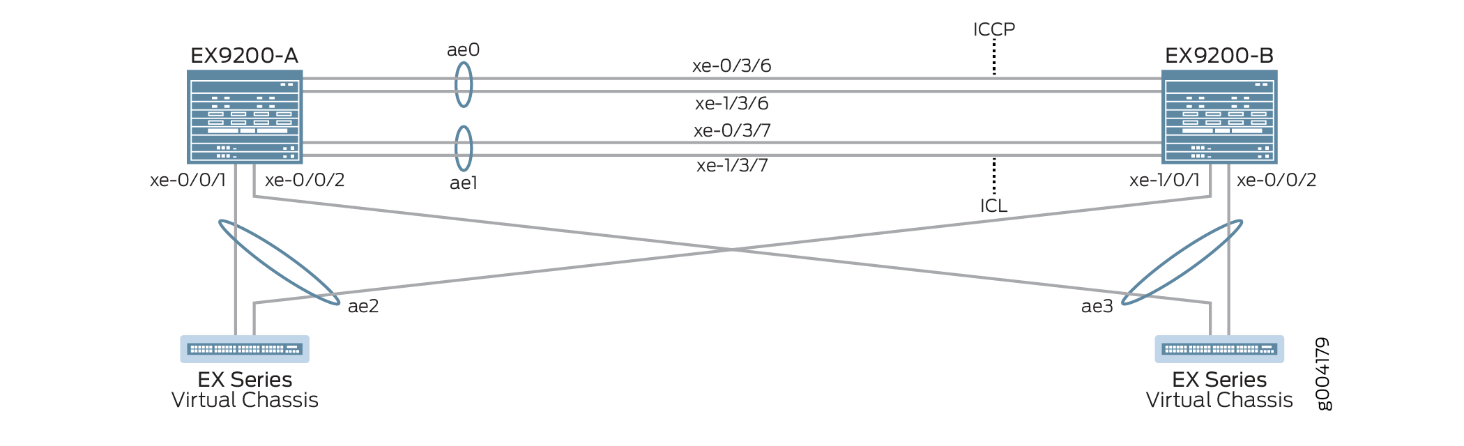
표 2에는 이 구성 예에서 사용되는 토폴로지가 자세히 나와 있습니다.
| 호스트 이름 | 기본 하드웨어 | 다중 섀시 링크 어그리게이션 그룹 |
|---|---|---|
| EX9200-A EX9200-B |
EX9200 EX9200 |
ae0은 어그리게이션 이더넷 인터페이스로 구성되며 ICCP 링크로 사용되며 다음 인터페이스는 ae0 의 일부입니다: xe-0/3/6 및 xe-1/3/6. ae1은 어그리게이션 이더넷 인터페이스로 구성되며 ICL 링크로 사용되며, xe-0/3/7 및 xe-1/3/7 인터페이스가 ae1의 일부입니다. ae2는 MC-LAG로 구성되며, 스위치 B의 xe-0/0/1 및 스위치 A의 xe-1/0/1 인터페이스가 ae2의 일부입니다. ae3는 MC-LAG로 구성되며, 다음 인터페이스는 스위치 A와 스위치 B 모두에서 ae3의 일부입니다: xe-0/0/2. |
| Virtual Chassis Virtual Chassis |
해당 사항 없음. Virtual Chassis는 설명 목적으로만 표시됩니다. |
Virtual Chassis는 LAG 인터페이스를 통해 두 개의 EX9200 스위치에 연결됩니다. Virtual Chassis 구성은 이 예에 포함되지 않으며 샘플 토폴로지를 설명하기 위해서만 표시됩니다. |
구성
CLI 빠른 구성
이 예를 빠르게 구성하려면, 아래 명령을 복사하여 텍스트 파일에 붙여 넣은 다음 모든 라인브레이크를 제거하고, 네트워크 구성을 일치하는 데 필요한 세부 사항을 변경하고, 계층 수준에서 [edit] 명령을 복사하여 CLI에 붙여 넣은 다음, 구성 모드에서 입력합니다 commit .
EX9200-A
set system login user MCLAG_Admin uid 2000 set system login user MCLAG_Admin class super-user set system login user MCLAG_Admin authentication encrypted-password "$ABC123" set system static-host-mapping EX9200-A inet 10.92.76.2 set system static-host-mapping EX9200-B inet 10.92.76.4 set system services netconf ssh set system commit peers-synchronize set system commit peers EX9200-B user MCLAG_Admin set system commit peers EX9200-B authentication "$ABC123" set interfaces irb unit 100 family inet address 192.168.100.2/24 arp 192.168.100.3 l2-interface ae1 set interfaces irb unit 100 family inet address 192.168.100.2/24 arp 192.168.100.3 mac 28:8a:1c:e5:3b:f0 set interfaces irb unit 100 family inet address 192.168.100.2/24 vrrp-group 1 virtual-address 192.168.100.1 set interfaces irb unit 100 family inet address 192.168.100.2/24 vrrp-group 1 priority 150 set interfaces irb unit 100 family inet address 192.168.100.2/24 vrrp-group 1 accept-data set interfaces lo0 unit 0 family inet address 172.16.32.5/32 set routing-options static route 0.0.0.0/0 next-hop 10.92.77.254 set protocols ospf area 0.0.0.0 interface lo0.0 passive set protocols ospf area 0.0.0.0 interface ae0.0 set protocols lldp interface all set chassis aggregated-devices ethernet device-count 20 set groups MC_Config_Global set groups MC_Config_Global when peers EX9200-A set groups MC_Config_Global when peers EX9200-B set groups MC_Config_Global interfaces xe-0/3/6 ether-options 802.3ad ae0 set groups MC_Config_Global interfaces xe-1/3/6 ether-options 802.3ad ae0 set groups MC_Config_Global interfaces ae0 description "ICCP Layer 3 Link with 2 members,xe-0/3/6,xe-1/3/6" set groups MC_Config_Global interfaces ae0 aggregated-ether-options lacp active set groups MC_Config_Global interfaces ae0 aggregated-ether-options lacp periodic fast set groups MC_Config_Global interfaces ae0 aggregated-ether-options lacp system-id 00:01:02:03:04:05 set groups MC_Config_Global interfaces ae0 aggregated-ether-options lacp admin-key 0 set groups MC_Config_Global interfaces xe-0/3/7 ether-options 802.3ad ae1 set groups MC_Config_Global interfaces xe-1/3/7 ether-options 802.3ad ae1 set groups MC_Config_Global interfaces ae1 description "ICL Layer 2 link with 2 members,xe-0/3/7,1/3/7" set groups MC_Config_Global interfaces ae1 unit 0 family ethernet-switching interface-mode trunk set groups MC_Config_Global interfaces ae1 unit 0 family ethernet-switching vlan members all set groups MC_Config_Global interfaces ae1 vlan-tagging set groups MC_Config_Global interfaces ae1 aggregated-ether-options lacp active set groups MC_Config_Global interfaces ae1 aggregated-ether-options lacp periodic fast set groups MC_Config_Global interfaces ae1 aggregated-ether-options lacp system-id 00:01:02:03:04:06 set groups MC_Config_Global interfaces ae1 aggregated-ether-options lacp admin-key 1 set groups MC_Config_Global interfaces xe-0/0/1 ether-options 802.3ad ae2 set groups MC_Config_Global interfaces xe-1/0/1 ether-options 802.3ad ae2 set groups MC_Config_Global interfaces ae2 unit 0 description “MC-LAG interface with members xe-0/0/1,xe-1/0/1” set groups MC_Config_Global interfaces ae2 unit 0 family ethernet-switching interface-mode trunk set groups MC_Config_Global interfaces ae2 unit 0 family ethernet-switching vlan members all set groups MC_Config_Global interfaces ae2 aggregated-ether-options lacp active set groups MC_Config_Global interfaces ae2 aggregated-ether-options lacp periodic fast set groups MC_Config_Global interfaces ae2 aggregated-ether-options lacp system-id 00:01:02:03:04:07 set groups MC_Config_Global interfaces ae2 aggregated-ether-options lacp admin-key 2 set groups MC_Config_Global interfaces ae2 aggregated-ether-options mc-ae mc-ae-id 2 set groups MC_Config_Global interfaces ae2 aggregated-ether-options mc-ae redundancy-group 1 set groups MC_Config_Global interfaces ae2 aggregated-ether-options mc-ae mode active-active set groups MC_Config_Global interfaces ae2 aggregated-ether-options mc-ae init-delay-time 520 set groups MC_Config_Global interfaces ae2 aggregated-ether-options mc-ae events iccp-peer-down prefer-status-control-active set groups MC_Config_Global interfaces xe-0/0/2 ether-options 802.3ad ae3 set groups MC_Config_Global interfaces ae3 unit 0 description “MC-LAG interface with members xe-0/0/2 on both switches” set groups MC_Config_Global interfaces ae3 unit 0 family ethernet-switching interface-mode trunk set groups MC_Config_Global interfaces ae3 unit 0 family ethernet-switching vlan members all set groups MC_Config_Global interfaces ae3 aggregated-ether-options lacp active set groups MC_Config_Global interfaces ae3 aggregated-ether-options lacp periodic fast set groups MC_Config_Global interfaces ae3 aggregated-ether-options lacp system-id 00:01:02:03:04:08 set groups MC_Config_Global interfaces ae3 aggregated-ether-options lacp admin-key 3 set groups MC_Config_Global interfaces ae3 aggregated-ether-options mc-ae mc-ae-id 3 set groups MC_Config_Global interfaces ae3 aggregated-ether-options mc-ae redundancy-group 1 set groups MC_Config_Global interfaces ae3 aggregated-ether-options mc-ae mode active-active set groups MC_Config_Global interfaces ae3 aggregated-ether-options mc-ae init-delay-time 520 set groups MC_Config_Global interfaces ae3 aggregated-ether-options mc-ae events iccp-peer-down prefer-status-control-active set groups MC_Config_Global vlans v100 vlan-id 100 set groups MC_Config_Global vlans v100 l3-interface irb.100 set groups MC_Config_Global multi-chassis mc-lag consistency-check set groups MC_Config_Global protocols rstp interface ae2 set groups MC_Config_Global protocols rstp interface ae3 set groups MC_Config_Global protocols rstp bridge-priority 0 set groups MC_Config_Global protocols rstp system-id 00:01:02:03:04:09 set groups MC_Config_Global switch-options service-id 1 set groups MC_Config_Local set groups MC_Config_Local interfaces ae0 unit 0 family inet address 172.16.32.9/30 set groups MC_Config_Local interfaces ae2 aggregated-ether-options mc-ae chassis-id 0 set groups MC_Config_Local interfaces ae2 aggregated-ether-options mc-ae status-control active set groups MC_Config_Local interfaces ae3 aggregated-ether-options mc-ae chassis-id 0 set groups MC_Config_Local interfaces ae3 aggregated-ether-options mc-ae status-control active set groups MC_Config_Remote set groups MC_Config_Remote interfaces ae0 unit 0 family inet address 172.16.32.10/30 set groups MC_Config_Remote interfaces ae2 aggregated-ether-options mc-ae chassis-id 1 set groups MC_Config_Remote interfaces ae2 aggregated-ether-options mc-ae status-control standby set groups MC_Config_Remote interfaces ae3 aggregated-ether-options mc-ae chassis-id 1 set groups MC_Config_Remote interfaces ae3 aggregated-ether-options mc-ae status-control standby set interfaces ae2 unit 0 multi-chassis-protection 172.16.32.6 interface ae1 set interfaces ae3 unit 0 multi-chassis-protection 172.16.32.6 interface ae1 set protocols iccp local-ip-addr 172.16.32.5 set protocols iccp peer 172.16.32.6 session-establishment-hold-time 50 set protocols iccp peer 172.16.32.6 redundancy-group-id-list 1 set protocols iccp peer 172.16.32.6 backup-liveness-detection backup-peer-ip 10.92.76.4 set protocols iccp peer 172.16.32.6 liveness-detection minimum-interval 2000 set protocols iccp peer 172.16.32.6 liveness-detection multiplier 4 set multi-chassis multi-chassis-protection 172.16.32.6 interface ae1 set apply-groups [ MC_Config_Global MC_Config_Local MC_Config_Remote ]
EX9200-B
set system login user MCLAG_Admin uid 2000 set system login user MCLAG_Admin class super-user set system login user MCLAG_Admin authentication encrypted-password "$ABC123" set system static-host-mapping EX9200-A inet 10.92.76.2 set system static-host-mapping EX9200-B inet 10.92.76.4 set system services netconf ssh set system commit peers-synchronize set system commit peers EX9200-A user MCLAG_Admin set system commit peers EX9200-A authentication "$ABC123" set interfaces irb unit 100 family inet address 192.168.100.3/24 arp 192.168.100.2 l2-interface ae1 set interfaces irb unit 100 family inet address 192.168.100.3/24 arp 192.168.100.2 mac 28:8a:1c:e3:f7:f0 set interfaces irb unit 100 family inet address 192.168.100.3/24 vrrp-group 1 virtual-address 192.168.100.1 set interfaces irb unit 100 family inet address 192.168.100.3/24 vrrp-group 1 priority 100 set interfaces irb unit 100 family inet address 192.168.100.3/24 vrrp-group 1 accept-data set interfaces lo0 unit 0 family inet address 172.16.32.6/32 set routing-options static route 0.0.0.0/0 next-hop 10.92.77.254 set protocols ospf area 0.0.0.0 interface lo0 passive set protocols ospf area 0.0.0.0 interface ae0 set protocols lldp interface all set chassis aggregated-devices ethernet device-count 20 set interfaces ae2 unit 0 multi-chassis-protection 172.16.32.5 interface ae1 set interfaces ae3 unit 0 multi-chassis-protection 172.16.32.5 interface ae1 set protocols iccp local-ip-addr 172.16.32.6 set protocols iccp peer 172.16.32.5 session-establishment-hold-time 50 set protocols iccp peer 172.16.32.5 redundancy-group-id-list 1 set protocols iccp peer 172.16.32.5 backup-liveness-detection backup-peer-ip 10.92.76.2 set protocols iccp peer 172.16.32.5 liveness-detection minimum-interval 2000 set protocols iccp peer 172.16.32.5 liveness-detection multiplier 4 set apply-groups [ MC_Config_Global MC_Config_Local MC_Config_Remote ]
EX9200-A에서 MC-LAG 구성
단계별 절차
다음 예에서는 구성 계층에서 다양한 수준을 탐색해야 합니다.
-
사용자 식별자(UID), 로그인 클래스 및 비밀번호와 함께 스위치에 액세스할 수 있는 사용자 계정을 생성합니다.
[edit system] user@EX9200-A# set login user MCLAG_Admin uid 2000 user@EX9200-A# set login user MCLAG_Admin class super-user user@EX9200-A# set login user MCLAG_Admin authentication encrypted-password “$ABC123”
-
EX9200-A를 10.92.76.2로, EX9200-B를 10.92.76.4로 정적으로 매핑합니다.
[edit system] user@EX9200-A# set static-host-mapping EX9200-A inet 10.92.76.2 user@EX9200-A# set static-host-mapping EX9200-B inet 10.92.76.4
-
SSH를 사용하여 NETCONF 서비스를 활성화합니다.
[edit system] user@EX9200-A# set services netconf ssh
-
기본적으로 EX9200-A에서 EX9200-B로 MC-LAG 구성을 복사하고 로드하도록 명령문을 활성화
peers-synchronize합니다.[edit system] user@EX9200-A# set commit peers-synchronize
-
EX9200-A가 MC-LAG 구성을 동기화할 피어인 EX9200-B의 호스트 이름, 사용자 이름 및 인증 세부 정보를 구성합니다.
[edit system] user@EX9200-A# set commit peers EX9200-B user MCLAG_Admin user@EX9200-A# set commit peers EX9200-B user authentication “$ABC123”
-
라우팅 프로토콜이 IRB 인터페이스를 통과할 수 있도록 MC-LAG IRB 피어에서 MC-LAG IRB 피어에서 MC-LAG IRB 및 정적 ARP(주소 결정 프로토콜)를 구성합니다.
[edit interfaces] user@EX9200-A# set irb unit 100 family inet address 192.168.100.2/24 arp 192.168.100.3 l2-interface ae1 user@EX9200-A# set irb unit 100 family inet address 192.168.100.2/24 arp 192.168.100.3 mac 28:8a:1c:e5:3b:f0
-
VRRP 그룹의 각 스위치 간에 공유되는 가상 IP 주소를 할당하고 VRRP 그룹의 각 개별 멤버에 대한 개별 IP 주소를 할당하여 MC-LAG에서 VRRP를 활성화합니다.
[edit interfaces] user@EX9200-A# set irb unit 100 family inet address 192.168.100.2/24 vrrp-group 1 virtual-address 192.168.100.1 user@EX9200-A# set irb unit 100 family inet address 192.168.100.2/24 vrrp-group 1 priority 150 user@EX9200-A# set irb unit 100 family inet address 192.168.100.2/24 vrrp-group 1 accept-data
-
루프백 인터페이스를 구성합니다.
[edit interfaces] user@EX9200-A# set lo0 unit 0 family inet address 172.16.32.5/32
-
기본 게이트웨이를 구성합니다.
[edit routing-options] user@EX9200-A# set static route 0.0.0.0 next-hop 10.92.77.254
-
루프백 인터페이스와 ICCP 인터페이스를 포함하는 OSPF 영역을 구성합니다.
[edit protocols] user@EX9200-A# set ospf area 0.0.0.0 interface lo0 passive user@EX9200-A# set ospf area 0.0.0.0 interface ae0
-
모든 인터페이스에 대해 링크 레이어 디스커버리 프로토콜을 구성합니다.
[edit protocols] user@EX9200-A# set lldp interface all
-
EX9200-A에서 생성할 어그리게이션 이더넷 인터페이스의 수를 구성합니다.
[edit chassis] user@EX9200-A# set aggregated-devices ethernet device-count 20
-
EX9200-A 및 EX9200-B 모두에 적용되는 글로벌 MC-LAG 구성을 위한 구성 그룹을 구성합니다.
글로벌 구성은 EX9200-A와 EX9200-B 간에 동기화됩니다.
[edit groups] user@EX9200-A# set MC_Config_Global
-
MC_Config_Global 구성 그룹을 적용할 피어를 지정합니다.
[edit groups] user@EX9200-A# set MC_Config_Global when peers EX9200-A user@EX9200-A# set MC_Config_Global when peers EX9200-B
-
ICCP(Inter-Chassis Control Protocol) 인터페이스에 사용될 어그리게이션 이더넷 인터페이스에 멤버 인터페이스를 추가합니다.
[edit groups] user@EX9200-A# set MC_Config_Global interfaces xe-0/3/6 ether-options 802.3ad ae0 user@EX9200-A# set MC_Config_Global interfaces xe-1/3/6 ether-options 802.3ad ae0
-
ICCP(Inter-Chassis Control Protocol) 인터페이스에 사용될 어그리게이션 이더넷 인터페이스(ae0)를 구성합니다.
참고:이후 단계에서 ae0의 IP 주소를 구성할 것입니다.
[edit groups] user@EX9200-A# set MC_Config_Global interfaces ae0 description "ICCP Layer 3 Link with 2 members,xe-0/3/6,xe-1/3/6"
-
ae0에서 LACP 매개 변수를 구성합니다.
[edit groups] user@EX9200-A# set MC_Config_Global interfaces ae0 aggregated-ether-options lacp active user@EX9200-A# set MC_Config_Global interfaces ae0 aggregated-ether-options lacp periodic fast
-
ae0에서 LACP 시스템 ID를 구성합니다.
[edit groups] user@EX9200-A# set MC_Config_Global interfaces ae0 aggregated-ether-options lacp system-id 00:01:02:03:04:05
-
ae0에서 LACP 관리 키를 구성합니다.
[edit groups] user@EX9200-A# set MC_Config_Global interfaces ae0 aggregated-ether-options lacp admin-key 0
-
ICL에 사용될 어그리게이션 이더넷 인터페이스(ae1)에 멤버 인터페이스를 추가합니다.
[edit groups] user@EX9200-A# set MC_Config_Global interfaces xe-0/3/7 ether-options 802.3ad ae1 user@EX9200-A# set MC_Config_Global interfaces xe-1/3/7 ether-options 802.3ad ae1
-
ICL에 사용할 어그리게이션 이더넷 인터페이스를 구성합니다.
[edit groups] user@EX9200-A# set MC_Config_Global interfaces ae1 description "ICL Layer 2 link with 2 members,xe-0/3/7,1/3/7"
-
ae1을 레이어 2 인터페이스로 구성합니다.
[edit groups] user@EX9200-A# set MC_Config_Global ae1 unit 0 family ethernet-switching interface-mode trunk user@EX9200-A# set MC_Config_Global ae1 unit 0 family ethernet-switching vlan members all
-
ae1에서 802.1Q VLAN 태그가 지정된 프레임의 수신 및 전송을 활성화합니다.
[edit groups] user@EX9200-A# set MC_Config_Global interfaces ae1 vlan-tagging
-
ae1에서 LACP 매개 변수를 구성합니다.
[edit groups] user@EX9200-A# set MC_Config_Global interfaces ae1 aggregated-ether-options lacp active user@EX9200-A# set MC_Config_Global interfaces ae1 aggregated-ether-options lacp periodic fast
-
ae1에서 LACP 시스템 ID를 구성합니다.
[edit groups] user@EX9200-A# set MC_Config_Global interfaces ae1 aggregated-ether-options lacp system-id 00:01:02:03:04:06
-
ae1에서 LACP 관리 키를 구성합니다.
[edit groups] user@EX9200-A# set MC_Config_Global interfaces ae1 aggregated-ether-options lacp admin-key 1
-
MC-LAG 인터페이스로 사용될 어그리게이션 이더넷 인터페이스(ae2)에 멤버 인터페이스를 추가합니다.
[edit groups] user@EX9200-A# set MC_Config_Global interfaces xe-0/0/1 ether-options 802.3ad ae2 user@EX9200-A# set MC_Config_Global interfaces xe-1/0/1 ether-options 802.3ad ae2
-
MC-LAG 인터페이스로 사용될 어그리게이션 이더넷 인터페이스(ae2)를 구성합니다.
[edit groups] user@EX9200-A# set MC_Config_Global interfaces ae2 description “MC-LAG interface with members xe-0/0/1,xe-1/0/1”
-
ae2를 레이어 2 인터페이스로 구성합니다.
[edit groups] user@EX9200-A# set MC_Config_Global interfaces ae2 unit 0 family ethernet-switching interface-mode trunk user@EX9200-A# set MC_Config_Global interfaces ae2 unit 0 family ethernet-switching vlan members all
-
ae2에서 LACP 매개 변수를 구성합니다.
[edit groups] user@EX9200-A# set MC_Config_Global interfaces ae2 aggregated-ether-options lacp active user@EX9200-A# set MC_Config_Global interfaces ae2 aggregated-ether-options lacp periodic fast
-
ae2에서 LACP 시스템 ID를 구성합니다.
[edit groups] user@EX9200-A# set MC_Config_Global interfaces ae2 aggregated-ether-options lacp system-id 00:01:02:03:04:07
-
ae2에서 LACP 관리 키를 구성합니다.
[edit groups] user@EX9200-A# set MC_Config_Global interfaces ae2 aggregated-ether-options lacp admin-key 2
-
ae2에서 MC-AE 인터페이스 속성을 구성합니다.
[edit groups] user@EX9200-A# set MC_Config_Global interfaces ae2 aggregated-ether-options mc-ae mc-ae-id 2 user@EX9200-A# set MC_Config_Global interfaces ae2 aggregated-ether-options mc-ae redundancy-group 1
-
ae2의 모드를 액티브-액티브로 지정합니다.
[edit groups] user@EX9200-A# set MC_Config_Global interfaces ae2 aggregated-ether-options mc-ae mode active-active
-
MC-LAG 피어를 재부팅한 후 MC-AE 인터페이스를 가동 상태로 전환하는 것을 지연하는 시간을 초 단위로 지정합니다.
프로토콜 컨버전스 이후까지 인터페이스 가동을 지연시킴으로써, 장애가 발생한 링크 및 디바이스를 복구하는 동안 패킷 손실을 방지할 수 있습니다. 이 네트워크 구성 예는 520초의 지연 시간을 사용합니다. 이 지연 시간은 네트워크에 최적화되지 않을 수 있으므로 네트워크 요구 사항에 맞게 조정해야 합니다.
[edit groups] user@EX9200-A# set MC_Config_Global interfaces ae2 aggregated-ether-options mc-ae init-delay-time 520
-
MC-LAG 그룹의 피어가 다운되면 status-control active로 구성된 피어가 활성 피어가 되도록 지정합니다.
[edit groups] user@EX9200-A# set MC_Config_Global interfaces ae2 aggregated-ether-options mc-ae events iccp-peer-down prefer-status-control-active
-
MC-LAG 인터페이스로 사용될 어그리게이션 이더넷 인터페이스(ae3)에 멤버 인터페이스를 추가합니다.
참고:EX9200-B는 동일한 인터페이스 이름 xe-0/0/2를 사용합니다.
[edit groups] user@EX9200-A# set MC_Config_Global interfaces xe-0/0/2 ether-options 802.3ad ae3
-
MC-LAG 인터페이스로 사용될 어그리게이션 이더넷 인터페이스(ae3)를 구성합니다.
[edit groups] user@EX9200-A# set groups MC_Config_Global interfaces ae3 description “MC-LAG interface with members xe-0/0/2 on both switches”
-
ae3를 레이어 2 인터페이스로 구성합니다.
[edit groups] user@EX9200-A# set MC_Config_Global interfaces ae3 unit 0 family ethernet-switching interface-mode trunk user@EX9200-A# set MC_Config_Global interfaces ae3 unit 0 family ethernet-switching vlan members all
-
ae3에서 LACP 매개 변수를 구성합니다.
[edit groups] user@EX9200-A# set MC_Config_Global interfaces ae3 aggregated-ether-options lacp active user@EX9200-A# set MC_Config_Global interfaces ae3 aggregated-ether-options lacp periodic fast
-
ae3에서 LACP 시스템 ID를 구성합니다.
[edit groups] user@EX9200-A# set MC_Config_Global interfaces ae3 aggregated-ether-options lacp system-id 00:01:02:03:04:08
-
ae3에서 LACP 관리 키를 구성합니다.
[edit groups] user@EX9200-A# set MC_Config_Global interfaces ae3 aggregated-ether-options lacp admin-key 3
-
ae3에서 MC-AE 인터페이스 속성을 구성합니다.
[edit groups] user@EX9200-A# set MC_Config_Global interfaces ae3 aggregated-ether-options mc-ae mc-ae-id 3 user@EX9200-A# set MC_Config_Global interfaces ae3 aggregated-ether-options mc-ae redundancy-group 1
-
ae3의 모드를 액티브-액티브로 지정합니다.
[edit groups] user@EX9200-A# set MC_Config_Global interfaces ae3 aggregated-ether-options mc-ae mode active-active
-
MC-LAG 피어를 재부팅한 후 MC-AE 인터페이스를 가동 상태로 전환하는 것을 지연하는 시간을 초 단위로 지정합니다.
프로토콜 컨버전스 이후까지 인터페이스 가동을 지연시킴으로써, 장애가 발생한 링크 및 디바이스를 복구하는 동안 패킷 손실을 방지할 수 있습니다. 이 네트워크 구성 예는 520초의 지연 시간을 사용합니다. 이 지연 시간은 네트워크에 최적화되지 않을 수 있으므로 네트워크 요구 사항에 맞게 조정해야 합니다.
[edit groups] user@EX9200-A# set MC_Config_Global interfaces ae3 aggregated-ether-options mc-ae init-delay-time 520
-
MC-LAG 그룹의 피어가 다운되면 status-control active로 구성된 피어가 활성 피어가 되도록 지정합니다.
[edit groups] user@EX9200-A# set MC_Config_Global interfaces ae3 aggregated-ether-options mc-ae events iccp-peer-down prefer-status-control-active
-
최종 사용자를 연결하도록 VLAN 100을 구성합니다.
[edit groups] user@EX9200-A# set MC_Config_Global vlans v100 vlan-id 100
-
VLAN 100에 대해 라우팅된 VLAN 인터페이스를 구성합니다.
[edit groups] user@EX9200-A# set MC_Config_Global vlans v100 l3-interface irb.100
-
일관성 검사를 사용하도록 설정합니다.
[edit groups] user@EX9200-A# set MC_Config_Global multi-chassis mc-lag consistency-check
-
선택적 루프 방지를 위해 ae2 및 ae3 인터페이스(MC-LAG 인터페이스)에서 빠른 스패닝 트리 프로토콜을 활성화합니다.
[edit groups] user@EX9200-A# set MC_Config_Global protocols rstp interfaces ae2 user@EX9200-A# set MC_Config_Global protocols rstp interfaces ae3
-
RSTP 브리지 우선 순위를 구성합니다.
브리지 우선 순위를 0으로 설정하면 EX9200-A 및 EX9200-B의 MC-AE 노드가 최고의 우선 순위가 됩니다.
[edit groups] user@EX9200-A# set MC_Config_Global protocols rstp bridge-priority 0
-
RSTP 시스템 식별자 값을 구성합니다.
[edit groups] user@EX9200-A# set MC_Config_Global protocols rstp system-id 00:01:02:03:04:09
-
스위치 서비스 ID를 지정합니다.
스위치 서비스 ID는 MC-LAG 멤버 간에 애플리케이션, ARP 및 MAC 학습을 동기화하는 데 사용됩니다.
[edit groups] user@EX9200-A# set MC_Config_Global switch-options service-id 1
-
로컬 피어에 적용되는 MC-LAG 구성에 대한 구성 그룹을 구성합니다.
[edit groups] user@EX9200-A# set MC_Config_Local
-
ICCP 인터페이스(ae0)를 레이어 3 인터페이스로 구성합니다.
[edit groups] user@EX9200-A# set MC_Config_Local interfaces ae0 unit 0 family inet address 172.16.32.9/30
-
어그리게이션 이더넷 인터페이스가 속한 MC-LAG(ae2)에 대한 고유한 섀시 ID를 지정합니다.
[edit groups] user@EX9200-A# set MC_Config_Local interfaces ae2 aggregated-ether-options mc-ae chassis-id 0
-
ae2의 status-control 설정을 활성화하도록 지정합니다.
[edit groups] user@EX9200-A# set MC_Config_Local interfaces ae2 aggregated-ether-options mc-ae status-control active
-
어그리게이션 이더넷 인터페이스가 속한 MC-LAG(ae3)에 대한 고유한 섀시 ID를 지정합니다.
[edit groups] user@EX9200-A# set MC_Config_Local interfaces ae3 aggregated-ether-options mc-ae chassis-id 0
-
ae3의 status-control 설정을 활성화하도록 지정합니다.
[edit groups] user@EX9200-A# set MC_Config_Local interfaces ae3 aggregated-ether-options mc-ae status-control active
-
원격 피어에 적용되는 MC-LAG 구성에 대한 구성 그룹을 구성합니다.
[edit groups] user@EX9200-A# set MC_Config_Remote
-
ae0을 레이어 3 인터페이스로 구성합니다.
[edit groups] user@EX9200-A# set MC_Config_Remote interfaces ae0 unit 0 family inet address 172.16.32.10/30
-
어그리게이션 이더넷 인터페이스가 속한 MC-LAG(ae2)에 대한 고유한 섀시 ID를 지정합니다.
[edit groups] user@EX9200-A# set MC_Config_Remote interfaces ae2 aggregated-ether-options mc-ae chassis-id 1
-
대기할 ae2의 status-control 설정을 지정합니다.
[edit groups] user@EX9200-A# set MC_Config_Remote interfaces ae2 aggregated-ether-options mc-ae status-control standby
-
어그리게이션 이더넷 인터페이스가 속한 MC-LAG(ae3)에 대한 고유한 섀시 ID를 지정합니다.
[edit groups] user@EX9200-A# set MC_Config_Remote interfaces ae3 aggregated-ether-options mc-ae chassis-id 1
-
대기할 ae3의 status-control 설정을 지정합니다.
[edit interfaces] user@EX9200-A# set MC_Config_Remote interfaces ae3 aggregated-ether-options mc-ae status-control standby
-
MC-LAG 그룹의 피어가 다운되면 status-control active로 구성된 피어가 활성 피어가 되도록 지정합니다.
[edit interfaces] user@EX9200-A# set MC_Config_Remote interfaces ae3 aggregated-ether-options mc-ae events iccp-peer-down prefer-status-control-standby
-
두 MC-LAG 피어 간의 링크 보호를 활성화합니다.
장애 발생 시 MC-AE 인터페이스, ae2 및 ae3를 보호하기 위해 ICL 역할을 하도록 인터페이스 ae1을 할당합니다.
[edit interfaces] user@EX9200-A# set ae2 unit 0 multi-chassis-protection 172.16.32.6 interface ae1
user@EX9200-A# set ae3 unit 0 multi-chassis-protection 172.16.32.6 interface ae1
-
ICCP 인터페이스의 로컬 IP 주소를 지정합니다.
[edit protocols] user@EX9200-A# set iccp local-ip-addr 172.16.32.5
-
ICCP가 더 빠르게 연결되도록 세션 설정 보류 시간을 구성합니다.
참고:세션 설정 보류 시간 값으로 50초를 권장합니다.
[edit protocols] user@EX9200-A# set iccp peer 172.16.32.6 session-establishment-hold-time 50 user@EX9200-A# set iccp peer 172.16.32.6 redundancy-group-id-list 1 user@EX9200-A# set iccp peer 172.16.32.6 backup-liveness-detection backup-peer-ip 10.92.76.4
-
ICCP에 대한 BFD를 활성화하려면 최소 수신 간격을 구성합니다.
최소 수신 간격 값은 6초로 설정하는 것이 좋습니다.
[edit protocols] user@EX9200-A# set iccp peer 172.16.32.6 liveness-detection minimum-interval 2000 user@EX9200-A# set iccp peer 172.16.32.6 liveness-detection multiplier 4
-
Junos 구성이 MC_Config_Global, MC_Config_Local, MC_Config_Remote 구성 그룹의 문을 상속하도록 앞서 구성한 그룹을 적용합니다.
[edit] user@EX9200-A# set apply-groups [ MC_Config_Global MC_Config_Local MC_Config_Remote ]
EX9200-B에서 MC-LAG 구성
단계별 절차
다음 예에서는 구성 계층에서 다양한 수준을 탐색해야 합니다.
-
사용자 식별자(UID), 로그인 클래스 및 비밀번호와 함께 스위치에 액세스할 수 있는 사용자 계정을 생성합니다.
[edit system] user@EX9200-A# set login user MCLAG_Admin uid 2000 user@EX9200-B# set login user MCLAG_Admin class super-user user@EX9200-B# set login user MCLAG_Admin authentication encrypted-password “$ABC123”
-
EX9200-A를 10.92.76.2로, EX9200-B를 10.92.76.4로 정적으로 매핑합니다.
[edit system] user@EX9200-B# set static-host-mapping EX9200-A inet 10.92.76.2 user@EX9200-B# set static-host-mapping EX9200-B inet 10.92.76.4
-
SSH를 사용하여 NETCONF 서비스를 활성화합니다.
[edit system] user@EX9200-B# set services netconf ssh
-
기본적으로 EX9200-B에서 EX9200-A로 MC-LAG 구성을 복사하고 로드하려면 문을 활성화
peers-synchronize합니다.[edit system] user@EX9200-B# set commit peers-synchronize
-
EX9200-B가 MC-LAG 구성을 동기화할 피어인 EX9200-A의 호스트 이름, 사용자 이름 및 인증 세부 정보를 구성합니다.
[edit system] user@EX9200-B# set commit peers EX9200-A user MCLAG_Admin user@EX9200-A# set commit peers EX9200-A authentication "$ABC123"
-
라우팅 프로토콜이 IRB 인터페이스를 통과할 수 있도록 MC-LAG IRB 피어에서 MC-LAG IRB 피어에서 MC-LAG IRB 및 정적 ARP(주소 결정 프로토콜)를 구성합니다.
[edit interfaces] user@EX9200-B# set irb unit 100 family inet address 192.168.100.3/24 arp 192.168.100.2 l2-interface ae1 user@EX9200-B# set irb unit 100 family inet address 192.168.100.3/24 arp 192.168.100.2 mac 28:8a:1c:e3:f7:f0
-
VRRP 그룹의 각 스위치 간에 공유되는 가상 IP 주소를 할당하고 VRRP 그룹의 각 개별 멤버에 대한 개별 IP 주소를 할당하여 MC-LAG에서 VRRP를 활성화합니다.
[edit interfaces] user@EX9200-B# set irb unit 100 family inet address 192.168.100.3/24 vrrp-group 1 virtual-address 192.168.100.1 user@EX9200-B# set irb unit 100 family inet address 192.168.100.3/24 vrrp-group 1 priority 100 user@EX9200-B# set irb unit 100 family inet address 192.168.100.3/24 vrrp-group 1 accept-data
-
루프백 인터페이스를 구성합니다.
[edit interfaces] user@EX9200-B# set lo0 unit 0 family inet address 172.16.32.6/32
-
기본 게이트웨이를 구성합니다.
[edit routing-options] user@EX9200-B# set static route 0.0.0.0 next-hop 10.92.77.254
-
루프백 인터페이스와 ICCP 인터페이스를 포함하는 OSPF 영역을 구성합니다.
[edit protocols] user@EX9200-B# set ospf area 0.0.0.0 interface lo0 passive user@EX9200-B# set ospf area 0.0.0.0 interface ae0
-
모든 인터페이스에 대해 링크 레이어 디스커버리 프로토콜을 구성합니다.
[edit protocols] user@EX9200-B# set lldp interface all
-
EX9200-B에서 생성할 어그리게이션 이더넷 인터페이스의 수를 구성합니다.
[edit chassis] user@EX9200-B# set aggregated-devices ethernet device-count 20
-
두 MC-LAG 피어 간의 링크 보호를 활성화합니다.
장애 발생 시 MC-AE 인터페이스, ae2 및 ae3를 보호하기 위해 ICL 역할을 하도록 인터페이스 ae1을 할당합니다.
[edit interfaces] user@EX9200-B# set ae2 unit 0 multi-chassis-protection 172.16.32.5 interface ae1 user@EX9200-B# set ae3 unit 0 multi-chassis-protection 172.16.32.5 interface ae1
-
ICCP 인터페이스의 로컬 IP 주소를 지정합니다.
[edit protocols] user@EX9200-B# set iccp local-ip-addr 172.16.32.6
-
ICCP가 더 빠르게 연결되도록 세션 설정 보류 시간을 구성합니다.
참고:세션 설정 보류 시간 값으로 50초를 권장합니다.
[edit protocols] user@EX9200-B# set iccp peer 172.16.32.5 session-establishment-hold-time 50 user@EX9200-B# set iccp peer 172.16.32.5 redundancy-group-id-list 1 user@EX9200-B# set iccp peer 172.16.32.5 backup-liveness-detection backup-peer-ip 10.92.76.2
-
ICCP에 대한 BFD를 활성화하려면 최소 수신 간격을 구성합니다.
최소 수신 간격 값은 6초로 설정하는 것이 좋습니다.
[edit protocols] user@EX9200-B# set iccp peer 172.16.32.5 liveness-detection minimum-interval 2000 user@EX9200-B# set iccp peer 172.16.32.5 liveness-detection multiplier 4
-
Junos 구성이 MC_Config_Global, MC_Config_Local, MC_Config_Remote 구성 그룹의 문을 상속하도록 앞서 구성한 그룹을 적용합니다.
[edit] user@EX9200-B# set apply-groups [ MC_Config_Global MC_Config_Local MC_Config_Remote ]
결과
구성을 커밋하기 전에 EX9200-A에 구성 결과를 표시합니다.
user@EX9200-A# show system services
netconf {
ssh;
}
user@EX9200-A# show system commit
peers-synchronize;
peers {
EX9200-B {
user MCLAG_Admin;
authentication "$ABC123”;
}
}
}
user@EX9200-A# show interfaces
ae2 {
unit 0 {
multi-chassis-protection 172.16.32.6 {
interface ae1;
}
}
}
ae3 {
unit 0 {
multi-chassis-protection 172.16.32.6 {
interface ae1;
}
}
}
irb {
unit 100 {
family inet {
address 192.168.100.2/24 {
arp 192.168.100.3 l2-interface ae1.0 mac 28:8a:1c:e5:3b:f0;
vrrp-group 1 {
virtual-address 192.168.100.1;
priority 150;
accept-data;
}
}
}
}
}
lo0 {
unit 0 {
family inet {
address 172.16.32.5/32;
}
}
}
user@EX9200-A# show routing-options
static {
route 0.0.0.0/0 next-hop 10.92.77.254;
}
user@EX9200-A# show protocols
ospf {
area 0.0.0.0 {
interface lo0.0 {
passive;
}
interface ae0.0;
}
}
iccp {
local-ip-addr 172.16.32.5;
peer 172.16.32.6 {
session-establishment-hold-time 50;
redundancy-group-id-list 1;
backup-liveness-detection {
backup-peer-ip 10.92.76.4;
}
liveness-detection {
minimum-interval 2000;
multiplier 4;
}
}
}
lldp {
interface all;
}
user@EX9200-A# show chassis
aggregated-devices {
ethernet {
device-count 20;
}
}
user@EX9200-A# show groups MC_Config_Global
when {
peers [ EX9200-A EX9200-B ];
}
interfaces {
xe-0/3/6 {
ether-options {
802.3ad ae0;
}
}
xe-1/3/6 {
ether-options {
802.3ad ae0;
}
}
ae0 {
description "ICCP Layer 3 Link with 2 members,xe-0/3/6,xe-1/3/6";
aggregated-ether-options {
lacp {
active;
periodic fast;
system-id 00:01:02:03:04:05;
admin-key 0;
}
}
}
xe-0/3/7 {
ether-options {
802.3ad ae1;
}
}
xe-1/3/7 {
ether-options {
802.3ad ae1;
}
}
ae1 {
description "ICL Layer 2 link with 2 members,xe-0/3/7,1/3/7";
vlan-tagging;
aggregated-ether-options {
lacp {
active;
periodic fast;
system-id 00:01:02:03:04:06;
admin-key 1;
}
}
unit 0 {
family ethernet-switching {
interface-mode trunk;
vlan {
members all;
}
}
}
}
xe-0/0/1 {
ether-options {
802.3ad ae2;
}
}
xe-1/0/1 {
ether-options {
802.3ad ae2;
}
}
ae2 {
description "MC-LAG interface with members xe-0/0/1,xe-1/0/1";
aggregated-ether-options {
lacp {
active;
periodic fast;
system-id 00:01:02:03:04:07;
admin-key 2;
}
mc-ae {
mc-ae-id 2;
redundancy-group 1;
mode active-active;
init-delay-time 520;
events {
iccp-peer-down {
prefer-status-control-active;
}
}
}
}
unit 0 {
family ethernet-switching {
interface-mode trunk;
vlan {
members all;
}
}
}
}
xe-0/0/2 {
ether-options {
802.3ad ae3;
}
}
ae3 {
description “MC-LAG interface with members xe-0/0/2 on both switches”
aggregated-ether-options {
lacp {
active;
periodic fast;
system-id 00:01:02:03:04:08;
admin-key 3;
}
mc-ae {
mc-ae-id 3;
redundancy-group 1;
mode active-active;
init-delay-time 520;
events {
iccp-peer-down {
prefer-status-control-active;
}
}
}
}
unit 0 {
family ethernet-switching {
interface-mode trunk;
vlan {
members all;
}
}
}
}
}
multi-chassis {
mc-lag {
consistency-check;
}
}
protocols {
rstp {
bridge-priority 0;
system-id 00:01:02:03:04:09;
interface ae2;
interface ae3;
}
}
switch-options {
service-id 1;
}
vlans {
v100 {
vlan-id 100;
l3-interface irb.100;
}
}
user@EX9200-A# show groups MC_Config_Local
interfaces {
ae0 {
unit 0 {
family inet {
address 172.16.32.9/30;
}
}
}
ae2 {
aggregated-ether-options {
mc-ae {
chassis-id 0;
status-control active;
}
}
}
ae3 {
aggregated-ether-options {
mc-ae {
chassis-id 0;
status-control active;
}
}
}
}
user@EX9200-A# show groups MC_Config_Remote
interfaces {
ae0 {
unit 0 {
family inet {
address 172.16.32.10/30;
}
}
}
ae2 {
aggregated-ether-options {
mc-ae {
chassis-id 1;
status-control standby;
}
}
}
ae3 {
aggregated-ether-options {
mc-ae {
chassis-id 1;
status-control standby;
}
}
}
}
user@EX9200-A# show apply-groups apply-groups [ MC_Config_Global MC_Config_Local MC_Config_Remote ];
구성을 커밋하기 전에 EX9200-B에 구성 결과를 표시하십시오.
user@EX9200-B# show system services
netconf {
ssh;
}
user@EX9200-B# show system commit
peers-synchronize;
peers {
EX9200-A {
user MCLAG_Admin;
authentication "$ABC123”;
}
}
user@EX9200-B# show interfaces
ae2 {
unit 0 {
multi-chassis-protection 172.16.32.5 {
interface ae1;
}
}
}
ae3 {
unit 0 {
multi-chassis-protection 172.16.32.5 {
interface ae1;
}
}
}
irb {
unit 100 {
family inet {
address 192.168.100.3/24 {
arp 192.168.100.2 l2-interface ae1.0 mac 28:8a:1c:e3:f7:f0;
vrrp-group 1 {
virtual-address 192.168.100.1;
priority 100;
accept-data;
}
}
}
}
}
lo0 {
unit 0 {
family inet {
address 172.16.32.6/32;
}
}
}
user@EX9200-B# show routing-options
static {
route 0.0.0.0/0 next-hop 10.92.77.254;
}
user@EX9200-B# show protocols
ospf {
area 0.0.0.0 {
interface lo0.0 {
passive;
}
interface ae0.0;
}
}
iccp {
local-ip-addr 172.16.32.6;
peer 172.16.32.5 {
session-establishment-hold-time 50;
redundancy-group-id-list 1;
backup-liveness-detection {
backup-peer-ip 10.92.76.2;
}
liveness-detection {
minimum-interval 2000;
multiplier 4;
}
}
}
lldp {
interface all;
}
user@EX9200-B# show chassis
aggregated-devices {
ethernet {
device-count 20;
}
}
user@EX9200-B# show apply-groups [ MC_Config_Global MC_Config_Local MC_Config_Remote ];
검증
- MC-LAG에서 ICCP 확인
- MC-LAG에서 LACP 확인
- MC-LAG에서 어그리게이션 이더넷 인터페이스 확인
- MC-LAG에서 MAC 학습 확인
- MC-LAG에서 VRRP 확인
- MC-LAG에서 최단 경로 우선(OSPF) 확인
- 구성 일관성 검사가 통과되었는지 확인
- 글로벌 구성에 대한 구성 일관성 검사 상태 확인
- 섀시 간 제어 링크에 대한 구성 일관성 검사 상태 확인
- MC-LAG 인터페이스에 대한 구성 일관성 검사 상태 확인
- VLAN 구성에 대한 구성 일관성 검사 상태 확인
- VRRP에 대한 구성 일관성 검사 상태 확인
MC-LAG에서 ICCP 확인
목적
ICCP가 MC-LAG의 각 디바이스에서 실행되고 있는지 확인합니다.
작업
-
ICCP가 EX9200-A에서 실행되고 있는지 확인합니다.
user@EX92000-A> show iccp Redundancy Group Information for peer 172.16.32.6 TCP Connection : Established Liveliness Detection : Up Backup liveness peer status: Up Redundancy Group ID Status 1 Up Client Application: lacpd Redundancy Group IDs Joined: 1 Client Application: l2ald_iccpd_client Redundancy Group IDs Joined: 1 Client Application: mclag_cfgchkd Redundancy Group IDs Joined: 1 -
ICCP가 EX9200-B에서 실행되고 있는지 확인합니다.
user@EX9200-B> show iccp Redundancy Group Information for peer 172.16.32.5 TCP Connection : Established Liveliness Detection : Up Backup liveness peer status: Up Redundancy Group ID Status 1 Up Client Application: lacpd Redundancy Group IDs Joined: 1 Client Application: l2ald_iccpd_client Redundancy Group IDs Joined: 1 Client Application: mclag_cfgchkd Redundancy Group IDs Joined: 1
의미
이 출력은 MC-LAG를 호스팅하는 피어 간의 TCP 연결이 작동 중이고, 활성 감지가 작동중이고, 백업 활성 피어 상태가 작동중이며, LACPD, MCLAG_CFGCHKD 및 L2ALD _ICCP_CLIENT 클라이언트 애플리케이션이 실행 중임을 보여줍니다.
MC-LAG에서 LACP 확인
목적
LACP가 MC-LAG의 각 디바이스에서 제대로 작동하고 있는지 확인합니다.
작업
-
LACP 인터페이스가 EX9200-A에서 실행되고 있는지 확인합니다.
user@EX9200-A> show lacp interfaces Aggregated interface: ae0 LACP state: Role Exp Def Dist Col Syn Aggr Timeout Activity xe-0/3/6 Actor No No Yes Yes Yes Yes Fast Active xe-0/3/6 Partner No No Yes Yes Yes Yes Fast Active xe-1/3/6 Actor No No Yes Yes Yes Yes Fast Active xe-1/3/6 Partner No No Yes Yes Yes Yes Fast Active LACP protocol: Receive State Transmit State Mux State xe-0/3/6 Current Fast periodic Collecting distributing xe-1/3/6 Current Fast periodic Collecting distributing Aggregated interface: ae1 LACP state: Role Exp Def Dist Col Syn Aggr Timeout Activity xe-0/3/7 Actor No No Yes Yes Yes Yes Fast Active xe-0/3/7 Partner No No Yes Yes Yes Yes Fast Active xe-1/3/7 Actor No No Yes Yes Yes Yes Fast Active xe-1/3/7 Partner No No Yes Yes Yes Yes Fast Active LACP protocol: Receive State Transmit State Mux State xe-0/3/7 Current Fast periodic Collecting distributing xe-1/3/7 Current Fast periodic Collecting distributing Aggregated interface: ae2 LACP state: Role Exp Def Dist Col Syn Aggr Timeout Activity xe-0/0/1 Actor No Yes No No No Yes Fast Active xe-0/0/1 Partner No Yes No No No Yes Fast Passive LACP protocol: Receive State Transmit State Mux State xe-0/0/1 Current Fast periodic Collecting distributing xe-1/0/1 Port disabled Fast periodic Collecting distributing Aggregated interface: ae3 LACP state: Role Exp Def Dist Col Syn Aggr Timeout Activity xe-0/0/2 Actor No Yes No No No Yes Fast Active xe-0/0/2 Partner No Yes No No No Yes Fast Passive LACP protocol: Receive State Transmit State Mux State xe-0/0/2 Current Fast periodic Collecting distributing -
LACP 인터페이스가 EX9200-B에서 실행되고 있는지 확인합니다.
user@EX9200-B> show lacp interfaces Aggregated interface: ae0 LACP state: Role Exp Def Dist Col Syn Aggr Timeout Activity xe-0/3/6 Actor No No Yes Yes Yes Yes Fast Active xe-0/3/6 Partner No No Yes Yes Yes Yes Fast Active xe-1/3/6 Actor No No Yes Yes Yes Yes Fast Active xe-1/3/6 Partner No No Yes Yes Yes Yes Fast Active LACP protocol: Receive State Transmit State Mux State xe-0/3/6 Current Fast periodic Collecting distributing xe-1/3/6 Current Fast periodic Collecting distributing Aggregated interface: ae1 LACP state: Role Exp Def Dist Col Syn Aggr Timeout Activity xe-0/3/7 Actor No No Yes Yes Yes Yes Fast Active xe-0/3/7 Partner No No Yes Yes Yes Yes Fast Active xe-1/3/7 Actor No No Yes Yes Yes Yes Fast Active xe-1/3/7 Partner No No Yes Yes Yes Yes Fast Active LACP protocol: Receive State Transmit State Mux State xe-0/3/7 Current Fast periodic Collecting distributing xe-1/3/7 Current Fast periodic Collecting distributing Aggregated interface: ae2 LACP state: Role Exp Def Dist Col Syn Aggr Timeout Activity xe-1/0/1 Actor No Yes No No No Yes Fast Active xe-1/0/1 Partner No Yes No No No Yes Fast Passive LACP protocol: Receive State Transmit State Mux State xe-0/0/1 Current Fast periodic Collecting distributing xe-1/0/1 Current Fast periodic Collecting distributing Aggregated interface: ae3 LACP state: Role Exp Def Dist Col Syn Aggr Timeout Activity xe-0/0/2 Actor No Yes No No No Yes Fast Active xe-0/0/2 Partner No Yes No No No Yes Fast Passive LACP protocol: Receive State Transmit State Mux State xe-0/0/2 Current Fast periodic Collecting distributing
의미
이 출력은 디바이스와 모든 관련 인터페이스 모두 LACP 협상에 올바르게 참여하고 있음을 의미합니다.
MC-LAG에서 어그리게이션 이더넷 인터페이스 확인
목적
모든 ae 인터페이스가 MC-LAG에서 올바르게 구성되었는지 확인합니다.
작업
-
EX9200-A에서 AE 인터페이스를 확인합니다.
user@EX9200-A> show interfaces mc-ae Member Link : ae2 Current State Machine's State: mcae active state Configuration Error Status : No Error Local Status : active Local State : up Peer Status : active Peer State : up Logical Interface : ae2.0 Topology Type : bridge Local State : up Peer State : up Peer Ip/MCP/State : 172.16.32.6 ae1.0 up Member Link : ae3 Current State Machine's State: mcae active state Configuration Error Status : No Error Local Status : active Local State : up Peer Status : active Peer State : up Logical Interface : ae3.0 Topology Type : bridge Local State : up Peer State : up Peer Ip/MCP/State : 172.16.32.6 ae1.0 up -
EX9200-B에서 ae 인터페이스를 확인합니다.
user@EX9200-B> show interface mc-ae Member Link : ae2 Current State Machine's State: mcae active state Configuration Error Status : No Error Local Status : active Local State : up Peer Status : active Peer State : up Logical Interface : ae2.0 Topology Type : bridge Local State : up Peer State : up Peer Ip/MCP/State : 172.16.32.5 ae1.0 up Member Link : ae3 Current State Machine's State: mcae active state Configuration Error Status : No Error Local Status : active Local State : down Peer Status : active Peer State : down Logical Interface : ae3.0 Topology Type : bridge Local State : up Peer State : up Peer Ip/MCP/State : 172.16.32.5 ae1.0 up
의미
이 출력은 각 디바이스의 mc-ae 인터페이스가 작동 중이고 활성 상태임을 의미합니다.
MC-LAG에서 MAC 학습 확인
목적
디바이스 간의 MAC 학습이 MC-LAG에서 발생하는지 확인합니다.
작업
-
EX9200-A의 이더넷 스위칭 테이블을 표시합니다.
user@EX9200-A> show ethernet-switching table MAC flags (S - static MAC, D - dynamic MAC, L - locally learned, P - Persistent static, C - Control MAC SE - statistics enabled, NM - non configured MAC, R - remote PE MAC, O - ovsdb MAC) Ethernet switching table : 2 entries, 2 learned Routing instance : EVPN-2 Vlan MAC MAC Age Logical NH RTR name address flags interface Index ID v100 10:0e:7e:b1:01:80 DC - pip-7.040010000000 1048580 1048580 v100 4c:96:14:e7:fd:81 DRC - ae10.200 0 0 -
EX9200-B의 이더넷 스위칭 테이블을 표시합니다.
user@EX9200-B> show ethernet-switching table MAC flags (S - static MAC, D - dynamic MAC, L - locally learned, P - Persistent static, C - Control MAC SE - statistics enabled, NM - non configured MAC, R - remote PE MAC, O - ovsdb MAC) Ethernet switching table : 2 entries, 2 learned Routing instance : EVPN-2 Vlan name MAC address MAC flags Age Logical interface NH Index RTR ID v100 10:0e:7e:b1:01:80 DC - pip-7.060010000000 1048581 1048580 v100 4c:96:14:e7:fd:81 D - ae10.200 0 0
의미
이 출력은 MAC 주소가 MC-LAG에 정의된 공유 VLAN 내에서 제대로 학습되었음을 의미합니다.
MC-LAG에서 VRRP 확인
목적
MC-LAG의 디바이스 간에 VRRP가 작동 중이고 활성화되는지 확인합니다.
작업
-
VRRP가 작동 중이고 EX9200-A에서 활성화되어 있는지 확인합니다.
user@EX9200-A> show vrrp Interface State Group VR state VR Mode Timer Type Address irb.100 up 1 master Active A 0.789 lcl 192.168.100.2 vip 192.168.100.1이 예에서 스위치 A는 기본 VRRP 멤버입니다.
-
EX9200-B에서 VRRP가 작동 중이고 활성화되어 있는지 확인합니다.
user@EX9200-B> show vrrp Interface State Group VR state VR Mode Timer Type Address irb.100 up 1 backup Active D 2.887 lcl 192.168.100.3 vip 192.168.100.1 mas 192.168.100.2이 예에서 스위치 B는 백업 VRRP 멤버입니다.
의미
이 출력은 VRRP가 제대로 실행되고 있음을 의미합니다.
MC-LAG에서 최단 경로 우선(OSPF) 확인
목적
OSPF가 MC-LAG와 함께 제대로 실행되고 있는지 확인합니다.
작업
-
EX9200-A에서 최단 경로 우선(OSPF) 이웃을 표시합니다.
user@EX9200-A> show ospf neighbor Address Interface State ID Pri Dead 172.16.32.10 ae0.0 Full 172.16.32.6 128 33
-
EX9200-A에서 최단 경로 우선(OSPF) 라우팅 테이블을 표시합니다.
user@EX9200-A> show ospf route Topology default Route Table: Prefix Path Route NH Metric NextHop Nexthop Type Type Type Interface Address/LSP 172.16.32.6 Intra Router IP 1 ae0.0 172.16.32.10 172.16.32.5/32 Intra Network IP 0 lo0.0 172.16.32.6/32 Intra Network IP 1 ae0.0 172.16.32.10 172.16.32.8/30 Intra Network IP 1 ae0.0 -
EX9200-B에서 최단 경로 우선(OSPF) 이웃을 표시합니다.
user@EX9200-B> show ospf neighbor Address Interface State ID Pri Dead 172.16.32.9 ae0.0 Full 172.16.32.5 128 31
-
EX9200-B에 최단 경로 우선(OSPF) 라우팅 테이블을 표시합니다.
user@EX9200-B> show ospf route Topology default Route Table: Prefix Path Route NH Metric NextHop Nexthop Type Type Type Interface Address/LSP 172.16.32.5 Intra Router IP 1 ae0.0 172.16.32.9 172.16.32.5/32 Intra Network IP 1 ae0.0 172.16.32.9 172.16.32.6/32 Intra Network IP 0 lo0.0 172.16.32.8/30 Intra Network IP 1 ae0.0
의미
출력은 이웃 디바이스가 완전히 인접해 있음을 보여줍니다.
구성 일관성 검사가 통과되었는지 확인
목적
불일치, 일관성 요구 사항(동일하거나 고유), 시행 수준(필수 또는 필요) 및 구성 일관성 검사 결과에 대해 확인되는 커밋된 MC-LAG 매개 변수 목록을 확인합니다. 결과는 합격 또는 불합격입니다.
작업
-
EX9200-A에서 구성 일관성 검사를 통과하거나 실패한 커밋된 MC-LAG 매개 변수 목록을 표시합니다.
user@EX9200-A> show multi-chassis mc-lag configuration-consistency Configuration Item Enforcement Level Local Value Peer Value Result ------------------ ----------------- ----------- ---------- ------- ICL interface Mandatory ae1 ae1 PASS rstp-bridge-priority Desirable 0 0 PASS service-id Mandatory 1 1 PASS session-establishment-hold-time Mandatory 300 300 PASS local-ip-addr Mandatory 172.16.32.5 172.16.32.6 PASS backup-liveness-detection Mandatory 10.92.76.4 10.92.76.2 PASS iccp/bfd multiplier Mandatory 4 4 PASS bfd minimum-interval Mandatory 2000 2000 PASS session-establishment-hold-time Mandatory 50 50 PASS Local Physical Interface:ae2 Peer Physical Interface :ae2 Configuration Item Enforcement Level Local Value Peer Value Result ------------------ ----------------- ----------- ---------- ------- lacp admin-key Mandatory 2 2 PASS lacp system-id Mandatory 00:01:02:03:04:07 00:01:02:03:04:07 PASS lacp periodic Mandatory 0 0 PASS lacp mode Mandatory 0 0 PASS prefer-status-control-active Desirable TRUE -- PASS mcae status-control Mandatory standby active PASS mcae deployment mode Mandatory active-active active-active PASS mcae chassis-id Mandatory 0 1 PASS mcae redundancy-group Mandatory 1 1 PASS Local Logical Interface:ae2.0 Peer Logical Interface :ae2.0 Configuration Item Enforcement Level Local Value Peer Value Result ------------------ ----------------- ----------- ---------- ------- vlan membership Mandatory 100 100 PASS interface-mode Mandatory trunk trunk PASS Local Physical Interface:ae3 Peer Physical Interface :ae3 Configuration Item Enforcement Level Local Value Peer Value Result ------------------ ----------------- ----------- ---------- ------- lacp admin-key Mandatory 3 3 PASS lacp system-id Mandatory 00:01:02:03:04:08 00:01:02:03:04:08 PASS lacp periodic Mandatory 0 0 PASS lacp mode Mandatory 0 0 PASS prefer-status-control-active Desirable TRUE -- PASS mcae status-control Mandatory standby active PASS mcae deployment mode Mandatory active-active active-active PASS mcae chassis-id Mandatory 0 1 PASS mcae redundancy-group Mandatory 1 1 PASS Local Logical Interface:ae3.0 Peer Logical Interface :ae3.0 Configuration Item Enforcement Level Local Value Peer Value Result ------------------ ----------------- ----------- ---------- ------- vlan membership Mandatory 100 100 PASS interface-mode Mandatory trunk trunk PASS Local VLAN:v100 Peer VLAN :v100 Local IRB:irb.100 Peer IRB :irb.100 Configuration Item Enforcement Level Local Value Peer Value Result ------------------ ----------------- ----------- ---------- ------- vrrp-group id Mandatory 1 1 PASS ipv4 address Mandatory 192.168.100.2/24 192.168.100.3/24 PASS -
EX9200-B에서 구성 일관성 검사를 통과하거나 실패한 커밋된 MC-LAG 매개 변수 목록을 표시합니다.
user@EX9200-B> show multi-chassis mc-lag configuration-consistency Configuration Item Enforcement Level Local Value Peer Value Result ------------------ ----------------- ----------- ---------- ------- ICL interface Mandatory ae1 ae1 PASS rstp-bridge-priority Desirable 0 0 PASS service-id Mandatory 1 1 PASS session-establishment-hold-time Mandatory 300 300 PASS local-ip-addr Mandatory 172.16.32.6 172.16.32.5 PASS backup-liveness-detection Mandatory 10.92.76.2 10.92.76.4 PASS iccp/bfd multiplier Mandatory 4 4 PASS bfd minimum-interval Mandatory 2000 2000 PASS session-establishment-hold-time Mandatory 50 50 PASS Local Physical Interface:ae2 Peer Physical Interface :ae2 Configuration Item Enforcement Level Local Value Peer Value Result ------------------ ----------------- ----------- ---------- ------- lacp admin-key Mandatory 2 2 PASS lacp system-id Mandatory 00:01:02:03:04:07 00:01:02:03:04:07 PASS lacp periodic Mandatory 0 0 PASS lacp mode Mandatory 0 0 PASS mcae status-control Mandatory active standby PASS mcae deployment mode Mandatory active-active active-active PASS mcae chassis-id Mandatory 1 0 PASS mcae redundancy-group Mandatory 1 1 PASS prefer-status-control-active Desirable -- TRUE PASS Local Logical Interface:ae2.0 Peer Logical Interface :ae2.0 Configuration Item Enforcement Level Local Value Peer Value Result ------------------ ----------------- ----------- ---------- ------- vlan membership Mandatory 100 100 PASS interface-mode Mandatory trunk trunk PASS Local Physical Interface:ae3 Peer Physical Interface :ae3 Configuration Item Enforcement Level Local Value Peer Value Result ------------------ ----------------- ----------- ---------- ------- lacp admin-key Mandatory 3 3 PASS lacp system-id Mandatory 00:01:02:03:04:08 00:01:02:03:04:08 PASS lacp periodic Mandatory 0 0 PASS lacp mode Mandatory 0 0 PASS mcae status-control Mandatory active standby PASS mcae deployment mode Mandatory active-active active-active PASS mcae chassis-id Mandatory 1 0 PASS mcae redundancy-group Mandatory 1 1 PASS prefer-status-control-active Desirable -- TRUE PASS Local Logical Interface:ae3.0 Peer Logical Interface :ae3.0 Configuration Item Enforcement Level Local Value Peer Value Result ------------------ ----------------- ----------- ---------- ------- vlan membership Mandatory 100 100 PASS interface-mode Mandatory trunk trunk PASS Local VLAN:v100 Peer VLAN :v100 Local IRB:irb.100 Peer IRB :irb.100 Configuration Item Enforcement Level Local Value Peer Value Result ------------------ ----------------- ----------- ---------- ------- vrrp-group id Mandatory 1 1 PASS ipv4 address Mandatory 192.168.100.3/24 192.168.100.2/24 PASS
의미
출력은 구성 및 커밋된 모든 MC-LAG 매개 변수가 구성 일관성 검사를 통과했음을 보여줍니다.
글로벌 구성에 대한 구성 일관성 검사 상태 확인
목적
MC-LAG 기능과 관련된 커밋된 모든 전역 구성에 대한 구성 일관성 검사 상태, 일관성 요구 사항(동일하거나 고유), 적용 수준(필수 또는 바람직함) 및 구성 일관성 검사 결과를 확인합니다. 결과는 합격 또는 불합격입니다.
이 명령은 명령에 표시된 내용의 하위 집합만 표시합니다. show multi-chassis mc-lag configuration-consistency 일관성을 위해 글로벌 구성과 관련된 다음 매개 변수를 확인합니다.
-
ICL 인터페이스
-
RSTP 브리지 우선 순위
-
서비스 ID
-
세션 설정 보류 시간
-
ICCP 인터페이스의 로컬 IP 주소
-
백업 활성 상태 탐지 피어 IP 주소
-
ICCP/BFD 승수
ICL, MC-LAG 인터페이스, VLAN 및 VRRP 구성에 대한 매개 변수는 이 문서의 뒷부분에 나와 있습니다.
작업
-
EX9200-A에서 구성 일관성 검사를 통과하거나 실패한 커밋된 전역 구성 매개 변수 목록을 표시합니다.
아래 출력은 MC-LAG 구성에 직접적인 영향을 미치는 모든 매개 변수를 보여줍니다.
user@EX9200-A> show multi-chassis mc-lag configuration-consistency global-config Configuration Item Enforcement Level Local Value Peer Value Result ------------------ ----------------- ----------- ---------- ------- ICL interface Mandatory ae1 ae1 PASS rstp-bridge-priority Desirable 0 0 PASS service-id Mandatory 1 1 PASS session-establishment-hold-time Mandatory 300 300 PASS local-ip-addr Mandatory 172.16.32.5 172.16.32.6 PASS backup-liveness-detection Mandatory 10.92.76.4 10.92.76.2 PASS iccp/bfd multiplier Mandatory 4 4 PASS bfd minimum-interval Mandatory 2000 2000 PASS session-establishment-hold-time Mandatory 50 50 PASS
-
EX9200-B에서 구성 일관성 검사를 통과하거나 실패한 커밋된 전역 구성 매개 변수 목록을 표시합니다
user@EX9200-B> show multi-chassis mc-lag configuration-consistency global-config Configuration Item Enforcement Level Local Value Peer Value Result ------------------ ----------------- ----------- ---------- ------- ICL interface Mandatory ae1 ae1 PASS rstp-bridge-priority Desirable 0 0 PASS service-id Mandatory 1 1 PASS session-establishment-hold-time Mandatory 300 300 PASS local-ip-addr Mandatory 172.16.32.6 172.16.32.5 PASS backup-liveness-detection Mandatory 10.92.76.2 10.92.76.4 PASS iccp/bfd multiplier Mandatory 4 4 PASS bfd minimum-interval Mandatory 2000 2000 PASS session-establishment-hold-time Mandatory 50 50 PASS
의미
출력은 MC-LAG와 관련하여 커밋된 전역 구성이 구성 일관성 검사를 통과했음을 보여줍니다.
섀시 간 제어 링크에 대한 구성 일관성 검사 상태 확인
목적
ICL과 관련된 매개 변수에 대한 구성 일관성 검사 상태, 일관성 요구 사항(동일하거나 고유), 적용 수준(필수 또는 필요) 및 구성 일관성 검사 결과를 확인합니다. 결과는 합격 또는 불합격입니다. ICL 인터페이스와 관련된 매개 변수의 몇 가지 예로는 인터페이스 모드 및 인터페이스가 속한 VLAN이 있습니다.
이 명령은 명령에 표시된 내용의 하위 집합만 표시합니다. show multi-chassis mc-lag configuration-consistency 일관성 검사를 위해 ICL 구성과 관련된 다음 매개 변수가 확인됩니다.
-
VLAN 멤버십
-
인터페이스 모드
작업
-
EX9200-A에서 구성 일관성 검사를 통과하거나 실패한 커밋된 ICL 구성 매개 변수 목록을 표시합니다
user@EX9200-A> show multi-chassis mc-lag configuration-consistency icl-config Local Physical Interface:ae1 Peer Physical Interface :ae1 Local Logical Interface:ae1.0 Peer Logical Interface :ae1.0 Configuration Item Enforcement Level Local Value Peer Value Result ------------------ ----------------- ----------- ---------- ------- vlan membership Mandatory 100 100 PASS interface-mode Mandatory trunk trunk PASS
-
EX9200-B에서 구성 일관성 검사를 통과하거나 실패한 커밋된 ICL 구성 매개 변수 목록을 표시합니다
user@EX9200-B> show multi-chassis mc-lag configuration-consistency icl-config Local Physical Interface:ae1 Peer Physical Interface :ae1 Local Logical Interface:ae1.0 Peer Logical Interface :ae1.0 Configuration Item Enforcement Level Local Value Peer Value Result ------------------ ----------------- ----------- ---------- ------- vlan membership Mandatory 100 100 PASS interface-mode Mandatory trunk trunk PASS
의미
출력은 ICL과 관련하여 커밋된 MC-LAG 매개 변수가 구성 일관성 검사를 통과했음을 보여줍니다.
MC-LAG 인터페이스에 대한 구성 일관성 검사 상태 확인
목적
멀티섀시 어그리게이션 이더넷 인터페이스와 관련된 커밋된 매개 변수에 대한 구성 일관성 검사 상태, 일관성 요구 사항(동일하거나 고유), 적용 수준(필수 또는 바람직함) 및 구성 일관성 검사 결과를 확인합니다. 결과는 합격 또는 불합격입니다.
이 명령은 명령에 표시된 내용의 하위 집합만 표시합니다. show multi-chassis mc-lag configuration-consistency MC-AE 인터페이스와 관련된 다음 매개 변수의 일관성을 확인합니다.
-
LACP 관리 키
-
LACP 시스템 ID
-
LACP 주기적 간격
-
선호 상태 제어 설정
-
상태 제어 설정
-
모드
-
섀시 ID
-
중복 그룹 ID
-
ICL의 VLAN 멤버십
-
ICL의 인터페이스 모드
작업
-
EX9200-A에서 구성 일관성 검사를 통과하거나 실패한 커밋된 MC-LAG 인터페이스 구성 매개 변수 목록을 표시합니다.
user@EX9200-A> show multi-chassis mc-lag configuration-consistency mcae-config Local Physical Interface:ae2 Peer Physical Interface :ae2 Configuration Item Enforcement Level Local Value Peer Value Result ------------------ ----------------- ----------- ---------- ------- lacp admin-key Mandatory 2 2 PASS lacp system-id Mandatory 00:01:02:03:04:07 00:01:02:03:04:07 PASS lacp periodic Mandatory 0 0 PASS lacp mode Mandatory 0 0 PASS prefer-status-control-active Desirable TRUE -- PASS mcae status-control Mandatory standby active PASS mcae deployment mode Mandatory active-active active-active PASS mcae chassis-id Mandatory 0 1 PASS mcae redundancy-group Mandatory 1 1 PASS Local Logical Interface:ae2.0 Peer Logical Interface :ae2.0 Configuration Item Enforcement Level Local Value Peer Value Result ------------------ ----------------- ----------- ---------- ------- vlan membership Mandatory 100 100 PASS interface-mode Mandatory trunk trunk PASS Local Physical Interface:ae3 Peer Physical Interface :ae3 Configuration Item Enforcement Level Local Value Peer Value Result ------------------ ----------------- ----------- ---------- ------- lacp admin-key Mandatory 3 3 PASS lacp system-id Mandatory 00:01:02:03:04:05 00:01:02:03:04:05 PASS lacp periodic Mandatory 0 0 PASS lacp mode Mandatory 0 0 PASS prefer-status-control-active Desirable TRUE -- PASS mcae status-control Mandatory standby active PASS mcae deployment mode Mandatory active-active active-active PASS mcae chassis-id Mandatory 0 1 PASS mcae redundancy-group Mandatory 1 1 PASS Local Logical Interface:ae3.0 Peer Logical Interface :ae3.0 Configuration Item Enforcement Level Local Value Peer Value Result ------------------ ----------------- ----------- ---------- ------- vlan membership Mandatory 100 100 PASS interface-mode Mandatory trunk trunk PASS
-
EX9200-B에서 구성 일관성 검사를 통과하거나 실패한 커밋된 MC-LAG 인터페이스 구성 매개 변수 목록을 표시합니다.
user@EX9200-B> show multi-chassis mc-lag configuration-consistency mcae-config Local Physical Interface:ae2 Peer Physical Interface :ae2 Configuration Item Enforcement Level Local Value Peer Value Result ------------------ ----------------- ----------- ---------- ------- lacp admin-key Mandatory 2 2 PASS lacp system-id Mandatory 00:01:02:03:04:05 00:01:02:03:04:05 PASS lacp periodic Mandatory 0 0 PASS lacp mode Mandatory 0 0 PASS mcae status-control Mandatory active standby PASS mcae deployment mode Mandatory active-active active-active PASS mcae chassis-id Mandatory 1 0 PASS mcae redundancy-group Mandatory 1 1 PASS prefer-status-control-active Desirable -- TRUE PASS Local Logical Interface:ae2.0 Peer Logical Interface :ae2.0 Configuration Item Enforcement Level Local Value Peer Value Result ------------------ ----------------- ----------- ---------- ------- vlan membership Mandatory 100 100 PASS interface-mode Mandatory trunk trunk PASS Local Physical Interface:ae3 Peer Physical Interface :ae3 Configuration Item Enforcement Level Local Value Peer Value Result ------------------ ----------------- ----------- ---------- ------- lacp admin-key Mandatory 3 3 PASS lacp system-id Mandatory 00:01:02:03:04:08 00:01:02:03:04:08 PASS lacp periodic Mandatory 0 0 PASS lacp mode Mandatory 0 0 PASS mcae status-control Mandatory active standby PASS mcae deployment mode Mandatory active-active active-active PASS mcae chassis-id Mandatory 1 0 PASS mcae redundancy-group Mandatory 1 1 PASS prefer-status-control-active Desirable -- TRUE PASS Local Logical Interface:ae3.0 Peer Logical Interface :ae3.0 Configuration Item Enforcement Level Local Value Peer Value Result ------------------ ----------------- ----------- ---------- ------- vlan membership Mandatory 100 100 PASS interface-mode Mandatory trunk trunk PASS
의미
출력은 MC-AE 인터페이스와 관련된 커밋된 MC-LAG 매개 변수가 구성 일관성 검사를 통과했음을 보여줍니다.
VLAN 구성에 대한 구성 일관성 검사 상태 확인
목적
MC-LAG VLAN 구성과 관련된 커밋된 매개 변수에 대한 구성 일관성 검사 상태, 일관성 요구 사항(동일하거나 고유), 적용 수준(필수 또는 필요) 및 구성 일관성 검사 결과를 확인합니다. 결과는 합격 또는 불합격입니다.
이 명령은 명령에 표시된 내용의 하위 집합만 표시합니다. show multi-chassis mc-lag configuration-consistency VLAN 및 IRB 구성과 관련된 다음 매개 변수의 일관성을 확인합니다.
-
VRRP 그룹 ID
-
IRB 인터페이스의 IP 주소
작업
-
EX9200-A에서 구성 일관성 검사를 통과하거나 실패한 커밋된 VLAN 구성 매개 변수 목록을 표시합니다.
user@EX9200-A> show multi-chassis mc-lag configuration-consistency vlan-config Local VLAN:v100 Peer VLAN :v100 Local IRB:irb.100 Peer IRB :irb.100 Configuration Item Enforcement Level Local Value Peer Value Result ------------------ ----------------- ----------- ---------- ------- vrrp-group id Mandatory 1 1 PASS ipv4 address Mandatory 192.168.100.2/24 192.168.100.3/24 PASS
-
EX9200-B에서 구성 일관성 검사를 통과하거나 실패한 커밋된 VLAN 구성 매개 변수 목록을 표시합니다.
user@EX9200-B> show multi-chassis mc-lag configuration-consistency vlan-config Peer VLAN :v100 Local IRB:irb.100 Peer IRB :irb.100 Configuration Item Enforcement Level Local Value Peer Value Result ------------------ ----------------- ----------- ---------- ------- vrrp-group id Mandatory 1 1 PASS ipv4 address Mandatory 192.168.100.3/24 192.168.100.2/24 PASS
의미
출력은 VLAN 및 IRB 구성과 관련된 커밋된 MC-LAG 매개 변수가 구성 일관성 검사를 통과했음을 보여줍니다.
VRRP에 대한 구성 일관성 검사 상태 확인
목적
VRRP 구성과 관련된 커밋된 매개 변수, 일관성 요구 사항(동일하거나 고유), 시행 수준(필수 또는 필요) 및 구성 일관성 검사 결과에 대한 구성 일관성 검사 상태를 봅니다. 결과는 합격 또는 불합격입니다.
이 명령은 명령에 표시된 내용의 하위 집합만 표시합니다. show multi-chassis mc-lag configuration-consistency VRRP 구성과 관련된 다음 매개 변수의 일관성을 확인합니다: VRRP 그룹 가상 IP 주소 및 VRRP 그룹 우선 순위 값.
작업
-
EX9200-A에서 구성 일관성 검사를 통과하거나 실패한 커밋된 VRRP 구성 매개 변수 목록을 표시합니다.
user@EX9200-A> show multi-chassis mc-lag configuration-consistency vrrp-config Local VRRP Group:1 Peer VRRP Group :1 Configuration Item Enforcement Level Local Value Peer Value Result ------------------ ----------------- ----------- ---------- ------- vrrp-group virtual-address Mandatory 192.168.100.001 192.168.100.001 PASS vrrp-group priority Mandatory 150 100 PASS
-
EX9200-B에서 구성 일관성 검사를 통과하거나 실패한 커밋된 VRRP 구성 매개 변수 목록을 표시합니다.
user@EX9200-B> show multi-chassis mc-lag configuration-consistency vrrp-config Local VRRP Group:1 Peer VRRP Group :1 Configuration Item Enforcement Level Local Value Peer Value Result ------------------ ----------------- ----------- ---------- ------- vrrp-group virtual-address Mandatory 192.168.100.001 192.168.100.001 PASS vrrp-group priority Mandatory 100 150 PASS
의미
출력은 VRRP 구성과 관련하여 커밋된 MC-LAG 매개 변수가 구성 일관성 검사를 통과했음을 보여줍니다.
예: MC-LAG에서 FCoE 전송 스위치 트래픽에 대한 CoS 구성
멀티섀시 링크 어그리게이션 그룹(MC-LAG)은 두 스위치 간의 중복 및 로드 밸런싱, 서버와 같은 클라이언트 디바이스에 대한 멀티호밍 지원 및 STP(스패닝 트리 프로토콜)를 실행하지 않고도 루프 없는 레이어 2 네트워크를 제공합니다.
이 예에서는 ELS(Enhanced Layer 2 소프트웨어) 구성 스타일을 지원하지 않고 Junos OS를 사용합니다. 스위치에서 ELS를 지원하는 소프트웨어를 실행하는 경우, 예: MC-LAG에서 FCoE 전송 스위치 트래픽에 대해 ELS를 사용하여 CoS 구성을 참조하십시오. ELS에 대한 자세한 내용은 향상된 레이어 2 소프트웨어 CLI 사용을 참조하십시오.
MC-LAG를 사용하여 역U 토폴로지에서 FCoE(Fibre Channel over Ethernet) 트래픽에 대한 중복 어그리게이션 레이어를 제공할 수 있습니다. MC-LAG에서 FCoE 트래픽의 무손실 전송을 지원하려면 MC-LAG 포트 멤버가 있는 두 스위치 모두에서 적절한 서비스 등급(CoS)을 구성해야 합니다. MC-LAG는 포워딩 클래스 및 IEEE 802.1p 우선 순위 정보를 전달하지 않기 때문에 CoS 구성은 두 MC-LAG 스위치 모두에서 동일해야 합니다.
이 예에서는 두 스위치를 연결하는 MC-LAG에서 FCoE 트래픽에 대한 무손실 전송을 제공하도록 CoS를 구성하는 방법을 설명합니다. 또한 FCoE 호스트를 MC-LAG를 형성하는 두 스위치에 연결하는 FCoE 전송 스위치에서 CoS를 구성하는 방법도 설명합니다.
이 예에서는 MC-LAG 자체를 구성하는 방법에 대해 설명하지 않습니다 . 그러나 이 예에는 MC-LAG에서 인터페이스 멤버십을 구성하는 방법만 보여주는 MC-LAG 구성의 하위 집합이 포함되어 있습니다.
FCoE-FC 게이트웨이 구성(가상 FCoE-FC 게이트웨이 패브릭)의 일부인 포트는 MC-LAG를 지원하지 않습니다. MC-LAG의 구성원인 포트는 FCoE 패스스루 전송 스위치 포트 역할을 합니다.
요구 사항
이 예에서 사용되는 하드웨어 및 소프트웨어 구성 요소는 다음과 같습니다.
FCoE 트래픽에 대한 MC-LAG를 형성하는 두 개의 주니퍼 네트웍스 스위치.
전송 스위치 모드에서 FCoE 서버 액세스를 제공하고 MC-LAG 스위치에 연결되는 두 개의 주니퍼 네트웍스 스위치.
전송 스위치에 연결된 FCoE 서버(또는 기타 FCoE 호스트).
QFX 시리즈용 Junos OS 릴리스 12.2 이상.
개요
FCoE 트래픽에는 무손실 전송이 필요합니다. 이 예는 다음 방법을 보여줍니다.
우선순위 기반 플로우 제어(PFC) 및 향상된 전송 선택(ETS; FCoE 포워딩 클래스 우선 순위 및 포워딩 클래스 우선 순위 그룹을 위한 리소스 계층적 스케줄링)을 포함하여 MC-LAG를 형성하는 두 스위치에서 FCoE 트래픽에 대한 CoS를 구성합니다.
참고:인터페이스에서 PFC를 구성하거나 변경하면 PFC 변경이 완료될 때까지 전체 포트가 차단됩니다. PFC 변경이 완료되면 포트의 차단이 해제되고 트래픽이 재개됩니다. 포트를 차단하면 수신 및 송신 트래픽이 중지되고 포트가 차단 해제될 때까지 포트의 모든 대기열에서 패킷 손실이 발생합니다.
FCoE 호스트를 MC-LAG 스위치에 연결하는 두 개의 FCoE 전송 스위치에서 FCoE에 대한 CoS를 구성하고 FCoE 전송 스위치 액세스 포트의 FCoE VLAN에서 FIP 스누핑을 활성화합니다.
FCoE VLAN에서 IGMP 스누핑을 비활성화합니다.
각 인터페이스에 적절한 포트 모드, 최대 전송 단위(MTU) 및 FCoE를 신뢰하거나 신뢰할 수 없는 상태를 구성하여 무손실 FCoE 전송을 지원합니다.
토폴로지
전송 스위치 역할을 하는 스위치는 그림 6과 같이 역U 네트워크 토폴로지에서 FCoE 트래픽에 대한 MC-LAG를 지원합니다.
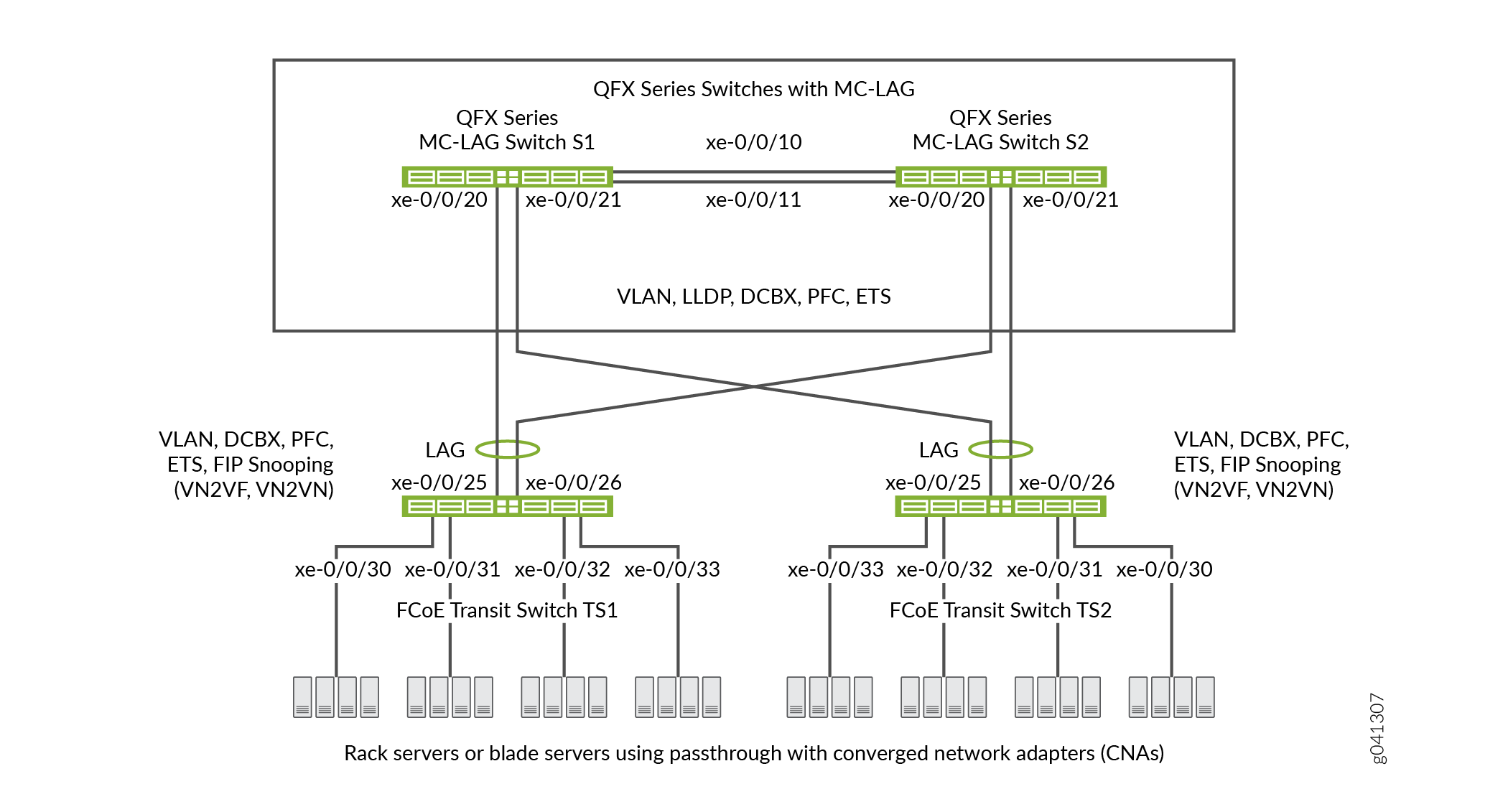
표 3 은 이 예의 구성 요소를 보여줍니다.
구성 요소 |
설정 |
|---|---|
하드웨어 |
스위치 4개(MC-LAG를 패스스루 전송 스위치로 형성하기 위해 2개, FCoE 액세스를 위한 전송 스위치 2개). |
포워딩 클래스(모든 스위치) |
기본 포워딩 클래스입니다 |
분류자(수신 트래픽의 클래스 매핑을 IEEE 우선순위로 전달) |
모든 FCoE 인터페이스의 기본 IEEE 802.1p 신뢰할 수 있는 분류자. |
LAG 및 MC-LAG |
S1 - 포트 xe-0/0/10 및 x-0/0/11은 스위치 S1을 스위치 S2에 연결하는 LAG ae0의 구성원입니다.포트 xe-0/0/20 및 xe-0/0/21은 MC-LAG ae1의 구성원입니다.모든 포트는 포트 모드로 S2 - 포트 xe-0/0/10 및 x-0/0/11은 스위치 S2를 스위치 S1에 연결하는 LAG ae0의 구성원입니다.포트 xe-0/0/20 및 xe-0/0/21은 MC-LAG ae1의 구성원입니다.모든 포트는 포트 모드로
참고:
스위치 S1과 S2의 xe-0/0/20 및 xe-0/0/21 포트는 MC-LAG의 구성원입니다. TS1 - 포트 xe-0/0/25 및 x-0/0/26은 LAG ae1의 구성원으로, 포트 모드에서 구성 TS2 - 포트 xe-0/0/25 및 x-0/0/26은 LAG ae1의 구성원으로, 포트 모드에서 구성 |
FCoE 대기열 스케줄러(모든 스위치) |
|
클래스-스케줄러 매핑 포워딩(모든 스위치) |
스케줄러 맵 |
포워딩 클래스 세트(FCoE 우선 순위 그룹, 모든 스위치) |
송신 인터페이스:
|
트래픽 제어 프로필(모든 스위치) |
|
PFC 혼잡 알림 프로파일(모든 스위치) |
수신 인터페이스:
|
FCoE VLAN 이름 및 태그 ID |
이름— 4개의 스위치 모두에서 FCoE 트래픽을 전달하는 인터페이스에 FCoE VLAN을 포함합니다. 스위치 4개 모두에서 FCoE VLAN에 속하는 인터페이스에서 IGMP 스누핑을 비활성화합니다. |
FIP 스누핑 |
FCoE VLAN의 전송 스위치 TS1 및 TS2에서 FIP 스누핑을 활성화합니다. MC-LAG 스위치에 연결하는 LAG 인터페이스를 FCoE 신뢰할 수 있는 인터페이스로 구성하여 FIP 스누핑을 수행하지 않도록 합니다. 이 예는 FCoE 서버에 연결된 FCoE 전송 스위치 인터페이스에서 VN2VN_Port FIP 스누핑을 활성화합니다. 이 예는 전송 스위치 액세스 포트에서 FIP 스누핑VN2VF_Port 활성화된 경우에도 동일하게 유효합니다. 활성화하는 FIP 스누핑 방법은 네트워크 구성에 따라 다릅니다. |
이 예에서는 명시적으로 구성된 분류자를 적용하지 않을 경우 트렁크 모드 및 태그가 지정된 액세스 모드 포트에 자동으로 적용되는 기본 IEEE 802.1p 신뢰할 수 있는 BA 분류자를 사용합니다.
MC-LAG에서 FCoE 트래픽에 대한 CoS를 구성하려면:
기본 FCoE 포워딩 클래스 및 포워딩 클래스-대기열 매핑을 사용합니다(FCoE 포워딩 클래스 또는 출력 대기열은 명시적으로 구성하지 마십시오). 기본 FCoE 포워딩 클래스는
fcoe이며, 기본 출력 대기열은 대기열3입니다.참고:명시적 포워딩 클래스 구성에 무 손실 패킷 드롭 속성을 포함하여 무손실 포워딩 클래스를 구성할 수 있습니다.
패킷의 IEEE 802.1p 코드 포인트(CoS 우선순위)를 통해 수신 패킷을 포워딩 클래스에 매핑하는 신뢰할 수 있는 기본 BA 분류자를 사용합니다. 신뢰할 수 있는 분류자는 트렁크 및 태그 지정된 액세스 포트 모드의 인터페이스에 대한 기본 분류자입니다. 신뢰할 수 있는 기본 분류자는 IEEE 802.1p 코드 포인트 3(
011)을 사용하여 수신 패킷을 FCoE 포워딩 클래스로 매핑합니다. 기본 분류자를 사용하는 대신 BA 분류자를 구성하기로 선택한 경우, FCoE 트래픽이 두 MC-LAG 스위치 모두에서 정확히 동일한 방식으로 포워딩 클래스로 분류되도록 해야 합니다. 기본 분류자를 사용하면 MC-LAG 포트에서 일관된 분류자 구성이 보장됩니다.FCoE 코드 포인트(이 예의 코드 포인트
011)에서 PFC를 활성화하는 혼잡 알림 프로필을 구성합니다. 혼잡 알림 프로필 구성은 두 MC-LAG 스위치에서 동일해야 합니다.인터페이스에 혼잡 알림 프로필을 적용합니다.
인터페이스에 향상된 전송 선택(ETS, 계층적 스케줄링이라고도 함)을 구성하여 무손실 FCoE 전송에 필요한 대역폭을 제공합니다. ETS 구성에는 FCoE 포워딩 클래스, FCoE 포워딩 클래스를 포함하는 포워딩 클래스 세트(우선 순위 그룹) 및 FCoE 트래픽을 포함하는 포워딩 클래스 세트에 대역폭을 할당하기 위한 트래픽 제어 프로필에 대한 대역폭 스케줄링 구성이 포함됩니다.
인터페이스에 ETS 스케줄링을 적용합니다.
각 인터페이스에 대한 포트 모드, 최대 전송 단위(MTU) 및 FCoE를 신뢰하거나 신뢰할 수 없는 상태를 구성하여 무손실 FCoE 전송을 지원합니다.
또한 이 예에서는 FCoE 서버에 연결된 전송 스위치 TS1 및 TS2 포트에서 FIP 스누핑을 활성화하는 방법과 FCoE VLAN에서 IGMP 스누핑을 비활성화하는 방법을 설명합니다. 안전한 액세스를 제공하려면 FCoE 액세스 포트에서 FIP 스누핑을 활성화해야 합니다.
이 예에서는 MC-LAG에서 무손실 FCoE 전송을 지원하기 위한 CoS 구성에 중점을 둡니다. 이 예에서는 MC-LAG 및 LAG의 속성을 구성하는 방법은 설명하지 않지만, 무손실 전송을 지원하는 데 필요한 포트 특성을 구성하는 방법과 MC-LAG 및 LAG에 인터페이스를 할당하는 방법을 보여줍니다.
CoS를 구성하기 전에 다음을 구성합니다.
스위치 S1 및 S2를 스위치 TS1 및 TS2에 연결하는 MC-LAG입니다.
전송 스위치 TS1 및 TS2를 MC-LAG 스위치 S1 및 S2에 연결하는 LAG입니다.
스위치 S1을 스위치 S2로 연결하는 LAG입니다.
구성
MC-LAG에서 무손실 FCoE 전송을 위해 CoS를 구성하려면 다음 작업을 수행합니다.
CLI 빠른 구성
MC-LAG에서 무손실 FCoE 전송을 위한 CoS를 신속하게 구성하려면 다음 명령을 복사하여 텍스트 파일에 붙여넣고, 줄 바꿈을 제거하고, 네트워크 구성과 일치하도록 변수와 세부 정보를 변경한 다음, 계층 수준에서 [edit] MC-LAG 스위치 S1 및 MC-LAG 스위치 S2의 CLI에 명령을 복사하여 붙여넣습니다. 스위치 S1과 S2의 구성은 CoS 구성이 동일해야 하고 이 예에서는 두 스위치 모두에서 동일한 포트를 사용하기 때문에 동일합니다.
스위치 S1 및 스위치 S2
set class-of-service schedulers fcoe-sched priority low transmit-rate 3g set class-of-service schedulers fcoe-sched shaping-rate percent 100 set class-of-service scheduler-maps fcoe-map forwarding-class fcoe scheduler fcoe-sched set class-of-service forwarding-class-sets fcoe-pg class fcoe set class-of-service traffic-control-profiles fcoe-tcp scheduler-map fcoe-map guaranteed-rate 3g set class-of-service traffic-control-profiles fcoe-tcp shaping-rate percent 100 set class-of-service interfaces ae0 forwarding-class-set fcoe-pg output-traffic-control-profile fcoe-tcp set class-of-service interfaces ae1 forwarding-class-set fcoe-pg output-traffic-control-profile fcoe-tcp set class-of-service congestion-notification-profile fcoe-cnp input ieee-802.1 code-point 011 pfc set class-of-service interfaces ae0 congestion-notification-profile fcoe-cnp set class-of-service interfaces ae1 congestion-notification-profile fcoe-cnp set vlans fcoe_vlan vlan-id 100 set protocols igmp-snooping vlan fcoe_vlan disable set interfaces xe-0/0/10 ether-options 802.3ad ae0 set interfaces xe-0/0/11 ether-options 802.3ad ae0 set interfaces xe-0/0/20 ether-options 802.3ad ae1 set interfaces xe-0/0/21 ether-options 802.3ad ae1 set interfaces ae0 unit 0 family ethernet-switching port-mode trunk vlan members fcoe_vlan set interfaces ae1 unit 0 family ethernet-switching port-mode trunk vlan members fcoe_vlan set interfaces ae0 mtu 2180 set interfaces ae1 mtu 2180 set ethernet-switching-options secure-access-port interface ae0 fcoe-trusted set ethernet-switching-options secure-access-port interface ae1 fcoe-trusted
MC-LAG에서 무손실 FCoE 전송을 위한 CoS를 신속하게 구성하려면 다음 명령을 복사하여 텍스트 파일에 붙여넣고, 줄 바꿈을 제거하고, 네트워크 구성과 일치하도록 변수와 세부 정보를 변경한 다음, 계층 수준에서 [edit] 전송 스위치 TS1 및 전송 스위치 TS2에 대한 CLI에 명령을 복사하여 붙여넣습니다. 스위치 TS1과 TS2의 구성은 CoS 구성이 동일해야 하기 때문에 동일하며, 이 예에서는 두 스위치 모두에서 동일한 포트를 사용하기 때문입니다.
스위치 TS1 및 스위치 TS2
set class-of-service schedulers fcoe-sched priority low transmit-rate 3g set class-of-service schedulers fcoe-sched shaping-rate percent 100 set class-of-service scheduler-maps fcoe-map forwarding-class fcoe scheduler fcoe-sched set class-of-service forwarding-class-sets fcoe-pg class fcoe set class-of-service traffic-control-profiles fcoe-tcp scheduler-map fcoe-map guaranteed-rate 3g set class-of-service traffic-control-profiles fcoe-tcp shaping-rate percent 100 set class-of-service interfaces ae1 forwarding-class-set fcoe-pg output-traffic-control-profile fcoe-tcp set class-of-service interfaces xe-0/0/30 forwarding-class-set fcoe-pg output-traffic-control-profile fcoe-tcp set class-of-service interfaces xe-0/0/31 forwarding-class-set fcoe-pg output-traffic-control-profile fcoe-tcp set class-of-service interfaces xe-0/0/32 forwarding-class-set fcoe-pg output-traffic-control-profile fcoe-tcp set class-of-service interfaces xe-0/0/33 forwarding-class-set fcoe-pg output-traffic-control-profile fcoe-tcp set class-of-service congestion-notification-profile fcoe-cnp input ieee-802.1 code-point 011 pfc set class-of-service interfaces ae1 congestion-notification-profile fcoe-cnp set class-of-service interfaces xe-0/0/30 congestion-notification-profile fcoe-cnp set class-of-service interfaces xe-0/0/31 congestion-notification-profile fcoe-cnp set class-of-service interfaces xe-0/0/32 congestion-notification-profile fcoe-cnp set class-of-service interfaces xe-0/0/33 congestion-notification-profile fcoe-cnp set vlans fcoe_vlan vlan-id 100 set protocols igmp-snooping vlan fcoe_vlan disable set interfaces xe-0/0/25 ether-options 802.3ad ae1 set interfaces xe-0/0/26 ether-options 802.3ad ae1 set interfaces ae1 unit 0 family ethernet-switching port-mode trunk vlan members fcoe_vlan set interfaces xe-0/0/30 unit 0 family ethernet-switching port-mode tagged-access vlan members fcoe_vlan set interfaces xe-0/0/31 unit 0 family ethernet-switching port-mode tagged-access vlan members fcoe_vlan set interfaces xe-0/0/32 unit 0 family ethernet-switching port-mode tagged-access vlan members fcoe_vlan set interfaces xe-0/0/33 unit 0 family ethernet-switching port-mode tagged-access vlan members fcoe_vlan set interfaces ae1 mtu 2180 set interfaces xe-0/0/30 mtu 2180 set interfaces xe-0/0/31 mtu 2180 set interfaces xe-0/0/32 mtu 2180 set interfaces xe-0/0/33 mtu 2180 set ethernet-switching-options secure-access-port interface ae1 fcoe-trusted set ethernet-switching-options secure-access-port vlan fcoe_vlan examine-fip examine-vn2v2 beacon-period 90000
MC-LAG 스위치 S1 및 S2 구성
단계별 절차
MC-LAG에서 무손실 FCoE 전송을 지원하기 위해 CoS ETS(Resource Scheduling), PFC, FCoE VLAN, LAG 및 MC-LAG 인터페이스 멤버십 및 특성을 구성하려면(이 예에서는 기본 fcoe 포워딩 클래스와 기본 분류기를 사용하여 들어오는 FCoE 트래픽을 FCoE IEEE 802.1p 코드 포인트 011에 매핑하므로 구성하지 않음):
FCoE 대기열에 대한 출력 스케줄링을 구성합니다.
[edit class-of-service schedulers fcoe-sched] user@switch# set priority low transmit-rate 3g user@switch# set shaping-rate percent 100
FCoE 포워딩 클래스를 FCoE 스케줄러(
fcoe-sched)에 매핑합니다.[edit class-of-service] user@switch# set scheduler-maps fcoe-map forwarding-class fcoe scheduler fcoe-sched
FCoE 트래픽에 대한 포워딩 클래스 세트(
fcoe-pg)를 구성합니다.[edit class-of-service] user@switch# set forwarding-class-sets fcoe-pg class fcoe
FCoE 포워딩 클래스 집합에서 사용할 트래픽 제어 프로필(
fcoe-tcp)을 정의합니다.[edit class-of-service traffic-control-profiles fcoe-tcp] user@switch# set scheduler-map fcoe-map guaranteed-rate 3g user@switch# set shaping-rate percent 100
FCoE 포워딩 클래스 세트 및 트래픽 제어 프로필을 LAG 및 MC-LAG 인터페이스에 적용합니다.
[edit class-of-service] user@switch# set interfaces ae0 forwarding-class-set fcoe-pg output-traffic-control-profile fcoe-tcp user@switch# set interfaces ae1 forwarding-class-set fcoe-pg output-traffic-control-profile fcoe-tcp
FCoE를 IEEE 802.1 코드 포인트
011에 적용하는 혼잡 알림 프로필(fcoe-cnp)을 생성하여 FCoE 우선순위에서 PFC를 활성화합니다.[edit class-of-service] user@switch# set congestion-notification-profile fcoe-cnp input ieee-802.1 code-point 011 pfc
PFC 구성을 LAG 및 MC-LAG 인터페이스에 적용합니다.
[edit class-of-service] user@switch# set interfaces ae0 congestion-notification-profile fcoe-cnp user@switch# set interfaces ae1 congestion-notification-profile fcoe-cnp
FCoE 트래픽
fcoe_vlan()을 위한 VLAN을 구성합니다.[edit vlans] user@switch# set fcoe_vlan vlan-id 100
FCoE VLAN에서 IGMP 스누핑을 비활성화합니다.
[edit protocols] user@switch# set igmp-snooping vlan fcoe_vlan disable
두 개의 MC-LAG 스위치 사이의 LAG에 멤버 인터페이스를 추가합니다.
[edit interfaces] user@switch# set xe-0/0/10 ether-options 802.3ad ae0 user@switch# set xe-0/0/11 ether-options 802.3ad ae0
MC-LAG에 멤버 인터페이스를 추가합니다.
[edit interfaces] user@switch# set xe-0/0/20 ether-options 802.3ad ae1 user@switch# set xe-0/0/21 ether-options 802.3ad ae1
LAG(ae0) 및 MC-LAG(ae1)에 대한 FCoE VLAN(
fcoe_vlan)의 포트 모드를 구성trunk하고 멤버십을 구성합니다.[edit interfaces] user@switch# set ae0 unit 0 family ethernet-switching port-mode trunk vlan members fcoe_vlan user@switch# set ae1 unit 0 family ethernet-switching port-mode trunk vlan members fcoe_vlan
LAG 및 MC-LAG 인터페이스에 대해 MTU를 로
2180설정합니다.2180바이트는 페이로드 및 헤더 크기 때문에 FCoE 패킷을 처리하는 데 필요한 최소 크기입니다. 원하는 경우 최대 전송 단위(MTU)를 더 높은 바이트 수로 구성할 수 있지만 2180바이트 이상이어야 합니다.
[edit interfaces] user@switch# set ae0 mtu 2180 user@switch# set ae1 mtu 2180
LAG 및 MC-LAG 인터페이스를 FCoE 신뢰할 수 있는 포트로 설정합니다.
다른 스위치에 연결하는 포트는 신뢰해야 하며 FIP 스누핑을 수행해서는 안 됩니다.
[edit ethernet-switching-options secure-access-port interface] user@switch# set ae0 fcoe-trusted user@switch# set ae1 fcoe-trusted
FCoE 전송 스위치 TS1 및 TS2 구성
단계별 절차
FCoE 전송 스위치 TS1 및 TS2의 CoS 구성은 MC-LAG 스위치 S1 및 S2의 CoS 구성과 유사합니다. 그러나 포트 구성이 다르므로 스위치 TS1 및 스위치 TS2 FCoE 액세스 포트에서 FIP 스누핑을 활성화해야 합니다.
MC-LAG에서 무손실 FCoE 전송을 지원하기 위해 ETS(Resource Scheduling), PFC, FCoE VLAN 및 LAG 인터페이스 구성원 및 특성을 구성하기 위해(이 예에서는 기본 fcoe 포워딩 클래스와 기본 분류자를 사용하여 들어오는 FCoE 트래픽을 FCoE IEEE 802.1p 코드 포인트 011에 매핑하므로 구성하지 않음):
FCoE 대기열에 대한 출력 스케줄링을 구성합니다.
[edit class-of-service schedulers fcoe-sched] user@switch# set priority low transmit-rate 3g user@switch# set shaping-rate percent 100
FCoE 포워딩 클래스를 FCoE 스케줄러(
fcoe-sched)에 매핑합니다.[edit class-of-service] user@switch# set scheduler-maps fcoe-map forwarding-class fcoe scheduler fcoe-sched
FCoE 트래픽에 대한 포워딩 클래스 세트(
fcoe-pg)를 구성합니다.[edit class-of-service] user@switch# set forwarding-class-sets fcoe-pg class fcoe
FCoE 포워딩 클래스 집합에서 사용할 트래픽 제어 프로필(
fcoe-tcp)을 정의합니다.[edit class-of-service] user@switch# set traffic-control-profiles fcoe-tcp scheduler-map fcoe-map guaranteed-rate 3g user@switch# set traffic-control-profiles fcoe-tcp shaping-rate percent 100
FCoE 포워딩 클래스 세트 및 트래픽 제어 프로필을 LAG 인터페이스 및 FCoE 액세스 인터페이스에 적용합니다.
[edit class-of-service] user@switch# set interfaces ae1 forwarding-class-set fcoe-pg output-traffic-control-profile fcoe-tcp user@switch# set interfaces xe-0/0/30 forwarding-class-set fcoe-pg output-traffic-control-profile fcoe-tcp user@switch# set interfaces xe-0/0/31 forwarding-class-set fcoe-pg output-traffic-control-profile fcoe-tcp user@switch# set interfaces xe-0/0/32 forwarding-class-set fcoe-pg output-traffic-control-profile fcoe-tcp user@switch# set interfaces xe-0/0/33 forwarding-class-set fcoe-pg output-traffic-control-profile fcoe-tcp
FCoE를 IEEE 802.1 코드 포인트
011에 적용하는 혼잡 알림 프로필(fcoe-cnp)을 생성하여 FCoE 우선순위에서 PFC를 활성화합니다.[edit class-of-service] user@switch# set congestion-notification-profile fcoe-cnp input ieee-802.1 code-point 011 pfc
PFC 구성을 LAG 인터페이스 및 FCoE 액세스 인터페이스에 적용합니다.
[edit class-of-service] user@switch# set interfaces ae1 congestion-notification-profile fcoe-cnp user@switch# set interfaces xe-0/0/30 congestion-notification-profile fcoe-cnp user@switch# set interfaces xe-0/0/31 congestion-notification-profile fcoe-cnp user@switch# set interfaces xe-0/0/32 congestion-notification-profile fcoe-cnp user@switch# set interfaces xe-0/0/33 congestion-notification-profile fcoe-cnp
FCoE 트래픽
fcoe_vlan()을 위한 VLAN을 구성합니다.[edit vlans] user@switch# set fcoe_vlan vlan-id 100
FCoE VLAN에서 IGMP 스누핑을 비활성화합니다.
[edit protocols] user@switch# set igmp-snooping vlan fcoe_vlan disable
LAG에 멤버 인터페이스를 추가합니다.
[edit interfaces] user@switch# set xe-0/0/25 ether-options 802.3ad ae1 user@switch# set xe-0/0/26 ether-options 802.3ad ae1
LAG(
ae1)에서 포트 모드를 구성하고 FCoE VLAN(fcoe_vlan)의 멤버십을 구성trunk합니다.[edit interfaces] user@switch# set ae1 unit 0 family ethernet-switching port-mode trunk vlan members fcoe_vlan
FCoE 액세스 인터페이스(, , , )
xe-0/0/33에서 포트 모드를 구성하고 FCoE VLANfcoe_vlan()의 멤버십을 구성합니다tagged-access.xe-0/0/32xe-0/0/31xe-0/0/30[edit interfaces] user@switch# set xe-0/0/30 unit 0 family ethernet-switching port-mode tagged-access vlan members fcoe_vlan user@switch# set xe-0/0/31 unit 0 family ethernet-switching port-mode tagged-access vlan members fcoe_vlan user@switch# set xe-0/0/32 unit 0 family ethernet-switching port-mode tagged-access vlan members fcoe_vlan user@switch# set xe-0/0/33 unit 0 family ethernet-switching port-mode tagged-access vlan members fcoe_vlan
LAG 및 FCoE 액세스 인터페이스에 대해 MTU를 로
2180설정합니다.2180바이트는 페이로드 및 헤더 크기 때문에 FCoE 패킷을 처리하는 데 필요한 최소 크기입니다. 원하는 경우 최대 전송 단위(MTU)를 더 많은 바이트로 구성할 수 있지만 2180바이트 이상이어야 합니다.
[edit interfaces] user@switch# set ae1 mtu 2180 user@switch# set xe-0/0/30 mtu 2180 user@switch# set xe-0/0/31 mtu 2180 user@switch# set xe-0/0/32 mtu 2180 user@switch# set xe-0/0/33 mtu 2180
LAG 인터페이스를 FCoE 신뢰할 수 있는 포트로 설정합니다. 다른 스위치에 연결하는 포트는 신뢰해야 하며 FIP 스누핑을 수행해서는 안 됩니다.
[edit ethernet-switching-options] user@switch# set secure-access-port interface ae1 fcoe-trusted
참고:액세스 포트 xe-0/0/30, xe-0/0/31, xe-0/0/32, xe-0/0/33은 FCoE 신뢰할 수 있는 포트로 구성되지 않습니다. 액세스 포트는 FCoE 디바이스에 직접 연결되고 네트워크 보안을 보장하기 위해 FIP 스누핑을 수행해야 하기 때문에 신뢰할 수 없는 포트로 기본 상태로 유지됩니다.
FCoE VLAN에서 FIP 스누핑을 활성화하여 무단 FCoE 네트워크 액세스를 방지합니다(이 예에서는 VN2VN_Port FIP 스누핑을 사용합니다. 이 예는 VN2VF_Port FIP 스누핑을 사용하는 경우에도 동일하게 유효함).
[edit ethernet-switching-options] user@switch# set secure-access-port vlan fcoe_vlan examine-fip examine-vn2vn beacon-period 90000
결과
MC-LAG 스위치 S1과 MC-LAG 스위치 S2에 CoS 구성 결과를 표시합니다(두 스위치의 결과는 동일함).
user@switch> show configuration class-of-service
traffic-control-profiles {
fcoe-tcp {
scheduler-map fcoe-map;
shaping-rate percent 100;
guaranteed-rate 3g;
}
}
forwarding-class-sets {
fcoe-pg {
class fcoe;
}
}
congestion-notification-profile {
fcoe-cnp {
input {
ieee-802.1 {
code-point 011 {
pfc;
}
}
}
}
}
interfaces {
ae0 {
forwarding-class-set {
fcoe-pg {
output-traffic-control-profile fcoe-tcp;
}
}
congestion-notification-profile fcoe-cnp;
}
ae1 {
forwarding-class-set {
fcoe-pg {
output-traffic-control-profile fcoe-tcp;
}
}
congestion-notification-profile fcoe-cnp;
}
}
scheduler-maps {
fcoe-map {
forwarding-class fcoe scheduler fcoe-sched;
}
}
schedulers {
fcoe-sched {
transmit-rate 3g;
shaping-rate percent 100;
priority low;
}
}
명령이 구성의 기본 부분을 표시하지 않기 때문에 show 포워딩 클래스 및 분류자 구성이 표시되지 않습니다.
FCoE 전송 스위치 TS1과 FCoE 전송 스위치 TS2에 CoS 구성 결과를 표시합니다(두 전송 스위치의 결과는 동일함).
user@switch> show configuration class-of-service
traffic-control-profiles {
fcoe-tcp {
scheduler-map fcoe-map;
shaping-rate percent 100;
guaranteed-rate 3g;
}
}
forwarding-class-sets {
fcoe-pg {
class fcoe;
}
}
congestion-notification-profile {
fcoe-cnp {
input {
ieee-802.1 {
code-point 011 {
pfc;
}
}
}
}
}
interfaces {
xe-0/0/30 {
forwarding-class-set {
fcoe-pg {
output-traffic-control-profile fcoe-tcp;
}
}
congestion-notification-profile fcoe-cnp;
}
xe-0/0/31 {
forwarding-class-set {
fcoe-pg {
output-traffic-control-profile fcoe-tcp;
}
}
congestion-notification-profile fcoe-cnp;
}
xe-0/0/32 {
forwarding-class-set {
fcoe-pg {
output-traffic-control-profile fcoe-tcp;
}
}
congestion-notification-profile fcoe-cnp;
}
xe-0/0/33 {
forwarding-class-set {
fcoe-pg {
output-traffic-control-profile fcoe-tcp;
}
}
congestion-notification-profile fcoe-cnp;
}
ae1 {
forwarding-class-set {
fcoe-pg {
output-traffic-control-profile fcoe-tcp;
}
}
congestion-notification-profile fcoe-cnp;
}
}
scheduler-maps {
fcoe-map {
forwarding-class fcoe scheduler fcoe-sched;
}
}
schedulers {
fcoe-sched {
transmit-rate 3g;
shaping-rate percent 100;
priority low;
}
}
검증
CoS 구성 요소 및 FIP 스누핑이 구성되고 제대로 작동하는지 확인하려면 다음 작업을 수행합니다. 이 예에서는 기본 fcoe 포워딩 클래스와 기본 IEEE 802.1p 신뢰할 수 있는 분류자를 사용하기 때문에 이러한 구성의 확인은 표시되지 않습니다.
- 출력 대기열 스케줄러가 생성되었는지 확인
- 우선순위 그룹 출력 스케줄러(트래픽 제어 프로필)가 생성되었는지 확인
- 포워딩 클래스 세트(우선 순위 그룹)가 생성되었는지 확인
- 우선순위 기반 플로우 제어가 활성화되었는지 확인
- 인터페이스 서비스 등급 구성이 생성되었는지 확인
- 인터페이스가 올바르게 구성되었는지 확인
- FCoE 전송 스위치의 FCoE VLAN에서 FIP 스누핑이 활성화되었는지 확인 TS1 및 TS2 액세스 인터페이스
- FCoE 전송 스위치 TS1 및 TS2에서 FIP 스누핑 모드가 올바른지 확인
- FCoE VLAN에서 IGMP 스누핑이 비활성화되었는지 확인
출력 대기열 스케줄러가 생성되었는지 확인
목적
FCoE 트래픽에 대한 출력 대기열 스케줄러가 올바른 대역폭 매개 변수와 우선 순위를 가지고, 올바른 포워딩 클래스(출력 대기열)에 매핑되었는지 확인합니다. 대기열 스케줄러 확인은 4개의 스위치 각각에서 동일합니다.
작업
운영 모드 명령을 show class-of-service scheduler-map fcoe-map사용하여 스케줄러 맵을 나열합니다.
user@switch> show class-of-service scheduler-map fcoe-map
Scheduler map: fcoe-map, Index: 9023
Scheduler: fcoe-sched, Forwarding class: fcoe, Index: 37289
Transmit rate: 3000000000 bps, Rate Limit: none, Buffer size: remainder,
Buffer Limit: none, Priority: low
Excess Priority: unspecified
Shaping rate: 100 percent,
drop-profile-map-set-type: mark
Drop profiles:
Loss priority Protocol Index Name
Low any 1 <default-drop-profile>
Medium high any 1 <default-drop-profile>
High any 1 <default-drop-profile>
의미
이 명령은 show class-of-service scheduler-map fcoe-map 스케줄러 맵 fcoe-map의 속성을 나열합니다. 명령 출력에는 다음이 포함됩니다.
스케줄러 맵(
fcoe-map)의 이름입니다스케줄러의 이름(
fcoe-sched)스케줄러(
fcoe)에 매핑된 포워딩 클래스최소 보장 대기열 대역폭(전송 속도
3000000000 bps)스케줄링 우선순위(
low)대기열이 사용할 수 있는 우선 순위 그룹의 최대 대역폭(셰이핑 속도
100 percent)각 드롭 프로파일 이름에 대한 드롭 프로파일 손실 우선순위입니다. 이 예에서는 FCoE 트래픽에 드롭 프로필을 적용하지 않으므로 드롭 프로필을 포함하지 않습니다.
우선순위 그룹 출력 스케줄러(트래픽 제어 프로필)가 생성되었는지 확인
목적
트래픽 제어 프로필 fcoe-tcp 이 올바른 대역폭 매개 변수 및 스케줄러 매핑으로 생성되었는지 확인합니다. 우선순위 그룹 스케줄러 확인은 4개의 스위치 각각에서 동일합니다.
작업
운영 모드 명령을 show class-of-service traffic-control-profile fcoe-tcp사용하여 FCoE 트래픽 제어 프로필 속성을 나열합니다.
user@switch> show class-of-service traffic-control-profile fcoe-tcp Traffic control profile: fcoe-tcp, Index: 18303 Shaping rate: 100 percent Scheduler map: fcoe-map Guaranteed rate: 3000000000
의미
이 명령은 show class-of-service traffic-control-profile fcoe-tcp 구성된 모든 트래픽 제어 프로필을 나열합니다. 각 트래픽 제어 프로필의 경우, 명령 출력에는 다음이 포함됩니다.
트래픽 제어 프로필()의 이름입니다.
fcoe-tcp우선 순위 그룹이 사용할 수 있는 최대 포트 대역폭(셰이핑 속도
100 percent)트래픽 제어 프로필(
fcoe-map)과 연결된 스케줄러 맵최소 보장 우선순위 그룹 포트 대역폭(bps 단위의 보장 속도
3000000000)
포워딩 클래스 세트(우선 순위 그룹)가 생성되었는지 확인
목적
FCoE 우선 순위 그룹이 생성되었고 우선 순위(포워딩 클래스)가 fcoe FCoE 우선 순위 그룹에 속하는지 확인합니다. 포워딩 클래스 집합 확인은 4개의 스위치 각각에서 동일합니다.
작업
운영 모드 명령을 show class-of-service forwarding-class-set fcoe-pg사용하여 포워딩 클래스 세트를 나열합니다.
user@switch> show class-of-service forwarding-class-set fcoe-pg Forwarding class set: fcoe-pg, Type: normal-type, Forwarding class set index: 31420 Forwarding class Index fcoe 1
의미
이 명령은 show class-of-service forwarding-class-set fcoe-pg 우선 순위 그룹에 속 fcoe-pg 하는 모든 포워딩 클래스(우선 순위)와 우선 순위 그룹의 내부 인덱스 번호를 나열합니다. 명령 출력은 포워딩 클래스 세트 fcoe-pg 에 포워딩 클래스 fcoe가 포함되어 있음을 보여줍니다.
우선순위 기반 플로우 제어가 활성화되었는지 확인
목적
FCoE 코드 포인트에서 PFC가 활성화되었는지 확인합니다. PFC 검증은 4개의 스위치 각각에서 동일합니다.
작업
운영 모드 명령을 show class-of-service congestion-notification fcoe-cnp사용하여 FCoE 혼잡 알림 프로필을 나열합니다.
user@switch> show class-of-service congestion-notification fcoe-cnp
Type: Input, Name: fcoe-cnp, Index: 6879
Cable Length: 100 m
Priority PFC MRU
000 Disabled
001 Disabled
010 Disabled
011 Enabled 2500
100 Disabled
101 Disabled
110 Disabled
111 Disabled
Type: Output
Priority Flow-Control-Queues
000
0
001
1
010
2
011
3
100
4
101
5
110
6
111
7
의미
이 명령은 show class-of-service congestion-notification fcoe-cnp PFC가 활성화된 혼잡 알림 프로필의 모든 IEEE 802.1p 코드 포인트를 나열합니다. 명령 출력은 PFC가 혼잡 알림 프로필의 fcoe-cnp 코드 포인트 011 (fcoe대기열)에서 활성화되어 있음을 보여줍니다.
이 명령은 또한 기본 케이블 길이(100 미터), 기본 최대 수신 단위(2500 바이트) 및 출력 대기열에 대한 우선 순위의 기본 매핑을 보여줍니다. 이 예에서는 이러한 옵션 구성을 포함하지 않습니다.
인터페이스 서비스 등급 구성이 생성되었는지 확인
목적
인터페이스의 CoS 속성이 올바른지 확인합니다. MC-LAG 스위치 S1 및 S2의 검증 출력은 FCoE 전송 스위치 TS1 및 TS2의 출력과 다릅니다.
작업
운영 모드 명령을 show configuration class-of-service interfaces사용하여 MC-LAG 스위치 S1 및 S2에서 인터페이스 CoS 구성을 나열합니다.
user@switch> show configuration class-of-service interfaces
ae0 {
forwarding-class-set {
fcoe-pg {
output-traffic-control-profile fcoe-tcp;
}
}
congestion-notification-profile fcoe-cnp;
}
ae1 {
forwarding-class-set {
fcoe-pg {
output-traffic-control-profile fcoe-tcp;
}
}
congestion-notification-profile fcoe-cnp;
}
운영 모드 명령을 show configuration class-of-service interfaces사용하여 FCoE 전송 스위치 TS1 및 TS2의 인터페이스 CoS 구성을 나열합니다.
user@switch> show configuration class-of-service interfaces
xe-0/0/30 {
forwarding-class-set {
fcoe-pg {
output-traffic-control-profile fcoe-tcp;
}
}
congestion-notification-profile fcoe-cnp;
}
xe-0/0/31 {
forwarding-class-set {
fcoe-pg {
output-traffic-control-profile fcoe-tcp;
}
}
congestion-notification-profile fcoe-cnp;
}
xe-0/0/32 {
forwarding-class-set {
fcoe-pg {
output-traffic-control-profile fcoe-tcp;
}
}
congestion-notification-profile fcoe-cnp;
}
xe-0/0/33 {
forwarding-class-set {
fcoe-pg {
output-traffic-control-profile fcoe-tcp;
}
}
congestion-notification-profile fcoe-cnp;
}
ae1 {
forwarding-class-set {
fcoe-pg {
output-traffic-control-profile fcoe-tcp;
}
}
congestion-notification-profile fcoe-cnp;
}
의미
이 명령은 show configuration class-of-service interfaces 모든 인터페이스에 대한 서비스 등급 구성을 나열합니다. 각 인터페이스의 경우 명령 출력에는 다음이 포함됩니다.
인터페이스의 이름(예:
ae0xe-0/0/30또는 )인터페이스(
fcoe-pg)와 연관된 포워딩 클래스 세트의 이름인터페이스와 연결된 트래픽 제어 프로필의 이름(출력 트래픽 제어 프로필,
fcoe-tcp)인터페이스()와 연결된 혼잡 알림 프로필의 이름입니다
fcoe-cnp
LAG의 구성원인 인터페이스는 개별적으로 표시되지 않습니다. LAG 또는 MC-LAG CoS 구성은 LAG 또는 MC-LAG의 구성원인 모든 인터페이스에 적용됩니다. 예를 들어, MC-LAG 스위치 S1과 S2의 인터페이스 CoS 구성 출력은 LAG CoS 구성을 보여주지만 멤버 인터페이스의 CoS 구성을 별도로 보여주지는 않습니다. FCoE 전송 스위치 TS1 및 TS2의 인터페이스 CoS 구성 출력은 LAG CoS 구성을 보여주지만 LAG의 구성원이 아닌 인터페이스 xe-0/0/30, xe-0/0/31, xe-0/0/32, xe-0/0/33의 구성도 보여줍니다.
인터페이스가 올바르게 구성되었는지 확인
목적
인터페이스의 LAG 멤버십, MTU, VLAN 멤버십 및 포트 모드가 올바른지 확인합니다. MC-LAG 스위치 S1 및 S2의 검증 출력은 FCoE 전송 스위치 TS1 및 TS2의 출력과 다릅니다.
작업
운영 모드 명령을 show configuration interfaces사용하여 MC-LAG 스위치 S1 및 S2의 인터페이스 구성을 나열합니다.
user@switch> show configuration interfaces
xe-0/0/10 {
ether-options {
802.3ad ae0;
}
}
xe-0/0/11 {
ether-options {
802.3ad ae0;
}
}
xe-0/0/20 {
ether-options {
802.3ad ae1;
}
}
xe-0/0/21 {
ether-options {
802.3ad ae1;
}
}
ae0 {
mtu 2180;
unit 0 {
family ethernet-switching {
port-mode trunk;
vlan {
members fcoe_vlan;
}
}
}
}
ae1 {
mtu 2180;
unit 0 {
family ethernet-switching {
port-mode trunk;
vlan {
members fcoe_vlan;
}
}
}
}
운영 모드 명령을 show configuration interfaces사용하여 FCoE 전송 스위치 TS1 및 TS2의 인터페이스 구성을 나열합니다.
user@switch> show configuration interfaces
xe-0/0/25 {
ether-options {
802.3ad ae1;
}
}
xe-0/0/26 {
ether-options {
802.3ad ae1;
}
}
xe-0/0/30 {
mtu 2180;
unit 0 {
family ethernet-switching {
port-mode tagged-access;
vlan {
members fcoe_vlan;
}
}
}
}
xe-0/0/31 {
mtu 2180;
unit 0 {
family ethernet-switching {
port-mode tagged-access;
vlan {
members fcoe_vlan;
}
}
}
}
xe-0/0/32 {
mtu 2180;
unit 0 {
family ethernet-switching {
port-mode tagged-access;
vlan {
members fcoe_vlan;
}
}
}
}
xe-0/0/33 {
mtu 2180;
unit 0 {
family ethernet-switching {
port-mode tagged-access;
vlan {
members fcoe_vlan;
}
}
}
}
ae1 {
mtu 2180;
unit 0 {
family ethernet-switching {
port-mode trunk;
vlan {
members fcoe_vlan;
}
}
}
}
의미
이 명령은 show configuration interfaces 인터페이스 이름별로 각 인터페이스의 구성을 나열합니다.
LAG의 구성원인 각 인터페이스에 대해 명령은 인터페이스가 속한 LAG의 이름만 나열합니다.
각 LAG 인터페이스 및 LAG의 멤버가 아닌 각 인터페이스에 대해 명령 출력에는 다음이 포함됩니다.
최대 전송 단위(MTU)
2180인터페이스의 단위 번호(
0)입니다포트 모드(
trunk두 스위치를 연결하는 인터페이스용 모드,tagged-accessFCoE 호스트에 연결하는 인터페이스용 모드)인터페이스가 멤버인 VLAN의 이름(
fcoe_vlan)입니다
FCoE 전송 스위치의 FCoE VLAN에서 FIP 스누핑이 활성화되었는지 확인 TS1 및 TS2 액세스 인터페이스
목적
FCoE VLAN 액세스 인터페이스에서 FIP 스누핑이 활성화되었는지 확인합니다. FIP 스누핑은 FCoE 액세스 인터페이스에서만 활성화되므로 FCoE 전송 스위치 TS1 및 TS2에서만 활성화됩니다. FIP 스누핑은 전송 스위치 TS1 및 TS2 FCoE 액세스 포트에서 수행되기 때문에 MC-LAG 스위치 S1 및 S2에서는 FIP 스누핑이 활성화되지 않습니다.
작업
운영 모드 명령을 show configuration ethernet-switching-options secure-access-port사용하여 FCoE 전송 스위치 TS1 및 TS2의 포트 보안 구성을 나열합니다.
user@switch> show configuration ethernet-switching-options secure-access-port
interface ae1.0 {
fcoe-trusted;
}
vlan fcoe_vlan {
examine-fip {
examine-vn2vn {
beacon-period 90000;
}
}
}
의미
이 명령은 show configuration ethernet-switching-options secure-access-port 포트가 신뢰할 수 있는지 여부를 포함하여 포트 보안 정보를 나열합니다. 명령 출력은 다음을 보여줍니다.
FCoE 전송 스위치를 MC-LAG 스위치에 연결하는 LAG 포트
ae1.0는 FCoE 신뢰할 수 있는 인터페이스로 구성됩니다. FIP 스누핑은 LAG의 멤버 인터페이스(xe-0/0/25 및 xe-0/0/26)에서 수행되지 않습니다.FIP 스누핑은 FCoE VLAN(
fcoe_vlan)에서 활성화되고(examine-fip)하고, FIP 스누핑 유형은 FIP 스누핑(examine-vn2vn)VN2VN_Port이며, 비콘 주기는 밀리초로90000설정됩니다. 전송 스위치 TS1 및 TS2에서 인터페이스가 FCoE 신뢰할 수 있는 것으로 구성되지 않는 한 FCoE VLAN의 모든 인터페이스 구성원은 FIP 스누핑을 수행합니다. 전송 스위치 TS1 및 TS2에서 인터페이스 xe-0/0/30, xe-0/0/31, xe-0/0/32 및 xe-0/0/33은 FCoE가 신뢰할 수 있는 것으로 구성되지 않았기 때문에 FIP 스누핑을 수행합니다. LAG ae1(xe-0/0/25 및 xe-0/0/26)의 인터페이스 멤버는 LAG가 FCoE로 구성되어 있으므로 FIP 스누핑을 수행하지 않습니다.
FCoE 전송 스위치 TS1 및 TS2에서 FIP 스누핑 모드가 올바른지 확인
목적
FCoE VLAN에서 FIP 스누핑 모드가 올바른지 확인합니다. FIP 스누핑은 FCoE 액세스 인터페이스에서만 활성화되므로 FCoE 전송 스위치 TS1 및 TS2에서만 활성화됩니다. FIP 스누핑은 전송 스위치 TS1 및 TS2 FCoE 액세스 포트에서 수행되기 때문에 MC-LAG 스위치 S1 및 S2에서는 FIP 스누핑이 활성화되지 않습니다.
작업
운영 모드 명령을 show fip snooping brief사용하여 FCoE 전송 스위치 TS1 및 TS2에서 FIP 스누핑 구성을 나열합니다.
user@switch> show fip snooping brief VLAN: fcoe_vlan, Mode: VN2VN Snooping FC-MAP: 0e:fd:00 …
관련 정보만 표시하도록 출력이 잘렸습니다.
의미
이 명령은 show fip snooping brief FIP 스누핑 VLAN 및 FIP 스누핑 모드를 포함한 FIP 스누핑 정보를 나열합니다. 명령 출력은 다음을 보여줍니다.
FIP 스누핑이 활성화된 VLAN은
fcoe_vlanFIP 스누핑 모드는 FIP 스누핑(
VN2VN Snooping)VN2VN_Port입니다.
FCoE VLAN에서 IGMP 스누핑이 비활성화되었는지 확인
목적
스위치 4개 모두의 FCoE VLAN에서 IGMP 스누핑이 비활성화되어 있는지 확인합니다.
작업
다음 명령을 사용하여 4개의 스위치 각각에 대한 IGMP 스누핑 프로토콜 정보를 나열합니다.show configuration protocols igmp-snooping
user@switch> show configuration protocols igmp-snooping
vlan fcoe_vlan {
disable;
}
의미
이 명령은 show configuration protocols igmp-snooping 스위치에 구성된 VLAN에 대한 IGMP 스누핑 구성을 나열합니다. 명령 출력은 IGMP 스누핑이 FCoE VLAN(fcoe_vlan)에서 비활성화되어 있음을 보여줍니다.
예: MC-LAG 토폴로지와 EVPN-MPLS 연동
이 예시는 이더넷 VPN(EVPN)을 사용하여 MPLS 네트워크를 통해 데이터센터 네트워크 또는 지리적으로 분산된 캠퍼스 네트워크로 MC-LAG(Multichassis Link Aggregation) 네트워크를 확장하는 방법을 보여줍니다.
EVPN-MPLS 상호 연동은 MX 시리즈 라우터 2개, EX9200 스위치 2개 또는 주니퍼 네트웍스 디바이스의 조합이 MC-LAG 피어로 작동하는 MC-LAG 토폴로지로 지원되며, 이 피어는 섀시 간 제어 프로토콜(ICCP) 및 섀시 간 링크(ICL)를 사용하여 토폴로지를 연결하고 유지합니다. MC-LAG 피어는 MPLS 네트워크의 프로바이더 에지(PE) 디바이스에 연결됩니다. PE 디바이스는 MX 시리즈 라우터 또는 EX9200 스위치가 될 수 있습니다.
이 예는 MPLS 네트워크의 MC-LAG 피어 및 PE 디바이스가 서로 상호 작용하도록 구성하는 방법을 보여줍니다.
요구 사항
이 예에서 사용되는 하드웨어 및 소프트웨어 구성 요소는 다음과 같습니다.
EX9200 스위치 3개:
PE1 및 PE2는 모두 MC-LAG 토폴로지에서 MC-LAG 피어 및 EVPN-MPLS 오버레이 네트워크에서 EVPN BGP 피어로 기능합니다.
PE3는 EVPN-MPLS 오버레이 네트워크에서 EVPN BGP 피어로 작동합니다.
EX9200 스위치는 Junos OS 릴리스 17.4R1 이상 소프트웨어를 실행하고 있습니다.
MC-LAG 토폴로지에는 두 개의 고객 에지(CE) 디바이스가 포함되어 있지만, 이 예에서는 PE1, PE2 및 PE3의 구성에 초점을 맞춥니다.
개요 및 토폴로지
그림 7 은 MC-LAG 피어로 구성된 프로바이더 에지 디바이스 PE1 및 PE2가 있는 MC-LAG 토폴로지를 보여줍니다. MC-LAG 피어는 ICCP 링크를 통해 제어 정보와 ICL을 통해 데이터 트래픽을 교환합니다. 이 예에서 ICL은 두 개의 인터페이스로 구성된 어그리게이션 이더넷 인터페이스입니다.
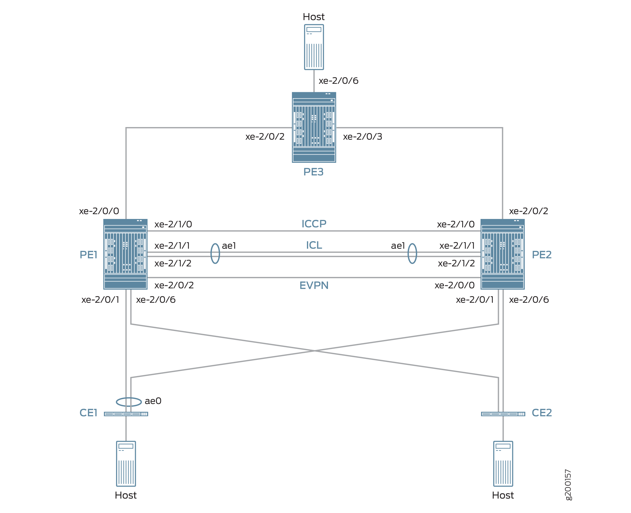
그림 7의 토폴로지에는 각 PE 디바이스에 멀티호밍된 CE 디바이스 CE1과 CE2도 포함됩니다. CE1과 두 PE 디바이스 간의 링크는 액티브-액티브 모드의 MC-LAG가 구성된 어그리게이션 이더넷 인터페이스로 번들로 제공됩니다.
그림 7의 토폴로지에는 MPLS 네트워크 에지의 PE3도 포함됩니다. PE3는 MC-LAG 네트워크와 데이터센터 또는 지리적으로 분산된 캠퍼스 네트워크 간의 게이트웨이 역할을 합니다. PE1, PE2 및 PE3는 EVPN을 실행하며, 이는 MC-LAG 네트워크의 호스트가 개입하는 MPLS 네트워크를 통해 데이터센터 또는 다른 캠퍼스 네트워크의 호스트와 통신할 수 있도록 합니다.
EVPN-MPLS 상호 연동 기능의 관점에서 PE3는 EVPN BGP 피어로서만 작동하며, MC-LAG 토폴로지에서 PE1과 PE2는 이중 역할을 합니다.
MC-LAG 네트워크의 MC-LAG 피어입니다.
EVPN-MPLS 네트워크의 EVPN BGP 피어입니다.
이중 역할 때문에 PE1과 PE2는 MC-LAG, EVPN, BGP 및 MPLS 속성으로 구성됩니다.
표 4 에는 PE1, PE2 및 PE3에 구성된 주요 MC-LAG 및 EVPN(BGP 및 MPLS) 속성이 나와 있습니다.
주요 속성 |
PE1 |
PE2 |
PE3 |
|---|---|---|---|
MC-LAG Attributes |
|||
인터페이스 |
ICL: xe-2/1/1 및 xe-2/1/2로 구성된 어그리게이션 이더넷 인터페이스 ae1 ICCP: xe-2/1/0 |
ICL: xe-2/1/1 및 xe-2/1/2로 구성된 어그리게이션 이더넷 인터페이스 ae1 ICCP: xe-2/1/0 |
해당 사항 없음 |
EVPN-MPLS |
|||
인터페이스 |
PE3에 연결: xe-2/0/0 PE2에 연결: xe-2/0/2 |
PE3에 연결: xe-2/0/2 PE1에 연결: xe-2/0/0 |
PE1에 연결: xe-2/0/2 PE2에 연결: xe-2/0/3 |
IP 주소 |
BGP 피어 주소: 198.51.100.1 |
BGP 피어 주소: 198.51.100.2 |
BGP 피어 주소: 198.51.100.3 |
자율 시스템 |
65000 |
65000 |
65000 |
가상 스위치 라우팅 인스턴스 |
EVPN1, EVPN2, EVPN3 |
EVPN1, EVPN2, EVPN3 |
EVPN1, EVPN2, EVPN3 |
EVPN-MPLS 상호 연동 기능 및 해당 구성에 대해 다음 사항에 유의하십시오.
MC-LAG 토폴로지의 듀얼호밍 인터페이스에서 이더넷 세그먼트 식별자(ESI)를 구성해야 합니다. ESI를 통해 EVPN은 듀얼호밍 인터페이스를 식별할 수 있습니다.
지원되는 유일한 라우팅 인스턴스 유형은 가상 스위치 인스턴스(
set routing-instances name instance-type virtual-switch)입니다.MC-LAG 피어에서는 계층 수준에 구성
[edit routing-instances name protocols evpn mclag]문을 포함bgp-peer해야 합니다. 이 구성 문은 MC-LAG 피어에서 EVPN-MPLS와 MC-LAG의 연동을 가능하게 합니다.ARP(Address Resolution Protocol) 억제는 지원되지 않습니다.
PE1 및 PE2 구성
PE1 및 PE2를 구성하려면 다음 작업을 수행하십시오.
CLI 빠른 구성
PE1: MC-LAG 구성
set chassis aggregated-devices ethernet device-count 3 set interfaces xe-2/0/1 gigether-options 802.3ad ae0 set interfaces ae0 flexible-vlan-tagging set interfaces ae0 encapsulation flexible-ethernet-services set interfaces ae0 aggregated-ether-options lacp active set interfaces ae0 aggregated-ether-options lacp periodic fast set interfaces ae0 aggregated-ether-options lacp system-id 00:00:11:11:11:11 set interfaces ae0 aggregated-ether-options lacp admin-key 1 set interfaces ae0 aggregated-ether-options mc-ae mc-ae-id 1 set interfaces ae0 aggregated-ether-options mc-ae redundancy-group 2 set interfaces ae0 aggregated-ether-options mc-ae chassis-id 0 set interfaces ae0 aggregated-ether-options mc-ae mode active-active set interfaces ae0 aggregated-ether-options mc-ae status-control active set interfaces ae0 unit 1 esi 00:11:22:33:44:55:66:77:88:99 set interfaces ae0 unit 1 esi all-active set interfaces ae0 unit 1 family ethernet-switching interface-mode trunk set interfaces ae0 unit 1 family ethernet-switching vlan members 1 set interfaces ae0 unit 2 esi 00:11:11:11:11:11:11:11:11:11 set interfaces ae0 unit 2 esi all-active set interfaces ae0 unit 2 family ethernet-switching interface-mode trunk set interfaces ae0 unit 2 family ethernet-switching vlan members 2 set interfaces ae0 unit 3 esi 00:11:22:22:22:22:22:22:22:22 set interfaces ae0 unit 3 esi all-active set interfaces ae0 unit 3 family ethernet-switching interface-mode trunk set interfaces ae0 unit 3 family ethernet-switching vlan members 3 set interfaces xe-2/0/6 enable set interfaces xe-2/0/6 flexible-vlan-tagging set interfaces xe-2/0/6 encapsulation flexible-ethernet-services set interfaces xe-2/0/6 unit 1 family ethernet-switching interface-mode trunk set interfaces xe-2/0/6 unit 1 family ethernet-switching vlan members 1 set interfaces xe-2/0/6 unit 2 family ethernet-switching interface-mode trunk set interfaces xe-2/0/6 unit 2 family ethernet-switching vlan members 2 set interfaces xe-2/0/6 unit 3 family ethernet-switching interface-mode trunk set interfaces xe-2/0/6 unit 3 family ethernet-switching vlan members 3 set interfaces xe-2/1/0 unit 0 family inet address 203.0.113.1/24 set interfaces xe-2/1/1 gigether-options 802.3ad ae1 set interfaces xe-2/1/2 gigether-options 802.3ad ae1 set interfaces ae1 flexible-vlan-tagging set interfaces ae1 encapsulation flexible-ethernet-services set interfaces ae1 aggregated-ether-options lacp active set interfaces ae1 unit 1 family ethernet-switching interface-mode trunk set interfaces ae1 unit 1 family ethernet-switching vlan members 1 set interfaces ae1 unit 2 family ethernet-switching interface-mode trunk set interfaces ae1 unit 2 family ethernet-switching vlan members 2 set interfaces ae1 unit 3 family ethernet-switching interface-mode trunk set interfaces ae1 unit 3 family ethernet-switching vlan members 3 set multi-chassis multi-chassis-protection 203.0.113.2 interface ae1 set protocols iccp local-ip-addr 203.0.113.1 set protocols iccp peer 203.0.113.2 session-establishment-hold-time 600 set protocols iccp peer 203.0.113.2 redundancy-group-id-list 2 set protocols iccp peer 203.0.113.2 liveness-detection minimum-interval 10000 set protocols iccp peer 203.0.113.2 liveness-detection multiplier 3
PE1: EVPN-MPLS 구성
set interfaces lo0 unit 0 family inet address 198.51.100.1/32 primary set interfaces xe-2/0/0 unit 0 family inet address 192.0.2.2/24 set interfaces xe-2/0/0 unit 0 family mpls set interfaces xe-2/0/2 unit 0 family inet address 192.0.2.111/24 set interfaces xe-2/0/2 unit 0 family mpls set interfaces irb unit 1 family inet address 10.2.1.1/24 virtual-gateway-address 10.2.1.254 set interfaces irb unit 2 family inet address 10.2.2.1/24 virtual-gateway-address 10.2.2.254 set interfaces irb unit 3 family inet address 10.2.3.1/24 virtual-gateway-address 10.2.3.254 set routing-options router-id 198.51.100.1 set routing-options autonomous-system 65000 set routing-options forwarding-table export evpn-pplb set protocols mpls interface xe-2/0/0.0 set protocols mpls interface xe-2/0/2.0 set protocols bgp group evpn type internal set protocols bgp group evpn local-address 198.51.100.1 set protocols bgp group evpn family evpn signaling set protocols bgp group evpn local-as 65000 set protocols bgp group evpn neighbor 198.51.100.2 set protocols bgp group evpn neighbor 198.51.100.3 set protocols ospf area 0.0.0.0 interface lo0.0 set protocols ospf area 0.0.0.0 interface xe-2/0/0.0 set protocols ospf area 0.0.0.0 interface xe-2/0/2.0 set protocols ldp interface xe-2/0/0.0 set protocols ldp interface xe-2/0/2.0 set protocols ldp interface lo0.0 set policy-options policy-statement evpn-pplb from protocol evpn set policy-options policy-statement evpn-pplb then load-balance per-packet set routing-instances evpn1 instance-type virtual-switch set routing-instances evpn1 interface xe-2/0/6.1 set routing-instances evpn1 interface ae0.1 set routing-instances evpn1 interface ae1.1 set routing-instances evpn1 route-distinguisher 1:10 set routing-instances evpn1 vrf-target target:1:5 set routing-instances evpn1 protocols evpn extended-vlan-list 1 set routing-instances evpn1 protocols evpn mclag bgp-peer 198.51.100.2 set routing-instances evpn1 switch-options service-id 1 set routing-instances evpn1 vlans v1 vlan-id 1 set routing-instances evpn1 vlans v1 l3-interface irb.1 set routing-instances evpn2 instance-type virtual-switch set routing-instances evpn2 interface xe-2/0/6.2 set routing-instances evpn2 interface ae0.2 set routing-instances evpn2 interface ae1.2 set routing-instances evpn2 route-distinguisher 1:20 set routing-instances evpn2 vrf-target target:1:6 set routing-instances evpn2 protocols evpn extended-vlan-list 2 set routing-instances evpn2 protocols evpn mclag bgp-peer 198.51.100.2 set routing-instances evpn2 switch-options service-id 2 set routing-instances evpn2 vlans v1 vlan-id 2 set routing-instances evpn2 vlans v1 l3-interface irb.2 set routing-instances evpn3 instance-type virtual-switch set routing-instances evpn3 interface xe-2/0/6.3 set routing-instances evpn3 interface ae0.3 set routing-instances evpn3 interface ae1.3 set routing-instances evpn3 route-distinguisher 1:30 set routing-instances evpn3 vrf-target target:1:7 set routing-instances evpn3 protocols evpn extended-vlan-list 3 set routing-instances evpn3 protocols evpn mclag bgp-peer 198.51.100.2 set routing-instances evpn3 switch-options service-id 3 set routing-instances evpn3 vlans v1 vlan-id 3 set routing-instances evpn3 vlans v1 l3-interface irb.3
PE2: MC-LAG 구성
set chassis aggregated-devices ethernet device-count 3 set interfaces xe-2/0/1 gigether-options 802.3ad ae0 set interfaces xe-2/0/6 enable set interfaces xe-2/0/6 flexible-vlan-tagging set interfaces xe-2/0/6 encapsulation flexible-ethernet-services set interfaces xe-2/0/6 unit 1 family ethernet-switching interface-mode trunk set interfaces xe-2/0/6 unit 1 family ethernet-switching vlan members 1 set interfaces xe-2/0/6 unit 2 family ethernet-switching interface-mode trunk set interfaces xe-2/0/6 unit 2 family ethernet-switching vlan members 2 set interfaces xe-2/0/6 unit 3 family ethernet-switching interface-mode trunk set interfaces xe-2/0/6 unit 3 family ethernet-switching vlan members 3 set interfaces xe-2/1/0 unit 0 family inet address 203.0.113.2/24 set interfaces xe-2/1/1 gigether-options 802.3ad ae1 set interfaces xe-2/1/2 gigether-options 802.3ad ae1 set interfaces ae0 flexible-vlan-tagging set interfaces ae0 encapsulation flexible-ethernet-services set interfaces ae0 aggregated-ether-options lacp active set interfaces ae0 aggregated-ether-options lacp periodic fast set interfaces ae0 aggregated-ether-options lacp system-id 00:00:11:11:11:11 set interfaces ae0 aggregated-ether-options lacp admin-key 1 set interfaces ae0 aggregated-ether-options mc-ae mc-ae-id 1 set interfaces ae0 aggregated-ether-options mc-ae redundancy-group 2 set interfaces ae0 aggregated-ether-options mc-ae chassis-id 1 set interfaces ae0 aggregated-ether-options mc-ae mode active-active set interfaces ae0 aggregated-ether-options mc-ae status-control standby set interfaces ae0 unit 1 esi 00:11:22:33:44:55:66:77:88:99 set interfaces ae0 unit 1 esi all-active set interfaces ae0 unit 1 family ethernet-switching interface-mode trunk set interfaces ae0 unit 1 family ethernet-switching vlan members 1 set interfaces ae0 unit 2 esi 00:11:11:11:11:11:11:11:11:11 set interfaces ae0 unit 2 esi all-active set interfaces ae0 unit 2 family ethernet-switching interface-mode trunk set interfaces ae0 unit 2 family ethernet-switching vlan members 2 set interfaces ae0 unit 3 esi 00:11:22:22:22:22:22:22:22:22 set interfaces ae0 unit 3 esi all-active set interfaces ae0 unit 3 family ethernet-switching interface-mode trunk set interfaces ae0 unit 3 family ethernet-switching vlan members 3 set interfaces ae1 flexible-vlan-tagging set interfaces ae1 encapsulation flexible-ethernet-services set interfaces ae1 aggregated-ether-options lacp active set interfaces ae1 unit 1 family ethernet-switching interface-mode trunk set interfaces ae1 unit 1 family ethernet-switching vlan members 1 set interfaces ae1 unit 2 family ethernet-switching interface-mode trunk set interfaces ae1 unit 2 family ethernet-switching vlan members 2 set interfaces ae1 unit 3 family ethernet-switching interface-mode trunk set interfaces ae1 unit 3 family ethernet-switching vlan members 3 set multi-chassis multi-chassis-protection 203.0.113.1 interface ae1 set protocols iccp local-ip-addr 203.0.113.2 set protocols iccp peer 203.0.113.1 session-establishment-hold-time 600 set protocols iccp peer 203.0.113.1 redundancy-group-id-list 2 set protocols iccp peer 203.0.113.1 liveness-detection minimum-interval 10000 set protocols iccp peer 203.0.113.1 liveness-detection multiplier 3
PE2: EVPN-MPLS 구성
set interfaces xe-2/0/0 unit 0 family inet address 192.0.2.222/24 set interfaces xe-2/0/0 unit 0 family mpls set interfaces xe-2/0/2 unit 0 family inet address 192.0.2.22/24 set interfaces xe-2/0/2 unit 0 family mpls set interfaces lo0 unit 0 family inet address 198.51.100.2/32 primary set interfaces irb unit 1 family inet address 10.2.1.2/24 virtual-gateway-address 10.2.1.254 set interfaces irb unit 2 family inet address 10.2.2.2/24 virtual-gateway-address 10.2.2.254 set interfaces irb unit 3 family inet address 10.2.3.2/24 virtual-gateway-address 10.2.3.254 set routing-options router-id 198.51.100.2 set routing-options autonomous-system 65000 set routing-options forwarding-table export evpn-pplb set protocols mpls interface xe-2/0/2.0 set protocols mpls interface xe-2/0/0.0 set protocols bgp group evpn type internal set protocols bgp group evpn local-address 198.51.100.2 set protocols bgp group evpn family evpn signaling set protocols bgp group evpn local-as 65000 set protocols bgp group evpn neighbor 198.51.100.1 set protocols bgp group evpn neighbor 198.51.100.3 set protocols ospf area 0.0.0.0 interface lo0.0 set protocols ospf area 0.0.0.0 interface xe-2/0/0.0 set protocols ospf area 0.0.0.0 interface xe-2/0/2.0 set protocols ldp interface xe-2/0/0.0 set protocols ldp interface xe-2/0/2.0 set protocols ldp interface lo0.0 set policy-options policy-statement evpn-pplb from protocol evpn set policy-options policy-statement evpn-pplb then load-balance per-packet set routing-instances evpn1 instance-type virtual-switch set routing-instances evpn1 interface xe-2/0/6.1 set routing-instances evpn1 interface ae0.1 set routing-instances evpn1 interface ae1.1 set routing-instances evpn1 route-distinguisher 1:11 set routing-instances evpn1 vrf-target target:1:5 set routing-instances evpn1 protocols evpn extended-vlan-list 1 set routing-instances evpn1 protocols evpn mclag bgp-peer 198.51.100.1 set routing-instances evpn1 switch-options service-id 1 set routing-instances evpn1 vlans v1 vlan-id 1 set routing-instances evpn1 vlans v1 l3-interface irb.1 set routing-instances evpn2 instance-type virtual-switch set routing-instances evpn2 interface xe-2/0/6.2 set routing-instances evpn2 interface ae0.2 set routing-instances evpn2 interface ae1.2 set routing-instances evpn2 route-distinguisher 1:21 set routing-instances evpn2 vrf-target target:1:6 set routing-instances evpn2 protocols evpn extended-vlan-list 2 set routing-instances evpn2 protocols evpn mclag bgp-peer 198.51.100.1 set routing-instances evpn2 switch-options service-id 2 set routing-instances evpn2 vlans v1 vlan-id 2 set routing-instances evpn2 vlans v1 l3-interface irb.2 set routing-instances evpn3 instance-type virtual-switch set routing-instances evpn3 interface xe-2/0/6.3 set routing-instances evpn3 interface ae0.3 set routing-instances evpn3 interface ae1.3 set routing-instances evpn3 route-distinguisher 1:31 set routing-instances evpn3 vrf-target target:1:7 set routing-instances evpn3 protocols evpn extended-vlan-list 3 set routing-instances evpn3 protocols evpn mclag bgp-peer 198.51.100.1 set routing-instances evpn3 switch-options service-id 3 set routing-instances evpn3 vlans v1 vlan-id 3 set routing-instances evpn3 vlans v1 l3-interface irb.3
PE1: MC-LAG 구성
단계별 절차
PE1에서 어그리게이션 이더넷 인터페이스의 수를 설정합니다.
[edit] user@switch# set chassis aggregated-devices ethernet device-count 3
인터페이스 xe-2/0/1에서 어그리게이션 이더넷 인터페이스 ae0을 구성하고 ae0에서 LACP 및 MC-LAG를 구성합니다. 어그리게이션 이더넷 인터페이스 ae0을 세 개의 논리적 인터페이스(ae0.1, ae0.2, ae0.3)로 나눕니다. 각 논리적 인터페이스에 대해 ESI를 지정하고, 논리적 인터페이스를 MC-LAG 액티브-액티브 모드에 배치하고, 논리적 인터페이스를 VLAN에 매핑합니다.
[edit] user@switch# set interfaces xe-2/0/1 gigether-options 802.3ad ae0 user@switch# set interfaces ae0 flexible-vlan-tagging user@switch# set interfaces ae0 encapsulation flexible-ethernet-services user@switch# set interfaces ae0 aggregated-ether-options lacp active user@switch# set interfaces ae0 aggregated-ether-options lacp periodic fast user@switch# set interfaces ae0 aggregated-ether-options lacp system-id 00:00:11:11:11:11 user@switch# set interfaces ae0 aggregated-ether-options lacp admin-key 1 user@switch# set interfaces ae0 aggregated-ether-options mc-ae mc-ae-id 1 user@switch# set interfaces ae0 aggregated-ether-options mc-ae redundancy-group 2 user@switch# set interfaces ae0 aggregated-ether-options mc-ae chassis-id 0 user@switch# set interfaces ae0 aggregated-ether-options mc-ae mode active-active user@switch# set interfaces ae0 aggregated-ether-options mc-ae status-control active user@switch# set interfaces ae0 unit 1 esi 00:11:22:33:44:55:66:77:88:99 user@switch# set interfaces ae0 unit 1 esi all-active user@switch# set interfaces ae0 unit 1 family ethernet-switching interface-mode trunk user@switch# set interfaces ae0 unit 1 family ethernet-switching vlan members 1 user@switch# set interfaces ae0 unit 2 esi 00:11:11:11:11:11:11:11:11:11 user@switch# set interfaces ae0 unit 2 esi all-active user@switch# set interfaces ae0 unit 2 family ethernet-switching interface-mode trunk user@switch# set interfaces ae0 unit 2 family ethernet-switching vlan members 2 user@switch# set interfaces ae0 unit 3 esi 00:11:22:22:22:22:22:22:22:22 user@switch# set interfaces ae0 unit 3 esi all-active user@switch# set interfaces ae0 unit 3 family ethernet-switching interface-mode trunk user@switch# set interfaces ae0 unit 3 family ethernet-switching vlan members 3
물리적 인터페이스 xe-2/0/6을 구성하고 이를 세 개의 논리적 인터페이스(xe-2/0/6.1, xe-2/0/6.2, xe-2/0/6.3)로 나눕니다. 각 논리적 인터페이스를 VLAN에 매핑합니다.
[edit] user@switch# set interfaces xe-2/0/6 enable user@switch# set interfaces xe-2/0/6 flexible-vlan-tagging user@switch# set interfaces xe-2/0/6 encapsulation flexible-ethernet-services user@switch# set interfaces xe-2/0/6 unit 1 family ethernet-switching interface-mode trunk user@switch# set interfaces xe-2/0/6 unit 1 family ethernet-switching vlan members 1 user@switch# set interfaces xe-2/0/6 unit 2 family ethernet-switching interface-mode trunk user@switch# set interfaces xe-2/0/6 unit 2 family ethernet-switching vlan members 2 user@switch# set interfaces xe-2/0/6 unit 3 family ethernet-switching interface-mode trunk user@switch# set interfaces xe-2/0/6 unit 3 family ethernet-switching vlan members 3
물리적 인터페이스 xe-2/1/0을 ICCP를 구성하는 레이어 3 인터페이스로 구성합니다. PE2에서 IP 주소가 203.0.113.2인 인터페이스를 PE1에 대한 ICCP 피어로 지정합니다.
[edit] user@switch# set interfaces xe-2/1/0 unit 0 family inet address 203.0.113.1/24 user@switch# set protocols iccp local-ip-addr 203.0.113.1 user@switch# set protocols iccp peer 203.0.113.2 session-establishment-hold-time 600 user@switch# set protocols iccp peer 203.0.113.2 redundancy-group-id-list 2 user@switch# set protocols iccp peer 203.0.113.2 liveness-detection minimum-interval 10000 user@switch# set protocols iccp peer 203.0.113.2 liveness-detection multiplier 3
인터페이스 xe-2/1/1 및 xe-2/1/2에서 어그리게이션 이더넷 인터페이스 ae1을 구성하고 ae1에서 LACP를 구성합니다. 어그리게이션 이더넷 인터페이스 ae1을 세 개의 논리적 인터페이스(ae1.1, ae1.2, ae1.3)로 나누고 각 논리적 인터페이스를 VLAN에 매핑합니다. ae1을 PE1과 PE2 간의 다중 섀시 보호 링크로 지정합니다.
[edit] user@switch# set interfaces xe-2/1/1 gigether-options 802.3ad ae1 user@switch# set interfaces xe-2/1/2 gigether-options 802.3ad ae1 user@switch# set interfaces ae1 flexible-vlan-tagging user@switch# set interfaces ae1 encapsulation flexible-ethernet-services user@switch# set interfaces ae1 aggregated-ether-options lacp active user@switch# set interfaces ae1 unit 1 family ethernet-switching interface-mode trunk user@switch# set interfaces ae1 unit 1 family ethernet-switching vlan members 1 user@switch# set interfaces ae1 unit 2 family ethernet-switching interface-mode trunk user@switch# set interfaces ae1 unit 2 family ethernet-switching vlan members 2 user@switch# set interfaces ae1 unit 3 family ethernet-switching interface-mode trunk user@switch# set interfaces ae1 unit 3 family ethernet-switching vlan members 3 user@switch# set multi-chassis multi-chassis-protection 203.0.113.2 interface ae1
PE1: EVPN-MPLS 구성
단계별 절차
루프백 인터페이스와 다른 PE 디바이스에 연결된 인터페이스를 구성합니다.
[edit] user@switch# set interfaces lo0 unit 0 family inet address 198.51.100.1/32 primary user@switch# set interfaces xe-2/0/0 unit 0 family inet address 192.0.2.2/24 user@switch# set interfaces xe-2/0/0 unit 0 family mpls user@switch# set interfaces xe-2/0/2 unit 0 family inet address 192.0.2.111/24 user@switch# set interfaces xe-2/0/2 unit 0 family mpls
IRB 인터페이스 irb.1, irb.2 및 irb.3을 구성합니다.
[edit] user@switch# set interfaces irb unit 1 family inet address 10.2.1.1/24 virtual-gateway-address 10.2.1.254 user@switch# set interfaces irb unit 2 family inet address 10.2.2.1/24 virtual-gateway-address 10.2.2.254 user@switch# set interfaces irb unit 3 family inet address 10.2.3.1/24 virtual-gateway-address 10.2.3.254
PE1, PE2 및 PE3가 상주하는 라우터 ID와 자율 시스템을 할당합니다.
[edit] user@switch# set routing-options router-id 198.51.100.1 user@switch# set routing-options autonomous-system 65000
EVPN 멀티호밍 액티브-액티브 모드를 사용하는 경우 EVPN 경로에 대해 패킷당 로드 밸런싱을 활성화합니다.
[edit] user@switch# set routing-options forwarding-table export evpn-pplb user@switch# set policy-options policy-statement evpn-pplb from protocol evpn user@switch# set policy-options policy-statement evpn-pplb then load-balance per-packet
인터페이스 xe-2/0/0.0 및 xe-2/0/2.0에서 MPLS를 활성화합니다.
[edit] user@switch# set protocols mpls interface xe-2/0/0.0 user@switch# set protocols mpls interface xe-2/0/2.0
PE1, PE2 및 PE3를 포함하는 IBGP 오버레이를 구성합니다.
[edit] user@switch# set protocols bgp group evpn type internal user@switch# set protocols bgp group evpn local-address 198.51.100.1 user@switch# set protocols bgp group evpn family evpn signaling user@switch# set protocols bgp group evpn local-as 65000 user@switch# set protocols bgp group evpn neighbor 198.51.100.2 user@switch# set protocols bgp group evpn neighbor 198.51.100.3
EVPN-MPLS가 활성화된 영역 ID와 인터페이스를 지정하여 OSPF를 EVPN의 내부 라우팅 프로토콜로 구성합니다.
[edit] user@switch# set protocols ospf area 0.0.0.0 interface lo0.0 user@switch# set protocols ospf area 0.0.0.0 interface xe-2/0/0.0 user@switch# set protocols ospf area 0.0.0.0 interface xe-2/0/2.0
루프백 인터페이스와 EVPN-MPLS가 활성화된 인터페이스에서 LDP(Label Distribution Protocol)를 구성합니다.
[edit] user@switch# set protocols ldp interface lo0.0 user@switch# set protocols ldp interface xe-2/0/0.0 user@switch# set protocols ldp interface xe-2/0/2.0
VLAN ID가 1, 2 및 3으로 할당되고 VLAN과 연결된 인터페이스 및 기타 엔티티를 포함하는 VLAN v1에 대한 가상 스위치 라우팅 인스턴스를 구성합니다.
[edit] user@switch# set routing-instances evpn1 instance-type virtual-switch user@switch# set routing-instances evpn1 interface xe-2/0/6.1 user@switch# set routing-instances evpn1 interface ae0.1 user@switch# set routing-instances evpn1 interface ae1.1 user@switch# set routing-instances evpn1 route-distinguisher 1:10 user@switch# set routing-instances evpn1 vrf-target target:1:5 user@switch# set routing-instances evpn1 protocols evpn extended-vlan-list 1 user@switch# set routing-instances evpn1 protocols evpn mclag bgp-peer 198.51.100.2 user@switch# set routing-instances evpn1 switch-options service-id 1 user@switch# set routing-instances evpn1 vlans v1 vlan-id 1 user@switch# set routing-instances evpn1 vlans v1 l3-interface irb.1 user@switch# set routing-instances evpn2 instance-type virtual-switch user@switch# set routing-instances evpn2 interface xe-2/0/6.2 user@switch# set routing-instances evpn2 interface ae0.2 user@switch# set routing-instances evpn2 interface ae1.2 user@switch# set routing-instances evpn2 route-distinguisher 1:20 user@switch# set routing-instances evpn2 vrf-target target:1:6 user@switch# set routing-instances evpn2 protocols evpn extended-vlan-list 2 user@switch# set routing-instances evpn2 protocols evpn mclag bgp-peer 198.51.100.2 user@switch# set routing-instances evpn2 switch-options service-id 2 user@switch# set routing-instances evpn2 vlans v1 vlan-id 2 user@switch# set routing-instances evpn2 vlans v1 l3-interface irb.2 user@switch# set routing-instances evpn3 instance-type virtual-switch user@switch# set routing-instances evpn3 interface xe-2/0/6.3 user@switch# set routing-instances evpn3 interface ae0.3 user@switch# set routing-instances evpn3 interface ae1.3 user@switch# set routing-instances evpn3 route-distinguisher 1:30 user@switch# set routing-instances evpn3 vrf-target target:1:7 user@switch# set routing-instances evpn3 protocols evpn extended-vlan-list 3 user@switch# set routing-instances evpn3 protocols evpn mclag bgp-peer 198.51.100.2 user@switch# set routing-instances evpn3 switch-options service-id 3 user@switch# set routing-instances evpn3 vlans v1 vlan-id 3 user@switch# set routing-instances evpn3 vlans v1 l3-interface irb.3
PE2: MC-LAG 구성
단계별 절차
PE2에서 어그리게이션 이더넷 인터페이스의 수를 설정합니다.
[edit] user@switch# set chassis aggregated-devices ethernet device-count 3
인터페이스 xe-2/0/1에서 어그리게이션 이더넷 인터페이스 ae0을 구성하고 ae0에서 LACP 및 MC-LAG를 구성합니다. 어그리게이션 이더넷 인터페이스 ae0을 세 개의 논리적 인터페이스(ae0.1, ae0.2, ae0.3)로 나눕니다. 각 논리적 인터페이스에 대해 ESI를 지정하고, 논리적 인터페이스를 MC-LAG 액티브-액티브 모드에 배치하고, 논리적 인터페이스를 VLAN에 매핑합니다.
[edit] user@switch# set interfaces xe-2/0/1 gigether-options 802.3ad ae0 user@switch# set interfaces ae0 flexible-vlan-tagging user@switch# set interfaces ae0 encapsulation flexible-ethernet-services user@switch# set interfaces ae0 aggregated-ether-options lacp active user@switch# set interfaces ae0 aggregated-ether-options lacp periodic fast user@switch# set interfaces ae0 aggregated-ether-options lacp system-id 00:00:11:11:11:11 user@switch# set interfaces ae0 aggregated-ether-options lacp admin-key 1 user@switch# set interfaces ae0 aggregated-ether-options mc-ae mc-ae-id 1 user@switch# set interfaces ae0 aggregated-ether-options mc-ae redundancy-group 2 user@switch# set interfaces ae0 aggregated-ether-options mc-ae chassis-id 1 user@switch# set interfaces ae0 aggregated-ether-options mc-ae mode active-active user@switch# set interfaces ae0 aggregated-ether-options mc-ae status-control standby user@switch# set interfaces ae0 unit 1 esi 00:11:22:33:44:55:66:77:88:99 user@switch# set interfaces ae0 unit 1 esi all-active user@switch# set interfaces ae0 unit 1 family ethernet-switching interface-mode trunk user@switch# set interfaces ae0 unit 1 family ethernet-switching vlan members 1 user@switch# set interfaces ae0 unit 2 esi 00:11:11:11:11:11:11:11:11:11 user@switch# set interfaces ae0 unit 2 esi all-active user@switch# set interfaces ae0 unit 2 family ethernet-switching interface-mode trunk user@switch# set interfaces ae0 unit 2 family ethernet-switching vlan members 2 user@switch# set interfaces ae0 unit 3 esi 00:11:22:22:22:22:22:22:22:22 user@switch# set interfaces ae0 unit 3 esi all-active user@switch# set interfaces ae0 unit 3 family ethernet-switching interface-mode trunk user@switch# set interfaces ae0 unit 3 family ethernet-switching vlan members 3
물리적 인터페이스 xe-2/0/6을 구성하고 이를 세 개의 논리적 인터페이스(xe-2/0/6.1, xe-2/0/6.2, xe-2/0/6.3)로 나눕니다. 각 논리적 인터페이스를 VLAN에 매핑합니다.
[edit] set interfaces xe-2/0/6 enable set interfaces xe-2/0/6 flexible-vlan-tagging set interfaces xe-2/0/6 encapsulation flexible-ethernet-services set interfaces xe-2/0/6 unit 1 family ethernet-switching interface-mode trunk set interfaces xe-2/0/6 unit 1 family ethernet-switching vlan members 1 set interfaces xe-2/0/6 unit 2 family ethernet-switching interface-mode trunk set interfaces xe-2/0/6 unit 2 family ethernet-switching vlan members 2 set interfaces xe-2/0/6 unit 3 family ethernet-switching interface-mode trunk set interfaces xe-2/0/6 unit 3 family ethernet-switching vlan members 3
물리적 인터페이스 xe-2/1/0을 ICCP를 구성하는 레이어 3 인터페이스로 구성합니다. PE1에서 IP 주소가 203.0.113.1인 인터페이스를 PE2에 대한 ICCP 피어로 지정합니다.
[edit] set interfaces xe-2/1/0 unit 0 family inet address 203.0.113.2/24 set protocols iccp local-ip-addr 203.0.113.2 set protocols iccp peer 203.0.113.1 session-establishment-hold-time 600 set protocols iccp peer 203.0.113.1 redundancy-group-id-list 2 set protocols iccp peer 203.0.113.1 liveness-detection minimum-interval 10000 set protocols iccp peer 203.0.113.1 liveness-detection multiplier 3
인터페이스 xe-2/1/1 및 xe-2/1/2에서 어그리게이션 이더넷 인터페이스 ae1을 구성하고 ae1에서 LACP를 구성합니다. 어그리게이션 이더넷 인터페이스 ae1을 세 개의 논리적 인터페이스(ae1.1, ae1.2, ae1.3)로 나누고 각 논리적 인터페이스를 VLAN에 매핑합니다. ae1을 PE1과 PE2 간의 다중 섀시 보호 링크로 지정합니다.
[edit] set interfaces xe-2/1/1 gigether-options 802.3ad ae1 set interfaces xe-2/1/2 gigether-options 802.3ad ae1 set interfaces ae1 flexible-vlan-tagging set interfaces ae1 encapsulation flexible-ethernet-services set interfaces ae1 aggregated-ether-options lacp active set interfaces ae1 unit 1 family ethernet-switching interface-mode trunk set interfaces ae1 unit 1 family ethernet-switching vlan members 1 set interfaces ae1 unit 2 family ethernet-switching interface-mode trunk set interfaces ae1 unit 2 family ethernet-switching vlan members 2 set interfaces ae1 unit 3 family ethernet-switching interface-mode trunk set interfaces ae1 unit 3 family ethernet-switching vlan members 3 set multi-chassis multi-chassis-protection 203.0.113.1 interface ae1
PE2: EVPN-MPLS 구성
단계별 절차
루프백 인터페이스와 다른 PE 디바이스에 연결된 인터페이스를 구성합니다.
[edit] user@switch# set interfaces lo0 unit 0 family inet address 198.51.100.2/32 primary user@switch# set interfaces xe-2/0/0 unit 0 family inet address 192.0.2.222/24 user@switch# set interfaces xe-2/0/0 unit 0 family mpls user@switch# set interfaces xe-2/0/2 unit 0 family inet address 192.0.2.22/24 user@switch# set interfaces xe-2/0/2 unit 0 family mpls
IRB 인터페이스 irb.1, irb.2 및 irb.3을 구성합니다.
[edit] user@switch# set interfaces irb unit 1 family inet address 10.2.1.2/24 virtual-gateway-address 10.2.1.254 user@switch# set interfaces irb unit 2 family inet address 10.2.2.2/24 virtual-gateway-address 10.2.2.254 user@switch# set interfaces irb unit 3 family inet address 10.2.3.2/24 virtual-gateway-address 10.2.3.254
PE1, PE2 및 PE3가 상주하는 라우터 ID와 자율 시스템을 할당합니다.
[edit] user@switch# set routing-options router-id 198.51.100.2 user@switch# set routing-options autonomous-system 65000
EVPN 멀티호밍 액티브-액티브 모드를 사용하는 경우 EVPN 경로에 대해 패킷당 로드 밸런싱을 활성화합니다.
[edit] user@switch# set routing-options forwarding-table export evpn-pplb user@switch# set policy-options policy-statement evpn-pplb from protocol evpn user@switch# set policy-options policy-statement evpn-pplb then load-balance per-packet
인터페이스 xe-2/0/0.0 및 xe-2/0/2.0에서 MPLS를 활성화합니다.
[edit] user@switch# set protocols mpls interface xe-2/0/0.0 user@switch# set protocols mpls interface xe-2/0/2.0
PE1, PE2 및 PE3를 포함하는 IBGP 오버레이를 구성합니다.
[edit] user@switch# set protocols bgp group evpn type internal user@switch# set protocols bgp group evpn local-address 198.51.100.2 user@switch# set protocols bgp group evpn family evpn signaling user@switch# set protocols bgp group evpn local-as 65000 user@switch# set protocols bgp group evpn neighbor 198.51.100.1 user@switch# set protocols bgp group evpn neighbor 198.51.100.3
EVPN-MPLS가 활성화된 영역 ID와 인터페이스를 지정하여 OSPF를 EVPN의 내부 라우팅 프로토콜로 구성합니다.
[edit] user@switch# set protocols ospf area 0.0.0.0 interface lo0.0 user@switch# set protocols ospf area 0.0.0.0 interface xe-2/0/0.0 user@switch# set protocols ospf area 0.0.0.0 interface xe-2/0/2.0
루프백 인터페이스와 EVPN-MPLS가 활성화된 인터페이스에서 LDP(Label Distribution Protocol)를 구성합니다.
[edit] user@switch# set protocols ldp interface lo0.0 user@switch# set protocols ldp interface xe-2/0/0.0 user@switch# set protocols ldp interface xe-2/0/2.0
VLAN ID가 1, 2 및 3으로 할당되고 VLAN과 연결된 인터페이스 및 기타 엔티티를 포함하는 VLAN v1에 대한 가상 스위치 라우팅 인스턴스를 구성합니다.
[edit] user@switch# set routing-instances evpn1 instance-type virtual-switch user@switch# set routing-instances evpn1 interface xe-2/0/6.1 user@switch# set routing-instances evpn1 interface ae0.1 user@switch# set routing-instances evpn1 interface ae1.1 user@switch# set routing-instances evpn1 route-distinguisher 1:11 user@switch# set routing-instances evpn1 vrf-target target:1:5 user@switch# set routing-instances evpn1 protocols evpn extended-vlan-list 1 user@switch# set routing-instances evpn1 protocols evpn mclag bgp-peer 198.51.100.1 user@switch# set routing-instances evpn1 switch-options service-id 1 user@switch# set routing-instances evpn1 vlans v1 vlan-id 1 user@switch# set routing-instances evpn1 vlans v1 l3-interface irb.1 user@switch# set routing-instances evpn2 instance-type virtual-switch user@switch# set routing-instances evpn2 interface xe-2/0/6.2 user@switch# set routing-instances evpn2 interface ae0.2 user@switch# set routing-instances evpn2 interface ae1.2 user@switch# set routing-instances evpn2 route-distinguisher 1:21 user@switch# set routing-instances evpn2 vrf-target target:1:6 user@switch# set routing-instances evpn2 protocols evpn extended-vlan-list 2 user@switch# set routing-instances evpn2 protocols evpn mclag bgp-peer 198.51.100.1 user@switch# set routing-instances evpn2 switch-options service-id 2 user@switch# set routing-instances evpn2 vlans v1 vlan-id 2 user@switch# set routing-instances evpn2 vlans v1 l3-interface irb.2 user@switch# set routing-instances evpn3 instance-type virtual-switch user@switch# set routing-instances evpn3 interface xe-2/0/6.3 user@switch# set routing-instances evpn3 interface ae0.3 user@switch# set routing-instances evpn3 interface ae1.3 user@switch# set routing-instances evpn3 route-distinguisher 1:31 user@switch# set routing-instances evpn3 vrf-target target:1:7 user@switch# set routing-instances evpn3 protocols evpn extended-vlan-list 3 user@switch# set routing-instances evpn3 protocols evpn mclag bgp-peer 198.51.100.1 user@switch# set routing-instances evpn3 switch-options service-id 3 user@switch# set routing-instances evpn3 vlans v1 vlan-id 3 user@switch# set routing-instances evpn3 vlans v1 l3-interface irb.3
PE3 구성
CLI 빠른 구성
PE3: EVPN-MPLS 구성
set interfaces lo0 unit 0 family inet address 198.51.100.3/32 primary set interfaces xe-2/0/2 unit 0 family inet address 192.0.2.1/24 set interfaces xe-2/0/2 unit 0 family mpls set interfaces xe-2/0/3 unit 0 family inet address 192.0.2.11/24 set interfaces xe-2/0/3 unit 0 family mpls set interfaces xe-2/0/6 enable set interfaces xe-2/0/6 flexible-vlan-tagging set interfaces xe-2/0/6 encapsulation flexible-ethernet-services set interfaces xe-2/0/6 unit 1 family ethernet-switching interface-mode trunk set interfaces xe-2/0/6 unit 1 family ethernet-switching vlan members 1 set interfaces xe-2/0/6 unit 2 family ethernet-switching interface-mode trunk set interfaces xe-2/0/6 unit 2 family ethernet-switching vlan members 2 set interfaces xe-2/0/6 unit 3 family ethernet-switching interface-mode trunk set interfaces xe-2/0/6 unit 3 family ethernet-switching vlan members 3 set interfaces irb unit 1 family inet address 10.2.1.3/24 virtual-gateway-address 10.2.1.254 set interfaces irb unit 2 family inet address 10.2.2.3/24 virtual-gateway-address 10.2.2.254 set interfaces irb unit 3 family inet address 10.2.3.3/24 virtual-gateway-address 10.2.3.254 set routing-options router-id 198.51.100.3 set routing-options autonomous-system 65000 set routing-options forwarding-table export evpn-pplb set protocols mpls interface xe-2/0/2.0 set protocols mpls interface xe-2/0/3.0 set protocols bgp group evpn type internal set protocols bgp group evpn local-address 198.51.100.3 set protocols bgp group evpn family evpn signaling set protocols bgp group evpn local-as 65000 set protocols bgp group evpn neighbor 198.51.100.1 set protocols bgp group evpn neighbor 198.51.100.2 set protocols ospf area 0.0.0.0 interface lo0.0 set protocols ospf area 0.0.0.0 interface xe-2/0/2.0 set protocols ospf area 0.0.0.0 interface xe-2/0/3.0 set protocols ldp interface lo0.0 set protocols ldp interface xe-2/0/2.0 set protocols ldp interface xe-2/0/3.0 set policy-options policy-statement evpn-pplb from protocol evpn set policy-options policy-statement evpn-pplb then load-balance per-packet set routing-instances evpn1 instance-type virtual-switch set routing-instances evpn1 interface xe-2/0/6.1 set routing-instances evpn1 route-distinguisher 1:12 set routing-instances evpn1 vrf-target target:1:5 set routing-instances evpn1 protocols evpn extended-vlan-list 1 set routing-instances evpn1 switch-options service-id 1 set routing-instances evpn1 vlans v1 vlan-id 1 set routing-instances evpn1 vlans v1 l3-interface irb.1 set routing-instances evpn2 instance-type virtual-switch set routing-instances evpn2 interface xe-2/0/6.2 set routing-instances evpn2 route-distinguisher 1:22 set routing-instances evpn2 vrf-target target:1:6 set routing-instances evpn2 protocols evpn extended-vlan-list 2 set routing-instances evpn2 switch-options service-id 2 set routing-instances evpn2 vlans v1 vlan-id 2 set routing-instances evpn2 vlans v1 l3-interface irb.2 set routing-instances evpn3 instance-type virtual-switch set routing-instances evpn3 interface xe-2/0/6.3 set routing-instances evpn3 route-distinguisher 1:32 set routing-instances evpn3 vrf-target target:1:7 set routing-instances evpn3 protocols evpn extended-vlan-list 3 set routing-instances evpn3 switch-options service-id 3 set routing-instances evpn3 vlans v1 vlan-id 3 set routing-instances evpn3 vlans v1 l3-interface irb.3
PE3: EVPN-MPLS 구성
단계별 절차
루프백 인터페이스와 다른 PE 디바이스에 연결된 인터페이스를 구성합니다.
[edit] user@switch# set interfaces lo0 unit 0 family inet address 198.51.100.3/32 primary user@switch# set interfaces xe-2/0/2 unit 0 family inet address 192.0.2.1/24 user@switch# set interfaces xe-2/0/2 unit 0 family mpls user@switch# set interfaces xe-2/0/3 unit 0 family inet address 192.0.2.11/24 user@switch# set interfaces xe-2/0/3 unit 0 family mpls
호스트에 연결된 인터페이스 xe-2/0/6을 구성합니다.
[edit] user@switch# set interfaces xe-2/0/6 enable user@switch# set interfaces xe-2/0/6 flexible-vlan-tagging user@switch# set interfaces xe-2/0/6 encapsulation flexible-ethernet-services user@switch# set interfaces xe-2/0/6 unit 1 family ethernet-switching interface-mode trunk user@switch# set interfaces xe-2/0/6 unit 1 family ethernet-switching vlan members 1 user@switch# set interfaces xe-2/0/6 unit 2 family ethernet-switching interface-mode trunk user@switch# set interfaces xe-2/0/6 unit 2 family ethernet-switching vlan members 2 user@switch# set interfaces xe-2/0/6 unit 3 family ethernet-switching interface-mode trunk user@switch# set interfaces xe-2/0/6 unit 3 family ethernet-switching vlan members 3
IRB 인터페이스 irb.1, irb.2 및 irb.3을 구성합니다.
[edit] user@switch# set interfaces irb unit 1 family inet address 10.2.1.3/24 virtual-gateway-address 10.2.1.254 user@switch# set interfaces irb unit 2 family inet address 10.2.2.3/24 virtual-gateway-address 10.2.2.254 user@switch# set interfaces irb unit 3 family inet address 10.2.3.3/24 virtual-gateway-address 10.2.3.254
PE1, PE2 및 PE3가 상주하는 라우터 ID와 자율 시스템을 할당합니다.
[edit] user@switch# set routing-options router-id 198.51.100.3 user@switch# set routing-options autonomous-system 65000
EVPN 멀티호밍 액티브-액티브 모드를 사용하는 경우 EVPN 경로에 대해 패킷당 로드 밸런싱을 활성화합니다.
[edit] user@switch# set routing-options forwarding-table export evpn-pplb user@switch# set policy-options policy-statement evpn-pplb from protocol evpn user@switch# set policy-options policy-statement evpn-pplb then load-balance per-packet
인터페이스 xe-2/0/2.0 및 xe-2/0/3.0에서 MPLS를 활성화합니다.
[edit] user@switch# set protocols mpls interface xe-2/0/2.0 user@switch# set protocols mpls interface xe-2/0/3.0
PE1, PE2 및 PE3를 포함하는 IBGP 오버레이를 구성합니다.
[edit] user@switch# set protocols bgp group evpn type internal user@switch# set protocols bgp group evpn local-address 198.51.100.3 user@switch# set protocols bgp group evpn family evpn signaling user@switch# set protocols bgp group evpn local-as 65000 user@switch# set protocols bgp group evpn neighbor 198.51.100.1 user@switch# set protocols bgp group evpn neighbor 198.51.100.2
EVPN-MPLS가 활성화된 영역 ID와 인터페이스를 지정하여 OSPF를 EVPN의 내부 라우팅 프로토콜로 구성합니다.
[edit] user@switch# set protocols ospf area 0.0.0.0 interface lo0.0 user@switch# set protocols ospf area 0.0.0.0 interface xe-2/0/2.0 user@switch# set protocols ospf area 0.0.0.0 interface xe-2/0/3.0
루프백 인터페이스와 EVPN-MPLS가 활성화된 인터페이스에서 LDP를 구성합니다.
[edit] user@switch# set protocols ldp interface lo0.0 user@switch# set protocols ldp interface xe-2/0/2.0 user@switch# set protocols ldp interface xe-2/0/3.0
VLAN ID가 1, 2 및 3으로 할당되고 VLAN과 연결된 인터페이스 및 기타 엔티티를 포함하는 VLAN v1에 대한 가상 스위치 라우팅 인스턴스를 구성합니다.
[edit] user@switch# set routing-instances evpn1 instance-type virtual-switch user@switch# set routing-instances evpn1 interface xe-2/0/6.1 user@switch# set routing-instances evpn1 route-distinguisher 1:12 user@switch# set routing-instances evpn1 vrf-target target:1:5 user@switch# set routing-instances evpn1 protocols evpn extended-vlan-list 1 user@switch# set routing-instances evpn1 switch-options service-id 1 user@switch# set routing-instances evpn1 vlans v1 vlan-id 1 user@switch# set routing-instances evpn1 vlans v1 l3-interface irb.1 user@switch# set routing-instances evpn2 instance-type virtual-switch user@switch# set routing-instances evpn2 interface xe-2/0/6.2 user@switch# set routing-instances evpn2 route-distinguisher 1:22 user@switch# set routing-instances evpn2 vrf-target target:1:6 user@switch# set routing-instances evpn2 protocols evpn extended-vlan-list 2 user@switch# set routing-instances evpn2 switch-options service-id 2 user@switch# set routing-instances evpn2 vlans v1 vlan-id 2 user@switch# set routing-instances evpn2 vlans v1 l3-interface irb.2 user@switch# set routing-instances evpn3 instance-type virtual-switch user@switch# set routing-instances evpn3 interface xe-2/0/6.3 user@switch# set routing-instances evpn3 route-distinguisher 1:32 user@switch# set routing-instances evpn3 vrf-target target:1:7 user@switch# set routing-instances evpn3 protocols evpn extended-vlan-list 3 user@switch# set routing-instances evpn3 switch-options service-id 3 user@switch# set routing-instances evpn3 vlans v1 vlan-id 3 user@switch# set routing-instances evpn3 vlans v1 l3-interface irb.3