
패킷 기반 포워딩
SRX 시리즈 방화벽은 패킷 모드와 플로우 모드의 두 가지 모드로 작동합니다. 플로우 모드에서 SRX는 트래픽의 상태 또는 세션을 분석하여 모든 트래픽을 처리합니다. 이는 트래픽의 스테이트풀 처리라고도 합니다. 패킷 모드에서 SRX는 패킷 단위로 트래픽을 처리합니다. 이는 트래픽의 무상태 처리라고도 합니다.
패킷 기반 처리 이해
Junos OS를 실행하는 주니퍼 네트웍스 디바이스를 출입하는 패킷은 패킷 기반 처리를 거칠 수 있습니다. 패킷 기반 또는 상태 비저장 패킷 처리는 패킷을 개별적으로 처리합니다. 각 패킷은 치료를 위해 개별적으로 평가됩니다. 상태 비저장 패킷 기반 포워딩은 플로우 또는 상태 정보에 관계없이 패킷 단위로 수행됩니다. 각 패킷은 치료를 위해 개별적으로 평가됩니다.
그림 1 은 패킷 기반 포워딩의 트래픽 플로우를 보여줍니다.
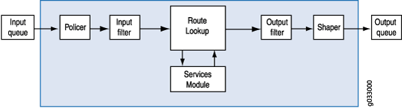
패킷이 디바이스에 들어가면 분류자, 필터 및 폴리서가 적용됩니다. 다음으로, 패킷의 송신 인터페이스는 경로 조회를 통해 결정됩니다. 패킷의 송신 인터페이스가 발견되면 필터가 적용되고 패킷이 송신 인터페이스로 전송되어 대기열에 배치되고 전송이 예약됩니다.
패킷 기반 포워딩은 주어진 연결에 속하는 이전 또는 후속 패킷에 대한 정보를 필요로 하지 않으며, 트래픽 허용 또는 거부에 대한 모든 결정은 패킷에 따라 다릅니다. 이 아키텍처는 개별 흐름이나 상태를 추적하지 않고 패킷을 전달하기 때문에 대규모 확장이 가능하다는 장점이 있습니다.
선택적 무상태 패킷 기반 서비스 이해
선택적 상태 비저장 패킷 기반 서비스를 사용하면 시스템에서 플로우 기반 및 패킷 기반 포워딩을 동시에 사용할 수 있습니다. 액세스 제어 목록(ACL)이라고도 하는 무상태 방화벽 필터를 사용하여 패킷 기반의 무상태 포워딩이 필요한 트래픽을 선택적으로 전달하여 스테이트풀 플로우 기반 포워딩을 피할 수 있습니다. 그렇게 전달되지 않은 트래픽은 기본 플로우 기반 포워딩 경로를 따릅니다. 플로우 기반 포워딩을 우회하는 것은 플로우 세션 확장 제약을 명시적으로 피하려는 트래픽에 유용할 수 있습니다.
기본적으로 Junos OS를 실행하는 주니퍼 네트웍스 보안 디바이스는 플로우 기반 포워딩을 사용합니다. 선택적 무상태 패킷 기반 서비스를 사용하면 입력 필터 용어에 따라 선택된 트래픽에 대해서만 패킷 기반 처리만 제공하도록 디바이스를 구성할 수 있습니다. 다른 트래픽은 플로우 기반 포워딩을 위해 처리됩니다. 플로우 기반 포워딩을 우회하는 것은 세션 확장 제약과 세션 생성 및 유지 관리 비용을 피하려는 구축에 유용합니다.
선택적 무상태 패킷 기반 처리를 위해 디바이스를 구성할 때, 시스템으로 유입되는 패킷은 특정 조건에 따라 다르게 처리됩니다.
패킷이 입력 필터 용어에 지정된 일치 조건을 충족하면 패킷 모드로 표시되고 구성된 모든 패킷 모드 기능이 적용됩니다. 플로우 기반 보안 기능은 적용되지 않습니다. 그것들을 우회합니다.
패킷이 패킷 모드로 플래그가 지정되지 않은 경우 정상적인 처리를 거칩니다. MPLS를 제외한 모든 서비스가 이 트래픽에 적용될 수 있습니다.
그림 2 는 플로우 기반 처리를 우회하는 선택적 상태 비저장 패킷 기반 서비스의 트래픽 플로우를 보여줍니다.
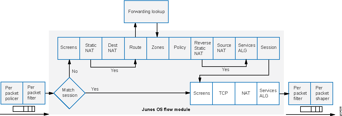 통한 트래픽 플로우
패킷이 인터페이스에 들어오면 인터페이스에 구성된 입력 패킷 필터가 적용됩니다.
패킷이 방화벽 필터
packet-mode에 지정된 조건과 일치하면 작업 수정자가 패킷에 설정됩니다. 패킷 모드 작업 수정자는 패킷 키 버퍼의 비트 필드를 업데이트합니다. 이 비트 필드는 플로우 기반 포워딩을 우회해야 하는지 여부를 결정하는 데 사용됩니다. 결과적으로, packet-mode action modifier가 있는 패킷은 플로우 기반 포워딩을 완전히 우회합니다. 패킷의 송신 인터페이스는 경로 조회를 통해 결정됩니다. 패킷의 송신 인터페이스가 발견되면 필터가 적용되고 패킷이 송신 인터페이스로 전송되어 대기열에 배치되고 전송이 예약됩니다.패킷이 이 필터 용어에 지정된 조건과 일치하지 않으면 필터에 구성된 다른 용어에 대해 평가됩니다. 모든 용어가 평가된 후에도 패킷이 필터의 용어와 일치하지 않으면 패킷은 자동으로 삭제됩니다. 패킷이 삭제되지 않도록 하려면 필터에서 모든 패킷을 수락하는 작업을 지정하는 용어를 구성합니다.
정의된 상태 비저장 서비스 집합은 선택적 무상태 패킷 기반 서비스와 함께 사용할 수 있습니다.
IPv4/IPv6 라우팅(유니캐스트 및 멀티캐스트 프로토콜)
CoS(Class of Service)
링크 단편화 및 인터리빙(LFI)
GRE(Generic routing encapsulation)
레이어 2 스위칭
MPLS(Multiprotocol Label Switching)
무상태 방화벽 필터
CRTP(Compressed Real-Time Transport Protocol)
MPLS 서비스가 필요한 트래픽은 패킷 모드에서 처리되어야 하지만, 일부 상황에서는 스테이트풀 검사, 네트워크 주소 변환(NAT) 및 IPsec과 같이 플로우 모드에서만 제공될 수 있는 특정 서비스를 이 트래픽에 동시에 적용해야 할 수도 있습니다. 시스템이 플로우 모드와 패킷 모드 모두에서 트래픽을 처리하도록 지시하려면 터널 인터페이스를 통해 연결된 여러 라우팅 인스턴스를 구성해야 합니다. 하나의 라우팅 인스턴스는 플로우 모드에서 패킷을 처리하도록 구성되어야 하고 다른 라우팅 인스턴스는 패킷 모드에서 패킷을 처리하도록 구성되어야 합니다. 터널 인터페이스를 사용하여 라우팅 인스턴스를 연결할 때, 해당 라우팅 인스턴스 간의 트래픽은 포워딩 경로에 다시 주입된 다음 다른 포워딩 방법을 사용하여 재처리될 수 있습니다.
선택적 상태 비저장 패킷 기반 서비스 구성 개요
이 기능은 SRX300, SRX320, SRX340, SRX345, vSRX 가상 방화벽 디바이스에서 지원됩니다. 액세스 제어 목록(ACL)이라고도 하는 무상태 방화벽 필터를 사용하여 선택적 무상태 패킷 기반 서비스를 구성합니다. 방화벽 필터에서 일치 조건을 지정하여 패킷 기반 포워딩을 위한 트래픽을 분류하고 작업을 지정하도록 작업 수정자를 구성 packet-mode 합니다. 일치 조건 및 작업이 정의되면 방화벽 필터가 관련 인터페이스에 적용됩니다.
방화벽 필터 구성 방법:
패킷이 인터페이스에 들어오면 인터페이스에 구성된 입력 패킷 필터가 적용됩니다. 패킷이 지정된 조건과 일치하고 packet-mode 작업이 구성된 경우, 패킷은 플로우 기반 포워딩을 완전히 우회합니다.
필터를 구성할 때는 방화벽 필터 내의 용어 순서에 유의해야 합니다. 패킷은 구성에 나열된 순서대로 각 용어에 대해 테스트됩니다. 일치하는 첫 번째 조건이 발견되면 작업 수정자가 포함되지 않는 한 next term 해당 용어와 연관된 작업이 패킷에 적용되고 방화벽 필터의 평가가 종료됩니다. 작업이 포함되어 있으면 next term 일치하는 패킷이 방화벽 필터의 다음 용어에 대해 평가되며, 그렇지 않으면 일치하는 패킷이 방화벽 필터의 후속 용어에 대해 평가되지 않습니다.
선택적 무상태 패킷 기반 서비스를 위한 방화벽 필터를 구성할 때:
불필요한 패킷 드롭을 방지하기 위해 플로우를 우회해야 하는 트래픽을 정확하게 식별합니다.
패킷 기반 플로우 경로와 관련된 모든 인터페이스에 패킷 모드 작업으로 방화벽 필터를 적용해야 합니다.
플로우 기반 포워딩을 사용하도록 호스트 바운드 TCP 트래픽을 구성해야 합니다. 작업 수정자를 포함하는
packet-mode방화벽 필터 용어에 대한 일치 조건을 지정할 때 이 트래픽을 제외합니다. 플로우를 우회하도록 구성된 모든 호스트 바운드 TCP 트래픽은 삭제됩니다. 비동기 플로우 모드 처리는 선택적 상태 비저장 패킷 기반 서비스에서 지원되지 않습니다.작업 수정자를 사용하여 입력 패킷 필터(출력이 아님)를 구성합니다
packet-mode.
중첩된 방화벽 필터(다른 필터의 용어 내에서 필터 구성)는 선택적 상태 비저장 패킷 기반 서비스에서 지원되지 않습니다.
선택적 무상태 패킷 기반 서비스를 구성할 수 있는 몇 가지 일반적인 구축 시나리오는 다음과 같습니다.
엔드 투 엔드 포워딩이 패킷 기반인 인트라넷 트래픽과 같은 프라이빗 LAN와 WAN 인터페이스 간의 트래픽 흐름
프라이빗 LAN과 그다지 안전하지 않은 WAN 인터페이스 간의 트래픽 흐름, 여기서 트래픽은 보안 트래픽과 그다지 안전하지 않은 트래픽에 대해 각각 패킷 기반 및 플로우 기반 포워딩을 사용합니다
프라이빗 LAN와 WAN 인터페이스 간의 트래픽 흐름은 프라이빗 WAN 링크가 다운되었을 때 플로우 기반 IPsec WAN로 페일오버됩니다.
플로우 기반 LAN에서 패킷 기반 MPLS WAN으로의 트래픽 플로우
예: 종단 간 패킷 기반 포워딩을 위한 선택적 무상태 패킷 기반 서비스 구성
이 예는 종단 간 패킷 기반 포워딩을 위해 선택적 무상태 패킷 기반 서비스를 구성하는 방법을 보여줍니다. 이 기능은 SRX300, SRX320, SRX340, SRX345, vSRX 가상 방화벽 디바이스에서 지원됩니다
요구 사항
시작하기 전에:
-
상태 비저장 방화벽 필터를 구성하는 방법을 이해합니다.
-
기본 연결을 구축합니다. .
개요
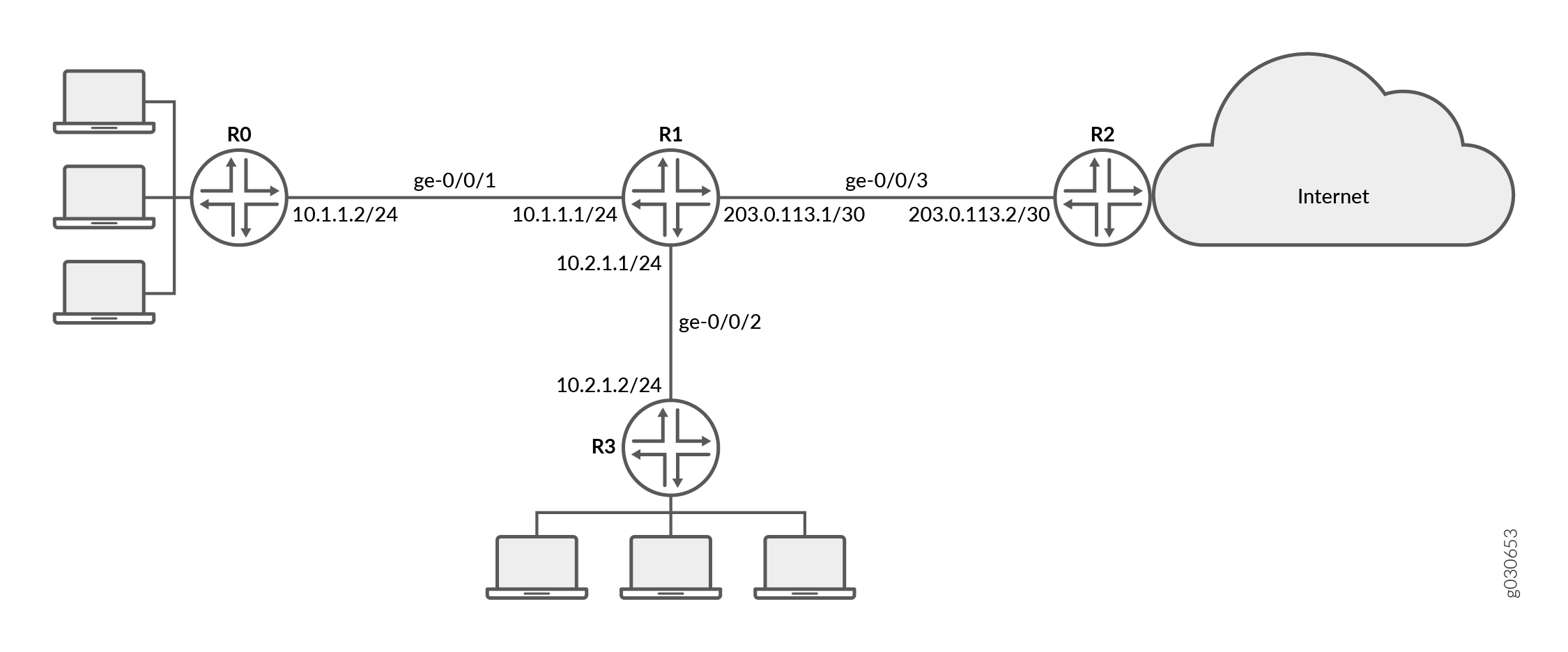
이 예에서는 각 디바이스의 인터페이스에 대한 IP 주소를 구성합니다. R0의 경우 10.1.1.2/24입니다. R1의 경우 10.1.1.1/24, 10.2.1.1/24 및 203.0.113.1/30입니다. R2의 경우 203.0.113.2/30입니다. R3의 경우 10.2.1.2/24입니다. 다음과 같이 고정 경로를 생성하고 디바이스에 대한 다음 홉 주소를 연결합니다. R0은 10.1.1.2, R1은 198.51.100.2, R2는 203.0.113.1, R3은 10.2.1.1입니다.
그런 다음 디바이스 R1에서 untrust라는 영역을 구성하고 인터페이스 ge-0/0/3에 할당합니다. 또한 trust라는 영역을 생성하고 여기에 인터페이스 ge-0/0/1 및 ge-0/0/2를 할당합니다. 신뢰 및 신뢰할 수 없는 영역을 구성하여 지원되는 모든 애플리케이션 서비스를 인바운드 서비스로 허용합니다. 모든 소스 주소, 대상 주소 및 애플리케이션의 트래픽이 영역 사이를 통과하도록 허용합니다.
그런 다음 방화벽 필터 bypass-flow-filter를 생성하고, 내부 인터페이스 ge-0/0/1과 ge-0/0/2 사이의 트래픽과 일치시키고 packet-mode action modifier를 포함하는 bypass-flow-term-1 및 bypass-flow-term-2라는 용어를 정의합니다. 나머지 모든 트래픽을 수락하기 위해 accept-rest 용어를 정의합니다. 마지막으로, 방화벽 필터 bypass-flow-filter를 내부 인터페이스 ge-0/0/1 및 ge-0/0/2(외부 인터페이스가 아님)에 적용합니다. 그 결과 모든 내부 트래픽은 플로우 기반 포워딩을 우회하고 인터넷에서 송수신되는 트래픽은 플로우 기반 포워딩을 우회하지 않습니다.
그림 3 은 이 예에서 사용되는 네트워크 토폴로지를 보여줍니다.
 사용한 인트라넷 트래픽
회사의 브랜치 오피스는 프라이빗 WAN을 통해 서로 연결되어 있습니다. 이 내부 트래픽의 경우 보안이 문제가 되지 않으므로 패킷 전달이 필요합니다. 따라서 이 트래픽의 경우 플로우 기반 포워딩을 우회하도록 선택적 무상태 패킷 기반 서비스를 구성하기로 결정합니다. 인터넷을 오가는 나머지 트래픽은 플로우 기반 포워딩을 사용합니다.
구성
절차
CLI 빠른 구성
이 예를 빠르게 구성하려면, 아래 명령을 복사하여 텍스트 파일로 붙여 넣은 다음 모든 라인브레이크를 제거하고, 네트워크 구성을 일치하는 데 필요한 세부 사항을 변경한 다음, 계층 수준에서 [edit] 명령을 복사하여 CLI에 붙여 넣은 다음, 구성 모드에서 들어갑니다 commit .
{device R0}
[edit]
set interfaces ge-0/0/1 description "Internal 1" unit 0 family inet address 10.1.1.2/24
set routing-options static route 0.0.0.0/0 next-hop 10.1.1.1
{device R1}
set interfaces ge-0/0/1 description "Internal 1" unit 0 family inet address 10.1.1.1/24
set interfaces ge-0/0/2 description "Internal 2" unit 0 family inet address 10.2.1.1/24
set interfaces ge-0/0/3 description "Internet" unit 0 family inet address 203.0.113.1/30
set routing-options static route 0.0.0.0/0 next-hop 203.0.113.2
set security zones security-zone untrust interfaces ge-0/0/3
set security zones security-zone trust interfaces ge-0/0/1
set security zones security-zone trust interfaces ge-0/0/2
set security zones security-zone trust host-inbound-traffic system-services all
set security zones security-zone untrust host-inbound-traffic system-services all
set security policies from-zone trust to-zone untrust policy Internet-traffic match source-address any destination-address any application any
set security policies from-zone trust to-zone untrust policy Internet-traffic then permit
set security policies from-zone untrust to-zone trust policy Incoming-traffic match source-address any destination-address any application any
set security policies from-zone untrust to-zone trust policy Incoming-traffic then permit
set security policies from-zone trust to-zone trust policy Intrazone-traffic match source-address any destination-address any application any
set security policies from-zone trust to-zone trust policy Intrazone-traffic then permit
set firewall family inet filter bypass-flow-filter term bypass-flow-term-1 from source-address 10.1.1.0/24
set firewall family inet filter bypass-flow-filter term bypass-flow-term–1 from destination-address 10.2.1.0/24
set firewall family inet filter bypass-flow-filter term bypass-flow-term-1 then packet-mode
set firewall family inet filter bypass-flow-filter term bypass-flow-term-2 from source-address 10.2.1.0/24
set firewall family inet filter bypass-flow-filter term bypass-flow-term-2 from destination-address 10.1.1.0/24
set firewall family inet filter bypass-flow-filter term bypass-flow-term-2 then packet-mode
set firewall family inet filter bypass-flow-filter term accept-rest then accept
set interfaces ge-0/0/1 description "Internal 1" unit 0 family inet filter input bypass-flow-filer
set interfaces ge-0/0/2 description "Internal 2" unit 0 family inet filter input bypass-flow-filer
{device R2}
set interfaces ge-0/0/3 description "Internet" unit 0 family inet address 10.1.1.2/30
set routing-options static route 0.0.0.0/0 next-hop 10.1.1.1
{device R3}
[edit]
set interfaces ge-0/0/2 description "Internal 2" unit 0 family inet address 10.2.1.2/24
set routing-options static route 0.0.0.0/0 next-hop 10.2.1.1
단계별 절차
다음 예에서는 구성 계층에서 다양한 수준을 탐색해야 합니다. 이를 수행하는 방법에 대한 지침은 CLI 사용자 가이드의 구성 모드에서 CLI 편집기 사용을 참조하십시오.
종단 간 패킷 기반 포워딩을 위한 선택적 상태 비저장 패킷 기반 서비스를 구성하려면 다음을 수행합니다.
-
디바이스 R0, R1, R2 및 R3의 인터페이스에 대한 IP 주소를 구성합니다.
{device R0} [edit] user@host#set interfaces ge-0/0/1 description "Internal 1" unit 0 family inet address 10.1.1.2/24{device R1} [edit] user@host#set interfaces ge-0/0/1 description "Internal 1" unit 0 family inet address 10.1.1.1/24user@host#set interfaces ge-0/0/2 description "Internal 2" unit 0 family inet address 10.2.1.1/24user@host#set interfaces ge-0/0/3 description "Internet" unit 0 family inet address 203.0.113.1/30{device R2} [edit] user@host#set interfaces ge-0/0/3 description "Internet" unit 0 family inet address 203.0.113.1/30{device R3} [edit] user@host#set interfaces ge-0/0/2 description "Internal 2" unit 0 family inet address 10.2.1.2/24 -
정적 경로를 생성하고 디바이스 R0, R1, R2 및 R3에 적합한 다음 홉 주소를 연결합니다.
{device R0} [edit] user@host#set routing-options static route 0.0.0.0/0 next-hop 10.1.1.1{device R1} [edit] user@host#set routing-options static route 0.0.0.0/0 next-hop 203.0.113.1{device R2} [edit] user@host#set routing-options static route 0.0.0.0/0 next-hop 203.0.113.2{device R3} [edit] user@host#set routing-options static route 0.0.0.0/0 next-hop 10.2.1.1 -
보안 영역을 구성하고 인터페이스를 할당합니다.
{device R1} [edit] user@host#set security zones security-zone untrust interfaces ge-0/0/3user@host#set security zones security-zone trust interfaces ge-0/0/1user@host#set security zones security-zone trust interfaces ge-0/0/2 -
영역에 대한 애플리케이션 서비스를 구성합니다.
{device R1} [edit] user@host#set security zones security-zone trust host-inbound-traffic system-services alluser@host#set security zones security-zone untrust host-inbound-traffic system-services all -
보안 정책 구성
{device R1} [edit] user@host#set security policies from-zone trust to-zone untrust policy Internet-traffic match source-address any destination-address any application anyuser@host#set security policies from-zone trust to-zone untrust policy Internet-traffic then permituser@host#set security policies from-zone untrust to-zone trust policy Incoming-traffic match source-address any destination-address any application anyuser@host#set security policies from-zone untrust to-zone trust policy Incoming-traffic then permituser@host#set security policies from-zone trust to-zone trust policy Intrazone-traffic match source-address any destination-address any application anyuser@host#set security policies from-zone trust to-zone trust policy Intrazone-traffic then permit -
방화벽 필터를 생성하고 모든 패킷 기반 포워딩 트래픽에 대한 용어를 정의합니다.
{device R1} [edit] user@host#set firewall family inet filter bypass-flow-filter term bypass-flow-term-1 from source-address 10.1.1.0/24user@host#set firewall family inet filter bypass-flow-filter term bypass-flow-term–1 from destination-address 10.2.1.0/24user@host#set firewall family inet filter bypass-flow-filter term bypass-flow-term-1 then packet-modeuser@host#set firewall family inet filter bypass-flow-filter term bypass-flow-term-2 from source-address 10.2.1.0/24user@host#set firewall family inet filter bypass-flow-filter term bypass-flow-term-2 from destination-address 10.1.1.0/24user@host#set firewall family inet filter bypass-flow-filter term bypass-flow-term-2 then packet-mode -
나머지 트래픽에 대한 다른 용어를 지정합니다.
{device R1} [edit] user@host#set firewall family inet filter bypass-flow-filter term accept-rest then accept -
관련 인터페이스에 방화벽 필터를 적용합니다.
{device R1} [edit] user@host#set interfaces ge-0/0/1 description "Internal 1" unit 0 family inet filter input bypass-flow-fileruser@host#set interfaces ge-0/0/2 description "Internal 2" unit 0 family inet filter input bypass-flow-filer
결과
구성 모드에서 , show routing-options및 show firewall 명령을 show interfaces입력하여 구성을 확인합니다. 출력에 의도한 구성이 표시되지 않으면 이 예의 구성 지침을 반복하여 수정합니다.
{device R0}
[edit]
user@host# show interfaces
ge-0/0/1 {
    description “Internal 1”
    unit 0 {
        family inet {
            address 10.1.1.2/24
        }
    }
}
{device R0}
[edit]
user@host# show routing-options
static {
    route 0.0.0.0/0 next-hop 10.1.1.1;
}
{device R2}
[edit]
user@host# show interfaces
ge-0/0/3 {
    description “Internet”
    unit 0 {
        family inet {
            address 203.0.113.2/30;
        }
    }
}
{device R2}
[edit]
user@host# show routing-options
static {
    route 0.0.0.0/0 next-hop 203.0.113.1;
}
{device R3}
[edit]
user@host# show interfaces
ge-0/0/2 {
    description “Internal 2”
    unit 0 {
        family inet {
            address 10.2.1.2/24;
        }
    }
}
{device R3}
user@host# show routing-options
static {
    route 0.0.0.0/0 next-hop 10.2.1.1;
}
{device R1}
[edit]
user@host# show interfaces
ge-0/0/1 {
    description “internal 1”
    unit 0 {
        family inet {
            filter {
                input bypass-flow-filter;
                }
            address 10.1.1.1/24;
        }
    }
}
ge-0/0/2 {
    description “Internal 2”
    unit 0 {
        family inet {
            filter {
                input bypass-flow-filter;
                }
            address 10.2.1.1/24;
        }
    }
}
ge-0/0/3 {
    description “Internet”
    unit 0 {
        family inet {
            address 203.0.113.1/30;
        }
    }
}
{device R1}
[edit]
user@host# show routing-options
static {
    route 0.0.0.0/0 next-hop 203.0.113.1;
}
{device R1}
[edit]
user@host# show firewall
family inet {
    filter bypass-flow-filter {
        term bypass-flow-term-1 {
            from {
                source-address {
                    10.1.1.0/24;
                }
                destination-address {
                    10.2.1.0/24;
                }
            }
            then packet-mode;
        }
        term bypass-flow-term-2 {
            from {
                source-address {
                    10.2.1.0/24;
                }
                destination-address {
                    10.1.1.0/24;
                }
            }
            then packet-mode;
        }
        term accept-rest {
            then accept;
        }
    }
}
디바이스 구성이 완료되면 구성 모드에서 들어갑니다 commit .
검증
구성이 제대로 작동하고 있는지 확인합니다.
엔드 투 엔드 패킷 기반 구성 확인
목적
선택적 무상태 패킷 기반 서비스가 구성되었는지 확인합니다.
작업
구성 모드에서 , show routing-options, , show security policiesshow security zones및 명령을 show firewall 입력합니다show interfaces.
출력이 방화벽 필터, 인터페이스 및 정책의 의도된 구성을 보여주는지 확인합니다.
패킷을 테스트하려는 순서대로 용어가 나열되어 있는지 확인합니다. 명령을 사용하여 방화벽 필터 내에서 용어를 이동할 수 있습니다.insert
인트라넷 트래픽에서 세션 설정 확인
목적
트래픽이 인트라넷 내의 인터페이스로 전송될 때 세션이 설정되는지 확인합니다.
작업
세션이 설정되었는지 확인하려면 다음 작업을 수행합니다.
-
디바이스
R1에서 운영 모드clear security flow session all명령을 입력하여 기존의 모든 보안 플로우 세션을 지웁니다. -
디바이스
R0에서 운영 모드ping명령을 입력하여 디바이스R3로 트래픽을 전송합니다. -
디바이스
R1에서 트래픽이 디바이스R0에서 통해R1전송되는R3디바이스에서 운영 모드show security flow session명령을 입력합니다.Flow Sessions on FPC10 PIC1: Total sessions: 0 Flow Sessions on FPC10 PIC2: Total sessions: 0 Flow Sessions on FPC10 PIC3: Total sessions: 0
설정된 세션을 확인하려면 명령이 패킷을 송수신하는 동안 ping 명령을 입력 show security flow session 해야 합니다.
{device R0}
user@host> ping 203.0.113.6
PING 203.0.113.6 (203.0.113.6): 56 data bytes 64 bytes from 203.0.113.6: icmp_seq=0 ttl=63 time=2.326 ms 64 bytes from 203.0.113.6: icmp_seq=1 ttl=63 time=2.569 ms 64 bytes from 203.0.113.6: icmp_seq=2 ttl=63 time=2.565 ms 64 bytes from 203.0.113.6: icmp_seq=3 ttl=63 time=2.563 ms 64 bytes from 203.0.113.6: icmp_seq=4 ttl=63 time=2.306 ms 64 bytes from 203.0.113.6: icmp_seq=5 ttl=63 time=2.560 ms 64 bytes from 203.0.113.6: icmp_seq=6 ttl=63 time=4.130 ms 64 bytes from 203.0.113.6: icmp_seq=7 ttl=63 time=2.316 ms ...
{device R1}
user@host> show security flow session
Flow Sessions on FPC10 PIC1:
Total sessions: 0

Flow Sessions on FPC10 PIC2:
Total sessions: 0

Flow Sessions on FPC10 PIC3:
Total sessions: 0
출력은 에서 R0 로 R3 전송되는 트래픽을 보여주며 세션이 설정되지 않은 것을 보여줍니다. 이 예에서는 인터페이스 Internal 2 Internal 1 와 회사의 인트라넷 트래픽에 대해 작업을 수정자와 함께 packet-mode 적용 bypass-flow-filter 했습니다. 이 출력은 두 인터페이스 간의 트래픽이 플로우 기반 포워딩을 올바르게 우회하고 있으므로 세션이 설정되지 않는지 확인합니다.
인터넷 트래픽에 대한 세션 설정 확인
목적
트래픽이 인터넷으로 전송될 때 세션이 설정되는지 확인합니다.
작업
인터넷에 대한 트래픽이 플로우 기반 포워딩을 사용하고 세션이 설정되었는지 확인하려면 다음 작업을 수행합니다.
-
디바이스
R1에서 운영 모드clear security flow session all명령을 입력하여 기존의 모든 보안 플로우 세션을 지웁니다. -
디바이스
R0에서 운영 모드ping명령을 입력하여 디바이스R2로 트래픽을 전송합니다. -
디바이스
R1에서 트래픽이 전송되는R0R2상태에서 운영R1모드show security flow session명령을 입력합니다.
설정된 세션을 확인하려면 명령이 패킷을 송수신하는 동안 ping 명령을 입력 show security flow session 해야 합니다.
{device R0}
user@host> ping 10.2.1.2 -c 10
PING 10.2.1.2 (10.2.1.2) 56(84) bytes of data. 64 bytes from 10.2.1.2: icmp_seq=1 ttl=63 time=6.07 ms 64 bytes from 10.2.1.2: icmp_seq=2 ttl=63 time=4.24 ms 64 bytes from 10.2.1.2: icmp_seq=3 ttl=63 time=2.85 ms 64 bytes from 10.2.1.2: icmp_seq=4 ttl=63 time=6.14 ms ...
{device R1}
user@host>show security flow session
Flow Sessions on FPC10 PIC1: Session ID: 410000077, Policy name: Internet-traffic/5, Timeout: 2, Valid In: 10.1.1.2/3 --> 10.2.1.2/32055;icmp, If: ge-0/0/1.0, Pkts: 1, Bytes: 84, CP Session ID: 410000198 Out: 10.2.1.2/32055 --> 10.1.1.2/3;icmp, If: ge-0/0/2.0, Pkts: 1, Bytes: 84, CP Session ID: 410000198 Total sessions: 1 Flow Sessions on FPC10 PIC2: Session ID: 420000079, Policy name: Internet-traffic/5, Timeout: 2, Valid In: 10.1.1.2/5 --> 10.2.1.2/32055;icmp, If: ge-0/0/1.0, Pkts: 1, Bytes: 84, CP Session ID: 420000163 Out: 10.2.1.2/32055 --> 10.1.1.2/5;icmp, If: ge-0/0/2.0, Pkts: 1, Bytes: 84, CP Session ID: 420000163 Total sessions: 1 Flow Sessions on FPC10 PIC3: Session ID: 430000090, Policy name: Internet-traffic/5, Timeout: 4, Valid In:10.1.1.2/7 --> 10.2.1.2/32055;icmp, If: ge-0/0/1.0, Pkts: 1, Bytes: 84, CP Session ID: 430000088 Out: 10.2.1.2/32055 --> 10.1.1.2/7;icmp, If: ge-0/0/2.0, Pkts: 1, Bytes: 84, CP Session ID: 430000088 Total sessions: 1
출력은 디바이스 R0 에서 설정된 세션으로 R1 전송되는 트래픽을 보여줍니다. 이 예에서는 회사의 인터넷 트래픽에 대해 인터페이스 Internet 에서 작업 수정자를 포함 packet-mode 하지 bypass-flow-filter 않았습니다. 이 출력은 인터넷에 대한 트래픽이 플로우 기반 포워딩을 올바르게 사용하고 있음을 확인하므로 세션이 설정됩니다.
디바이스 R3 R2 에서 트래픽을 전송하고 이 섹션의 명령을 사용하여 설정된 세션을 확인합니다.
예: 패킷 기반에서 플로우 기반 포워딩을 위한 선택적 무상태 패킷 기반 서비스 구성
이 예는 패킷 기반에서 플로우 기반 포워딩을 위해 선택적 무상태 패킷 기반 서비스를 구성하는 방법을 보여줍니다. 이 기능은 SRX300, SRX320, SRX340, SRX345, vSRX 가상 방화벽 디바이스에서 지원됩니다.
요구 사항
시작하기 전에:
-
상태 비저장 방화벽 필터를 구성하는 방법을 이해합니다.
-
기본 연결을 구축합니다. .
개요
이 예에서는 각 디바이스의 인터페이스에 대한 IP 주소를 구성합니다. 디바이스 R0의 경우 198.51.100.9/24로; R1의 경우 are198.51.100.10/24 및 203.0.113.5/24; R2의 경우 203.0.113.9/24입니다. 디바이스 R1에서 라우팅 인스턴스 간에 내부 서비스 인터페이스 lt-0/0/0을 설정하고 두 가상 디바이스 간의 피어 관계를 구성합니다. 그런 다음 두 개의 보안 영역인 Primary-VR-zone 및 Internet-VR-zone을 생성하고, 관련 인터페이스를 할당하고, 지원되는 모든 애플리케이션 및 프로토콜을 허용하도록 구성합니다.
그런 다음 정책을 구성하고 모든 패킷이 허용되도록 지정합니다. 가상 디바이스 라우팅 인스턴스 Internet-VR을 구성하고 플로우 기반 포워딩을 위한 인터페이스를 할당합니다. 디바이스 R0, R1 및 R2에서 최단 경로 우선(OSPF)을 활성화합니다. 디바이스 R2에서 packet-mode 작업 수정자를 포함하는 bypass-flow-term이라는 용어를 사용하여 filter bypass-flow-filter를 구성합니다. 일치 조건을 지정하지 않았으므로 이 필터는 적용된 인터페이스를 통과하는 모든 트래픽에 적용됩니다.
마지막으로, 디바이스 R1에서 방화벽 필터 bypass-flow-filter를 내부 인터페이스 ge-0/0/2.0 및 lt-0/0/0.0에 적용합니다. Internet-VR 라우팅 인스턴스와 연결된 인터페이스에는 필터를 적용하지 않습니다. 그 결과, 기본 라우팅 인스턴스와 연결된 LAN 인터페이스를 통과하는 모든 트래픽은 패킷 기반 포워딩을 사용하고 Internet-VR 라우팅 인스턴스를 통과하는 모든 트래픽은 플로우 기반 포워딩을 사용합니다.
그림 4 는 이 예에서 사용된 네트워크 토폴로지를 보여줍니다.
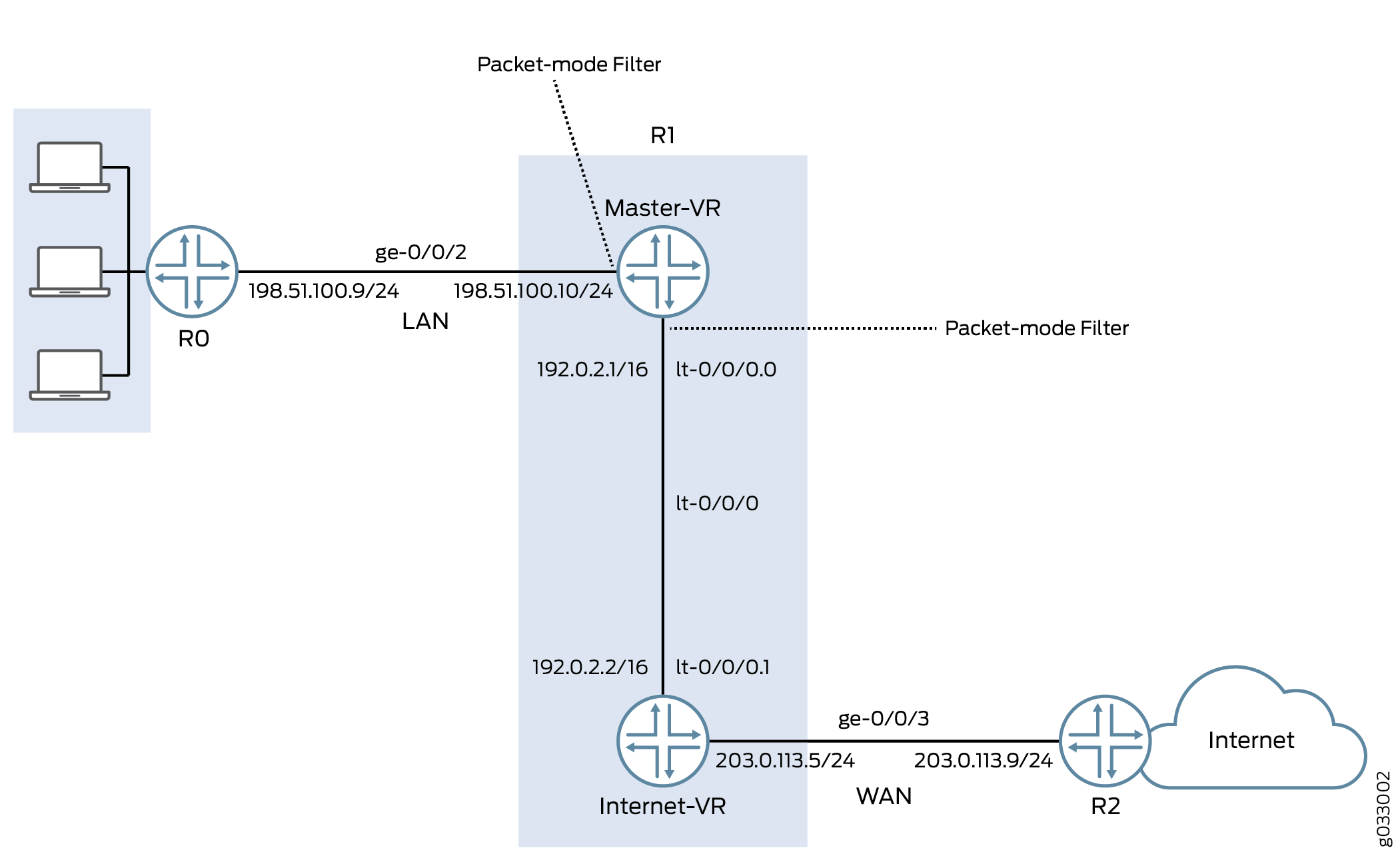
프라이빗 LAN을 향하는 인터페이스에는 보안 서비스가 필요하지 않지만 WAN을 향하는 인터페이스에는 보안이 필요합니다. 이 예에서는 패킷 기반 포워딩을 처리하는 것과 플로우 기반 포워딩을 처리하는 두 개의 라우팅 인스턴스를 구성하여 안전하고 안전하지 않은 트래픽에 대해 패킷 기반 및 플로우 기반 포워딩을 모두 구성하기로 결정합니다.
구성
절차
CLI 빠른 구성
이 예를 빠르게 구성하려면, 아래 명령을 복사하여 텍스트 파일로 붙여 넣은 다음 모든 라인브레이크를 제거하고, 네트워크 구성을 일치하는 데 필요한 세부 사항을 변경한 다음, 계층 수준에서 [edit] 명령을 복사하여 CLI에 붙여 넣은 다음, 구성 모드에서 들어갑니다 commit .
{device R0}
set interfaces description “Connect to Primary VR” ge-0/0/2 unit 0 family inet address 198.51.100.9/24
set protocols ospf area 0.0.0.0 interface ge-0/0/2.0
{device R1}
set interfaces description “Connect to R0” ge-0/0/2 unit 0 family inet address 198.51.100.10/24
set interfaces description “Connect to R2” ge-0/0/3 unit 0 family inet address 203.0.113.5/24
set interfaces lt-0/0/0 unit 0 encapsulation frame-relay dlci 100 peer-unit 1 family inet address 192.0.2.1/16
set interfaces lt-0/0/0 unit 1 encapsulation frame-relay dlci 100 peer-unit 0 family inet address 192.0.2.2/16
set security zones security-zone Primary-VR-zone host-inbound-traffic system-services all
set security zones security-zone Primary-VR-zone host-inbound-traffic protocols all
set security zones security-zone Primary-VR-zone interfaces ge-0/0/2.0
set security zones security-zone Primary-VR-zone interfaces lt-0/0/0.0
set security zones security-zone Internet-VR-zone host-inbound-traffic system-services all
set security zones security-zone Internet-VR-zone host-inbound-traffic protocols all
set security zones security-zone Internet-VR-zone interfaces ge-0/0/3.0
set security zones security-zone Internet-VR-zone interfaces lt-0/0/0.1
set security policies default-policy permit-all
set routing-instances Internet-VR instance-type virtual-router interface lt-0/0/0.1
set routing-instances Internet-VR instance-type virtual-router interface ge-0/0/3.0
set protocols ospf area 0.0.0.0 interface ge-0/0/2.0
set protocols ospf area 0.0.0.0 interface lt-0/0/0.0
set routing-instances Internet-VR protocols ospf area 0.0.0.0 interface lt-0/0/0.1
set routing-instances Internet-VR protocols ospf area 0.0.0.0 interface ge-0/0/3.0
set firewall family inet filter bypass-flow-filter term bypass-flow-term then accept
set firewall family inet filter bypass-flow-filter term bypass-flow-term then packet-mode
set interfaces ge-0/0/2 unit 0 family inet filter input bypass-flow-filter
set interfaces lt-0/0/0 unit 0 family inet filter input bypass-flow-filter
{device R2}
set interfaces description “Connect to Internet-VR” ge-0/0/3 unit 0 family inet address 203.0.113.9/24
set protocols ospf area 0.0.0.0 interface ge-0/0/3
단계별 절차
다음 예에서는 구성 계층에서 다양한 수준을 탐색해야 합니다. 이를 수행하는 방법에 대한 지침은 CLI 사용자 가이드의 구성 모드에서 CLI 편집기 사용을 참조하십시오.
종단 간 패킷 기반 포워딩을 위한 선택적 상태 비저장 패킷 기반 서비스를 구성하려면 다음을 수행합니다.
-
인터페이스의 IP 주소를 구성합니다.
{device R0} [edit] user@host#set interfaces description “Connect to Primary VR” ge-0/0/2 unit 0 family inet address 198.51.100.9/24{device R1} [edit] user@host#set interfaces description “Connect to R0” ge-0/0/2 unit 0 family inet address 198.51.100.10/24user@host#set interfaces description “Connect to R2” ge-0/0/3 unit 0 family inet address 203.0.113.5/24{device R2} [edit] user@host#set interfaces description “Connect to Internet-VR” ge-0/0/3 unit 0 family inet address 203.0.113.9/24 -
라우팅 인스턴스 간에 내부 서비스 인터페이스를 설정합니다.
{device R1} [edit] user@host#set interfaces lt-0/0/0 unit 0 encapsulation frame-relay dlci 100 peer-unit 1 family inet address 192.0.2.1/16user@host#set interfaces lt-0/0/0 unit 1 encapsulation frame-relay dlci 100 peer-unit 0 family inet address 192.0.2.2/16 -
보안 영역을 구성합니다.
{device R1} [edit] user@host#set security zones security-zone Primary-VR-zone host-inbound-traffic system-services alluser@host#set security zones security-zone Primary-VR-zone host-inbound-traffic protocols alluser@host#set security zones security-zone Primary-VR-zone interfaces ge-0/0/2.0user@host#set security zones security-zone Primary-VR-zone interfaces lt-0/0/0.0user@host#set security zones security-zone Internet-VR-zone host-inbound-traffic system-services alluser@host#set security zones security-zone Internet-VR-zone host-inbound-traffic protocols alluser@host#set security zones security-zone Internet-VR-zone interfaces ge-0/0/3.0user@host#set security zones security-zone Internet-VR-zone interfaces lt-0/0/0.1 -
정책을 구성합니다.
{device R1} [edit] user@host#set security policies default-policy permit-all -
가상 디바이스 라우팅 인스턴스를 구성합니다.
{device R1} [edit] user@host#set routing-instances Internet-VR instance-type virtual-router interface lt-0/0/0.1user@host#set routing-instances Internet-VR instance-type virtual-router interface ge-0/0/3.0 -
네트워크의 모든 인터페이스에서 OSPF를 활성화합니다.
{device R0} [edit] user@host#set protocols ospf area 0.0.0.0 interface ge-0/0/2.0{device R1 for Primary-VR} [edit] user@host#set protocols ospf area 0.0.0.0 interface ge-0/0/2.0user@host#set protocols ospf area 0.0.0.0 interface lt-0/0/0.0{device R1 for Internet-VR} [edit] user@host#set routing-instances Internet-VR protocols ospf area 0.0.0.0 interface lt-0/0/0.1user@host#set routing-instances Internet-VR protocols ospf area 0.0.0.0 interface ge-0/0/3.0{device R2} [edit] user@host#set protocols ospf area 0.0.0.0 interface ge-0/0/3 -
방화벽 필터를 생성하고 패킷 기반 포워딩 트래픽에 대한 용어를 정의합니다.
{device R1} [edit] user@host#set firewall family inet filter bypass-flow-filter term bypass-flow-term then acceptuser@host#set firewall family inet filter bypass-flow-filter term bypass-flow-term then packet-mode -
관련 인터페이스에 방화벽 필터를 적용합니다.
{device R1} [edit] user@host#set interfaces ge-0/0/2 unit 0 family inet filter input bypass-flow-filteruser@host#set interfaces lt-0/0/0 unit 0 family inet filter input bypass-flow-filter
결과
구성 모드에서 , show protocols, show security, show routing-instances및 show firewall 명령을 show interfaces입력하여 구성을 확인합니다. 출력에 의도한 구성이 표시되지 않으면 이 예의 구성 지침을 반복하여 수정합니다.
{device R0}
[edit]
user@host# show interfaces
ge-0/0/2 {
description “Connect to Primary-VR”
unit 0 {
family inet {
address 198.51.100.9/24
}
}
}
{device R0}
[edit]
user@host# show protocols
ospf {
area 0.0.0.0/0 {
interface ge-0/0/2.0;
}
}
{device R2}
[edit]
user@host# show interfaces
ge-0/0/3 {
description “Connect to Internet-VR”
unit 0 {
family inet {
address 203.0.113.9/24;
}
}
}
{device R2}
[edit]
user@host# show protocols
ospf {
area 0.0.0.0/0 {
interface ge-0/0/3.0;
}
}
{device R1}
[edit]
user@host# show interfaces
ge-0/0/2 {
description “Connect to R0”
unit 0 {
family inet {
filter {
input bypass-flow-filter;
}
address 198.51.100.10/24;
}
}
}
lt-0/0/0 {
unit 0 {
encapsulation frame-relay;
dlci 100;
peer-unit 1;
family inet {
filter {
input bypass-flow-filter
}
address 192.0.2.1/16;
}
}
unit 1{
encapsulation frame-relay;
dlci 100;
peer-unit 0;
family inet {
address 192.0.2.2/16 ;
}
}
}
{device R1}
[edit]
user@host# show protocols
ospf {
area 0.0.0.0/0 {
interface ge-0/0/2.0;
interface lt-0/0/0.0;
}
}
{device R1}
[edit]
user@host# show firewall
filter bypass-flow-filter {
term bypass-flow-term {
then {
packet-mode;
accept;
}
}
}
{device R1}
[edit]
user@host# show routing-instances
Internet-VR {
instance-type virtual-router;
interface lt-0/0/0.1;
interface ge-0/0/3.0;
protocols {
ospf {
area 0.0.0.0 {
interface ge-0/0/3.0;
lt-0/0/0.1;
}
}
}
}
{device R1}
[edit]
user@host# show security
security zone Primary-VR-zone {
host-inbound-traffic {
system-services {
all;
{
protocols {
all;
{
{
intefaces {
ge-0/0/2.0;
lt-0/0/0.0;
{
{
security zone Internet-VR-zone {
host-inbound-traffic {
system-services {
all;
{
protocols {
all;
}
}
intefaces {
ge-0/0/3.0;
lt-0/0/0.1;
{
{
policies {
default-policy {
permit-all;
}
}
디바이스 구성이 완료되면 구성 모드에서 들어갑니다 commit .
검증
구성이 제대로 작동하고 있는지 확인합니다.
패킷 기반에서 플로우 기반 구성 확인
목적
선택적 상태 비저장 패킷 기반 서비스가 패킷 기반에서 플로우 기반 포워딩으로 구성되었는지 확인합니다.
작업
구성 모드에서 , show protocols, , show routing-instancesshow security및 명령을 show firewall 입력합니다show interfaces.
출력이 방화벽 필터, 라우팅 인스턴스, 인터페이스 및 정책의 의도된 구성을 보여주는지 확인합니다.
패킷을 테스트하려는 순서대로 용어가 나열되어 있는지 확인합니다. 명령을 사용하여 방화벽 필터 내에서 용어를 이동할 수 있습니다.insert
LAN 트래픽에서 세션 설정 확인
목적
트래픽이 LAN 내의 인터페이스에서 전송될 때 세션이 설정되는지 확인합니다.
작업
세션이 설정되었는지 확인하려면 다음 작업을 수행합니다.
-
디바이스
R1에서 운영 모드에서 명령을 입력하여 기존의clear security flow session all모든 보안 플로우 세션을 지웁니다. -
디바이스
R0에서 운영 모드에서 디바이스로 트래픽을 전송하는 명령을 입력합니다ping.Primary-VR -
디바이스
R1에서 트래픽이 전송되는R0디바이스에서, 를 통해R1운영 모드에서 명령을 입력합니다show security flow session.
설정된 세션을 확인하려면 명령이 패킷을 송수신하는 동안 ping 명령을 입력 show security flow session 해야 합니다.
{device R0}
user@host> ping 192.0.2.1
PING 192.0.2.1 (192.0.2.1): 56 data bytes 64 bytes from 192.0.2.1: icmp_seq=0 ttl=63 time=2.208 ms 64 bytes from 192.0.2.1: icmp_seq=1 ttl=63 time=2.568 ms 64 bytes from 192.0.2.1: icmp_seq=2 ttl=63 time=2.573 ms 64 bytes from 192.0.2.1: icmp_seq=3 ttl=63 time=2.310 ms 64 bytes from 192.0.2.1: icmp_seq=4 ttl=63 time=1.566 ms 64 bytes from 192.0.2.1: icmp_seq=5 ttl=63 time=1.569 ms ...
{device R1}
user@host> show security flow session
0 sessions displayed
출력은 에서 R0 로 Primary-VR 전송되는 트래픽을 보여주며 세션이 설정되지 않은 것을 보여줍니다. 이 예에서는 인터페이스 ge-0/0/0 lt-0/0/0.0 와 회사의 LAN 트래픽에 대해 작업을 수정자와 함께 packet-mode 적용 bypass-flow-filter 했습니다. 이 출력은 두 인터페이스 간의 트래픽이 플로우 기반 포워딩을 올바르게 우회하고 있으므로 세션이 설정되지 않는지 확인합니다.
인터넷 트래픽에 대한 세션 설정 확인
목적
트래픽이 인터넷으로 전송될 때 세션이 설정되는지 확인합니다.
작업
인터넷에 대한 트래픽이 플로우 기반 포워딩을 사용하고 세션이 설정되었는지 확인하려면 다음 작업을 수행합니다.
-
디바이스
R1에서 운영 모드에서 명령을 입력하여 기존의clear security flow session all모든 보안 플로우 세션을 지웁니다. -
디바이스
R0에서 운영 모드에서 디바이스로 트래픽을 전송하는 명령을 입력합니다ping.R2 -
디바이스
R1에서 에서 로R1R2트래픽이 전송되는R0상태에서 작동 모드에서 명령을show security flow session입력합니다.root@host> show security flow session Flow Sessions on FPC10 PIC1: Total sessions: 0 Flow Sessions on FPC10 PIC2: Total sessions: 0 Flow Sessions on FPC10 PIC3: Total sessions: 0
설정된 세션을 확인하려면 명령이 패킷을 송수신하는 동안 ping 명령을 입력 show security flow session 해야 합니다.
{device R0}
user@host> ping 192.0.2.1 -c 10
PING 60.0.0.1 (60.0.0.1) 56(84) bytes of data. 64 bytes from 192.0.2.1: icmp_seq=1 ttl=64 time=1.98 ms 64 bytes from 192.0.2.1: icmp_seq=2 ttl=64 time=1.94 ms 64 bytes from 192.0.2.1: icmp_seq=3 ttl=64 time=1.92 ms 64 bytes from 192.0.2.1: icmp_seq=4 ttl=64 time=1.89 ms ...
{device R1}
user@host> show security flow session
Session ID: 189900, Policy name: default-policy/2, Timeout: 2
  In: 198.51.100.9/0 --> 192.0.2.1/5924;icmp, If: lt-0/0/0.1
  Out: 192.0.2.1/5924 --> 198.51.100.9/0;icmp, If: ge-0/0/3.0

Session ID: 189901, Policy name: default-policy/2, Timeout: 2
  In: 198.51.100.9/1 --> 192.0.2.1/5924;icmp, If: lt-0/0/0.1
  Out: 192.0.2.1/5924 --> 198.51.100.9/1;icmp, If: ge-0/0/3.0

Session ID: 189902, Policy name: default-policy/2, Timeout: 4
  In: 198.51.100.9/2 --> 192.0.2.1/5924;icmp, If: lt-0/0/0.1
  Out: 192.0.2.1/5924 --> 198.51.100.9/2;icmp, If: ge-0/0/3.0

 3 sessions displayed
출력은 디바이스 R0 에서 설정된 세션으로 R2 전송되는 트래픽을 보여줍니다. 이 예 bypass-flow-filter 에서는 회사의 인터넷 트래픽에 대한 라우팅 인스턴스 Internet-VR 에서 작업 수정자를 포함 packet-mode 하지 않았습니다. 이 출력은 인터넷에 대한 트래픽이 플로우 기반 포워딩을 올바르게 사용하고 있음을 확인하므로 세션이 설정됩니다.
세션은 트래픽이 와 ge-0/0/3 사이 lt-0/0/0.1 를 흐를 때만 설정되며, 트래픽이 와 lt-0/0/0.0사이 ge-0/0/2 를 흐를 때는 설정되지 않습니다.
변경 내역 표
기능 지원은 사용 중인 플랫폼과 릴리스에 따라 결정됩니다. 기능 탐색기를 사용하여 플랫폼에서 기능이 지원되는지 확인합니다.