예: EVPN을 사용한 VXLAN 데이터센터 상호 연결 구성
이 예에서는 EVPN(Ethernet VPN)을 사용하여 VXLAN(Virtual Extensible Local Area Network) 데이터센터 연결을 구성하여 EVPN(Data Center Interconnect) 솔루션으로서 EVPN의 이점을 활용하는 방법을 보여줍니다.
요구 사항
이 예에서 사용되는 하드웨어 및 소프트웨어 구성 요소는 다음과 같습니다.
서로 다른 데이터센터(DC)에 있으며 VXLAN 터널 엔드포인트(VTEP) 역할을 하는 두 개의 프로바이더 에지(PE) 디바이스.
고객 에지(CE) 디바이스 2개.
각 PE 및 CE 디바이스에 연결된 4개의 호스트 디바이스.
시작하기 전에:
디바이스 인터페이스를 구성합니다.
모든 디바이스에서 OSPF와 같은 IGP를 구성합니다.
PE 디바이스 간에 BGP 세션을 구축합니다.
PE 디바이스에서 MPLS 및 RSVP를 구성합니다.
고객 에지(CE) 디바이스와 PE 디바이스의 라우팅 인스턴스에서 PIM을 구성합니다.
개요
VXLAN은 중간에 레이어 3 네트워크를 통해 레이어 2 연결을 확장하기 위해 터널링 체계를 사용하여 데이터센터 내부 연결을 제공하는 기술입니다.
반면 EVPN(Ethernet VPN) 기술은 MPLS/IP 네트워크에서 BGP 컨트롤 플레인을 사용하여 고급 멀티호밍 기능을 갖춘 멀티포인트 레이어 2 VPN 서비스를 위한 솔루션을 제공합니다.
데이터센터 연결을 위해 여러 솔루션을 사용할 수 있지만, Junos OS 릴리스 16.1 이상에서 EVPN과 VXLAN을 통합하면 기존 MPLS DCI(Data Center Interconnect) 기술에 비해 추가적인 이점을 얻을 수 있습니다.
EVPN은 참여 DCBR(Data Center Border Router) 간에 레이어 2 MAC 주소 및 레이어 3 IP 주소 정보를 교환하는 확장된 컨트롤 플레인 절차를 추가하여 차세대 DCI를 위한 메커니즘을 제공합니다. 액티브-액티브 이중화, 앨리어싱, 대량 MAC 철회와 같은 고급 기능을 갖춘 EVPN은 원활한 VM 모빌리티 및 최적의 IP 라우팅과 같은 DCI 문제를 해결하는 데 도움이 되므로 EVPN을 통해 VXLAN 솔루션을 제공하는 것이 필수적입니다.
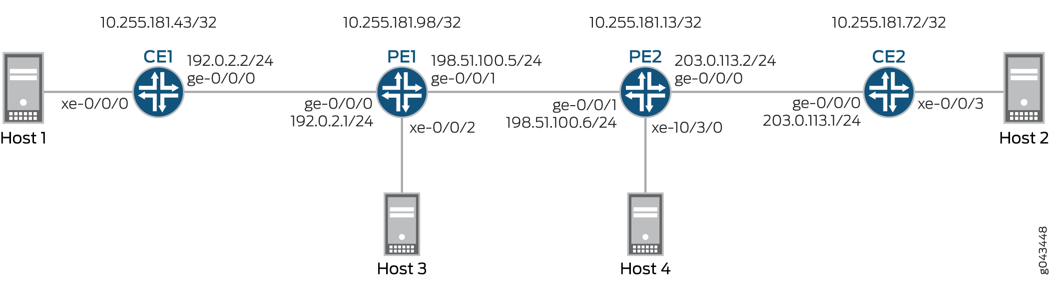
그림 1 은 서로 다른 데이터센터(각각 DC1 및 DC2)에 위치한 디바이스 PE1 및 PE2 간에 EVPN을 사용한 VXLAN 데이터센터 상호 연결을 보여줍니다. 각 PE 디바이스는 하나의 CE 디바이스와 하나의 호스트에 연결됩니다. 모든 PE 및 CE 디바이스는 VLAN 10 아래에 구성되며 동일한 VXLAN 네트워크 식별자(VNI) 10으로 구성됩니다. 디바이스 CE1 및 PE1은 192.168.1.10의 멀티캐스트 그룹에 속하고, 디바이스 CE2 및 PE2는 172.16.1.10의 멀티캐스트 그룹에 속합니다.
토폴로지
구성
CLI 빠른 구성
이 예제를 빠르게 구성하려면 다음 명령을 복사하여 텍스트 파일에 붙여 넣은 다음 줄 바꿈을 제거하고, 네트워크 구성을 일치하는 데 필요한 세부 정보를 변경하고, 명령을 복사하여 계층 수준에서 CLI에 [edit] 붙여 넣은 다음, 구성 모드에서 commit을 입력합니다.
CE1
set interfaces xe-0/0/0 vlan-tagging
set interfaces xe-0/0/0 encapsulation flexible-ethernet-services
set interfaces xe-0/0/0 unit 10 encapsulation vlan-bridge
set interfaces xe-0/0/0 unit 10 vlan-id 10
set interfaces ge-0/0/0 unit 0 family inet address 192.0.2.2/24
set interfaces ge-0/0/0 unit 0 family mpls
set interfaces lo0 unit 0 family inet address 10.255.181.43/32
set protocols ospf area 0.0.0.0 interface ge-0/0/0.0
set protocols ospf area 0.0.0.0 interface lo0.0 passive
set protocols ospf area 0.0.0.0 interface fxp0.0 disable
set protocols pim rp local address 10.255.181.43
set protocols pim interface all
set bridge-domains evpn10 vlan-id 10
set bridge-domains evpn10 interface xe-0/0/0.10
set bridge-domains vxlan vni 10
set bridge-domains vxlan multicast-group 172.16.1.10
set bridge-domains vxlan encapsulate-inner-vlan
set bridge-domains vxlan decapsulate-accept-inner-vlan
CE2
set interfaces xe-0/0/3 vlan-tagging
set interfaces xe-0/0/3 encapsulation flexible-ethernet-services
set interfaces xe-0/0/3 unit 10 encapsulation vlan-bridge
set interfaces xe-0/0/3 unit 10 vlan-id 10
set interfaces lo0 unit 0 family inet address 10.255.181.72/32
set protocols ospf area 0 interface ge-0/0/0.0
set protocols ospf area 0 interface lo0.0 passive
set protocols ospf area 0 interface fxp0.0 disable
set protocols pim rp local address 10.255.181.72
set protocols pim interface all
set bridge-domains evpn10 vlan-id 10
set bridge-domains evpn10 interface xe-0/0/3.10
set bridge-domains vxlan vni 10
set bridge-domains vxlan multicast-group 192.168.1.10
set bridge-domains vxlan encapsulate-inner-vlan
set bridge-domains vxlan decapsulate-accept-inner-vlan
PE1
set interfaces xe-0/0/2 vlan-tagging
set interfaces xe-0/0/2 encapsulation flexible-ethernet-services
set interfaces xe-0/0/2 unit 10 encapsulation vlan-bridge
set interfaces xe-0/0/2 unit 10 vlan-id 10
set interfaces ge-0/0/0 unit 0 family inet address 192.0.2.1/24
set interfaces ge-0/0/1 mtu 1600
set interfaces ge-0/0/1 unit 0 family inet address 198.51.100.5/24
set interfaces ge-0/0/1 unit 0 family mpls
set interfaces lo0 unit 1 family inet address 10.255.181.98/32
set protocols rsvp interface all
set protocols mpls no-cspf
set protocols mpls label-switched-path to-PE2 to 10.255.181.13
set protocols mpls interface all
set protocols bgp family evpn signaling
set protocols bgp group ibgp type internal
set protocols bgp group ibgp neighbor 10.255.181.13 local-address 10.255.181.98
set protocols ospf area 0 interface ge-0/0/1.0
set protocols ospf area 0 interface fxp0.0 disable
set protocols ospf area 0 interface lo0.0 passive
set routing-instances evpn10 vtep-source-interface lo0.0
set routing-instances evpn10 instance-type evpn
set routing-instances evpn10 vlan-id 10
set routing-instances evpn10 interface xe-0/0/2.10
set routing-instances evpn10 vxlan vni 10
set routing-instances evpn10 vxlan multicast-group 172.16.1.10
set routing-instances evpn10 vxlan encapsulate-inner-vlan
set routing-instances evpn10 vxlan decapsulate-accept-inner-vlan
set routing-instances evpn10 route-distinguisher 10.255.181.98:10
set routing-instances evpn10 vrf-target target:10:10
set routing-instances evpn10 protocols evpn
set routing-instances evpna instance-type vrf
set routing-instances evpna route-distinguisher 10.255.181.98:11
set routing-instances evpna vrf-target target:65000:11
set routing-instances evpna vrf-table-label
set routing-instances vrf instance-type vrf
set routing-instances vrf interface ge-0/0/0.0
set routing-instances vrf interface lo0.0
set routing-instances vrf route-distinguisher 10.255.181.98:100
set routing-instances vrf vrf-target target:100:100
set routing-instances vrf protocols ospf area 0 interface lo0.0 passive
set routing-instances vrf protocols ospf area 0 interface ge-0/0/0.0
set routing-instances vrf protocols pim rp static address 10.255.181.43
set routing-instances vrf protocols pim interface all
PE2
set interfaces ge-0/0/1 mtu 1600
set interfaces ge-0/0/1 unit 0 family inet address 198.51.100.6/24
set interfaces ge-0/0/1 unit 0 family mpls
set interfaces xe-10/3/0 vlan-tagging
set interfaces xe-10/3/0 encapsulation flexible-ethernet-services
set interfaces xe-10/3/0 unit 10 encapsulation vlan-bridge
set interfaces xe-10/3/0 unit 10 vlan-id 10
set interfaces lo0 unit 1 family inet address 10.255.181.13/32
set protocols rsvp interface all
set protocols mpls no-cspf
set protocols mpls label-switched-path to-PE1 to 10.255.181.98
set protocols mpls interface all
set protocols bgp family evpn signaling
set protocols bgp group ibgp type internal
set protocols bgp group ibgp neighbor 10.255.181.98 local-address 10.255.181.13
set protocols ospf area 0 interface ge-0/0/1.0
set protocols ospf area 0 interface fxp0.0 disable
set protocols ospf area 0 interface lo0.0 passive
set routing-instances evpn10 vtep-source-interface lo0.0
set routing-instances evpn10 instance-type evpn
set routing-instances evpn10 vlan-id 10
set routing-instances evpn10 interface xe-10/3/0.10
set routing-instances evpn10 vxlan vni 10
set routing-instances evpn10 vxlan multicast-group 192.168.1.10
set routing-instances evpn10 vxlan encapsulate-inner-vlan
set routing-instances evpn10 vxlan decapsulate-accept-inner-vlan
set routing-instances evpn10 route-distinguisher 10.255.181.13:10
set routing-instances evpn10 vrf-target target:10:10
set routing-instances evpn10 protocols evpn
set routing-instances evpna instance-type vrf
set routing-instances evpna route-distinguisher 10.255.181.13:11
set routing-instances evpna vrf-target target:65000:11
set routing-instances evpna vrf-table-label
set routing-instances vrf instance-type vrf
set routing-instances vrf interface xe-10/3/0.0
set routing-instances vrf interface lo0.0
set routing-instances vrf route-distinguisher 10.255.181.13:100
set routing-instances vrf vrf-target target:100:100
set routing-instances vrf protocols ospf area 0 interface lo0.0 passive
set routing-instances vrf protocols ospf area 0 interface xe-10/3/0.0
set routing-instances vrf protocols pim rp static address 10.255.181.72
set routing-instances vrf protocols pim interface all
절차
단계별 절차
다음 예제에서는 구성 계층의 다양한 수준을 탐색해야 합니다. CLI 탐색에 대한 정보는 구성 모드에서 CLI 편집기 사용의 내용을 참조하십시오.
디바이스 CE1 구성:
적절한 인터페이스 이름, 주소 및 기타 매개 변수를 수정한 후 디바이스 CE2에 대해 이 절차를 반복합니다.
디바이스 CE1 인터페이스를 구성합니다.
[edit interfaces]
user@CE1# set xe-0/0/0 vlan-tagging
user@CE1# set xe-0/0/0 encapsulation flexible-ethernet-services
user@CE1# set xe-0/0/0 unit 10 encapsulation vlan-bridge
user@CE1# set xe-0/0/0 unit 10 vlan-id 10
user@CE1# set ge-0/0/0 unit 0 family inet address 192.0.2.2/24
user@CE1# set ge-0/0/0 unit 0 family mpls
user@CE1# set lo0 unit 0 family inet address 10.255.181.43/32
관리 인터페이스를 제외한 디바이스 CE1 인터페이스에서 OSPF를 활성화합니다.
[edit protocols]
user@CE1# set ospf area 0.0.0.0 interface ge-0/0/0.0
user@CE1# set ospf area 0.0.0.0 interface lo0.0 passive
user@CE1# set ospf area 0.0.0.0 interface fxp0.0 disable
디바이스 CE1의 모든 인터페이스에서 PIM을 활성화합니다.
[edit protocols]
user@CE1# set pim rp local address 10.255.181.43
user@CE1# set pim interface all
EVPN 브리지 도메인을 구성하고 VLAN ID 및 인터페이스를 할당합니다.
[edit bridge-domains]
user@CE1# set evpn10 vlan-id 10
user@CE1# set evpn10 interface xe-0/0/0.10
VXLAN 브리지 도메인을 구성하고, VXLAN ID, 멀티캐스트 그룹 주소, 캡슐화 및 캡슐화 해제 매개 변수를 할당합니다.
[edit bridge-domains]
user@CE1# set vxlan vni 10
user@CE1# set vxlan multicast-group 172.16.1.10
user@CE1# set vxlan encapsulate-inner-vlan
user@CE1# set vxlan decapsulate-accept-inner-vlan
단계별 절차
디바이스 PE1 구성:
적절한 인터페이스 이름, 주소 및 기타 매개 변수를 수정한 후 디바이스 PE2에 대해 이 절차를 반복합니다.
디바이스 PE1 인터페이스를 구성합니다.
[edit interfaces]
user@PE1# set xe-0/0/2 vlan-tagging
user@PE1# set xe-0/0/2 encapsulation flexible-ethernet-services
user@PE1# set xe-0/0/2 unit 10 encapsulation vlan-bridge
user@PE1# set xe-0/0/2 unit 10 vlan-id 10
user@PE1# set ge-0/0/0 unit 0 family inet address 192.0.2.1/24
user@PE1# set ge-0/0/1 mtu 1600
user@PE1# set ge-0/0/1 unit 0 family inet address 198.51.100.5/24
user@PE1# set ge-0/0/1 unit 0 family mpls
user@PE1# set lo0 unit 1 family inet address 10.255.181.98/32
디바이스 PE1의 모든 인터페이스에서 MPLS 및 RSVP를 활성화합니다.
[edit protocols]
user@PE1# set rsvp interface all
user@PE1# set mpls no-cspf
user@PE1# set mpls interface all
디바이스 PE1에서 디바이스 PE2로 레이블 스위칭 경로를 구성합니다.
[edit protocols]
user@PE1# set mpls label-switched-path to-PE2 to 10.255.181.13
디바이스 PE1과 PE2 간에 내부 BGP 피어링을 구성하고 BGP 세션에 대한 EVPN 시그널링을 활성화합니다.
[edit protocols]
user@PE1# set bgp family evpn signaling
user@PE1# set bgp group ibgp type internal
user@PE1# set bgp group ibgp neighbor 10.255.181.13 local-address 10.255.181.98
관리 인터페이스를 제외한 디바이스 PE1 인터페이스에서 OSPF를 구성합니다.
[edit protocols]
user@PE1# set ospf area 0 interface ge-0/0/1.0
user@PE1# set ospf area 0 interface fxp0.0 disable
user@PE1# set ospf area 0 interface lo0.0 passive
EVPN 라우팅 인스턴스를 구성하고, VXLAN 터널 엔드포인트 소스 인터페이스, VLAN ID를 할당하고, 경로 구분자 및 VRF 대상 값을 할당하고, 라우팅 인스턴스에 디바이스 PE1 인터페이스를 할당합니다.
[edit routing-instances]
user@PE1# set evpn10 vtep-source-interface lo0.0
user@PE1# set evpn10 instance-type evpn
user@PE1# set evpn10 vlan-id 10
user@PE1# set evpn10 interface xe-0/0/2.10
user@PE1# set evpn10 route-distinguisher 10.255.181.13:10
user@PE1# set evpn10 vrf-target target:10:10
user@PE1# set evpn10 protocols evpn
EVPN 라우팅 인스턴스에 VXLAN ID, 멀티캐스트 그룹 주소, 캡슐화 및 캡슐화 해제 매개 변수를 할당합니다.
[edit routing-instances]
user@PE1# set evpn10 vxlan vni 10
user@PE1# set evpn10 vxlan multicast-group 172.16.1.10
user@PE1# set evpn10 vxlan encapsulate-inner-vlan
user@PE1# set evpn10 vxlan decapsulate-accept-inner-vlan
첫 번째 VPN 라우팅 및 포워딩(VRF) 라우팅 인스턴스를 구성하고 경로 구분자 및 vrf-target 값을 할당합니다.
[edit routing-instances]
user@PE1# set evpna instance-type vrf
user@PE1# set evpna route-distinguisher 10.255.181.13:11
user@PE1# set evpna vrf-target target:65000:11
user@PE1# set evpna vrf-table-label
두 번째 VRF 라우팅 인스턴스를 구성하고 디바이스 PE1 인터페이스, 경로 구분자 및 vrf-target 값을 할당합니다.
[edit routing-instances]
user@PE1# set vrf instance-type vrf
user@PE1# set vrf interface ge-0/0/0.0
user@PE1# set vrf interface lo0.0
user@PE1# set vrf route-distinguisher 10.255.181.13:100
user@PE1# set vrf vrf-target target:100:100
두 번째 VRF 라우팅 인스턴스에 대한 OSPF 및 PIM 프로토콜을 구성합니다.
[edit routing-instances]
user@PE1# set vrf protocols ospf area 0 interface lo0.0 passive
user@PE1# set vrf protocols ospf area 0 interface ge-0/0/0.0
user@PE1# set vrf protocols pim rp static address 10.255.181.43
user@PE1# set vrf protocols pim interface all
결과
구성 모드에서 , show protocols및 show routing-instances 명령을 입력하여 show interfaces구성을 확인합니다. 출력에 의도한 구성이 표시되지 않으면 이 예의 지침을 반복하여 구성을 수정하십시오.
CE1
user@CE1# show interfaces
xe-0/0/0 {
    vlan-tagging;
    encapsulation flexible-ethernet-services;
    unit 10 {
        encapsulation vlan-bridge;
        vlan-id 10;
    }
}
ge-0/0/0 {
    unit 0 {
        family inet {
            address 192.0.2.2/24;
        }
        family mpls;
    }
}
lo0 {
    unit 0 {
        family inet {
            address 10.255.181.43/32;
        }
    }
}
user@CE1# show protocols
ospf {
    area 0.0.0.0 {
        interface ge-0/0/0.0;
        interface lo0.0 {
            passive;
        }
        interface fxp0.0 {
            disable;
        }
    }
}
pim {
    rp {
        local {
            address 10.255.181.43;
        }
    }
    interface all;
}
user@CE1# show bridge-domains
evpn10 {
    vlan-id 10;
    interface xe-0/0/0.10;
    vxlan {
        vni 10;
        multicast-group 172.16.1.10;
        encapsulate-inner-vlan;
        decapsulate-accept-inner-vlan;
    }
}
PE1
user@PE1# show interfaces
xe-0/0/2 {
    vlan-tagging;
    encapsulation flexible-ethernet-services;
    unit 10 {
        encapsulation vlan-bridge;
        vlan-id 10;
    }
}
ge-0/0/0 {
    unit 0 {
        family inet {
            address 192.0.2.1/24;
        }
    }
}
ge-0/0/1 {
    mtu 1600;
    unit 0 {
        family inet {
            address 198.51.100.5/24;
        }
        family mpls;
    }
}
lo0 {
    unit 1 {
        family inet {
            address 10.255.181.98/32;
        }
    }
}
user@PE1# show protocols
rsvp {
    interface all;
}
mpls {
    no-cspf;
    label-switched-path to-PE2 {
        to 10.255.181.13;
    }
    interface all;
}
bgp {
    family evpn {
        signaling;
    }
    group ibgp {
        type internal;
        neighbor 10.255.181.13 {
            local-address 10.255.181.98;
        }
    }
}
ospf {
    area 0.0.0.0 {
        interface ge-0/0/1.0;
        interface fxp0.0 {
            disable;
        }
        interface lo0.0 {
            passive;
        }
    }
}
user@PE1# show routing-instances
evpn10 {
    vtep-source-interface lo0.0;
    instance-type evpn;
    vlan-id 10;
    interface xe-0/0/2.10;
    vxlan {
        vni 10;
        multicast-group 172.16.1.10;
        encapsulate-inner-vlan;
        decapsulate-accept-inner-vlan;
    }
    route-distinguisher 10.255.181.13:10;
    vrf-target target:10:10;
    protocols {
        evpn;
    }
}
evpna {
    instance-type vrf;
    route-distinguisher 10.255.181.98:11;
    vrf-target target:65000:11;
    vrf-table-label;
}
vrf {
    instance-type vrf;
    interface ge-0/0/0.0;
    interface lo0.0;
    route-distinguisher 10.255.181.98:100;
    vrf-target target:100:100;
    protocols {
        ospf {
            area 0.0.0.0 {
                interface lo0.0 {
                    passive;
                }
                interface ge-0/0/0.0;
            }
        }
        pim {
            rp {
                static {
                    address 10.255.181.43;
                }
            }
            interface all;
        }
    }
}
확인
구성이 올바르게 작동하고 있는지 확인합니다.
MAC 학습 확인
목적
CE 및 PE 디바이스에서 브리징 및 EVPN MAC 테이블 항목을 확인합니다.
작업
디바이스 CE1에서 브리징 MAC 테이블 항목을 결정합니다.
운영 모드에서 명령을 실행합니다 show bridge mac-table .
user@CE1> show bridge mac-table

 MAC flags       (S -static MAC, D -dynamic MAC, L -locally learned, C -Control MAC
     O -OVSDB MAC, SE -Statistics enabled, NM -Non configured MAC, R -Remote PE MAC)

 Routing instance : default-switch
  Bridging domain : evpn10, VLAN : 10
    MAC                 MAC      Logical          NH     RTR
    address             flags    interface        Index  ID
    00:00:00:00:00:11   D        xe-0/0/0.10
    00:00:00:00:00:22   D        vtep.32769
디바이스 PE1에서 EVPN MAC 테이블 항목을 결정합니다.
운영 모드에서 명령을 실행합니다 show evpn mac-table .
user@PE1> show evpn mac-table

 MAC flags       (S -static MAC, D -dynamic MAC, L -locally learned, C -Control MAC
     O -OVSDB MAC, SE -Statistics enabled, NM -Non configured MAC, R -Remote PE MAC)

 Routing instance : evpn10
  Bridging domain : __evpn10__, VLAN : 10
    MAC                 MAC      Logical          NH     RTR
    address             flags    interface        Index  ID
    00:00:00:00:00:11   D        vtep.32769
    00:00:00:00:00:22   DC                        1048576 1048576
의미
브리징 및 EVPN MAC 테이블은 VLAN 구성을 학습했습니다.
PIM 연결성 확인
목적
PIM 구성이 CE 및 PE 디바이스에서 제대로 작동하는지 확인합니다.
작업
디바이스 CE1에서 PIM 구성을 확인합니다.
운영 모드에서 명령을 실행합니다 show pim rps extensive .
user@CE1> show pim rps extensive
 Instance: PIM.master

 address-family INET

 RP: 10.255.181.43
 Learned via: static configuration
 Mode: Sparse
 Time Active: 00:06:08
 Holdtime: 150
 Device Index: 161
 Subunit: 32769
 Interface: pd-0/2/0.32769
 Static RP Override: Off
 Group Ranges:
         224.0.0.0/4
 Register State for RP:
 Group           Source          FirstHop        RP Address      State    Timeout
 172.16.1.10      203.1.113.11       203.1.113.11       10.255.181.43   Receive      171

 address-family INET6
운영 모드에서 명령을 실행합니다 show pim join extensive .
user@CE1> show pim join extensive
 Instance: PIM.master Family: INET
 R = Rendezvous Point Tree, S = Sparse, W = Wildcard

 Group: 172.16.1.10
     Source: *
     RP: 10.255.181.43
     Flags: sparse,rptree,wildcard
     Upstream interface: Local
     Upstream neighbor: Local
     Upstream state: Local RP
     Uptime: 00:06:08
     Downstream neighbors:
         Interface: ge-0/0/0.0 (assert winner)
             192.0.2.1 State: Join Flags: SRW Timeout: 201
             Uptime: 00:05:08 Time since last Join: 00:00:08
             Assert Winner: 192.0.2.2 Metric: 0 Pref: 2147483648 Timeout: 82
         Interface: Pseudo-VXLAN
     Number of downstream interfaces: 2

 Group: 172.16.1.10
     Source: 10.255.181.43
     Flags: sparse,spt
     Upstream interface: Local
     Upstream neighbor: Local
     Upstream state: Local Source, Local RP, No Prune to RP
     Keepalive timeout: 338
     Uptime: 00:04:15
     Downstream neighbors:
         Interface: ge-0/0/0.0
             192.0.2.1 State: Join Flags: S Timeout: 201
             Uptime: 00:04:15 Time since last Join: 00:00:08
         Interface: Pseudo-VXLAN
     Number of downstream interfaces: 2

 Group: 172.16.1.10
     Source: 203.1.113.11
     Flags: sparse,spt
     Upstream interface: ge-0/0/0.0
     Upstream neighbor: 192.0.2.1 (assert winner)
     Upstream state: Local RP, Join to Source, No Prune to RP
     Keepalive timeout: 338
     Uptime: 00:04:15
     Downstream neighbors:
         Interface: ge-0/0/0.0 (pruned)
             192.0.2.1 State: Prune Flags: SR Timeout: 201
             Uptime: 00:04:15 Time since last Prune: 00:00:08
             Assert Winner: 192.0.2.1 Metric: 0 Pref: 0 Timeout: 179
         Interface: Pseudo-VXLAN
     Number of downstream interfaces: 2

 Instance: PIM.master Family: INET6
 R = Rendezvous Point Tree, S = Sparse, W = Wildcard
의미
PIM을 사용하는 디바이스 연결성은 구성된 대로 작동합니다.
VXLAN 연결성 확인
목적
서로 다른 데이터센터에 있는 VTEP 간의 연결을 확인합니다.
작업
운영 모드에서 , show l2-learning vxlan-tunnel-end-point remote, 및 show interfaces vtep 명령을 실행합니다show l2-learning vxlan-tunnel-end-point source.
user@PE1> show l2-learning vxlan-tunnel-end-point source
 Logical System Name       Id  SVTEP-IP         IFL   L3-Idx
        <default>                 0   203.1.113.11        lo0.0    7
     L2-RTT                   Bridge Domain              VNID     MC-Group-IP

     evpn10                   __evpn10__                 10       172.16.1.10
user@PE2> show l2-learning vxlan-tunnel-end-point source
 Logical System Name       Id  SVTEP-IP         IFL   L3-Idx
        <default>                 0   203.1.113.12        lo0.0    7
     L2-RTT                   Bridge Domain              VNID     MC-Group-IP
     evpn10                   __evpn10__                 10       192.168.1.10
user@PE1> show l2-learning vxlan-tunnel-end-point remote
 Logical System Name       Id  SVTEP-IP         IFL   L3-Idx
        <default>                 0   203.1.113.11        lo0.0    7
  RVTEP-IP         IFL-Idx   NH-Id
  10.255.181.43    2684275660 2684275660
     VNID          MC-Group-IP
     10            172.16.1.10
user@PE2> show l2-learning vxlan-tunnel-end-point remote
 Logical System Name       Id  SVTEP-IP         IFL   L3-Idx
        <default>                 0   203.1.113.12        lo0.0    7
  RVTEP-IP         IFL-Idx   NH-Id
  10.255.181.98    351       661
     VNID          MC-Group-IP
     10            192.168.1.10
user@PE1> show interfaces vtep
 Physical interface: vtep, Enabled, Physical link is Up
   Interface index: 133, SNMP ifIndex: 508
   Type: Software-Pseudo, Link-level type: VxLAN-Tunnel-Endpoint, MTU: 1600, Speed: Unlimited
   Device flags   : Present Running
   Interface flags: SNMP-Traps
   Link type      : Full-Duplex
   Link flags     : None
   Last flapped   : Never
     Input packets : 0
     Output packets: 0

   Logical interface vtep.32768 (Index 339) (SNMP ifIndex 560)
     Flags: Up SNMP-Traps Encapsulation: ENET2
     Ethernet segment value: 00:00:00:00:00:00:00:00:00:00, Mode: Single-homed, Multi-homed status: Forwarding
     VXLAN Endpoint Type: Source, VXLAN Endpoint Address: 203.1.113.11, L2 Routing Instance: evpn10, L3 Routing Instance: vrf
     Input packets : 0
     Output packets: 0

   Logical interface vtep.32769 (Index 341) (SNMP ifIndex 567)
     Flags: Up SNMP-Traps Encapsulation: ENET2
     VXLAN Endpoint Type: Remote, VXLAN Endpoint Address: 10.255.181.43, L2 Routing Instance: evpn10, L3 Routing Instance: vrf
     Input packets : 143746
     Output packets: 95828
     Protocol bridge, MTU: 1600
       Flags: Trunk-Mode
의미
출력은 VXLAN에 대한 올바른 터널 소스 IP 주소(루프백 인터페이스에 할당됨), VLAN 및 멀티캐스트 그룹을 보여줍니다. 디바이스 PE1은 IP 주소(루프백 인터페이스에 할당된 주소)가 출력에 나타나기 때문에 연결할 수 있습니다. 또한 출력은 VXLAN(VNI 10) 및 해당 멀티캐스트 그룹이 원격 VTEP, 디바이스 PE2에서 올바르게 구성되었음을 보여줍니다.