従来のエンタープライズネットワークをジュニパーのキャンパスファブリックに移行
この情報(ビデオ、図、概要ワークフローなど)を使用して、キャンパスファブリックアーキテクチャへの移行について学習します。
このドキュメントでは、従来のエンタープライズネットワークベースのアーキテクチャをジュニパーキャンパスファブリックEVPN-VXLANアーキテクチャに移行するために使用できる戦略について詳しく説明します。
ジュニパーのキャンパスファブリックでは、EVPN VXLANを中小規模の企業導入の基盤技術として活用しています。MistのWired Assuranceクラウド対応フレームワークを使用して、キャンパスファブリックを構築して管理できます。ジュニパーのキャンパスファブリックの詳細については 、Wired Assurance Juniper Mistデータシートをご覧ください。
At the MIST user interface, we are looking at the various switches that will be part of the Campus Fabric build. As we mentioned earlier, we've got a couple of access switches, a couple of core switches, a couple of distribution switches, their current version of code, the model of switch, of course, and other information that we can add. We can actually add all kinds of information to this particular setup through just a real easy drop-down menu here.
One thing I want to mention is that although these devices are connected, they don't have to be connected to build the fabric. So they do have to be part of the organizational unit, so they have to be claimed or adopted into the org unit, and that's a MIST process. Once they are claimed or adopted, then we can build the fabric irrespective of whether they're connected or not.
So let's go look at access points. We've got an access point connected to access one, and that is currently disconnected, which makes a lot of sense because that switch is in idle mode right now waiting for the network to be built. So let's go jump into the build.
So we hit the organizational option and Campus Fabric. Okay, so a couple of items here. We've been able to build a Campus Fabric at a site level since the inception of Wired Insurance, but what we're going to do is we're going to focus at the organizational level because this aligns with some of the larger enterprises, large universities, healthcare systems where they want to have a multi-pod approach, and they want to connect those pods through a core layer, if you will, and then that core layer offshoots to the internet, or maybe you build a services block on top of that core layer for external connectivity requirements.
So let's start with the Campus Fabric build here. So since we talked about and we are going to demonstrate group-based policy, this requires the Campus Fabric IP Clos type of architecture, which means that we're extending VXLAN down to the access layer, and we talked about that VXLAN header earlier. That's where the scalable group tag, the 16-bit header for GBP is associated.
We're going to push the layer 3 edge all the way down to the access layer. We can put it at access layer, at distribution. It doesn't matter for GBP.
Either one works fine, and then we've got a topology settings here that are relatively straightforward. We use EBGP for underlay and overlay. We support equal cost multipath for underlay and overlay, and so this setting right here is relatively straightforward.
Customers don't really change the topology settings at all. We don't recommend they change them, but if they want to, they can, so it's certainly customizable, and then the subnet clarification here is these are the point-to-point subnets between the adjacent layers, so access layer to distribution, distribution to core, and those are the particular subnet addresses. All right.
Next option is to select the devices that we are going to add to our complete Campus Fabric build, so we're going to start with the core. You'll notice the core is a more option, so for mid-tier, smaller deployments, I would expect this would be used, and this would be where the customer is okay with terminating the outside world directly to the core, so they might have a firewall cluster, maybe a couple of routers that they pull directly into the core, and that's a clean approach for them. The cores of order option just provides the VXLAN awareness, the encapsulation, de-encapsulation of VXLAN to VLAN, and so forth at the core.
However, customers that might be a little bit larger or that want to keep a lean core where the core is just a very high-speed router, pack it in, pack it out as fast as possible, they can deselect this option and actually build a single or a pair, which is recommended of switches, to handle that border node piece, that border gateway piece, and that would be where a customer would, once again, connect the internet, their WAN edge devices, their firewalls, maybe critical infrastructure, DHB radio servers, those devices that really they want to offshoot into their own pod, if you will, but we're going to go ahead and keep this selected here for the sake of our demo. We're going to name the pod Santa Clara Hilton because that's where we are located, and then we'll add both 5120 distribution switches, and we were going to add one access switch, which is access one. We'll come back later and add access two.
Real simple stuff here, right? So we click on connect, continue, and then this is really where MIST begins to provide quite a bit of value. So we have a pre-configured template that we add or import into the fabric, so our VLANs are created with our IP addresses. This would be the address default gateway pushed down to the access layer.
When I add access two, it's actually going to use the same addressing scheme, so same VLAN, same IP addressing. We're using Anycast in this particular deployment model. Real easy to configure, single IP address, single MAC entry.
Once again, all hidden using the MIST UI. Customers, once they see the simplicity of how they build VRFs, they go ahead and just knock themselves out with that. So we're going to build a guest Wi-Fi and a Corp IT VRF.
Both desktops are going to be placed into Corp IT as they were part of, kind of, if you want to consider that the same routing, it's the same VRF, same administrative domain. These are devices that can communicate amongst themselves without having to traverse through a third-party device like a router or a firewall. So we'll build that there, and then we're going to build guest Wi-Fi, and we're going to add that particular VLAN, which is where that AP, remember the AP is disconnected, the one that showed earlier, that's off that particular broadcast domain.
So, real simple, I mean, we added or we imported a template which had pre-configured layer two, layer three, that was automatically assigned to the access layer at, because that's what we're doing, our layer three boundary for default gateway capabilities, and then we added a couple VRFs with the proper networks. Last bit of information is where we actually interconnect the layers. So the core is going to communicate with both distribution switches only, and we do that here.
And so core one and core two connect to distribution one and two, and we see here that we've got five and six ports for both disk one and disk two. Now, as we build this out, the fabric itself is using LDP from a telemetry perspective to validate that the endpoint devices that we are communicating with, once these ports go live, that the name matches what we expect it to see on the other end, right, on the config. So if I happen to misconfigure and select the wrong ports, then this system will absolutely tell me, and I can easily go back in and make that change.
So let's go here and let's just select the proper ports that we expect that will be the case here, six and five off disk two, and then we've got, we want to connect to our downstream access switch, and that'll be done here on port 37. And then we go to disk one, we do the same thing, so we're going to connect to five and four for core one and core two. And what's really cool about this is once we're done with the build, we then will be able to download a connection table, and the connection table could be handed to the folks that are actually plugging the devices in if there is a separate group of engineers or maybe other resources that, you know, maybe this is being shipped to another site.
Remember, we can build this without the devices being online, they just have to be onboarded to the org. So we've got this built, now I can click on connect, continue, apply my changes, and we should see this get pushed down relatively quickly. So I'm going to jump really quickly into this, and I want to go down to my access layer first, device, and what I want to do is poke around a little bit.
You notice I can access device through remote show, which is pretty cool. So I like that, I'm just the guy who likes to be able to, you know, poke around and make sure CLI is, because that's my, what I believe is truly the case, CLI is always going to tell the truth. So we've got our BGP session set up right here, that looks good.
So I've got BGP underlay and overlay. Let's go and take a look at my Ethernet switching table, and what we have here is we've got our AP device right there, you see that local. So I'm going to come up here to my desktops, and what I'm going to do is I'm going to start to ping my local device for desktop one, which is 1099, or my local gateway 1099.1. So I'm able to ping that, that's pretty cool.
Come over here and hit this again, I see the local desktop show up. Now I shouldn't see anything across the network, and I really don't. I see the other devices I've got the excellent tunnels to, but remember, we have not yet onboarded Access Switch 2. So here, 1088.1 is my local gateway of desktop 2, and let's take a look at my configuration of desktop 2, and that is here.
So I'm not able to ping that device, and it shouldn't be, but I'm going to keep that ping going, because we're going to add the switch in just a second here. All right, so I'm able to ping there, and I've got internet connectivity from the desktop through the cloud, and the reason I know it's through the cloud is because I could do a trace route, and I could see that my next hop is 1099.1, which is Access 1. That's a good thing. So I'm actually going all the way through the firewall at the top end part of my network to access the internet.
So that was a relatively quick turnaround with respect to BGP and signaling, and actually pushing the configuration down to the devices. That happens within seconds. Now, what takes a little bit longer is just the telemetry piece of what you see here, the actual Campus Fabric EVPN Insights option, which is going to turn green once everything gets collaborated and corresponded back to the cloud.
All right, let's look at the access point. That might not yet be, oh, there it is. It's connected.
Cool. So the access point has connectivity out to the internet through the local Access 1 switch. That's a good thing.
So we've got users that can onboard. We're in pretty good shape there. Let's go back to Campus Fabric, click on this guy, and look around, and what we're going to do is we're going to edit Campus Fabric, and we're going to build, and we're just going to add the secondary switch to this particular configuration, which is Access 2, all right? All we need to do here is we've already built the Layer 3. We've already imported that, so all I need is to go down to my port values and make sure I click on, once again, the right port connecting to Access 2. Relatively straightforward.
LODP is going to help me with this, which is awesome because I make quite a few mistakes. So anyways, we'll go over here, and we'll connect to what we expect to be the proper ports. All right, and let's go ahead and click on Continue, Apply Changes, and Confirm that.
All right, so now we've confirmed that. I'm going to go back to my secure CRT, and I'm going to set up a ping to 10.8.8.8.8.8, and that'll hopefully resolve soon. Okay, we're already pinging our local gateway from the desktop perspective, and that ping across the network should happen pretty quickly as BGP converges.
Wow, that's pretty good timing, man. I couldn't have chosen any better timing there. So we're good there.
That device is operational, and let's go ahead and take a look at Access 2 here just to take, once again, we can remote shell into the device. I actually like to use secure CRT as well, and so you can have an off-board or third-party secure CRT or third-party SSH access application. It doesn't matter, whatever you're most comfortable with, but there is a remote shell capability built into this.
Once again, we're going to look at the Ethernet switching table. We see our local AP. We see dot12, which is the workstation, and if I look at ARP, which helps me a little bit easier, I can see 10.8.8.8.8, and that's a good thing, right? So I'm able to see my local APs, and things look like they're operating as I would expect them to operate.
Let's go back to Desktop 1 here and ping back through to 10.8.8.8, and we're good there. We're hitting that 10.9.9, 9.9, 9.9, good shape there. Okay, so I want to go back to, let's go ahead and minimize this.
We'll go back to our AP. Yeah, we're good there. I'm going to go ahead and refresh my screen up top here, and I would expect that our fabric should be just about built with all devices operational.
Okay, we're in pretty good shape there. Core 1, Core 2, and I'm happy with that. So what we've demonstrated is the Campus Fabric EVPN VXLAN build through the MIS Cloud.
We built the five-stage CLOS that we saw earlier, which is access layer, distribution layer, core layer, attached to a SRX firewall that was pre-built. So that firewall was already built. We had a port profile configured for BGP.
All we need to do is just build the fabric through the template access. So we imported a template for layer 2, layer 3. We applied that against the port values that we selected at the very end, and then here we've got our device, our network, which is operational. And you can see that what's of interest is that these EVPN insights will give us a sense of which of these links are being used heavier than others.
Here we're doing a pretty good job of load balancing. Here we're using one link more than the other. It's just the way that ECMP works on occasion, and we've got some information over here that is applicable as well.
So this has been, once again, the demonstration of Campus Fabric Build. Hopefully this has been good for you guys, and I hope you have a great day. Thank you.
この移行戦略では、従来のアクセス、ディストリビューション、コアの3段階アーキテクチャで構成されるエンタープライズネットワークに焦点を当てています。この例では、core は、すべてのユーザー、プリンター、アクセスポイント (AP) などにレイヤー 3 接続を提供します。また、コア層は、スタンダードベースのOSPFまたはBGP技術を使用して、デュアルWANルーターと相互接続します。
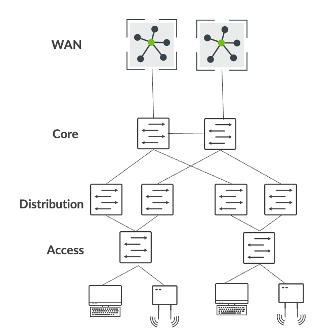
大まかに言うと、従来のエンタープライズネットワークからジュニパーのキャンパスファブリックアーキテクチャへの移行には、次の手順が含まれます。
- 既存のエンタープライズネットワークと並行して、キャンパスファブリックアーキテクチャを構築します。
- サービスブロックを使用して、キャンパスファブリックを既存のネットワークに相互接続します。
- キャンパスファブリックにVLANを1つずつ移行します。
- DHCPサーバーやRADIUSなどの重要なインフラストラクチャをサービスブロックに移行します。
- WANルーターをサービスブロックに移行します。
- すべての接続が確認されたら、既存のエンタープライズネットワークを停止します。
既存ネットワークと並行してキャンパスファブリックを構築
最初のステップとして、MistのWired Assuranceフレームワークを使用してキャンパスファブリックを構築します。このステップにより、既存のネットワークと並行して運用中のキャンパスファブリックを展開することができます。この例では、お客様がアクセスレイヤーにマイクロセグメンテーション戦略を導入しているため、キャンパスファブリックのIP Closアーキテクチャを選択しています。お客様は、キャンパスファブリックのIP Closアーキテクチャに導入するジュニパーの以下の機器を選択しています:
- QFX5120スイッチ(コア層)
- QFX5120スイッチ(ディストリビューション層)
- バーチャルシャーシモード(アクセスレイヤー)のEX4100およびEX4400スイッチ
- QFX5120スイッチ(サービスブロック)
「 キャンパスファブリックのIP Closの設定」も参照してください。
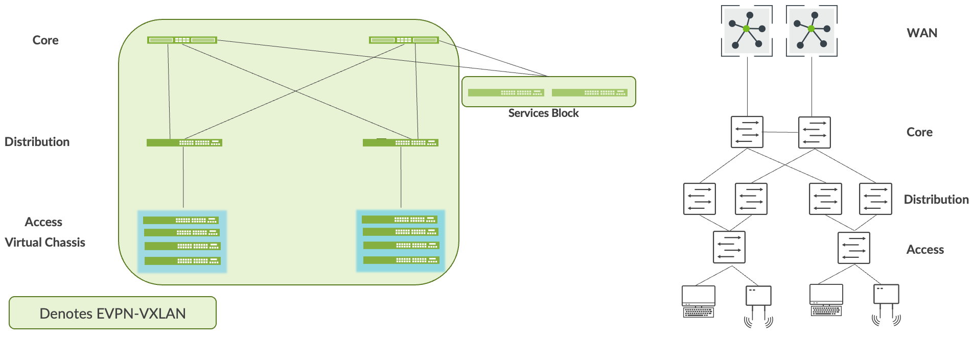 の共存
の共存
キャンパスファブリックを既存ネットワークに相互接続する
サービスブロックを使用して、キャンパスファブリックをエンタープライズネットワークと相互接続できます。そのためには、レイヤー2でESI-LAGテクノロジーを使用するか、レイヤー3接続が必要な場合はBGPやOSPFなどの標準ルーティングプロトコルを使用します。この場合、OSPF を使用してサービス ブロックをコア エンタープライズに相互接続します。
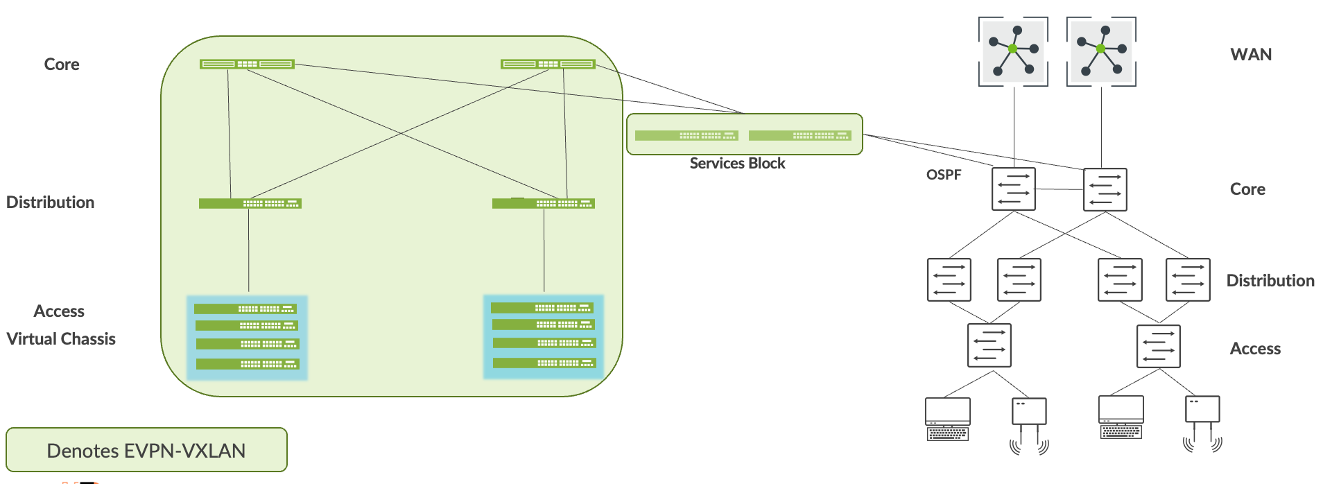 を使用したサービス ブロックとコアの相互接続
2 つのネットワーク間のループバック到達可能性は、サービス ブロックを介して確立する必要があります。たとえば、キャンパスファブリックビルドでは、各デバイスにループバックアドレスを割り当てます。デフォルトでは、これらのアドレスは同じサブネットの一部です。OSPF は、これらのアドレスを、コア層がサービス ブロックを通じて送信したルーティング可能なプレフィックスと交換する必要があります。エンドユーザーは、次のステップに進む前に、これらのプレフィックス間の到達可能性を確認する必要があります。
キャンパスファブリックへのVLANの移行
このプロセスでは、各 VLAN および関連するレイヤー 3 インターフェイスをエンタープライズ ネットワークから削除する必要があります。VLAN内のすべてのデバイスをキャンパスファブリックに移行してから、移行したVLAN上のデバイスからエンタープライズネットワーク上のアプリケーションおよびデバイスへの完全な接続をエンドユーザーに確認してもらう必要があります。次に、この手順の概要を示します。
- 現在のネットワークからレイヤー3サブネットを無効にするか削除することで、VLANをキャンパスファブリックに移行します。
- ユーザーとデバイスは、キャンパスファブリックのアクセスレイヤーに移行します。
- レイヤー 3 相互接続により、VLAN ごとに到達可能性を確保できます。
- ユーザーとデバイスは、次のVLANに移動する前に、すべてのアプリケーションの到達可能性を検証する必要があります。
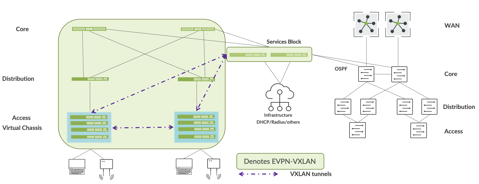 に移行されたすべてのVLANとアクセスデバイス
重要インフラをサービスブロックに移行
ジュニパーでは、各重要なインフラサービス(DHCPサーバーやRADIUSなど)をサービスブロックにデュアルホーミングすることを推奨しています。そのためには、レイヤー2でESI-LAGテクノロジーを使用するか、レイヤー3接続が必要な場合はBGPやOSPFなどの標準ルーティングプロトコルを使用します。次のステップに進む前に、キャンパスファブリック内およびエンタープライズネットワークからの重要なインフラストラクチャサービスへのアクセス性を検証する必要があります。
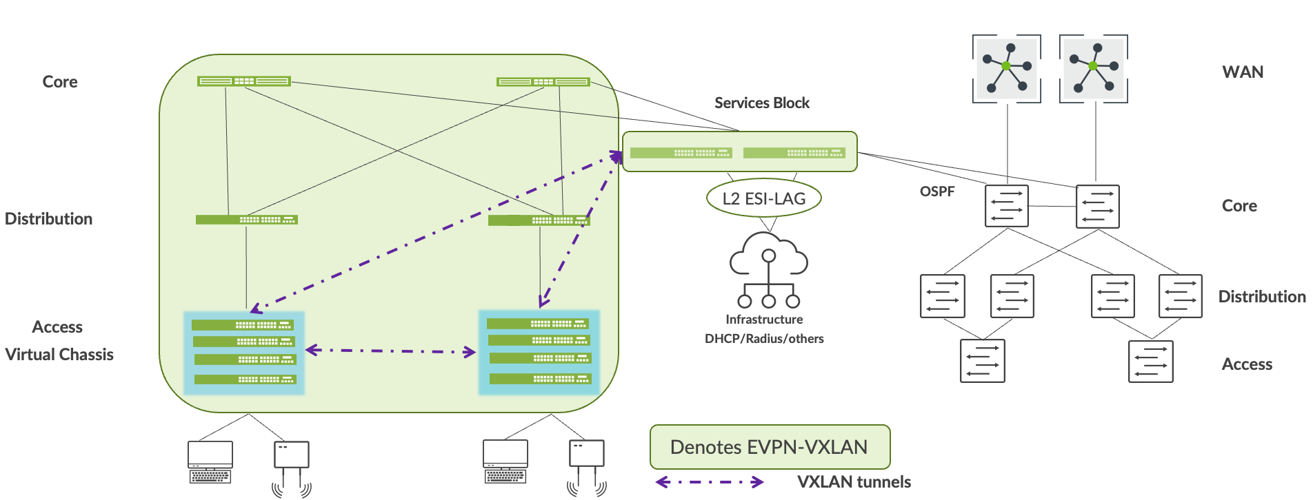 への重要なインフラの移行
WANルーターをサービスブロックに移行する
Mistでは、BGPまたはOSFPを使用してWANルーターをサービスブロックに接続できます。WANルーターをサービスブロックに接続したら、次のステップに進む前に、キャンパスファブリックとの間のWANサービスのアクセシビリティを確認します。
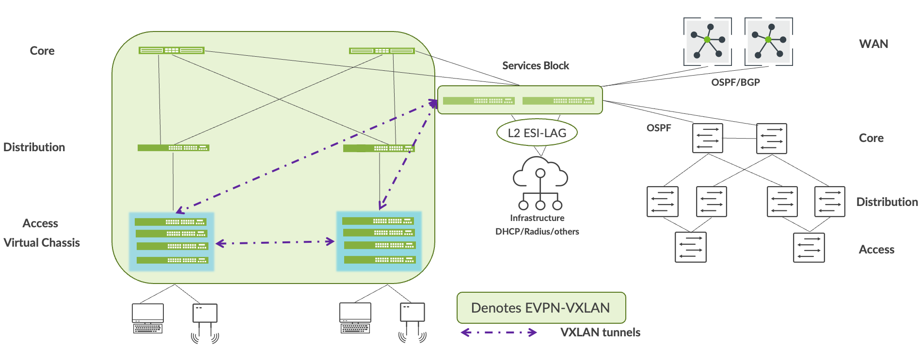 への移行
への移行
既存のエンタープライズネットワークの廃止
すべてのサービスとアプリケーションにキャンパスファブリックとの間で問題なくアクセスできる状態になってから少なくとも1週間は、エンタープライズネットワークを稼働させ、運用状態を維持することを推奨します。その後、既存のエンタープライズネットワークを廃止します。
