
付録:テストケース例情報
仮想テストラボ
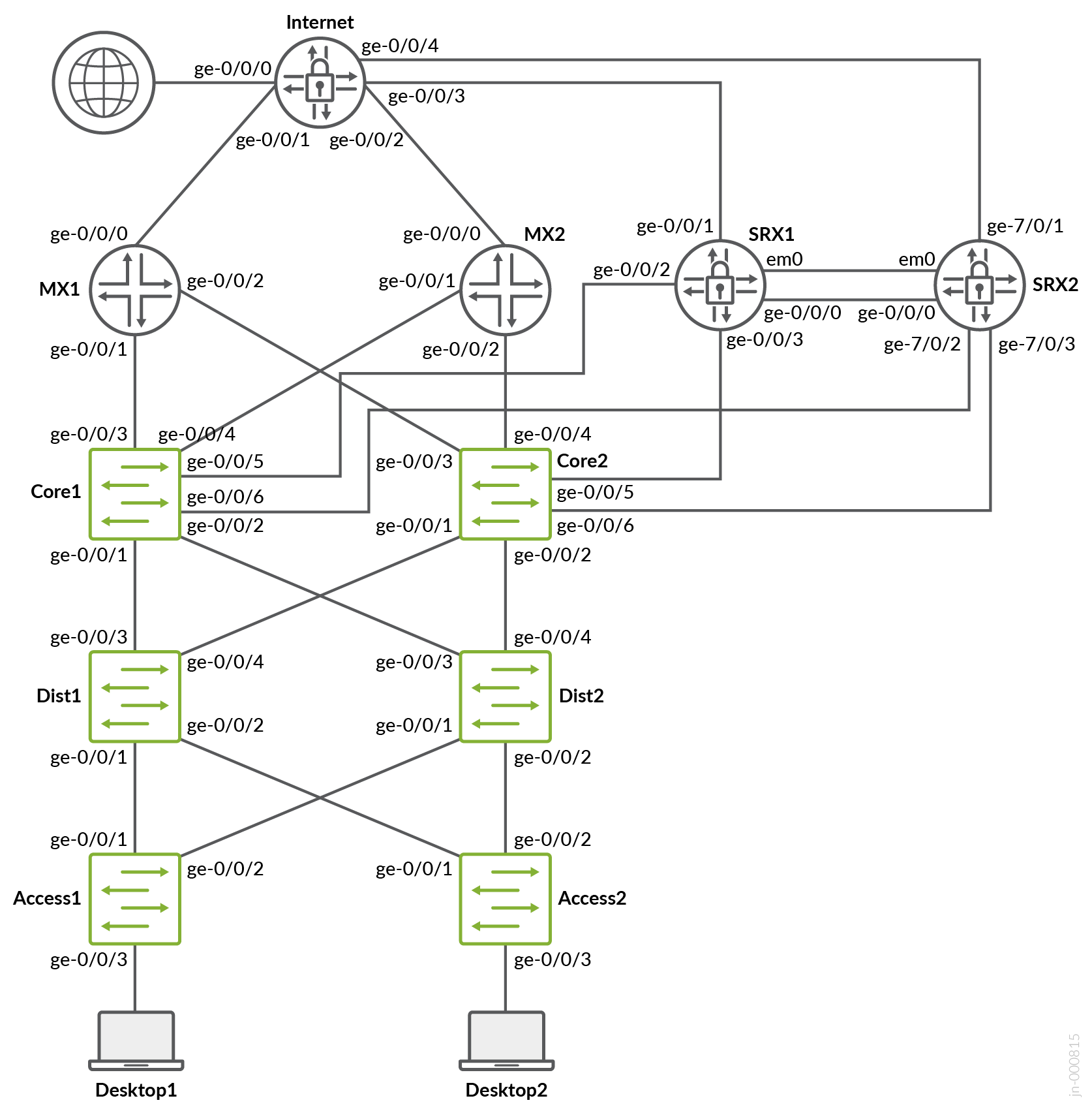
JVDEのこの付録の例は、vJunosスイッチ、vMXルーター、vSRX V3.0ファイアウォールで構成される仮想テストラボで評価されています。仮想サービスブロックスイッチのペアは作成しませんでしたが、両方のタイプのWANルーター(ルーターまたはファイアウォール)を冗長ペアとして使用できるようにしました。これは、物理的なハードウェアを使用する必要のあるテストに使用されたラボとは異なります。これを例として使用し、EVE-NGなどの環境で自分で構築できるものを使用して、構成例をテストするための独自のラボを構築することができます。この場合、ファブリックはIP Closとして設定されていました。
L2 Exit with Stretched VLAN
このJVD-Eの以前のバージョンには、拡張VLANを使用したL2出口の設定例が含まれていました。しかし、これは重大な問題を引き起こし、ユーザーが本番環境での使用を意図していないという事実を見落とすことがよくありました。これ以上の混乱を避けるため、この例を完全に削除することにしました。古いドキュメントにはまだ記載されているかもしれませんが、サポートされていない非実稼働グレードのソリューションであることに変わりはありません。
トランスポートVLANを使用したL2出口
キャンパスファブリックでVLANまたはVRFを作成する場合は、次のベストプラクティスに留意してください。スイッチテンプレートにすべてのVLANを作成し、 キャンパスファブリック ダイアログにインポートします。Mist GUIの他の場所にVLANを作成すると、最終的に一貫性が失われ、問題の解決が困難になります。サービスブロック機能を除き、 キャンパスファブリック ダイアログの外部にVRFを作成しないでください。トランスポートVLAN方式では、サービスブロック機能で手動でVRFを作成し、トランスポートVLANとルートをVRFにローカルに追加する必要があります。 キャンパスファブリック ダイアログでVRFやルートを作成しないでください。スイッチテンプレート内にポートプロファイルを作成し、変更がファブリック内のすべてのスイッチで同期されるようにすることをお勧めします。
スイッチテンプレートでトランスポートVLANを定義する場合、サブネット情報は設定しないでください。この情報は、後で各サービスブロック機能の追加IPサブネットとして設定します。 図1、 図2、および図3を参照してください。
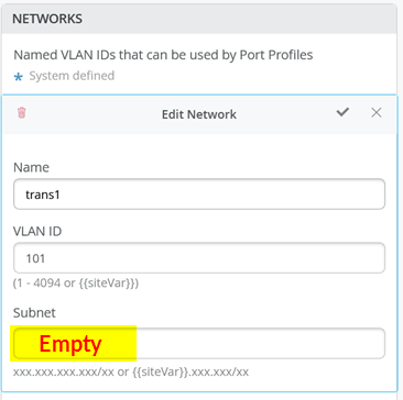 の空のサブネット設定
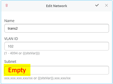 の空のサブネット設定
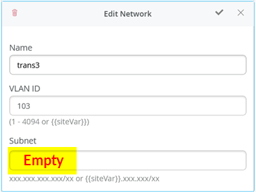 の空のサブネット設定
以下のCLI設定は、トランスポートVLANファブリックで使用されるスイッチテンプレートのエクスポートされたバージョンを示しています。これにより、インポート時に設定を確認できます。ご覧のとおり、VRFごとに最低2つのVLANと、VRFごとに追加のトランスポートVLANがあります。
{
  “additional_config_cmds”: [],
  “networks”: {
    “vlan1099”: {
      “vlan_id”: 1099,
      “subnet”: “10.99.99.0/24”
    },
    “vlan1088”: {
      “vlan_id”: 1088,
      “subnet”: “10.88.88.0/24”
    },
    “vlan1033”: {
      “vlan_id”: 1033,
      “subnet”: “10.33.33.0/24”
    },
    “vlan1091”: {
      “vlan_id”: 1091,
      “subnet”: “10.99.91.0/24”
    },
    “vlan1081”: {
      “vlan_id”: 1081,
      “subnet”: “10.88.81.0/24”
    },
    “vlan1031”: {
      “vlan_id”: 1031,
      “subnet”: “10.33.31.0/24”
    },
    “trans1”: {
      “vlan_id”: “101”,
      “subnet”: “”
    },
    “trans2”: {
      “vlan_id”: “102”,
      “subnet”: “”
    },
    “trans3”: {
      “vlan_id”: “103”,
      “subnet”: “”
    }
  },
  “port_usages”: {
    “vlan1099”: {
      “mode”: “access”,
      “disabled”: false,
      “port_network”: “vlan1099”,
      “voip_network”: null,
      “stp_edge”: false,
      “mac_auth_protocol”: null,
      “all_networks”: false,
      “networks”: null,
      “port_auth”: null,
      “enable_mac_auth”: null,
      “mac_auth_only”: null,
      “guest_network”: null,
      “bypass_auth_when_server_down”: null,
      “speed”: “auto”,
      “duplex”: “auto”,
      “mac_limit”: 0,
      “persist_mac”: false,
      “poe_disabled”: false,
      “enable_qos”: false,
      “storm_control”: {},
      “mtu”: null,
      “description”: “”,
      “disable_autoneg”: false
    },
    “vlan1088”: {
      “mode”: “access”,
      “disabled”: false,
      “port_network”: “vlan1088”,
      “voip_network”: null,
      “stp_edge”: false,
      “mac_auth_protocol”: null,
      “all_networks”: false,
      “networks”: null,
      “port_auth”: null,
      “enable_mac_auth”: null,
      “mac_auth_only”: null,
      “guest_network”: null,
      “bypass_auth_when_server_down”: null,
      “speed”: “auto”,
      “duplex”: “auto”,
      “mac_limit”: 0,
      “persist_mac”: false,
      “poe_disabled”: false,
      “enable_qos”: false,
      “storm_control”: {},
      “mtu”: null,
      “description”: “”,
      “disable_autoneg”: false
    },
    “dynamic”: {
      “mode”: “dynamic”,
      “rules”: []
    }
  },
  “switch_matching”: {
    “enable”: true,
    “rules”: []
  },
  “switch_mgmt”: {
    “config_revert_timer”: 10,
    “root_password”: “<password>”,
    “protect_re”: {
      “enabled”: false
    },
    “tacacs”: {
      “enabled”: false
    }
  },
  “mist_nac”: {
    “enabled”: true,
    “network”: null
  },
  “radius_config”: {
    “auth_servers”: [],
    “acct_servers”: [],
    “auth_servers_timeout”: 5,
    “auth_servers_retries”: 3,
    “fast_dot1x_timers”: false,
    “acct_interim_interval”: 0,
    “auth_server_selection”: “ordered”,
    “coa_enabled”: false,
    “coa_port”: “”
  },
  “vrf_config”: {
    “enabled”: false
  },
  “remote_syslog”: {
    “enabled”: false
  },
  “snmp_config”: {
    “enabled”: false
  },
  “dhcp_snooping”: {
    “enabled”: false
  },
  “dns_servers”: [],
  “dns_suffix”: [],
  “ntp_servers”: [],
  “acl_policies”: [],
  “port_mirroring”: {},
  “name”: “campus-fabric”
}
キャンパスファブリック設定ダイアログには、ネットワークの設定というセクションがあります。ここで、スイッチテンプレートから6つのアクセスVLANをインポートします。完了すると、構成は図4に示すようになり、この場合の結果は次のようになります。3 つのトランスポート VLAN はアクセス層に属しないため、サービスブロック機能では定義されません。
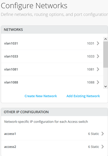
次に、図 5 に示すように、3 つの VRF を作成し、そのうちの 2 つのアクセス ネットワークを各 VRF に接続します。
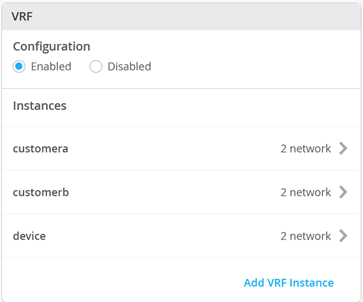
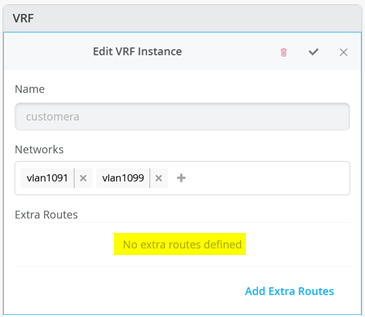
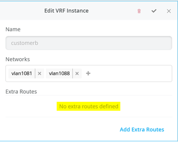
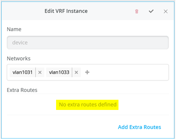
次に、各VRFに移動し、デフォルトルートなしで定義されているアクセスネットワークのみがあることを確認します。トランスポート VLAN とデフォルト ルートについては、後ほどサービス ブロック機能で定義します。 図 6、 図 7、 図 8 を参照してください。
Core1およびCore2スイッチの設定
トランスポートVLAN接続の例では、サービスブロック機能は仮想であり、コアスイッチ上に同じ場所に配置されています。そのため、2つのコアスイッチを設定する必要があります。以下の擬似コードは、core1 および core2 スイッチに適用する必要がある設定を表しています。
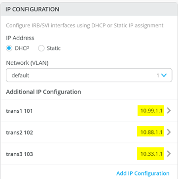
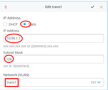
# configure the additional IP subnet 10.99.1.1/28 to network/VLAN:trans1
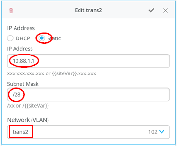
# configure the additional IP subnet 10.88.1.1/28 to network/VLAN:trans2
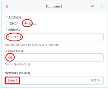
# configure the additional IP subnet 10.33.1.1/28 to network/VLAN:trans3
#
# Create a new local Port Profile called 'l2fabricexit' and configure:
# Mode='Trunk'
# Port Network (Untagged/Native VLAN)='None'
# Add the following 3 Networks as Trunk Networks:
# Network=trans1
# Network=trans2
# Network=trans3
# MTU='9018'
#
# Create a new Port configuration where:
# Port IDs=ge-0/0/3
# Interface=L2 Interface
# Configuration Profile=l2fabricexit
# Port Aggregation=Enable/Checked
# AE Index=11
# ESI-LAG=Enable/Checked
#
# Create a new Port configuration where:
# Port IDs=ge-0/0/4
# Interface=L2 Interface
# Configuration Profile=l2fabricexit
# Port Aggregation=Enable/Checked
# AE Index=12
# ESI-LAG=Enable/Checked
#
# In VRF Configuration
# Override Site/Template Settings=Checked
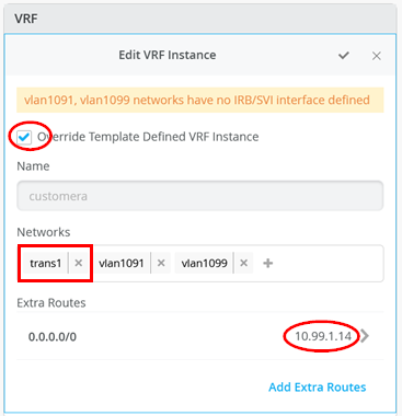
# In Instance customera
# Override Template Defined VRF Instance=Checked
# Add the Network trans1 to the existing list of networks
# Add the Extra Route 0.0.0.0/0 with via: 10.99.1.14
#
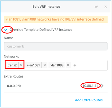
# In Instance customerb
# Override Template Defined VRF Instance=Checked
# Add the Network trans2 to the existing list of networks
# Add the Extra Route 0.0.0.0/0 with via: 10.88.1.14
#
# In Instance device
# Override Template Defined VRF Instance=Checked
# Add the Network trans3 to the existing list of networks
# Add the Extra Route 0.0.0.0/0 with via: 10.33.1.14
次の4つの画像は、以前の擬似コードから得られたMist GUI構成を示しており、各トランスポートVLANにローカルIPアドレスを割り当てるために必要な追加IP構成から始まります。
次に、アップリンクに使用する ポートプロファイル を定義します。トランクネットワーク定義にはトランスポートVLANのみを含めることが重要です。これらのVLANのみが使用され、WANルーターから見えるためです。
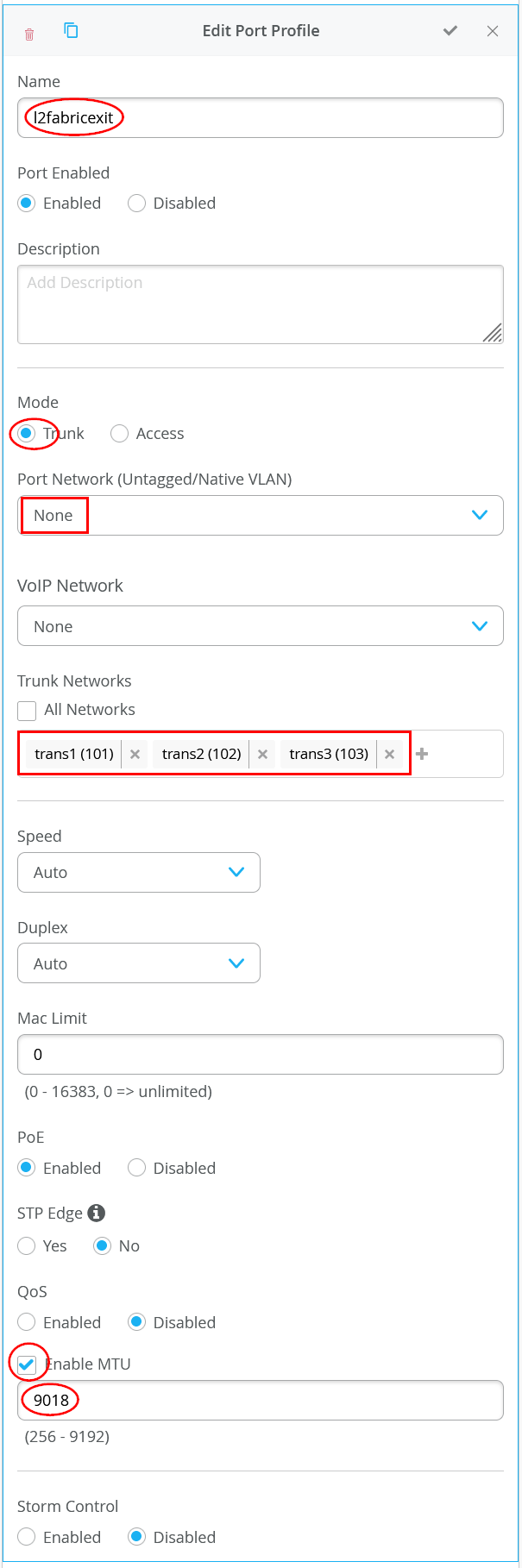 を使用してルーター WAN接続するためのポートプロファイル
次に、各アップリンクポートにポートプロファイルを割り当てます。
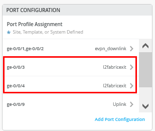 のポートプロファイル割り当て
図15は、最初のWANルーターへの最初のアップリンクの設定を示しています。
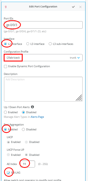
図16は、最初のWANルーターへの2番目のアップリンクの設定を示しています。
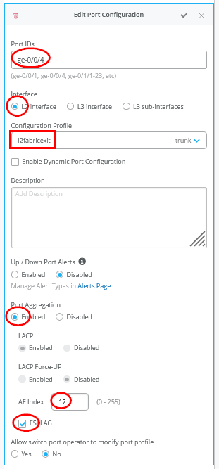
各サービスブロック機能の AEインデックス が、同じWANルーターに向けて相互に同期していることを確認し、それぞれを ESI-LAGとして定義する必要があります。また、ファブリックサービスブロックの他の場所ですでに定義されているAEインデックスを再利用しないようにする必要があります。
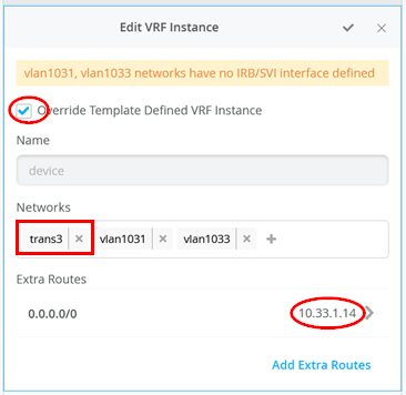
次に、ローカルVRFを作成および変更します。 これは、トランスポートVLANの終了方法のみの例外であることに注意してください。通常、ファブリックは VRF を自動的に作成します。この場合、VRF設定でサイト/テンプレート設定を上書きするチェックボックスを有効にする必要があります。 図17は、Mist GUIで必要な設定を示しています。
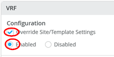 のテンプレート設定を上書きする
次に、3 つの VRS インスタンスのそれぞれで次の 3 つの設定を実行する必要があります。
- テンプレート定義のVRFインスタンスの上書きを有効にするチェックボックス
- トランスポートVLANを、事前に入力済みのアクセスVLANリストに追加します
- ゲートウェイIPアドレスがWANルーターのVRRP-VIPアドレスであるデフォルトルートを追加します。
- 図18、 図19、および図20は、3つのVRFのそれぞれのオーバーライド設定を示しています。
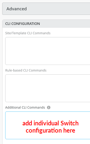
ここで、ファブリック内のトラフィックの過剰なヘアピンルーティングを回避するために、VGA設定を使用するようトランスポートVLANを変更するために追加のCLIを設定する必要があります。各サービスブロック機能スイッチのスイッチ設定で、Mist GUIの CLI設定 セクションを見つけます。必要な設定を 図21に示すフィールドに貼り付ける必要があります。
 の場所
の場所
core1スイッチのCLI設定例を次のコードブロックに示します。静的IPアドレスを仮想ゲートウェイIPアドレス+ 1(10.99.1.2)として設定しました。
# when service block function is a EX92xx change to VGA with the below
delete groups top routing-instances evpn_vs protocols evpn default-gateway do-not-advertise
set groups top routing-instances evpn_vs protocols evpn default-gateway no-gateway-community
#
# on non-EX92xx switches change to VGA with the below
# delete groups top protocols evpn default-gateway do-not-advertise
# set groups top protocols evpn default-gateway no-gateway-community
#
# modify our transport VLANs to VGA
delete interfaces irb unit 101 family inet address 10.99.1.1/28
set interfaces irb unit 101 family inet address 10.99.1.2/28 virtual-gateway-address 10.99.1.1
set interfaces irb unit 101 virtual-gateway-accept-data
set interfaces irb unit 101 virtual-gateway-v4-mac 00:00:5e:e4:05:01
#
delete interfaces irb unit 102 family inet address 10.88.1.1/28
set interfaces irb unit 102 family inet address 10.88.1.2/28 virtual-gateway-address 10.88.1.1
set interfaces irb unit 102 virtual-gateway-accept-data
set interfaces irb unit 102 virtual-gateway-v4-mac 00:00:5e:e4:05:02
#
delete interfaces irb unit 103 family inet address 10.33.1.1/28
set interfaces irb unit 103 family inet address 10.33.1.2/28 virtual-gateway-address 10.33.1.1
set interfaces irb unit 103 virtual-gateway-accept-data
set interfaces irb unit 103 virtual-gateway-v4-mac 00:00:5e:e4:05:03
core2スイッチでは、トランスポートVLANの静的IPアドレスのみが仮想ゲートウェイIPアドレス+ 2(10.88.1.3)に変更されます。
# when service block function is a EX92xx change to VGA with the below
delete groups top routing-instances evpn_vs protocols evpn default-gateway do-not-advertise
set groups top routing-instances evpn_vs protocols evpn default-gateway no-gateway-community
#
# on all non-EX92xx switches change to VGA with the below
# delete groups top protocols evpn default-gateway do-not-advertise
# set groups top protocols evpn default-gateway no-gateway-community
#
# modify our transport VLANs to VGA
delete interfaces irb unit 101 family inet address 10.99.1.1/28
set interfaces irb unit 101 family inet address 10.99.1.3/28 virtual-gateway-address 10.99.1.1
set interfaces irb unit 101 virtual-gateway-accept-data
set interfaces irb unit 101 virtual-gateway-v4-mac 00:00:5e:e4:05:01
#
delete interfaces irb unit 102 family inet address 10.88.1.1/28
set interfaces irb unit 102 family inet address 10.88.1.3/28 virtual-gateway-address 10.88.1.1
set interfaces irb unit 102 virtual-gateway-accept-data
set interfaces irb unit 102 virtual-gateway-v4-mac 00:00:5e:e4:05:02
#
#
delete interfaces irb unit 103 family inet address 10.33.1.1/28
set interfaces irb unit 103 family inet address 10.33.1.3/28 virtual-gateway-address 10.33.1.1
set interfaces irb unit 103 virtual-gateway-accept-data
set interfaces irb unit 103 virtual-gateway-v4-mac 00:00:5e:e4:05:03
なお、ジュニパーのテストラボでは、仮想EX9214スイッチをコアスイッチとして使用しました。ほとんどの実稼働環境では、EX92xxスイッチは使用しません。そのため、前の設定スニペットでコメントアウトされた2行のコメントを解除する必要があります。
# delete groups top protocols evpn default-gateway do-not-advertise
# set groups top protocols evpn default-gateway no-gateway-community
サービスブロック VRF ごとに使用する各トランスポート VLAN に対して、IRB インターフェイスで使用される仮想ゲートウェイ アドレスの MACアドレスを手動で設定する必要があります。この例では、デバッグが簡単であるため、トランスポートVLANごとに異なるMACアドレスを使用しました。
WANルーターとしてのジュニパーMX
次の CLI スニペットの例には、最初の WAN ルーターのインターフェイスの設定、VRRP ゲートウェイの冗長性、および静的ルートが含まれています。設定を完了するために、デフォルトのルートとインターフェイスを追加する必要がある場合があります。
set system host-name wanrouter1
#
set chassis aggregated-devices ethernet device-count 10
#
delete interfaces ae0
delete policy-options policy-statement fabric
delete policy-options policy-statement internet
delete routing-instances public-int
#
set protocols lldp port-id-subtype interface-name
set protocols lldp interface all
set protocols lldp-med interface all
#
delete interfaces ge-0/0/1
set interfaces ge-0/0/1 gigether-options 802.3ad ae11
delete interfaces ge-0/0/2
set interfaces ge-0/0/2 gigether-options 802.3ad ae11
delete interfaces ae11
set interfaces ae11 mtu 9018
set interfaces ae11 aggregated-ether-options lacp active
set interfaces ae11 aggregated-ether-options lacp admin-key 11
set interfaces ae11 unit 0 family bridge interface-mode trunk
set interfaces ae11 unit 0 family bridge vlan-id-list 101
set interfaces ae11 unit 0 family bridge vlan-id-list 102
set interfaces ae11 unit 0 family bridge vlan-id-list 103
#
set bridge-domains trans1 vlan-id 101
set bridge-domains trans1 routing-interface irb.101
set bridge-domains trans2 vlan-id 102
set bridge-domains trans2 routing-interface irb.102
set bridge-domains trans3 vlan-id 103
set bridge-domains trans3 routing-interface irb.103
#
set interfaces irb unit 101 family inet address 10.99.1.13/28 vrrp-group 1 virtual-address 10.99.1.14
set interfaces irb unit 101 family inet address 10.99.1.13/28 vrrp-group 1 priority 110
set interfaces irb unit 101 family inet address 10.99.1.13/28 vrrp-group 1 accept-data
#
set interfaces irb unit 102 family inet address 10.88.1.13/28 vrrp-group 2 virtual-address 10.88.1.14
set interfaces irb unit 102 family inet address 10.88.1.13/28 vrrp-group 2 priority 110
set interfaces irb unit 102 family inet address 10.88.1.13/28 vrrp-group 2 accept-data
#
set interfaces irb unit 103 family inet address 10.33.1.13/28 vrrp-group 3 virtual-address 10.33.1.14
set interfaces irb unit 103 family inet address 10.33.1.13/28 vrrp-group 3 priority 110
set interfaces irb unit 103 family inet address 10.33.1.13/28 vrrp-group 3 accept-data
#
set routing-options static route 10.99.91.0/24 next-hop 10.99.1.1
set routing-options static route 10.99.99.0/24 next-hop 10.99.1.1
set routing-options static route 172.16.193.0/24 next-hop 10.99.1.1
#
set routing-options static route 10.88.81.0/24 next-hop 10.88.1.1
set routing-options static route 10.88.88.0/24 next-hop 10.88.1.1
set routing-options static route 172.16.194.0/24 next-hop 10.88.1.1
#
set routing-options static route 10.33.31.0/24 next-hop 10.33.1.1
set routing-options static route 10.33.33.0/24 next-hop 10.33.1.1
set routing-options static route 172.16.195.0/24 next-hop 10.33.1.1
2 番目の WAN ルーターでは、AE キーとインデックス、静的 IP アドレスが設定に大きく変更されています。
set system host-name wanrouter2
#
set chassis aggregated-devices ethernet device-count 10
#
set protocols lldp port-id-subtype interface-name
set protocols lldp interface all
set protocols lldp-med interface all
#
delete interfaces ge-0/0/1
set interfaces ge-0/0/1 gigether-options 802.3ad ae12
delete interfaces ge-0/0/2
set interfaces ge-0/0/2 gigether-options 802.3ad ae12
#
delete interfaces ae12
set interfaces ae12 mtu 9018
set interfaces ae12 aggregated-ether-options lacp active
set interfaces ae12 aggregated-ether-options lacp admin-key 12
set interfaces ae12 unit 0 family bridge interface-mode trunk
set interfaces ae12 unit 0 family bridge vlan-id-list 101
set interfaces ae12 unit 0 family bridge vlan-id-list 102
set interfaces ae12 unit 0 family bridge vlan-id-list 103
#
set bridge-domains trans1 vlan-id 101
set bridge-domains trans1 routing-interface irb.101
set bridge-domains trans2 vlan-id 102
set bridge-domains trans2 routing-interface irb.102
set bridge-domains trans3 vlan-id 103
set bridge-domains trans3 routing-interface irb.103
#
set interfaces irb unit 101 family inet address 10.99.1.12/28 vrrp-group 1 virtual-address 10.99.1.14
set interfaces irb unit 101 family inet address 10.99.1.12/28 vrrp-group 1 accept-data
#
set interfaces irb unit 102 family inet address 10.88.1.12/28 vrrp-group 2 virtual-address 10.88.1.14
set interfaces irb unit 102 family inet address 10.88.1.12/28 vrrp-group 2 accept-data
#
set interfaces irb unit 103 family inet address 10.33.1.12/28 vrrp-group 3 virtual-address 10.33.1.14
set interfaces irb unit 103 family inet address 10.33.1.12/28 vrrp-group 3 accept-data
#
set routing-options static route 10.99.91.0/24 next-hop 10.99.1.1
set routing-options static route 10.99.99.0/24 next-hop 10.99.1.1
set routing-options static route 172.16.193.0/24 next-hop 10.99.1.1
#
set routing-options static route 10.88.81.0/24 next-hop 10.88.1.1
set routing-options static route 10.88.88.0/24 next-hop 10.88.1.1
set routing-options static route 172.16.194.0/24 next-hop 10.88.1.1
#
set routing-options static route 10.33.31.0/24 next-hop 10.33.1.1
set routing-options static route 10.33.33.0/24 next-hop 10.33.1.1
set routing-options static route 172.16.195.0/24 next-hop 10.33.1.1
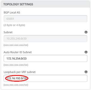
172.16.19x.0の範囲の静的ルートについて疑問に思うかもしれません。IP Closはエニーキャストファブリックであることを忘れないでください。そのため、DHCPリレーがファブリックオーバーレイでIPアドレスを使用する場合に備えて、スタティックルートを用意しておく必要があります。定義例については、図22を参照してください
 ごとのループバック
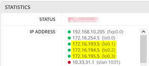
オーバーレイループバックIPは、スイッチ上の各VRFに/24の範囲として割り当てられます。 図23に示すように、ファブリックアクセススイッチを見れば理解できます。したがって、必要な到達可能性を実現するには、VRFに接続された他の追加VLANと同様に、これらをマッピングし直す必要があります。
以下のコマンドは、WAN ルーター 1 上の接続をデバッグするのに役立ちます。
root@wanrouter1> show lldp neighbors
Local Interface    Parent Interface    Chassis Id                               Port info          System Name
ge-0/0/0           -                   4c:96:14:95:09:80                        516                 internet
ge-0/0/1           ae11                2c:6b:f5:3a:42:c0                        ge-0/0/3            core1
ge-0/0/2           ae11                2c:6b:f5:7f:7d:c0                        ge-0/0/3            core2
.
root@wanrouter1> show lacp interfaces
Aggregated interface: ae11
    LACP state:           Role   Exp   Def  Dist  Col  Syn  Aggr  Timeout  Activity
      ge-0/0/1           Actor    No    No   Yes  Yes  Yes   Yes     Fast    Active
      ge-0/0/1         Partner    No    No   Yes  Yes  Yes   Yes     Fast    Active
      ge-0/0/2           Actor    No    No   Yes  Yes  Yes   Yes     Fast    Active
      ge-0/0/2         Partner    No    No   Yes  Yes  Yes   Yes     Fast    Active
    LACP protocol:        Receive State  Transmit State          Mux State
      ge-0/0/1                  Current   Fast periodic Collecting distributing
      ge-0/0/2                  Current   Fast periodic Collecting distributing
.
root@wanrouter1> show vrrp
Interface     State       Group   VR state VR Mode   Timer    Type   Address
irb.101       up              1   master   Active      A  0.350 lcl    10.99.1.13
                                                                vip    10.99.1.14
irb.102       up              2   master   Active      A  0.625 lcl    10.88.1.13
                                                                vip    10.88.1.14
irb.103       up              3   master   Active      A  0.830 lcl    10.33.1.13
                                                                vip    10.33.1.14
次のコマンドは、WANルーター2上の接続をデバッグするのに役立ちます。
root@wanrouter2> show lldp neighbors
Local Interface    Parent Interface    Chassis Id                               Port info          System Name
ge-0/0/0           -                   4c:96:14:95:09:80                        517                 internet
ge-0/0/1           ae12                2c:6b:f5:3a:42:c0                        ge-0/0/4            core1
ge-0/0/2           ae12                2c:6b:f5:7f:7d:c0                        ge-0/0/4            core2
.
root@wanrouter2> show lacp interfaces
Aggregated interface: ae12
    LACP state:           Role   Exp   Def  Dist  Col  Syn  Aggr  Timeout  Activity
      ge-0/0/1           Actor    No    No   Yes  Yes  Yes   Yes     Fast    Active
      ge-0/0/1         Partner    No    No   Yes  Yes  Yes   Yes     Fast    Active
      ge-0/0/2           Actor    No    No   Yes  Yes  Yes   Yes     Fast    Active
      ge-0/0/2         Partner    No    No   Yes  Yes  Yes   Yes     Fast    Active
    LACP protocol:        Receive State  Transmit State          Mux State
      ge-0/0/1                  Current   Fast periodic Collecting distributing
      ge-0/0/2                  Current   Fast periodic Collecting distributing
.
root@wanrouter2> show vrrp
Interface     State       Group   VR state VR Mode   Timer    Type   Address
irb.101       up              1   backup   Active      D  2.811 lcl    10.99.1.12
                                                                vip    10.99.1.14
                                                                mas    10.99.1.13
irb.102       up              2   backup   Active      D  3.303 lcl    10.88.1.12
                                                                vip    10.88.1.14
                                                                mas    10.88.1.13
irb.103       up              3   backup   Active      D  2.798 lcl    10.33.1.12
                                                                vip    10.33.1.14
                                                                mas    10.33.1.13
eBGPルーティングプロトコルを使用したL3出口
キャンパスファブリックでVLANまたはVRFの作成を作成するときは、次のベストプラクティスを覚えておいてください。
- スイッチテンプレートですべてのVLANを作成し、 キャンパスファブリックダイアログにインポートします。Mist GUIの他の場所にVLANを作成すると、最終的に一貫性が失われ、問題の解決が困難になります。
- 必要に応じて、ファブリックは必要なVRFを作成します。Mist GUIの他の場所にVRFを手動で作成しないでください。
- スイッチテンプレート内にポートプロファイルを作成し、変更がファブリック内のすべてのスイッチで同期されるようにすることをお勧めします。
開始する前に、次の計画が必要です。
- ルーティングプロトコルとルート交換の実装方法
- P2Pリンクの設定方法
- VRFの識別に間接的に使用されるVLAN割り当てを分散する方法
VRFがすでにファブリック内の他の場所(IP Closのアクセススイッチ上など)存在する場合でも、L3の出口を実行すると、すべてのサービスブロック機能で自動的に再作成されます。
サービスブロック機能でVRFを自動的に作成するために、各WANルーターでVRF上のVLAN名を再利用する必要があります。ローカルP2Pリンクを定義してVLANを再利用する場合、それらの定義は純粋にローカルであるため、オーバーレイVLAN定義と矛盾しないことに注意してください。また、ここで特別なトランスポートVLANを定義する必要はありません。ただし、ニーズに合えば、P2Pリンクに特別なトランスポートVLANを使用して定義することもできます。
P2Pリンクを定義する際には、ファブリックで使用されているアドレス範囲外であることを確認する必要があります。これらのリンクに対してファブリックが使用するデフォルト範囲は 10.255.240.0/20 です。/31 ネットマスクを使用することをお勧めします。このプランでは、WAN ルーター側には偶数の IP アドレス、ファブリック側には奇数の IP アドレスを使用できます。
システムでは、物理ケーブル上の各P2PリンクにVLANを使用する必要があります。これにより、1本のアップリンクケーブルで複数のVRFを多重化できます。VLANは内部的にVRFを参照していることに注意してください。
eBGPでは、ピアリング用に独自のプライベートASNも定義する必要があります。ハードコードされたデフォルトでは、ファブリックはEVPNコントロールプレーンに65000 ASNを使用し、65001で設定可能なASNの割り当てを開始します。その後、ノードごとに 1 桁進みます。そのため、システム割り当てASNとの競合を避けるために、65000未満のASN値を使用することを推奨します。QFXスイッチでは、16のローカルASNしか許可されません。そのため、すべてのVRF間で共有ASNを使用することをお勧めします。しかし、この例では、WANルーターごとに異なるASNを使用することにしました。
図24は、ファブリックの2つのサービスブロック機能が最初のWANルーターにどのように接続するかを示しています。
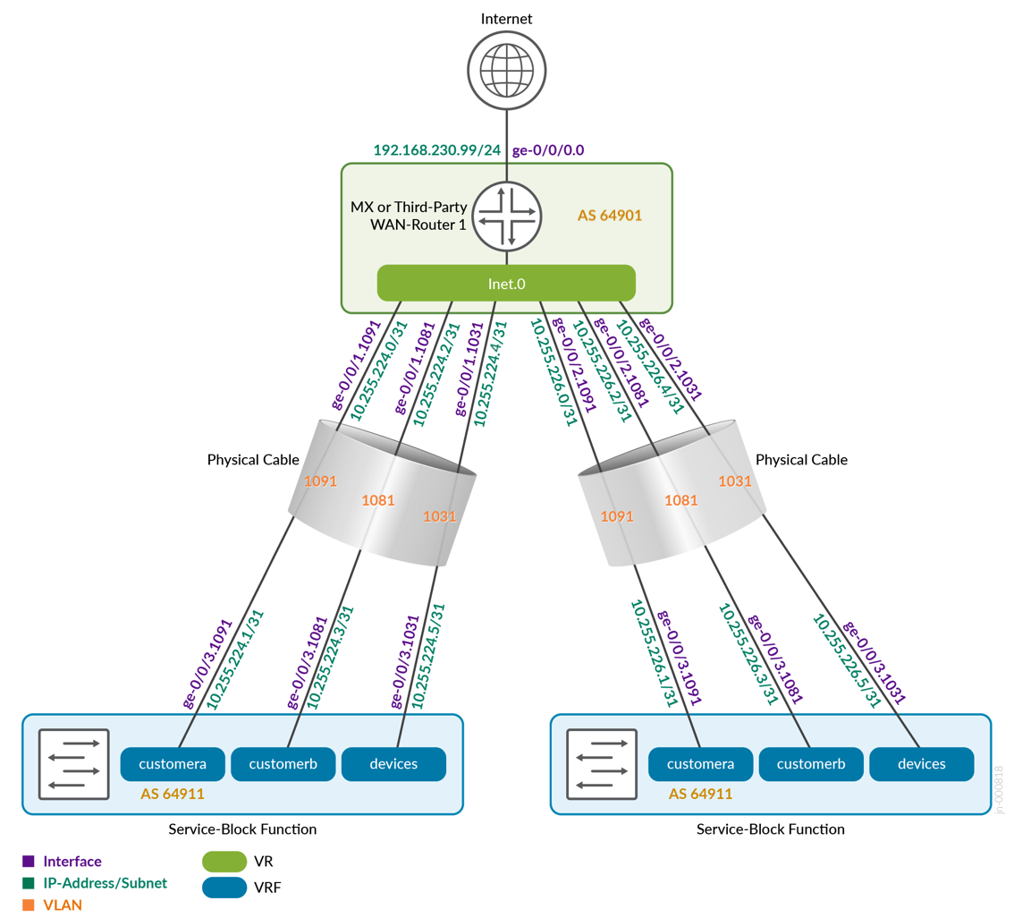 へのL3 eBGPベースのファブリック
図25は、ファブリックの2つのサービスブロック機能が2番目のWANルーターにどのように接続するかを示しています。各 VRF の VLAN の 2 番目のブロックが使用されていることに注意してください。
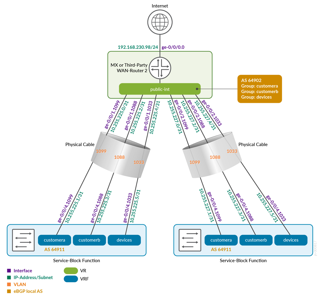 をWANするL3 eBGPベースのファブリック
表1は、サービスブロック機能としてのコア1スイッチとコア2スイッチ、および2台のWANルーター間の完全な構成を示しています。eBGPに選択したASNも確認できます。
| スイッチ | スイッチAS | VRF | コアP2P IP | コアIF | WANルーター | WANルーターP2P IP | WANルーターAS | WANルーターのIF | VLAN ID |
|---|---|---|---|---|---|---|---|---|---|
| コア1 | 64911 | カスタマーA | 10.255.224.1/31 | ge-0/0/3.1091 | WANルーター1 | 10.255.224.0/31 | 64901 | ge-0/0/1.1091 | 1091 |
| コア1 | 64911 | カスタマーB | 10.255.224.3/31 | ge-0/0/3.1081 | WANルーター1 | 10.255.224.2/31 | 64901 | ge-0/0/1.1081 | 1081 |
| コア1 | 64911 | デバイス | 10.255.224.5/31 | ge-0/0/3.1031 | WANルーター1 | 10.255.224.4/31 | 64901 | ge-0/0/1.1031 | 1031 |
| コア1 | 64911 | カスタマーA | 10.255.225.1/31 | ge-0/0/4.1099 | WANルーター2 | 10.255.225.0/31 | 64902 | ge-0/0/1.1099 | 1099 |
| コア1 | 64911 | カスタマーB | 10.255.225.3/31 | ge-0/0/4.1088 | WANルーター2 | 10.255.225.2/31 | 64902 | ge-0/0/1.1088 | 1088 |
| コア1 | 64911 | デバイス | 10.255.225.5/31 | ge-0/0/4.1033 | WANルーター2 | 10.255.225.4/31 | 64902 | ge-0/0/1.1033 | 1033 |
| コア2 | 64911 | カスタマーA | 10.255.226.1/31 | ge-0/0/3.1091 | WANルーター1 | 10.255.226.0/31 | 64901 | ge-0/0/2.1091 | 1091 |
| コア2 | 64911 | カスタマーB | 10.255.226.3/31 | ge-0/0/3.1081 | WANルーター1 | 10.255.226.2/31 | 64901 | ge-0/0/2.1081 | 1081 |
| コア2 | 64911 | デバイス | 10.255.226.5/31 | ge-0/0/3.1031 | WANルーター1 | 10.255.226.4/31 | 64901 | ge-0/0/2.1031 | 1031 |
| コア2 | 64911 | カスタマーA | 10.255.227.1/31 | ge-0/0/4.1099 | WANルーター2 | 10.255.227.0/31 | 64902 | ge-0/0/2.1099 | 1099 |
| コア2 | 64911 | カスタマーB | 10.255.227.3/31 | ge-0/0/4.1088 | WANルーター2 | 10.255.227.2/31 | 64902 | ge-0/0/2.1088 | 1088 |
| コア2 | 64911 | デバイス | 10.255.227.5/31 | ge-0/0/4.1033 | WANルーター2 | 10.255.227.4/31 | 64902 | ge-0/0/2.1033 | 1033 |
以下のコードブロックは、このファブリックで使用されるスイッチテンプレートのエクスポートされたバージョンを示しています。これにより、インポート時に設定を確認できます。ご覧のとおり、VRFごとに最低2つのVLANがあります。L3出口モデルでは、WANルーターとVRFごとに1つのVLANが必要であることに留意してください)。
{
  "additional_config_cmds": [],
  "networks": {
    "vlan1099": {
      "vlan_id": 1099,
      "subnet": "10.99.99.0/24"
    },
    "vlan1088": {
      "vlan_id": 1088,
      "subnet": "10.88.88.0/24"
    },
    "vlan1033": {
      "vlan_id": 1033,
      "subnet": "10.33.33.0/24"
    },
    "vlan1091": {
      "vlan_id": 1091,
      "subnet": "10.99.91.0/24"
    },
    "vlan1081": {
      "vlan_id": 1081,
      "subnet": "10.88.81.0/24"
    },
    "vlan1031": {
      "vlan_id": 1031,
      "subnet": "10.33.31.0/24"
    }
  },
  "port_usages": {
    "vlan1099": {
      "mode": "access",
      "disabled": false,
      "port_network": "vlan1099",
      "voip_network": null,
      "stp_edge": false,
      "mac_auth_protocol": null,
      "all_networks": false,
      "networks": null,
      "port_auth": null,
      "enable_mac_auth": null,
      "mac_auth_only": null,
      "guest_network": null,
      "bypass_auth_when_server_down": null,
      "speed": "auto",
      "duplex": "auto",
      "mac_limit": 0,
      "persist_mac": false,
      "poe_disabled": false,
      "enable_qos": false,
      "storm_control": {},
      "mtu": null,
      "description": "",
      "disable_autoneg": false
    },
    "vlan1088": {
      "mode": "access",
      "disabled": false,
      "port_network": "vlan1088",
      "voip_network": null,
      "stp_edge": false,
      "mac_auth_protocol": null,
      "all_networks": false,
      "networks": null,
      "port_auth": null,
      "enable_mac_auth": null,
      "mac_auth_only": null,
      "guest_network": null,
      "bypass_auth_when_server_down": null,
      "speed": "auto",
      "duplex": "auto",
      "mac_limit": 0,
      "persist_mac": false,
      "poe_disabled": false,
      "enable_qos": false,
      "storm_control": {},
      "mtu": null,
      "description": "",
      "disable_autoneg": false
    },
    "dynamic": {
      "mode": "dynamic",
      "reset_default_when": "link_down",
      "rules": []
    }
  },
  "switch_matching": {
    "enable": true,
    "rules": []
  },
  "switch_mgmt": {
    "config_revert_timer": 10,
    "root_password": "<password>",
    "protect_re": {
      "enabled": false
    },
    "tacacs": {
      "enabled": false
    }
  },
  "mist_nac": {
    "enabled": true,
    "network": null
  },
  "radius_config": {
    "auth_servers": [],
    "acct_servers": [],
    "auth_servers_timeout": 5,
    "auth_servers_retries": 3,
    "fast_dot1x_timers": false,
    "acct_interim_interval": 0,
    "auth_server_selection": "ordered",
    "coa_enabled": false,
    "coa_port": ""
  },
  "vrf_config": {
    "enabled": false
  },
  "remote_syslog": {
    "enabled": false
  },
  "snmp_config": {
    "enabled": false
  },
  "dhcp_snooping": {
    "enabled": false
  },
  "dns_servers": [],
  "dns_suffix": [],
  "ntp_servers": [],
  "acl_policies": [],
  "port_mirroring": {},
  "name": "campus-fabric"
}
キャンパスファブリック設定ダイアログ内に、ネットワークの設定というページがあります。ここで、スイッチテンプレートから6つのVLANをインポートします。その結果、設定を次の図に示します。
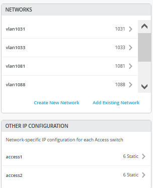
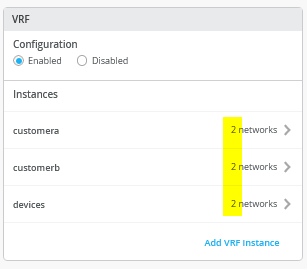 に2つのネットワークを接続する
次に、各VRFに移動して、手動ルートをすべて削除します。後でVRFを識別するため、各VRFに少なくとも2つのVLANが接続されていることを確認してください。
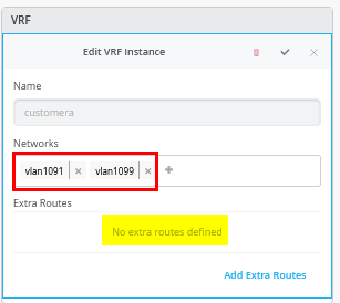
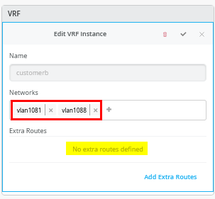
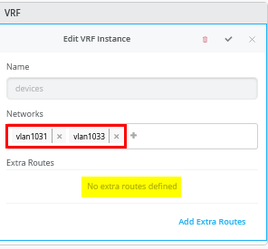
Core1 スイッチの設定
この例では、サービスブロック機能は仮想であり、コアスイッチ上に同じ場所に配置されています。そのため、2つのコアスイッチを設定する必要があります。以下の疑似コードブロックは、core1スイッチで設定する必要がある内容を説明しています。
# configure the Additional IP-Subnet 10.255.224.1 255.255.255.254 to Network/VLAN:vlan1091
# configure the Additional IP-Subnet 10.255.224.3 255.255.255.254 to Network/VLAN:vlan1081
# configure the Additional IP-Subnet 10.255.224.5 255.255.255.254 to Network/VLAN:vlan1031
# Then bind these 3 Network/VLANs to Port Interface ge-0/0/3 as L3-Sub-Interfaces with MTU=9018
#
# configure the Additional IP-Subnet 10.255.225.1 255.255.255.254 to Network/VLAN:vlan1099
# configure the Additional IP-Subnet 10.255.225.3 255.255.255.254 to Network/VLAN:vlan1088
# configure the Additional IP-Subnet 10.255.225.5 255.255.255.254 to Network/VLAN:vlan1033
# Then bind these 3 Network/VLANs to Port Interface ge-0/0/4 as L3-Sub-Interfaces with MTU=9018
#
# Enable BGP
# Create an Export policy called 'export-vrfs'
# Add to this export Policy the following Networks as:
# - Add Term w. Name=fabric-all-no-hosts  Prefix=0.0.0.0/0-30  Protocol=None  Then=Accept
# - Add Term w. Name=overlaylo0 Prefix=172.16.192.0/24-32  Protocol=None  Then=Accept
#
# Create an Export policy called 'import-default'
# - Name=default  Prefix=0.0.0.0/0  Protocol=BGP  Action=Accept
#
# Create a BGP Group with:
# - Name=customera0
# - Type=External
# - Network (VLAN)=vlan1091
# - BFD interval=1000
# - Local AS=64911
# - Hold Time=90
# - Set Export=export-vrfs and Import=import-default
# Add also the following Neighbor
# - IP_Address=10.255.224.0  Neighbor_AS=64901  Hold-Time=90
#
# Create a BGP Group with:
# - Name=customerb0
# - Type=External
# - Network (VLAN)=vlan1081
# - BFD interval=1000
# - Local AS=64911
# - Hold Time=90
# - Set Export=export-vrfs and Import=import-default
# Add also the following Neighbor
# - IP_Address=10.255.224.2  Neighbor_AS=64901  Hold-Time=90
#
# Create a BGP Group with:
# - Name=devices0
# - Type=External
# - Network (VLAN)=vlan1031
# - BFD interval=1000
# - Local AS=64911
# - Hold Time=90
# - Set Export=export-vrfs and Import=import-default
# Add also the following Neighbor
# - IP_Address=10.255.224.4  Neighbor_AS=64901  Hold-Time=90
#
# Create a BGP Group with:
# - Name=customera1
# - Type=External
# - Network (VLAN)=vlan1099
# - BFD interval=1000
# - Local AS=64911
# - Hold Time=90
# - Set Export=export-vrfs and Import=import-default
# Add also the following Neighbor
# - IP_Address=10.255.225.0  Neighbor_AS=64902  Hold-Time=90
#
# Create a BGP Group with:
# - Name=customerb1
# - Type=External
# - Network (VLAN)=vlan1088
# - BFD interval=1000
# - Local AS=64911
# - Hold Time=90
# - Set Export=export-vrfs and Import=import-default
# Add also the following Neighbor
# - IP_Address=10.255.225.2  Neighbor_AS=64902  Hold-Time=90
#
# Create a BGP Group with:
# - Name=devices1
# - Type=External
# - Network (VLAN)=vlan1033
# - BFD interval=1000
# - Local AS=64911
# - Hold Time=90
# - Set Export=export-vrfs and Import=import-default
# Add also the following Neighbor
# - IP_Address=10.255.225.4  Neighbor_AS=64902  Hold-Time=90
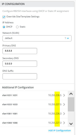
次のスクリーンショットは、以前の設定をMist GUIに変換したものです。まず、追加の IP 設定から始めます。VLAN の IP アドレスが、これらの VLAN が元々オーバーレイに含まれていた IP アドレスと一致しないことに注意してください。これは仕様によるものです。VRFへの参照として常にVLANを用意する必要があります。
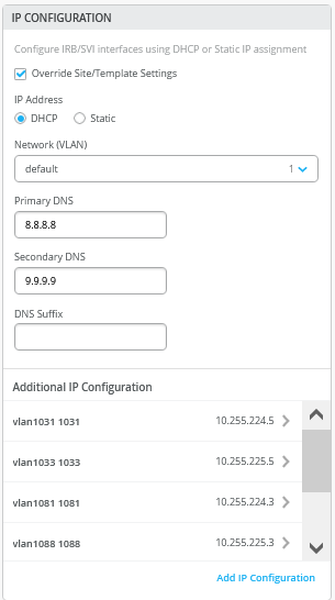
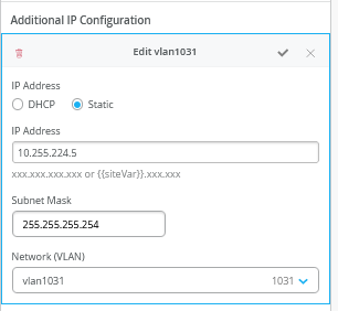 を設定する6つのVLANのうちの1つ
ポート設定ウィンドウで、L3サブインターフェイスを有効にし、定義された最初の3つのサブインターフェイスを割り当てる必要があります。
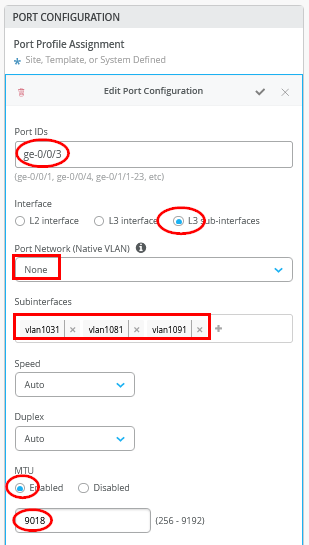
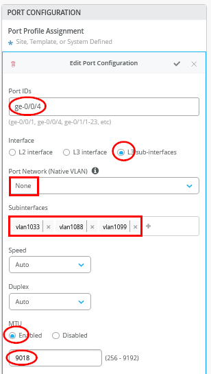
2番目の ポート設定 ウィンドウで、もう一方のWANルーターに向けて、定義された2番目の3つのサブインターフェイスを割り当てます。
次に、6つのピアすべて(3つのVRFと2つのWANルーター)を含むeBGP設定全体を入力する必要があります。完了すると、概要ページは図33のようになります。
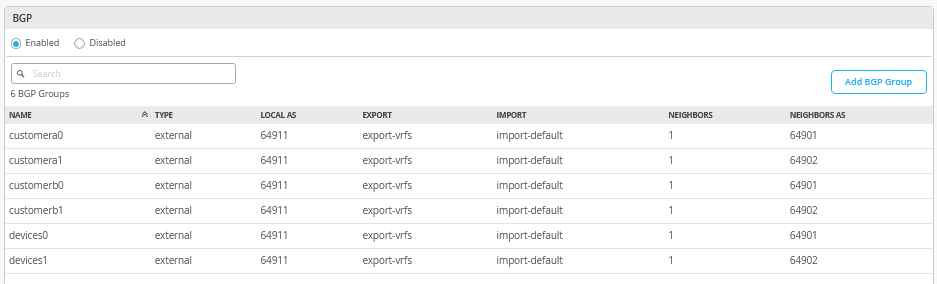
まず、2つのルーティングポリシーを定義し、その概要を上の表に示します。
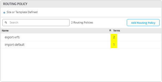
この例では、エクスポート ルート ポリシーに次の条件が含まれています。
- Term=fabric-all-no-hosts — 設定されたすべてのVRFとそのVLANからファブリックのすべてのルートを自動的にエクスポートするために使用されます。潜在的なP2Pリンクとシングルホストルートを削除します。これを実現するために、プレフィックス「0.0.0.0/0-30」を使用します。プレフィックスに「0-30」を使用することは、Junos OSで「orlonger」を定義する方法です。
- Term=overlaylo0 — 通常はlo0.xに個別に割り当てられるオーバーレイループバックIPアドレス(DHCPリレー使用の場合)をホストIPレベルまでエクスポートするために使用されます。これを実現するには、172.16.192.0/24-32 を使用します。ここではホストレベルに移動する必要がありますが、上記のステートメントでは行いません。
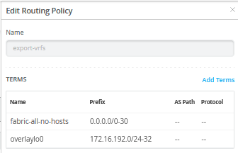
必要に応じて、「0.0.0.0/0-32」などの単一の用語を使用してルールセットを簡素化できます。この用語では、ホストIPアドレスで表されるファブリック内の個々のクライアントのルートを含む、すべてのルートがエクスポートされます。このアプローチはデバッグにも役立ちます。WAN ルーターの AS パス情報を調べると、どの EVPN ファブリック スイッチが特定のホスト IP を通知しているかが明らかになるためです。
ただし欠点は、このアプローチでは大量のルートがWANルーターと交換される可能性があるのに対し、デフォルト設定の「0.0.0.0/0-30」では、ルート共有が設定されたVLANにのみ関連付けられたプレフィックスに制限される可能性があることです。
10.99.99.0/24      *[BGP/170] 00:06:46, localpref 100, from 10.255.226.1
                      AS path: 64911 65001 65004 65005 I, validation-state: unverified
                       to 10.255.224.1 via ge-0/0/2.1091
                       to 10.255.226.1 via ge-0/0/3.1091
                    >  to 10.255.225.1 via ge-7/0/2.1099
                       to 10.255.227.1 via ge-7/0/3.1099
                    [BGP/170] 00:06:50, localpref 100
                      AS path: 64911 65002 65004 65005 I, validation-state: unverified
                    >  to 10.255.224.1 via ge-0/0/2.1091
                    [BGP/170] 00:12:38, localpref 100
                      AS path: 64911 65002 65004 65005 I, validation-state: unverified
                    >  to 10.255.225.1 via ge-7/0/2.1099
                    [BGP/170] 00:06:46, localpref 100
                      AS path: 64911 65001 65004 65005 I, validation-state: unverified
                    >  to 10.255.227.1 via ge-7/0/3.1099
10.99.99.99/32     *[BGP/170] 00:00:14, localpref 100, from 10.255.224.1
                      AS path: 64911 65002 65003 65006 I, validation-state: unverified
                       to 10.255.224.1 via ge-0/0/2.1091
                       to 10.255.226.1 via ge-0/0/3.1091
                    >  to 10.255.225.1 via ge-7/0/2.1099
                       to 10.255.227.1 via ge-7/0/3.1099
                    [BGP/170] 00:01:33, localpref 100
                      AS path: 64911 65002 65003 65006 I, validation-state: unverified
                    >  to 10.255.225.1 via ge-7/0/2.1099
                    [BGP/170] 00:00:14, localpref 100
                      AS path: 64911 65001 65003 65006 I, validation-state: unverified
                    >  to 10.255.226.1 via ge-0/0/3.1091
                    [BGP/170] 00:00:14, localpref 100
                      AS path: 64911 65001 65003 65006 I, validation-state: unverified
                    >  to 10.255.227.1 via ge-7/0/3.1099
インポートポリシーは、WANルーターからデフォルトルートをインポートします。
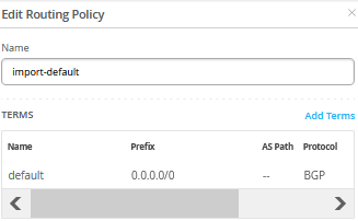
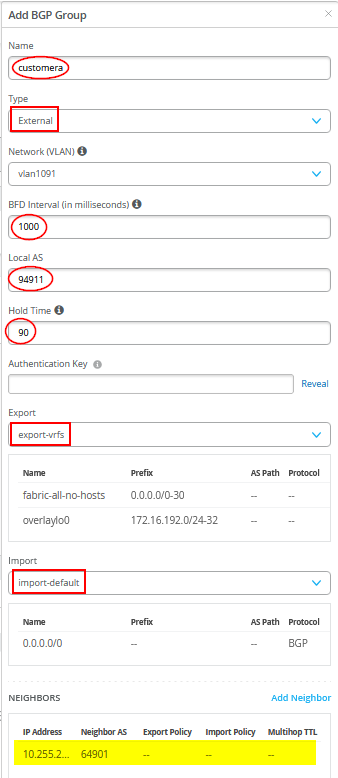
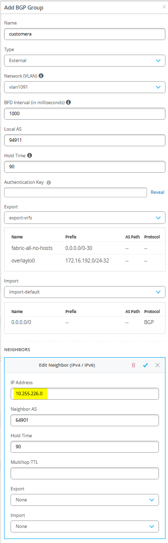
図35 は、必要なエントリが呼び出された単一のBGPピアリングエントリの設定を示しています。
 BGP例
BGP例
また、WAN ルーターを BGP ネイバーとして定義する必要があります。
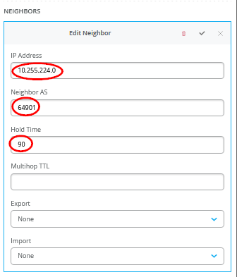
図 36 に示すように警告メッセージが表示される場合があります。それらは無視しても問題ありません。

- 上記のメッセージが表示されるのは、すでにVRFに割り当てられているオーバーレイVLANをWANルーターとのアンダーレイBGPピアリングに再利用しているためです。これは、ファブリックの VRF 設定に含まれていない BGP ピアリング専用 VLAN を使用することで回避できます。そのためには、「トランスポートVLANを使用したL2出口」アプローチと同様のローカルVRF設定が必要です。これには、標準ファブリック設定ダイアログで設定されたオーバーレイVLANとともに、各VRFにBGPピアリングVLANを手動で追加する必要があります。
- この方法では誤検知のエラーメッセージを排除できますが、トレードオフがあります。新しいVLANがファブリックに追加されるたびに、各サービスブロックを手動で更新して、カスタムローカルVRF設定に新しいVLANを含める必要があります。
- 対照的に、このJVD-Eで採用されている方法では、このようなエラーが発生しやすい再設定を回避できます。新しいVLANをスイッチテンプレートに追加し、ファブリックダイアログで設定するだけです。サービスブロックの設定は変更されず、上記のエクスポートフィルター設定に基づいて新しいVLANのルートを自動的にエクスポートします。
Core2 スイッチの設定
以下の擬似コードは、core2 スイッチに適用する必要がある設定を表しています。
# configure the Additional IP-Subnet 10.255.226.1 255.255.255.254 to Network/VLAN:vlan1091
# configure the Additional IP-Subnet 10.255.226.3 255.255.255.254 to Network/VLAN:vlan1081
# configure the Additional IP-Subnet 10.255.226.5 255.255.255.254 to Network/VLAN:vlan1031
# Then bind these 3 Network/VLANs to Port Interface ge-0/0/3 as L3-Sub-Interfaces with MTU=9018
#
# configure the Additional IP-Subnet 10.255.227.1 255.255.255.254 to Network/VLAN:vlan1099
# configure the Additional IP-Subnet 10.255.227.3 255.255.255.254 to Network/VLAN:vlan1088
# configure the Additional IP-Subnet 10.255.227.5 255.255.255.254 to Network/VLAN:vlan1033
# Then bind these 3 Network/VLANs to Port Interface ge-0/0/4 as L3-Sub-Interfaces with MTU=9018
#
# Enable BGP
# Create an Export policy called 'export-vrfs'
# Add to this export Policy the following Networks as:
# - Add Term w. Name=fabric-all-no-hosts  Prefix=0.0.0.0/0-30  Protocol=None  Then=Accept
# - Add Term w. Name=overlaylo0 Prefix=172.16.192.0/24-32  Protocol=None  Then=Accept
#
# Create an Export policy called 'import-default'
# - Name=default  Prefix=0.0.0.0/0  Protocol=BGP  Action=Accept
#
# Create a BGP Group with:
# - Name=customera0
# - Type=External
# - Network (VLAN)=vlan1091
# - BFD interval=1000
# - Local AS=64911
# - Hold Time=90
# - Set Export=export-vrfs and Import=import-default
# Add also the following Neighbor
# - IP_Address=10.255.226.0  Neighbor_AS=64901  Hold-Time=90
#
# Create a BGP Group with:
# - Name=customerb0
# - Type=External
# - Network (VLAN)=vlan1081
# - BFD interval=1000
# - Local AS=64911
# - Hold Time=90
# - Set Export=export-vrfs and Import=import-default
# Add also the following Neighbor
# - IP_Address=10.255.226.2  Neighbor_AS=64901  Hold-Time=90
#
# Create a BGP Group with:
# - Name=devices0
# - Type=External
# - Network (VLAN)=vlan1031
# - BFD interval=1000
# - Local AS=64911
# - Hold Time=90
# - Set Export=export-vrfs and Import=import-default
# Add also the following Neighbor
# - IP_Address=10.255.226.4  Neighbor_AS=64901  Hold-Time=90
#
# Create a BGP Group with:
# - Name=customera1
# - Type=External
# - Network (VLAN)=vlan1099
# - BFD interval=1000
# - Local AS=64911
# - Hold Time=90
# - Set Export=export-vrfs and Import=import-default
# Add also the following Neighbor
# - IP_Address=10.255.227.0  Neighbor_AS=64902  Hold-Time=90
#
# Create a BGP Group with:
# - Name=customerb1
# - Type=External
# - Network (VLAN)=vlan1088
# - BFD interval=1000
# - Local AS=64911
# - Hold Time=90
# - Set Export=export-vrfs and Import=import-default
# Add also the following Neighbor
# - IP_Address=10.255.227.2  Neighbor_AS=64902  Hold-Time=90
#
# Create a BGP Group with:
# - Name=devices1
# - Type=External
# - Network (VLAN)=vlan1033
# - BFD interval=1000
# - Local AS=64911
# - Hold Time=90
# - Set Export=export-vrfs and Import=import-default
# Add also the following Neighbor
# - IP_Address=10.255.227.4  Neighbor_AS=64902  Hold-Time=90
P2PサブネットとBGPネイバーを除き、core2スイッチの設定はcore1スイッチの設定と同じです。
WANルーターとしてのジュニパーMX
以下のいくつかのコードブロックは、P2PインターフェイスのJunos OS CLI設定、すべてのBGPネイバーを含むeBGP設定全体、各WANルーターのすべてのインポートおよびエクスポートルートポリシーを示しています。ファブリックに信号を送る必要があるため、設定を完了するためにデフォルトのルートとインターフェイスを追加する必要がある場合がありますが、デバイスがどのようにしてそれらを知るようになるかは不明です。
最初の WAN ルーターの CLI 設定:
set system host-name wanrouter1
#
delete interfaces ge-0/0/1
set interfaces ge-0/0/1 flexible-vlan-tagging
set interfaces ge-0/0/1 mtu 9014
set interfaces ge-0/0/1 unit 1091 description vlan1091
set interfaces ge-0/0/1 unit 1091 vlan-id 1091
set interfaces ge-0/0/1 unit 1091 family inet address 10.255.224.0/31
set interfaces ge-0/0/1 unit 1081 description vlan1081
set interfaces ge-0/0/1 unit 1081 vlan-id 1081
set interfaces ge-0/0/1 unit 1081 family inet address 10.255.224.2/31
set interfaces ge-0/0/1 unit 1031 description vlan1031
set interfaces ge-0/0/1 unit 1031 vlan-id 1031
set interfaces ge-0/0/1 unit 1031 family inet address 10.255.224.4/31
#
delete interfaces ge-0/0/2
set interfaces ge-0/0/2 flexible-vlan-tagging
set interfaces ge-0/0/2 mtu 9014
set interfaces ge-0/0/2 unit 1091 description vlan1091
set interfaces ge-0/0/2 unit 1091 vlan-id 1091
set interfaces ge-0/0/2 unit 1091 family inet address 10.255.226.0/31
set interfaces ge-0/0/2 unit 1081 description vlan1081
set interfaces ge-0/0/2 unit 1081 vlan-id 1081
set interfaces ge-0/0/2 unit 1081 family inet address 10.255.226.2/31
set interfaces ge-0/0/2 unit 1031 description vlan1031
set interfaces ge-0/0/2 unit 1031 vlan-id 1031
set interfaces ge-0/0/2 unit 1031 family inet address 10.255.226.4/31
#
# needed in and export policy
delete policy-options
set policy-options policy-statement fabric term 1 from protocol bgp
set policy-options policy-statement fabric term 1 from route-filter 0.0.0.0/0 orlonger
set policy-options policy-statement fabric term 1 then accept
set policy-options policy-statement fabric term 2 then reject
set policy-options policy-statement internet term 1 from protocol static
set policy-options policy-statement internet term 1 from route-filter 0.0.0.0/0 exact
set policy-options policy-statement internet term 1 then accept
set policy-options policy-statement internet term 2 then reject
#
delete routing-instances public-int
set routing-instances public-int instance-type virtual-router
set routing-instances public-int interface ge-0/0/1.1091
set routing-instances public-int interface ge-0/0/1.1081
set routing-instances public-int interface ge-0/0/1.1031
set routing-instances public-int interface ge-0/0/2.1091
set routing-instances public-int interface ge-0/0/2.1081
set routing-instances public-int interface ge-0/0/2.1031
#
delete routing-instances public-int protocols bgp group customera
set routing-instances public-int protocols bgp group customera type external
set routing-instances public-int protocols bgp group customera family inet unicast
set routing-instances public-int protocols bgp group customera multipath multiple-as
set routing-instances public-int protocols bgp group customera local-as 64901
set routing-instances public-int protocols bgp group customera hold-time 90
set routing-instances public-int protocols bgp group customera import fabric
set routing-instances public-int protocols bgp group customera export internet
set routing-instances public-int protocols bgp group customera bfd-liveness-detection minimum-interval 1000
set routing-instances public-int protocols bgp group customera bfd-liveness-detection multiplier 3
set routing-instances public-int protocols bgp group customera bfd-liveness-detection session-mode automatic
set routing-instances public-int protocols bgp group customera neighbor 10.255.224.1 peer-as 64911
set routing-instances public-int protocols bgp group customera neighbor 10.255.226.1 peer-as 64911
#
delete routing-instances public-int protocols bgp group customerb
set routing-instances public-int protocols bgp group customerb type external
set routing-instances public-int protocols bgp group customerb family inet unicast
set routing-instances public-int protocols bgp group customerb multipath multiple-as
set routing-instances public-int protocols bgp group customerb local-as 64901
set routing-instances public-int protocols bgp group customerb hold-time 90
set routing-instances public-int protocols bgp group customerb import fabric
set routing-instances public-int protocols bgp group customerb export internet
set routing-instances public-int protocols bgp group customerb bfd-liveness-detection minimum-interval 1000
set routing-instances public-int protocols bgp group customerb bfd-liveness-detection multiplier 3
set routing-instances public-int protocols bgp group customerb bfd-liveness-detection session-mode automatic
set routing-instances public-int protocols bgp group customerb neighbor 10.255.224.3 peer-as 64911
set routing-instances public-int protocols bgp group customerb neighbor 10.255.226.3 peer-as 64911
#
delete routing-instances public-int protocols bgp group devices
set routing-instances public-int protocols bgp group devices type external
set routing-instances public-int protocols bgp group devices family inet unicast
set routing-instances public-int protocols bgp group devices multipath multiple-as
set routing-instances public-int protocols bgp group devices local-as 64901
set routing-instances public-int protocols bgp group devices hold-time 90
set routing-instances public-int protocols bgp group devices import fabric
set routing-instances public-int protocols bgp group devices export internet
set routing-instances public-int protocols bgp group devices bfd-liveness-detection minimum-interval 1000
set routing-instances public-int protocols bgp group devices bfd-liveness-detection multiplier 3
set routing-instances public-int protocols bgp group devices bfd-liveness-detection session-mode automatic
set routing-instances public-int protocols bgp group devices neighbor 10.255.224.5 peer-as 64911
set routing-instances public-int protocols bgp group devices neighbor 10.255.226.5 peer-as 64911
2台目のWANルーターの設定:
set system host-name wanrouter2
#
delete interfaces ge-0/0/1
set interfaces ge-0/0/1 flexible-vlan-tagging
set interfaces ge-0/0/1 mtu 9014
set interfaces ge-0/0/1 unit 1099 description vlan1099
set interfaces ge-0/0/1 unit 1099 vlan-id 1099
set interfaces ge-0/0/1 unit 1099 family inet address 10.255.225.0/31
set interfaces ge-0/0/1 unit 1088 description vlan1088
set interfaces ge-0/0/1 unit 1088 vlan-id 1088
set interfaces ge-0/0/1 unit 1088 family inet address 10.255.225.2/31
set interfaces ge-0/0/1 unit 1033 description vlan1033
set interfaces ge-0/0/1 unit 1033 vlan-id 1033
set interfaces ge-0/0/1 unit 1033 family inet address 10.255.225.4/31
#
delete interfaces ge-0/0/2
set interfaces ge-0/0/2 flexible-vlan-tagging
set interfaces ge-0/0/2 mtu 9014
set interfaces ge-0/0/2 unit 1099 description vlan1099
set interfaces ge-0/0/2 unit 1099 vlan-id 1099
set interfaces ge-0/0/2 unit 1099 family inet address 10.255.227.0/31
set interfaces ge-0/0/2 unit 1088 description vlan1088
set interfaces ge-0/0/2 unit 1088 vlan-id 1088
set interfaces ge-0/0/2 unit 1088 family inet address 10.255.227.2/31
set interfaces ge-0/0/2 unit 1033 description vlan1033
set interfaces ge-0/0/2 unit 1033 vlan-id 1033
set interfaces ge-0/0/2 unit 1033 family inet address 10.255.227.4/31
#
# needed in and export policy
delete policy-options
set policy-options policy-statement fabric term 1 from protocol bgp
set policy-options policy-statement fabric term 1 from route-filter 0.0.0.0/0 orlonger
set policy-options policy-statement fabric term 1 then accept
set policy-options policy-statement fabric term 2 then reject
set policy-options policy-statement internet term 1 from protocol static
set policy-options policy-statement internet term 1 from route-filter 0.0.0.0/0 exact
set policy-options policy-statement internet term 1 then accept
set policy-options policy-statement internet term 2 then reject
#
delete routing-instances public-int
set routing-instances public-int instance-type virtual-router
set routing-instances public-int interface ge-0/0/1.1099
set routing-instances public-int interface ge-0/0/1.1088
set routing-instances public-int interface ge-0/0/1.1033
set routing-instances public-int interface ge-0/0/2.1099
set routing-instances public-int interface ge-0/0/2.1088
set routing-instances public-int interface ge-0/0/2.1033
#
delete routing-instances public-int protocols bgp group customera
set routing-instances public-int protocols bgp group customera type external
set routing-instances public-int protocols bgp group customera family inet unicast
set routing-instances public-int protocols bgp group customera multipath multiple-as
set routing-instances public-int protocols bgp group customera local-as 64902
set routing-instances public-int protocols bgp group customera hold-time 90
set routing-instances public-int protocols bgp group customera import fabric
set routing-instances public-int protocols bgp group customera export internet
set routing-instances public-int protocols bgp group customera bfd-liveness-detection minimum-interval 1000
set routing-instances public-int protocols bgp group customera bfd-liveness-detection multiplier 3
set routing-instances public-int protocols bgp group customera bfd-liveness-detection session-mode automatic
set routing-instances public-int protocols bgp group customera neighbor 10.255.225.1 peer-as 64911
set routing-instances public-int protocols bgp group customera neighbor 10.255.227.1 peer-as 64911
#
delete routing-instances public-int protocols bgp group customerb
set routing-instances public-int protocols bgp group customerb type external
set routing-instances public-int protocols bgp group customerb family inet unicast
set routing-instances public-int protocols bgp group customerb multipath multiple-as
set routing-instances public-int protocols bgp group customerb local-as 64902
set routing-instances public-int protocols bgp group customerb hold-time 90
set routing-instances public-int protocols bgp group customerb import fabric
set routing-instances public-int protocols bgp group customerb export internet
set routing-instances public-int protocols bgp group customerb bfd-liveness-detection minimum-interval 1000
set routing-instances public-int protocols bgp group customerb bfd-liveness-detection multiplier 3
set routing-instances public-int protocols bgp group customerb bfd-liveness-detection session-mode automatic
set routing-instances public-int protocols bgp group customerb neighbor 10.255.225.3 peer-as 64911
set routing-instances public-int protocols bgp group customerb neighbor 10.255.227.3 peer-as 64911
#
delete routing-instances public-int protocols bgp group devices
set routing-instances public-int protocols bgp group devices type external
set routing-instances public-int protocols bgp group devices family inet unicast
set routing-instances public-int protocols bgp group devices multipath multiple-as
set routing-instances public-int protocols bgp group devices local-as 64902
set routing-instances public-int protocols bgp group devices hold-time 90
set routing-instances public-int protocols bgp group devices import fabric
set routing-instances public-int protocols bgp group devices export internet
set routing-instances public-int protocols bgp group devices bfd-liveness-detection minimum-interval 1000
set routing-instances public-int protocols bgp group devices bfd-liveness-detection multiplier 3
set routing-instances public-int protocols bgp group devices bfd-liveness-detection session-mode automatic
set routing-instances public-int protocols bgp group devices neighbor 10.255.225.5 peer-as 64911
set routing-instances public-int protocols bgp group devices neighbor 10.255.227.5 peer-as 64911
以下のCLIコマンドを使用して、WANルーター1でのデバッグを支援できます。
root@wanrouter1> show bgp summary
Threading mode: BGP I/O
Default eBGP mode: advertise - accept, receive - accept
Groups: 3 Peers: 6 Down peers: 0
Peer                     AS      InPkt     OutPkt    OutQ   Flaps Last Up/Dwn State|#Active/Received/Accepted/Damped...
10.255.224.1          64911         30         27       0       0       11:37 Establ
  public-int.inet.0: 2/2/2/0
10.255.224.3          64911         29         27       0       0       11:31 Establ
  public-int.inet.0: 2/2/2/0
10.255.224.5          64911         29         27       0       0       11:37 Establ
  public-int.inet.0: 1/1/1/0
10.255.226.1          64911         30         27       0       0       11:30 Establ
  public-int.inet.0: 2/2/2/0
10.255.226.3          64911         30         27       0       0       11:39 Establ
  public-int.inet.0: 2/2/2/0
10.255.226.5          64911         29         27       0       0       11:38 Establ
  public-int.inet.0: 1/1/1/0
.
root@wanrouter1> show route table public-int.inet.0
.
public-int.inet.0: 23 destinations, 25 routes (23 active, 0 holddown, 0 hidden)
+ = Active Route, - = Last Active, * = Both
0.0.0.0/0          *[Static/5] 00:00:42
                    >  to 192.168.230.1 via ge-0/0/0.0
10.88.88.0/24      *[BGP/170] 00:11:47, localpref 100
                      AS path: 64911 65002 65003 65005 I, validation-state: unverified
                       to 10.255.224.3 via ge-0/0/1.1081
                    >  to 10.255.226.3 via ge-0/0/2.1081
                    [BGP/170] 00:11:47, localpref 100
                      AS path: 64911 65001 65003 65005 I, validation-state: unverified
                    >  to 10.255.224.3 via ge-0/0/1.1081
10.99.99.0/24      *[BGP/170] 00:11:46, localpref 100, from 10.255.224.1
                      AS path: 64911 65001 65003 65005 I, validation-state: unverified
                       to 10.255.224.1 via ge-0/0/1.1091
                    >  to 10.255.226.1 via ge-0/0/2.1091
                    [BGP/170] 00:11:46, localpref 100
                      AS path: 64911 65002 65003 65005 I, validation-state: unverified
                    >  to 10.255.226.1 via ge-0/0/2.1091
10.255.224.0/31    *[Direct/0] 00:22:31
                    >  via ge-0/0/1.1091
10.255.224.0/32    *[Local/0] 00:22:31
                       Local via ge-0/0/1.1091
10.255.224.2/31    *[Direct/0] 00:22:31
                    >  via ge-0/0/1.1081
10.255.224.2/32    *[Local/0] 00:22:31
                       Local via ge-0/0/1.1081
10.255.224.4/31    *[Direct/0] 00:22:31
                    >  via ge-0/0/1.1031
10.255.224.4/32    *[Local/0] 00:22:31
                       Local via ge-0/0/1.1031
10.255.226.0/31    *[Direct/0] 00:22:31
                    >  via ge-0/0/2.1091
10.255.226.0/32    *[Local/0] 00:22:31
                       Local via ge-0/0/2.1091
10.255.226.2/31    *[Direct/0] 00:22:31
                    >  via ge-0/0/2.1081
10.255.226.2/32    *[Local/0] 00:22:31
                       Local via ge-0/0/2.1081
10.255.226.4/31    *[Direct/0] 00:22:31
                    >  via ge-0/0/2.1031
10.255.226.4/32    *[Local/0] 00:22:31
                       Local via ge-0/0/2.1031
172.16.193.1/32    *[BGP/170] 00:11:53, localpref 100
                      AS path: 64911 I, validation-state: unverified
                    >  to 10.255.224.1 via ge-0/0/1.1091
172.16.193.2/32    *[BGP/170] 00:11:46, localpref 100
                      AS path: 64911 I, validation-state: unverified
                    >  to 10.255.226.1 via ge-0/0/2.1091
172.16.194.1/32    *[BGP/170] 00:11:47, localpref 100
                      AS path: 64911 I, validation-state: unverified
                    >  to 10.255.224.3 via ge-0/0/1.1081
172.16.194.2/32    *[BGP/170] 00:11:55, localpref 100
                      AS path: 64911 I, validation-state: unverified
                    >  to 10.255.226.3 via ge-0/0/2.1081
172.16.195.1/32    *[BGP/170] 00:11:53, localpref 100
                      AS path: 64911 I, validation-state: unverified
                    >  to 10.255.224.5 via ge-0/0/1.1031
172.16.195.2/32    *[BGP/170] 00:11:54, localpref 100
                      AS path: 64911 I, validation-state: unverified
                    >  to 10.255.226.5 via ge-0/0/2.1031
192.168.230.0/24   *[Direct/0] 00:01:08
                    >  via ge-0/0/0.0
192.168.230.99/32  *[Local/0] 00:01:08
                       Local via ge-0/0/0.0
以下のCLIコマンドを使用して、WANルーター2でのデバッグを支援できます。
root@wanrouter2> show bgp summary
Threading mode: BGP I/O
Default eBGP mode: advertise - accept, receive - accept
Groups: 3 Peers: 6 Down peers: 0
Peer                     AS      InPkt     OutPkt    OutQ   Flaps Last Up/Dwn State|#Active/Received/Accepted/Damped...
10.255.225.1          64911         36         33       0       0       14:29 Establ
  public-int.inet.0: 2/2/2/0
10.255.225.3          64911         36         33       0       0       14:21 Establ
  public-int.inet.0: 2/2/2/0
10.255.225.5          64911         35         34       0       0       14:31 Establ
  public-int.inet.0: 1/1/1/0
10.255.227.1          64911         36         34       0       0       14:35 Establ
  public-int.inet.0: 2/2/2/0
10.255.227.3          64911         36         34       0       0       14:35 Establ
  public-int.inet.0: 2/2/2/0
10.255.227.5          64911         34         33       0       0       14:21 Establ
  public-int.inet.0: 1/1/1/0
.
root@wanrouter2> show route table public-int.inet.0
.
public-int.inet.0: 23 destinations, 25 routes (23 active, 0 holddown, 0 hidden)
+ = Active Route, - = Last Active, * = Both
0.0.0.0/0          *[Static/5] 00:00:24
                    >  to 192.168.230.1 via ge-0/0/0.0
10.88.88.0/24      *[BGP/170] 00:14:35, localpref 100
                      AS path: 64911 65002 65003 65005 I, validation-state: unverified
                       to 10.255.225.3 via ge-0/0/1.1088
                    >  to 10.255.227.3 via ge-0/0/2.1088
                    [BGP/170] 00:14:35, localpref 100
                      AS path: 64911 65001 65003 65005 I, validation-state: unverified
                    >  to 10.255.225.3 via ge-0/0/1.1088
10.99.99.0/24      *[BGP/170] 00:14:43, localpref 100
                      AS path: 64911 65002 65003 65005 I, validation-state: unverified
                       to 10.255.225.1 via ge-0/0/1.1099
                    >  to 10.255.227.1 via ge-0/0/2.1099
                    [BGP/170] 00:14:43, localpref 100
                      AS path: 64911 65001 65003 65005 I, validation-state: unverified
                    >  to 10.255.225.1 via ge-0/0/1.1099
10.255.225.0/31    *[Direct/0] 00:25:19
                    >  via ge-0/0/1.1099
10.255.225.0/32    *[Local/0] 00:25:19
                       Local via ge-0/0/1.1099
10.255.225.2/31    *[Direct/0] 00:25:19
                    >  via ge-0/0/1.1088
10.255.225.2/32    *[Local/0] 00:25:19
                       Local via ge-0/0/1.1088
10.255.225.4/31    *[Direct/0] 00:25:19
                    >  via ge-0/0/1.1033
10.255.225.4/32    *[Local/0] 00:25:19
                       Local via ge-0/0/1.1033
10.255.227.0/31    *[Direct/0] 00:25:19
                    >  via ge-0/0/2.1099
10.255.227.0/32    *[Local/0] 00:25:19
                       Local via ge-0/0/2.1099
10.255.227.2/31    *[Direct/0] 00:25:19
                    >  via ge-0/0/2.1088
10.255.227.2/32    *[Local/0] 00:25:19
                       Local via ge-0/0/2.1088
10.255.227.4/31    *[Direct/0] 00:25:19
                    >  via ge-0/0/2.1033
10.255.227.4/32    *[Local/0] 00:25:19
                       Local via ge-0/0/2.1033
172.16.193.1/32    *[BGP/170] 00:14:43, localpref 100
                      AS path: 64911 I, validation-state: unverified
                    >  to 10.255.225.1 via ge-0/0/1.1099
172.16.193.2/32    *[BGP/170] 00:14:49, localpref 100
                      AS path: 64911 I, validation-state: unverified
                    >  to 10.255.227.1 via ge-0/0/2.1099
172.16.194.1/32    *[BGP/170] 00:14:35, localpref 100
                      AS path: 64911 I, validation-state: unverified
                    >  to 10.255.225.3 via ge-0/0/1.1088
172.16.194.2/32    *[BGP/170] 00:14:49, localpref 100
                      AS path: 64911 I, validation-state: unverified
                    >  to 10.255.227.3 via ge-0/0/2.1088
172.16.195.1/32    *[BGP/170] 00:14:45, localpref 100
                      AS path: 64911 I, validation-state: unverified
                    >  to 10.255.225.5 via ge-0/0/1.1033
172.16.195.2/32    *[BGP/170] 00:14:35, localpref 100
                      AS path: 64911 I, validation-state: unverified
                    >  to 10.255.227.5 via ge-0/0/2.1033
192.168.230.0/24   *[Direct/0] 00:00:24
                    >  via ge-0/0/0.0
192.168.230.98/32  *[Local/0] 00:00:24
                       Local via ge-0/0/0.0
WANルーターとしてのジュニパーSRXシリーズファイアウォール
以下の表と構成例は、クラスターモードでSRXシリーズファイアウォールを使用する場合と、MXルーターをWANルーターとして使用する場合の違いを示しています。ファブリック側では、MXルーターの設定から変更されるのはSRXクラスターのインターフェイス名だけです。SRXシリーズファイアウォールはアクティブ/アクティブクラスターモードで実行されるため、考慮すべきWANルーター設定とASNは1つだけです。この単一の構成には、同様のMXルーターベースの構成にはないクラスター管理コマンドとトラストゾーン管理コマンドも含まれています。
このSRXシリーズファイアウォールベースのアプローチは、MXルーターで冗長イーサネット(reth)インターフェイスやリンクアグリゲーショングループ(LAG)を設定するよりも複雑ではありません。さらに、仮想ゲートウェイなどを挿入するために、ファブリック側に追加のCLIが必要になります。
ASパスの先頭付加による潜在的な非対称ルートの問題の防止
ステートフルファイアウォールがファブリックに接続されている場合、非対称ルーティングの潜在的なリスクが存在します。以下のシナリオを考えてみましょう。ファブリック外のクライアントが、WANルーターを介してファブリック内のクライアントへのTCP接続を開始します。最初の TCPスリーウェイハンドシェイクの間、SYNパケットは最初のWANルーターによって処理されます。ただし、ファブリッククライアントからのSYN-ACK応答は、どちらのルーターもファブリックに同じデフォルトルートをアドバタイズするため、2番目のWANルーターで処理される場合があります。ファブリックは、好みを認識することなく、ECMPロードバランシングまたはその他の内部メカニズムにより、2番目のWANルーターを選択する場合があります。ステートフルファイアウォール(WANルーターとして機能する)がセッション状態を共有しない場合、2番目のWANルーターは、最初のWANルーターで開始されたセッションの記録がないため、リターンパケットを破棄する可能性があります。
この問題を回避するには、2番目のWANルーターによってアドバタイズされるデフォルトルートの優先度を下げ、通常の条件下ではリターントラフィックが最初のWANルーターに送信されるようにすることができます。BGPでは、これは通常、 ASパスの先頭に付加することで実現されるため、2番目のWANルーターへのルートの魅力が低下します。以下に示すSRXクラスター設定では、ファブリックに対して2つのエクスポートフィルターを使用します。そのうちの1つは、デフォルトルートの先頭にASパスを追加します。次に、これらのフィルターが、優先度の低いWANルーターに基づいてファブリックネイバーに適用されます。
set policy-options policy-statement internet0 term 1 from protocol static
set policy-options policy-statement internet0 term 1 from route-filter 0.0.0.0/0 exact
set policy-options policy-statement internet0 term 1 then accept
set policy-options policy-statement internet0 term 2 then reject
set policy-options policy-statement internet1 term 1 from protocol static
set policy-options policy-statement internet1 term 1 from route-filter 0.0.0.0/0 exact
set policy-options policy-statement internet1 term 1 then as-path-prepend "64999 64999"
set policy-options policy-statement internet1 term 1 then accept
set policy-options policy-statement internet1 term 2 then reject
ファブリックとのBGPピアリングが確立されると、ファブリックが受信したデフォルトルートを確認できます。以下の例では、core1-switch がサービスブロック関数として機能します。
root@core1> show route aspath-regex ".* 64901 .*"
.
devices.inet.0: 13 destinations, 19 routes (13 active, 0 holddown, 0 hidden)
@ = Routing Use Only, # = Forwarding Use Only
+ = Active Route, - = Last Active, * = Both
.
0.0.0.0/0          *[BGP/170] 00:00:24, localpref 100
                      AS path: 64901 I, validation-state: unverified
                    >  to 10.255.224.4 via ge-0/0/5.1031
                    [BGP/170] 00:00:24, localpref 100
                      AS path: 64999 64999 64901 I, validation-state: unverified
                    >  to 10.255.225.4 via ge-0/0/6.1033
.
customerb.inet.0: 14 destinations, 20 routes (14 active, 0 holddown, 0 hidden)
@ = Routing Use Only, # = Forwarding Use Only
+ = Active Route, - = Last Active, * = Both
.
0.0.0.0/0          *[BGP/170] 00:00:24, localpref 100
                      AS path: 64901 I, validation-state: unverified
                    >  to 10.255.224.2 via ge-0/0/5.1081
                    [BGP/170] 00:00:24, localpref 100
                      AS path: 64999 64999 64901 I, validation-state: unverified
                    >  to 10.255.225.2 via ge-0/0/6.1088
.
customera.inet.0: 14 destinations, 20 routes (14 active, 0 holddown, 0 hidden)
@ = Routing Use Only, # = Forwarding Use Only
+ = Active Route, - = Last Active, * = Both
.
0.0.0.0/0          *[BGP/170] 00:00:24, localpref 100
                      AS path: 64901 I, validation-state: unverified
                    >  to 10.255.224.0 via ge-0/0/5.1091
                    [BGP/170] 00:00:24, localpref 100
                      AS path: 64999 64999 64901 I, validation-state: unverified
                    >  to 10.255.225.0 via ge-0/0/6.1099
.
アップリンクトラフィックが一貫して1つのWANルーターを優先するようにするために、ファブリック構成にも同様のアプローチをお勧めします。これは、ASパスを先頭に付加して、2番目のWANルーターにアドバタイズされるルートの魅力を低くすることで実現されます。上記のMXルーターの例では共有の「export-vrfs」フィルターを使用しますが、 図39に示すように、「export-vrfs0」と「export-vrfs1」の2つの別々のフィルターを使用します 。
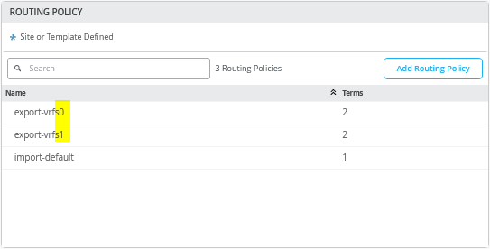 ではなく2つのエクスポートフィルター
見た目は同じかもしれませんが、「export-vrfs1」のすべてのステートメントには、 図40のように先頭にAP-Pathが設定されています。
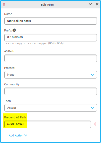 が含まれます
SRXクラスターとのBGPピアリングが確立されたら、以下の例に示すように、ファブリック内のASパスの先頭に付加されたSRXクラスターが表示されていることを確認します。まず、ファブリックのサービスブロック機能(ここではcore1-switch)の設定を確認します。
root@core1> show configuration | display set | match export-vrf
set groups top policy-options policy-statement export-vrfs0 term 01_fabric-all-no-hosts from route-filter-list 0-0-0-0_0-30
set groups top policy-options policy-statement export-vrfs0 term 01_fabric-all-no-hosts then accept
set groups top policy-options policy-statement export-vrfs0 term 02_overlaylo0 from route-filter-list 172-16-192-0_24-32
set groups top policy-options policy-statement export-vrfs0 term 02_overlaylo0 then accept
set groups top policy-options policy-statement export-vrfs1 term 01_fabric-all-no-hosts from route-filter-list 0-0-0-0_0-30
set groups top policy-options policy-statement export-vrfs1 term 01_fabric-all-no-hosts then as-path-prepend "64998 64998"
set groups top policy-options policy-statement export-vrfs1 term 01_fabric-all-no-hosts then accept
set groups top policy-options policy-statement export-vrfs1 term 02_overlaylo0 from route-filter-list 172-16-192-0_24-32
set groups top policy-options policy-statement export-vrfs1 term 02_overlaylo0 then as-path-prepend "64998 64998"
set groups top policy-options policy-statement export-vrfs1 term 02_overlaylo0 then accept
set groups top routing-instances devices protocols bgp group devices0 export export-vrfs0
set groups top routing-instances devices protocols bgp group devices1 export export-vrfs1
set groups top routing-instances customerb protocols bgp group customerb0 export export-vrfs0
set groups top routing-instances customerb protocols bgp group customerb1 export export-vrfs1
set groups top routing-instances customera protocols bgp group customera0 export export-vrfs0
set groups top routing-instances customera protocols bgp group customera1 export export-vrfs1
次に、以下の例のように、SRXクラスター上の設定に従ってルートを受信することも確認します。
# neighbor-IP:10.255.224.1 which is assigned on srx-cluster to vrf:customera interface ge-0/0/2.1091
root@srx1> show route receive-protocol bgp 10.255.224.1
.
public-int.inet.0: 46 destinations, 101 routes (46 active, 0 holddown, 0 hidden)
  Prefix                  Nexthop              MED     Lclpref    AS path
* 10.99.91.0/24           10.255.224.1                            64911 65002 65004 65005 I
* 10.99.99.0/24           10.255.224.1                            64911 65002 65004 65005 I
* 172.16.192.1/32         10.255.224.1                            64911 65002 65004 65005 I
* 172.16.192.4/32         10.255.224.1                            64911 65002 65004 65006 I
* 172.16.192.7/32         10.255.224.1                            64911 I
  172.16.192.10/32        10.255.224.1                            64911 65002 65004 65001 I
.
# neighbor-IP:10.255.226.1 which is assigned on srx-cluster to vrf:customera interface ge-0/0/3.1091
root@srx1> show route receive-protocol bgp 10.255.226.1
.
public-int.inet.0: 46 destinations, 101 routes (46 active, 0 holddown, 0 hidden)
  Prefix                  Nexthop              MED     Lclpref    AS path
  10.99.91.0/24           10.255.226.1                            64911 65001 65004 65005 I
  10.99.99.0/24           10.255.226.1                            64911 65001 65004 65005 I
  172.16.192.1/32         10.255.226.1                            64911 65001 65004 65005 I
  172.16.192.4/32         10.255.226.1                            64911 65001 65004 65006 I
  172.16.192.7/32         10.255.226.1                            64911 65001 65004 65002 I
* 172.16.192.10/32        10.255.226.1                            64911 I
.
# neighbor-IP:10.255.225.1 which is assigned on srx-cluster to vrf:customera interface ge-7/0/2.1099
root@srx1> show route receive-protocol bgp 10.255.225.1
.
public-int.inet.0: 46 destinations, 101 routes (46 active, 0 holddown, 0 hidden)
  Prefix                  Nexthop              MED     Lclpref    AS path
  10.99.91.0/24           10.255.225.1                            64998 64998 64911 65002 65004 65005 I
  10.99.99.0/24           10.255.225.1                            64998 64998 64911 65002 65004 65005 I
  172.16.192.1/32         10.255.225.1                            64998 64998 64911 65002 65004 65005 I
  172.16.192.4/32         10.255.225.1                            64998 64998 64911 65002 65004 65006 I
  172.16.192.7/32         10.255.225.1                            64998 64998 64911 I
  172.16.192.10/32        10.255.225.1                            64998 64998 64911 65002 65004 65001 I
.
# neighbor-IP:10.255.227.1 which is assigned on srx-cluster to vrf:customera interface ge-7/0/3.1099
root@srx1> show route receive-protocol bgp 10.255.227.1
.
public-int.inet.0: 46 destinations, 101 routes (46 active, 0 holddown, 0 hidden)
  Prefix                  Nexthop              MED     Lclpref    AS path
  10.99.91.0/24           10.255.227.1                            64998 64998 64911 65001 65004 65005 I
  10.99.99.0/24           10.255.227.1                            64998 64998 64911 65001 65004 65005 I
  172.16.192.1/32         10.255.227.1                            64998 64998 64911 65001 65004 65005 I
  172.16.192.4/32         10.255.227.1                            64998 64998 64911 65001 65004 65006 I
  172.16.192.7/32         10.255.227.1                            64998 64998 64911 65001 65004 65002 I
  172.16.192.10/32        10.255.227.1                            64998 64998 64911 I
表2は、サービスブロック機能としてのコア1スイッチとコア2スイッチの設定情報と、SRXクラスターのWANルーターの設定を示しています。 表1 (MX WANルーター用の場合)に関して変更点をマークしています。
| スイッチ | スイッチAS | VRF | コアP2P IP | コアIF | WANルーター | WANルーターP2P IP | WANルーターAS | WANルーターのIF | VLAN ID |
|---|---|---|---|---|---|---|---|---|---|
| コア1 | 64911 | カスタマーA | 10.255.224.1/31 | ge-0/0/5.1091 | ノード0 | 10.255.224.0/31 | 64901 | ge-0/0/2.1091 | 1091 |
| コア1 | 64911 | カスタマーB | 10.255.224.3/31 | ge-0/0/5.1081 | ノード0 | 10.255.224.2/31 | 64901 | ge-0/0/2.1081 | 1081 |
| コア1 | 64911 | デバイス | 10.255.224.5/31 | ge-0/0/5.1031 | ノード0 | 10.255.224.4/31 | 64901 | ge-0/0/2.1031 | 1031 |
| コア1 | 64911 | カスタマーA | 10.255.225.1/31 | ge-0/0/6.1099 | ノード1 | 10.255.225.0/31 | 64901 | ge-7/0/2.1099 | 1099 |
| コア1 | 64911 | カスタマーB | 10.255.225.3/31 | ge-0/0/6.1088 | ノード1 | 10.255.225.2/31 | 64901 | ge-7/0/2.1088 | 1088 |
| コア1 | 64911 | デバイス | 10.255.225.5/31 | ge-0/0/6.1033 | ノード1 | 10.255.225.4/31 | 64901 | ge-7/0/2.1033 | 1033 |
| コア2 | 64911 | カスタマーA | 10.255.226.1/31 | ge-0/0/5.1091 | ノード0 | 10.255.226.0/31 | 64901 | ge-0/0/3.1091 | 1091 |
| コア2 | 64911 | カスタマーB | 10.255.226.3/31 | ge-0/0/5.1081 | ノード0 | 10.255.226.2/31 | 64901 | ge-0/0/3.1081 | 1081 |
| コア2 | 64911 | デバイス | 10.255.226.5/31 | ge-0/0/5.1031 | ノード0 | 10.255.226.4/31 | 64901 | ge-0/0/3.1031 | 1031 |
| コア2 | 64911 | カスタマーA | 10.255.227.1/31 | ge-0/0/6.1099 | ノード1 | 10.255.227.0/31 | 64901 | ge-7/0/3.1099 | 1099 |
| コア2 | 64911 | カスタマーB | 10.255.227.3/31 | ge-0/0/6.1088 | ノード1 | 10.255.227.2/31 | 64901 | ge-7/0/3.1088 | 1088 |
| コア2 | 64911 | デバイス | 10.255.227.5/31 | ge-0/0/6.1033 | ノード1 | 10.255.227.4/31 | 64901 | ge-7/0/3.1033 | 1033 |
以下の擬似コードは、この例で core1 スイッチで設定する必要がある内容を説明しています。
# configure the Additional IP-Subnet 10.255.224.1 255.255.255.254 to Network/VLAN:vlan1091
# configure the Additional IP-Subnet 10.255.224.3 255.255.255.254 to Network/VLAN:vlan1081
# configure the Additional IP-Subnet 10.255.224.5 255.255.255.254 to Network/VLAN:vlan1031
# Then bind these 3 Network/VLANs to Port Interface ge-0/0/5 as L3-Sub-Interfaces with MTU=9018
#
# configure the Additional IP-Subnet 10.255.225.1 255.255.255.254 to Network/VLAN:vlan1099
# configure the Additional IP-Subnet 10.255.225.3 255.255.255.254 to Network/VLAN:vlan1088
# configure the Additional IP-Subnet 10.255.225.5 255.255.255.254 to Network/VLAN:vlan1033
# Then bind these 3 Network/VLANs to Port Interface ge-0/0/6 as L3-Sub-Interfaces with MTU=9018
#
# Enable BGP
# Create an Export policy called 'export-vrfs0'
# Add to this export Policy the following Networks as:
# - Add Term w. Name=fabric-all-no-hosts  Prefix=0.0.0.0/0-30  Protocol=None  Then=Accept
# - Add Term w. Name=overlaylo0 Prefix=172.16.192.0/24-32  Protocol=None  Then=Accept
#
# Create an Export policy called 'export-vrfs1'
# Add to this export Policy the following Networks as:
# - Add Term w. Name=fabric-all-no-hosts  Prefix=0.0.0.0/0-30  Protocol=None  Then=Accept  Add Action->Prepend AS Path='64998 64998'
# - Add Term w. Name=overlaylo0 Prefix=172.16.192.0/24-32  Protocol=None  Then=Accept  Add Action->Prepend AS Path='64998 64998'
#
# Create an Export policy called 'import-default'
# - Name=default  Prefix=0.0.0.0/0  Protocol=BGP  Action=Accept
#
# Create a BGP Group with:
# - Name=customera0
# - Type=External
# - Network (VLAN)=vlan1091
# - BFD interval=1000
# - Local AS=64911
# - Hold Time=90
# - Set Export=export-vrfs0 and Import=import-default
# Add also the following Neighbor
# - IP_Address=10.255.224.0  Neighbor_AS=64901  Hold-Time=90
#
# Create a BGP Group with:
# - Name=customerb0
# - Type=External
# - Network (VLAN)=vlan1081
# - BFD interval=1000
# - Local AS=64911
# - Hold Time=90
# - Set Export=export-vrfs0 and Import=import-default
# Add also the following Neighbor
# - IP_Address=10.255.224.2  Neighbor_AS=64901  Hold-Time=90
#
# Create a BGP Group with:
# - Name=devices0
# - Type=External
# - Network (VLAN)=vlan1031
# - BFD interval=1000
# - Local AS=64911
# - Hold Time=90
# - Set Export=export-vrfs0 and Import=import-default
# Add also the following Neighbor
# - IP_Address=10.255.224.4  Neighbor_AS=64901  Hold-Time=90
#
# Create a BGP Group with:
# - Name=customera1
# - Type=External
# - Network (VLAN)=vlan1099
# - BFD interval=1000
# - Local AS=64911
# - Hold Time=90
# - Set Export=export-vrfs1 and Import=import-default
# Add also the following Neighbor
# - IP_Address=10.255.225.0  Neighbor_AS=64901  Hold-Time=90
#
# Create a BGP Group with:
# - Name=customerb1
# - Type=External
# - Network (VLAN)=vlan1088
# - BFD interval=1000
# - Local AS=64911
# - Hold Time=90
# - Set Export=export-vrfs1 and Import=import-default
# Add also the following Neighbor
# - IP_Address=10.255.225.2  Neighbor_AS=64901  Hold-Time=90
#
# Create a BGP Group with:
# - Name=devices1
# - Type=External
# - Network (VLAN)=vlan1033
# - BFD interval=1000
# - Local AS=64911
# - Hold Time=90
# - Set Export=export-vrfs1 and Import=import-default
# Add also the following Neighbor
# - IP_Address=10.255.225.4  Neighbor_AS=64901  Hold-Time=90
以下の擬似コードは、この例で core2 スイッチで設定する必要がある内容を説明しています。
# configure the Additional IP-Subnet 10.255.226.1 255.255.255.254 to Network/VLAN:vlan1091
# configure the Additional IP-Subnet 10.255.226.3 255.255.255.254 to Network/VLAN:vlan1081
# configure the Additional IP-Subnet 10.255.226.5 255.255.255.254 to Network/VLAN:vlan1031
# Then bind these 3 Network/VLANs to Port Interface ge-0/0/5 as L3-Sub-Interfaces with MTU=9018
#
# configure the Additional IP-Subnet 10.255.227.1 255.255.255.254 to Network/VLAN:vlan1099
# configure the Additional IP-Subnet 10.255.227.3 255.255.255.254 to Network/VLAN:vlan1088
# configure the Additional IP-Subnet 10.255.227.5 255.255.255.254 to Network/VLAN:vlan1033
# Then bind these 3 Network/VLANs to Port Interface ge-0/0/6 as L3-Sub-Interfaces with MTU=9018
#
# Enable BGP
# Create an Export policy called 'export-vrfs0'
# Add to this export Policy the following Networks as:
# - Add Term w. Name=fabric-all-no-hosts  Prefix=0.0.0.0/0-30  Protocol=None  Then=Accept
# - Add Term w. Name=overlaylo0 Prefix=172.16.192.0/24-32  Protocol=None  Then=Accept
#
# Create an Export policy called 'export-vrfs1'
# Add to this export Policy the following Networks as:
# - Add Term w. Name=fabric-all-no-hosts  Prefix=0.0.0.0/0-30  Protocol=None  Then=Accept  Add Action->Prepend AS Path='64998 64998'
# - Add Term w. Name=overlaylo0 Prefix=172.16.192.0/24-32  Protocol=None  Then=Accept  Add Action->Prepend AS Path='64998 64998'
#
# Create an Export policy called 'import-default'
# - Name=default  Prefix=0.0.0.0/0  Protocol=BGP  Action=Accept
#
# Create a BGP Group with:
# - Name=customera0
# - Type=External
# - Network (VLAN)=vlan1091
# - BFD interval=1000
# - Local AS=64911
# - Hold Time=90
# - Set Export=export-vrfs0 and Import=import-default
# Add also the following Neighbor
# - IP_Address=10.255.226.0  Neighbor_AS=64901  Hold-Time=90
#
# Create a BGP Group with:
# - Name=customerb0
# - Type=External
# - Network (VLAN)=vlan1081
# - BFD interval=1000
# - Local AS=64911
# - Hold Time=90
# - Set Export=export-vrfs0 and Import=import-default
# Add also the following Neighbor
# - IP_Address=10.255.226.2  Neighbor_AS=64901  Hold-Time=90
#
# Create a BGP Group with:
# - Name=devices0
# - Type=External
# - Network (VLAN)=vlan1031
# - BFD interval=1000
# - Local AS=64911
# - Hold Time=90
# - Set Export=export-vrfs0 and Import=import-default
# Add also the following Neighbor
# - IP_Address=10.255.226.4  Neighbor_AS=64901  Hold-Time=90
#
# Create a BGP Group with:
# - Name=customera1
# - Type=External
# - Network (VLAN)=vlan1099
# - BFD interval=1000
# - Local AS=64911
# - Hold Time=90
# - Set Export=export-vrfs1 and Import=import-default
# Add also the following Neighbor
# - IP_Address=10.255.227.0  Neighbor_AS=64901  Hold-Time=90
#
# Create a BGP Group with:
# - Name=customerb1
# - Type=External
# - Network (VLAN)=vlan1088
# - BFD interval=1000
# - Local AS=64911
# - Hold Time=90
# - Set Export=export-vrfs1 and Import=import-default
# Add also the following Neighbor
# - IP_Address=10.255.227.2  Neighbor_AS=64901  Hold-Time=90
#
# Create a BGP Group with:
# - Name=devices1
# - Type=External
# - Network (VLAN)=vlan1033
# - BFD interval=1000
# - Local AS=64911
# - Hold Time=90
# - Set Export=export-vrfs1 and Import=import-default
# Add also the following Neighbor
# - IP_Address=10.255.227.4  Neighbor_AS=64901  Hold-Time=90
個々のサービスブロック機能(ここではcore1スイッチとcore2スイッチ)の設定が完了すると、概要表は図41のようになります。
図41は、コア1スイッチとコア2スイッチの個々のサービスブロック機能を設定した後のBGPがどのように見えるかの概要を示しています。
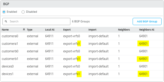 としたBGP設定の概要
次のJunos OS CLIは、この例でシリーズファイアウォールクラスターに必要な設定全体を表しています。
set groups node0 system host-name srx1_node0
set groups node1 system host-name srx2_node1
set apply-groups ""
set chassis aggregated-devices ethernet device-count 10
set chassis cluster control-link-recovery
set chassis cluster reth-count 5
set chassis cluster initial-hold 60
set chassis cluster redundancy-group 1 node 0 priority 200
set chassis cluster redundancy-group 1 node 1 priority 100
set chassis cluster redundancy-group 1 gratuitous-arp-count 4
# Interface monitoring turned OFF for vSRX
# set chassis cluster redundancy-group 1 interface-monitor ge-0/0/2 weight 255
# set chassis cluster redundancy-group 1 interface-monitor ge-0/0/3 weight 255
# set chassis cluster redundancy-group 1 interface-monitor ge-7/0/2 weight 255
# set chassis cluster redundancy-group 1 interface-monitor ge-7/0/3 weight 255
set interfaces fab0 fabric-options member-interfaces ge-0/0/0
set interfaces fab1 fabric-options member-interfaces ge-7/0/0
#
# rebuild trust zone to clear old interfaces bound
delete security zones security-zone trust
set security zones security-zone trust tcp-rst
set security zones security-zone trust host-inbound-traffic system-services all
set security zones security-zone trust host-inbound-traffic protocols all
#
delete interfaces ge-0/0/2
set interfaces ge-0/0/2 flexible-vlan-tagging
set interfaces ge-0/0/2 mtu 9018
set interfaces ge-0/0/2 unit 1091 description vlan1091
set interfaces ge-0/0/2 unit 1091 vlan-id 1091
set interfaces ge-0/0/2 unit 1091 family inet address 10.255.224.0/31
set security zones security-zone trust interfaces ge-0/0/2.1091 host-inbound-traffic protocols bgp
set security zones security-zone trust interfaces ge-0/0/2.1091 host-inbound-traffic system-services ping
set interfaces ge-0/0/2 unit 1081 description vlan1081
set interfaces ge-0/0/2 unit 1081 vlan-id 1081
set interfaces ge-0/0/2 unit 1081 family inet address 10.255.224.2/31
set security zones security-zone trust interfaces ge-0/0/2.1081 host-inbound-traffic protocols bgp
set security zones security-zone trust interfaces ge-0/0/2.1081 host-inbound-traffic system-services ping
set interfaces ge-0/0/2 unit 1031 description vlan1031
set interfaces ge-0/0/2 unit 1031 vlan-id 1031
set interfaces ge-0/0/2 unit 1031 family inet address 10.255.224.4/31
set security zones security-zone trust interfaces ge-0/0/2.1031 host-inbound-traffic protocols bgp
set security zones security-zone trust interfaces ge-0/0/2.1031 host-inbound-traffic system-services ping
#
delete interfaces ge-0/0/3
set interfaces ge-0/0/3 flexible-vlan-tagging
set interfaces ge-0/0/3 mtu 9018
set interfaces ge-0/0/3 unit 1091 description vlan1091
set interfaces ge-0/0/3 unit 1091 vlan-id 1091
set interfaces ge-0/0/3 unit 1091 family inet address 10.255.226.0/31
set security zones security-zone trust interfaces ge-0/0/3.1091 host-inbound-traffic protocols bgp
set security zones security-zone trust interfaces ge-0/0/3.1091 host-inbound-traffic system-services ping
set interfaces ge-0/0/3 unit 1081 description vlan1081
set interfaces ge-0/0/3 unit 1081 vlan-id 1081
set interfaces ge-0/0/3 unit 1081 family inet address 10.255.226.2/31
set security zones security-zone trust interfaces ge-0/0/3.1081 host-inbound-traffic protocols bgp
set security zones security-zone trust interfaces ge-0/0/3.1081 host-inbound-traffic system-services ping
set interfaces ge-0/0/3 unit 1031 description vlan1031
set interfaces ge-0/0/3 unit 1031 vlan-id 1031
set interfaces ge-0/0/3 unit 1031 family inet address 10.255.226.4/31
set security zones security-zone trust interfaces ge-0/0/3.1031 host-inbound-traffic protocols bgp
set security zones security-zone trust interfaces ge-0/0/3.1031 host-inbound-traffic system-services ping
#
delete interfaces ge-7/0/2
set interfaces ge-7/0/2 flexible-vlan-tagging
set interfaces ge-7/0/2 mtu 9018
set interfaces ge-7/0/2 unit 1099 description vlan1099
set interfaces ge-7/0/2 unit 1099 vlan-id 1099
set interfaces ge-7/0/2 unit 1099 family inet address 10.255.225.0/31
set security zones security-zone trust interfaces ge-7/0/2.1099 host-inbound-traffic protocols bgp
set security zones security-zone trust interfaces ge-7/0/2.1099 host-inbound-traffic system-services ping
set interfaces ge-7/0/2 unit 1088 description vlan1088
set interfaces ge-7/0/2 unit 1088 vlan-id 1088
set interfaces ge-7/0/2 unit 1088 family inet address 10.255.225.2/31
set security zones security-zone trust interfaces ge-7/0/2.1088 host-inbound-traffic protocols bgp
set security zones security-zone trust interfaces ge-7/0/2.1088 host-inbound-traffic system-services ping
set interfaces ge-7/0/2 unit 1033 description vlan1033
set interfaces ge-7/0/2 unit 1033 vlan-id 1033
set interfaces ge-7/0/2 unit 1033 family inet address 10.255.225.4/31
set security zones security-zone trust interfaces ge-7/0/2.1033 host-inbound-traffic protocols bgp
set security zones security-zone trust interfaces ge-7/0/2.1033 host-inbound-traffic system-services ping
#
delete interfaces ge-7/0/3
set interfaces ge-7/0/3 flexible-vlan-tagging
set interfaces ge-7/0/3 mtu 9018
set interfaces ge-7/0/3 unit 1099 description vlan1099
set interfaces ge-7/0/3 unit 1099 vlan-id 1099
set interfaces ge-7/0/3 unit 1099 family inet address 10.255.227.0/31
set security zones security-zone trust interfaces ge-7/0/3.1099 host-inbound-traffic protocols bgp
set security zones security-zone trust interfaces ge-7/0/3.1099 host-inbound-traffic system-services ping
set interfaces ge-7/0/3 unit 1088 description vlan1088
set interfaces ge-7/0/3 unit 1088 vlan-id 1088
set interfaces ge-7/0/3 unit 1088 family inet address 10.255.227.2/31
set security zones security-zone trust interfaces ge-7/0/3.1088 host-inbound-traffic protocols bgp
set security zones security-zone trust interfaces ge-7/0/3.1088 host-inbound-traffic system-services ping
set interfaces ge-7/0/3 unit 1033 description vlan1033
set interfaces ge-7/0/3 unit 1033 vlan-id 1033
set interfaces ge-7/0/3 unit 1033 family inet address 10.255.227.4/31
set security zones security-zone trust interfaces ge-7/0/3.1033 host-inbound-traffic protocols bgp
set security zones security-zone trust interfaces ge-7/0/3.1033 host-inbound-traffic system-services ping
#
# needed in and export policy
delete policy-options
set policy-options policy-statement fabric term 1 from protocol bgp
set policy-options policy-statement fabric term 1 from route-filter 0.0.0.0/0 orlonger
set policy-options policy-statement fabric term 1 then accept
set policy-options policy-statement fabric term 2 then reject
set policy-options policy-statement internet0 term 1 from protocol static
set policy-options policy-statement internet0 term 1 from route-filter 0.0.0.0/0 exact
set policy-options policy-statement internet0 term 1 then accept
set policy-options policy-statement internet0 term 2 then reject
set policy-options policy-statement internet1 term 1 from protocol static
set policy-options policy-statement internet1 term 1 from route-filter 0.0.0.0/0 exact
set policy-options policy-statement internet1 term 1 then as-path-prepend "64999 64999"
set policy-options policy-statement internet1 term 1 then accept
set policy-options policy-statement internet1 term 2 then reject
#
delete routing-instances public-int
set routing-instances public-int instance-type virtual-router
set routing-instances public-int interface ge-0/0/2.1091
set routing-instances public-int interface ge-0/0/2.1081
set routing-instances public-int interface ge-0/0/2.1031
set routing-instances public-int interface ge-0/0/3.1091
set routing-instances public-int interface ge-0/0/3.1081
set routing-instances public-int interface ge-0/0/3.1031
set routing-instances public-int interface ge-7/0/2.1099
set routing-instances public-int interface ge-7/0/2.1088
set routing-instances public-int interface ge-7/0/2.1033
set routing-instances public-int interface ge-7/0/3.1099
set routing-instances public-int interface ge-7/0/3.1088
set routing-instances public-int interface ge-7/0/3.1033
#
delete routing-instances public-int protocols bgp group customera
delete routing-instances public-int protocols bgp group customera0
set routing-instances public-int protocols bgp group customera0 type external
set routing-instances public-int protocols bgp group customera0 family inet unicast
set routing-instances public-int protocols bgp group customera0 multipath multiple-as
set routing-instances public-int protocols bgp group customera0 local-as 64901
set routing-instances public-int protocols bgp group customera0 hold-time 90
set routing-instances public-int protocols bgp group customera0 import fabric
set routing-instances public-int protocols bgp group customera0 export internet0
set routing-instances public-int protocols bgp group customera0 bfd-liveness-detection minimum-interval 1000
set routing-instances public-int protocols bgp group customera0 bfd-liveness-detection multiplier 3
set routing-instances public-int protocols bgp group customera0 bfd-liveness-detection session-mode automatic
set routing-instances public-int protocols bgp group customera0 neighbor 10.255.224.1 peer-as 64911
set routing-instances public-int protocols bgp group customera0 neighbor 10.255.226.1 peer-as 64911
#
delete routing-instances public-int protocols bgp group customera1
set routing-instances public-int protocols bgp group customera1 type external
set routing-instances public-int protocols bgp group customera1 family inet unicast
set routing-instances public-int protocols bgp group customera1 multipath multiple-as
set routing-instances public-int protocols bgp group customera1 local-as 64901
set routing-instances public-int protocols bgp group customera1 hold-time 90
set routing-instances public-int protocols bgp group customera1 import fabric
set routing-instances public-int protocols bgp group customera1 export internet1
set routing-instances public-int protocols bgp group customera1 bfd-liveness-detection minimum-interval 1000
set routing-instances public-int protocols bgp group customera1 bfd-liveness-detection multiplier 3
set routing-instances public-int protocols bgp group customera1 bfd-liveness-detection session-mode automatic
set routing-instances public-int protocols bgp group customera1 neighbor 10.255.225.1 peer-as 64911
set routing-instances public-int protocols bgp group customera1 neighbor 10.255.227.1 peer-as 64911
#
delete routing-instances public-int protocols bgp group customerb
delete routing-instances public-int protocols bgp group customerb0
set routing-instances public-int protocols bgp group customerb0 type external
set routing-instances public-int protocols bgp group customerb0 family inet unicast
set routing-instances public-int protocols bgp group customerb0 multipath multiple-as
set routing-instances public-int protocols bgp group customerb0 local-as 64901
set routing-instances public-int protocols bgp group customerb0 hold-time 90
set routing-instances public-int protocols bgp group customerb0 import fabric
set routing-instances public-int protocols bgp group customerb0 export internet0
set routing-instances public-int protocols bgp group customerb0 bfd-liveness-detection minimum-interval 1000
set routing-instances public-int protocols bgp group customerb0 bfd-liveness-detection multiplier 3
set routing-instances public-int protocols bgp group customerb0 bfd-liveness-detection session-mode automatic
set routing-instances public-int protocols bgp group customerb0 neighbor 10.255.224.3 peer-as 64911
set routing-instances public-int protocols bgp group customerb0 neighbor 10.255.226.3 peer-as 64911
#
delete routing-instances public-int protocols bgp group customerb1
set routing-instances public-int protocols bgp group customerb1 type external
set routing-instances public-int protocols bgp group customerb1 family inet unicast
set routing-instances public-int protocols bgp group customerb1 multipath multiple-as
set routing-instances public-int protocols bgp group customerb1 local-as 64901
set routing-instances public-int protocols bgp group customerb1 hold-time 90
set routing-instances public-int protocols bgp group customerb1 import fabric
set routing-instances public-int protocols bgp group customerb1 export internet1
set routing-instances public-int protocols bgp group customerb1 bfd-liveness-detection minimum-interval 1000
set routing-instances public-int protocols bgp group customerb1 bfd-liveness-detection multiplier 3
set routing-instances public-int protocols bgp group customerb1 bfd-liveness-detection session-mode automatic
set routing-instances public-int protocols bgp group customerb1 neighbor 10.255.225.3 peer-as 64911
set routing-instances public-int protocols bgp group customerb1 neighbor 10.255.227.3 peer-as 64911
#
delete routing-instances public-int protocols bgp group devices
delete routing-instances public-int protocols bgp group devices0
set routing-instances public-int protocols bgp group devices0 type external
set routing-instances public-int protocols bgp group devices0 family inet unicast
set routing-instances public-int protocols bgp group devices0 multipath multiple-as
set routing-instances public-int protocols bgp group devices0 local-as 64901
set routing-instances public-int protocols bgp group devices0 hold-time 90
set routing-instances public-int protocols bgp group devices0 import fabric
set routing-instances public-int protocols bgp group devices0 export internet0
set routing-instances public-int protocols bgp group devices0 bfd-liveness-detection minimum-interval 1000
set routing-instances public-int protocols bgp group devices0 bfd-liveness-detection multiplier 3
set routing-instances public-int protocols bgp group devices0 bfd-liveness-detection session-mode automatic
set routing-instances public-int protocols bgp group devices0 neighbor 10.255.224.5 peer-as 64911
set routing-instances public-int protocols bgp group devices0 neighbor 10.255.226.5 peer-as 64911
#
delete routing-instances public-int protocols bgp group devices1
set routing-instances public-int protocols bgp group devices1 type external
set routing-instances public-int protocols bgp group devices1 family inet unicast
set routing-instances public-int protocols bgp group devices1 multipath multiple-as
set routing-instances public-int protocols bgp group devices1 local-as 64901
set routing-instances public-int protocols bgp group devices1 hold-time 90
set routing-instances public-int protocols bgp group devices1 import fabric
set routing-instances public-int protocols bgp group devices1 export internet1
set routing-instances public-int protocols bgp group devices1 bfd-liveness-detection minimum-interval 1000
set routing-instances public-int protocols bgp group devices1 bfd-liveness-detection multiplier 3
set routing-instances public-int protocols bgp group devices1 bfd-liveness-detection session-mode automatic
set routing-instances public-int protocols bgp group devices1 neighbor 10.255.225.5 peer-as 64911
set routing-instances public-int protocols bgp group devices1 neighbor 10.255.227.5 peer-as 64911