レイヤー3VPNパフォーマンスの向上
このトピックでは、連鎖された複合ネクストホップ(CNH)を紹介し、バックツーバックの PE ルーターで連鎖された CNH を有効にする方法の例を示します。
VPNおよびレイヤー2回線向けの連鎖された複合ネクストホップ
ジュニパーネットワークスのPTXシリーズパケットトランスポートルーター、MICおよびMPCインターフェイスを搭載したMXシリーズ5Gユニバーサルルーティングプラットフォーム、T4000コアルーターは、主に大規模ネットワークのコアで大量のトラフィックを処理するように設計されています。連鎖されたCNHは、ルーターがはるかに大量のルートを処理できるようにすることで、この機能を促進するのに役立ちます。連鎖されたCNHにより、ルーターは、各ルートに宛先も含めるのではなく、同じ宛先を共有するルートのセットを共通の転送ネクストホップに誘導することができます。ネットワークの宛先が変更された場合、その宛先を共有するすべてのルートを新しい情報で更新するのではなく、共有転送ネクストホップのみを新しい情報で更新します。連鎖されたCNHは、新しい宛先を含むこの転送ネクストホップを引き続き指し示します。
MPLS LSP のネクスト ホップがルーターで作成されると、最も内側の MPLS ラベルに対応するタグ情報が抽出されて、連鎖された CNH になります。連鎖されたCNHは、イングレスパケット転送エンジンに保存されます。連鎖されたCNHは、エグレスパケット転送エンジンに存在する転送ネクストホップと呼ばれるネクストホップを指しています。転送ネクストホップには、その他すべての情報(最も内側のラベルを除くすべてのラベルと、実際のネクストホップノードに対応する IFA/IP 情報)が含まれています。連鎖した多くの複合ネクストホップは、同じ転送ネクストホップを共有できます。さらに、最も内側のラベル(つまりVPNラベル)を転送ネクストホップから分離し、イングレスPFE(連鎖された複合ネクストホップ内)に保存することで、エグレスパケット転送エンジンに保存される書き換え文字列の数を減らすことで、エグレスパケット転送エンジンメモリを節約することができます。
表 1 は、MPLS ネットワーク上のイングレスルーターまたはトランジットルーターの連鎖された CNH のサポートを示しています。
プラットホーム |
L2 VPN |
L3 VPN |
L2 CKT |
|---|---|---|---|
PTXシリーズ |
イングレスとトランジット |
イングレスとトランジット |
イングレスのみ |
MXシリーズ |
イングレスのみ |
イングレスのみ |
イングレスのみ |
T4000ルーターで連鎖CNHを有効にするには、ネットワークサービスモードで enhanced-mode オプションを使用するようにシャーシを設定する必要があります。
連鎖されたコンポジットネクストホップのメリット
連鎖CNHは、転送テーブルのサイズを小さくすることで、ルーターのメモリとパフォーマンスを最適化します。ルーターは、ネクストホップが同じ場合、異なる宛先を持つルートに対して、転送テーブルの同じネクストホップエントリーを使用できます。これにより、転送テーブルのエントリー数が減り、ネクストホップエントリーを変更しなければならない場合の変更回数が減少します。
レイヤー 3 VPN で一意の内部 VPN ラベルを使用したルート更新の受け入れ
ジュニパーネットワークスのルーター上に設定されたレイヤー3 VPNの場合、Junos OSは通常、PE(プロバイダエッジ)ルーターのカスタマーエッジ(CE)に接続するVRF(仮想ルーティングおよび転送)インターフェイスごとに1つの内部VPNラベルを割り当てます。しかし、他のベンダーは、PEルーターのCE向けインターフェイスを介して学習した各ルートに1つのVPNラベルを割り当てています。この方法では、VPNラベルの数が指数関数的に増加し、システム処理が遅くなり、コンバージェンス時間が遅くなります。
連鎖CNHは、個々のネクストホップに関連する部分的な書き換え文字列を連結してより大きな書き換え文字列を形成し、パケットに追加される合成関数です。この機能を利用することで、ジュニパーネットワークスのルーターで処理できる固有の内部VPNラベルを持つルートの数が大幅に増加します。レイヤー3VPNに関連付けられた共通のルート更新要素が統合されるため、ジュニパーネットワークスのルーターが維持する必要があるルート更新の数と個々の状態が削減され、拡張性とコンバージェンスのパフォーマンスが向上します。
ACXシリーズ ルーターは、レイヤー 3 VPN に対してのみ、[edit routing-options forwarding-table] 階層レベルで chained-composite-next-hop ingress CLI ステートメントをサポートします。レイヤー2サービス向けのchained-composite-next-hop ingress CLIステートメントはサポートされていません。
管理するVPNラベルの数と、IPv6ラベル付きルート用に連鎖CNHを作成するかどうかに基づいて、ルーターを設定できます。
最大 100 万のレイヤー 3 VPN ルート更新に対応
最大 100 万個のレイヤー 3 VPN ラベルを持つ混合ベンダー ネットワークに参加しているジュニパーネットワークス ルーターの場合は、[edit routing-options forwarding-table chained-composite-next-hop ingress] 階層レベルで l3vpn ステートメントを含めます。l3vpnステートメントはデフォルトで無効になっています。
ACXシリーズルーターは、にある chained-composite-next-hop ingress CLIステートメントをサポートしていません。 [edit routing-options forwarding-table] hierarchy level.
レイヤー3VPNをサポートするために、最大100万ルートの混合ベンダーネットワークにジュニパーネットワークスルーターを導入している場合は、常に l3vpn ステートメントを設定することをお勧めします。
このステートメントを使用すると、ジュニパーネットワークスのルーターのみが展開されているネットワークでも、ジュニパーネットワークスルーターのレイヤー3 VPNのパフォーマンスを向上させることができるため、これらのネットワークでもステートメントを設定することをお勧めします。
以下のルーターで l3vpn ステートメントを設定できます。
ACXシリーズルーター
MXシリーズルーター
M120ルーター
1つ以上のEnhanced III FPCを搭載したM320ルーター
T Seriesルーター(Junos OS リリース10.4以降用)
一意の内部VPNラベルを持つ最大100万のレイヤー3 VPNルート更新を受け入れるには、 l3vpn ステートメントを設定します。このステートメントは、間接的に接続された PE ルーターでのみサポートされます。PEルーターに直接接続されたルーターでこのステートメントを設定しても、メリットはありません。直接接続されたPEルーターと間接的に接続されたPEルーターの両方へのリンクが混在するルーターで、 l3vpn ステートメントを設定できます。
vpn-unequal-cost ステートメントを設定したと同時に、l3vpn ステートメントとサブステートメントを設定することはできません。
一意の内部 VPN ラベルを持つ最大 100 万のレイヤー 3 VPN ルート更新を受け入れるようにルーターを構成するには:
l3vpn ステートメントを設定した後、以下のコマンドの表示出力を調べることで、レイヤー 3 VPN ルートが連鎖された CNH の一部であるかどうかを判断できます。
show route route-value extensiveshow route forwarding-table destination destination-value extensive
100万を超えるレイヤー3VPNルート更新の受け入れ
100万枚以上のレイヤー3 VPNラベルを持つ混合ベンダーネットワークに参加しているジュニパーネットワークスルーターの場合は、[edit routing-options forwarding-table chained-composite-next-hop ingress l3vpn]階層レベルでextended-spaceステートメントを含めます。extended-spaceステートメントはデフォルトで無効になっています。
chained-composite-next-hop ingressおよびextended-spaceステートメントは、ACXシリーズルーターではサポートされていません。
100 万ルート以上を含むベンダーが混在するネットワークでは、レイヤー 3 VPN をサポートするために extended-space ステートメントを設定することをお勧めします。
このステートメントを使用すると、ジュニパーネットワークスのルーターのみが展開されているネットワークでも、ジュニパーネットワークスルーターのレイヤー3 VPNのパフォーマンスを向上させることができるため、これらのネットワークでもステートメントを設定することをお勧めします。
extended-spaceステートメントを使用すると、ジュニパーネットワークスルーターで処理できる一意の内部VPNラベルを持つルートの数を2倍にすることができます。ただし、このような非常に大規模なレイヤー 3 VPN シナリオを構成する場合は、次のガイドラインを念頭に置いてください。
extended-spaceステートメントは、MPCのみを含むMXシリーズルーターでのみサポートされています。シャーシは、ネットワーク サービス モードで
enhanced-ipオプションを使用するように設定する必要があります。シャーシネットワークサービスの設定の詳細については、 Junos OS管理ライブラリを参照してください。
関連するポリシーに対して、パケットごとのロードバランシングを設定してください。
ポリシーの設定の詳細については 、「ルーティングポリシー、ファイアウォールフィルタ、およびトラフィックポリサーユーザーガイド」を参照してください。
64ビットJunos OSで動作する64ビットルーティングエンジンを使用して、固有の内部VPNラベルを持つレイヤー3 VPNプレフィックスをより高い規模でサポートすることを強くお勧めします。
一意の内部 VPN ラベルを持つレイヤー 3 VPN ルート更新を 100 万件を超えるレイヤー 3 VPN を受け入れるようにルーターを設定するには:
設定が完了したら、以下のコマンドの表示出力を調べることで、レイヤー3 VPNルートがCNHの一部であるかどうかを判断できます。
show route route-value extensiveshow route forwarding-table destination destination-value extensive
IPv6 ラベル付きユニキャストルートの連鎖された複合ネクストホップの有効化
ステートメントを labeled-bgp および inet6 設定することで、IPv6 ラベル付きユニキャストルートで連鎖された CNH を有効化できます。
[edit routing-options forwarding-table chained-composite-next-hop ingress labeled-bgp]階層レベルでinet6ステートメントを含めます。このステートメントはデフォルトで無効になっています。
例:VPN での直接 PE-PE 接続用の連鎖コンポジット ネクスト ホップの設定
この例では、MXシリーズおよびT4000ルーター上のMICおよびMPCインターフェイスの連鎖CNHを使用して、バックツーバックのPE(プロバイダエッジ)ルーターレイヤー3 VPN(仮想プライベートネットワーク)接続を有効にする方法を示しています。
必要条件
この例では、以下のハードウェアとソフトウェアのコンポーネントを使用しています。
-
MX240、MX480、MX960、または T4000 ルーターの組み合わせが可能な 6 台のルーター。
-
すべてのデバイスで実行されている Junos OS リリース 13.3。
開始する前に、以下を実行します。
-
デバイスインターフェイスを設定します。
-
すべてのルーターで以下のルーティングプロトコルを設定します。
-
MPLS
-
BGP
-
PE デバイス間のトンネルとしての LDP LSP
-
OSPF またはその他の IGP プロトコル
-
概要
Junos OS リリース 13.3 より前では、MPLS コアルーターが存在しない縮退したレイヤー 3 VPN のケースで、バックツーバックの PE-PE 接続で利用可能な外部ラベルがなく、イングレス PE デバイスが単一の VPN ラベルのみをプッシュするため、フラット化された間接ネクストホップとユニキャストネクストホップの以前の動作が利用されていました。PE-PE パスと PE-P-PE パスが混在するレイヤー 3 VPN マルチパス シナリオでは、連鎖された CNH も使用できませんでした。
MICおよびMPCインターフェイスのみをサポートするプラットフォームでは、連鎖CNHがデフォルトで有効になっています。DPCとMPCの両方のインターフェイスをサポートするプラットフォームでは、レイヤー3 vpn PE-PE接続用の連鎖CNHをサポートするために pe-pe-connection ステートメントを必要としました。ただし、 pe-pe-connection ステートメントは、MICおよびFPCインターフェイスのみを備えたプラットフォームではサポートされていませんでした。
これらの制限に対する解決策として、Junos OS リリース 13.3 以降、連鎖された CNH のサポートが強化され、ユーザーの設定に依存することなく、起動時に連鎖された CNH 上の基盤となるプラットフォーム機能を自動的に識別し、レイヤー 3 VPN ラベルに埋め込むネクストホップの種類(複合または間接)を決定できるようになりました。これにより、連鎖CNHを使用したレイヤー3 VPNにおけるバックツーバックのPE-PE接続のサポートが強化され、 pe-pe-connection ステートメントが不要になります。
直接接続されたPEデバイスで連鎖CNHを有効にするには、[edit routing-options forwarding-table chained-composite-next-hop ingress]階層レベルでl3vpnステートメントを含めることに加えて、以下の変更を行います。
-
DPCとMPC FPCの両方を含むMXシリーズ5Gユニバーサルルーティングプラットフォームでは、連鎖されたCNHはデフォルトで無効になっています。MX240、MX480、MX960で連鎖CNHを有効にするには、ネットワークサービスモードで
enhanced-ipオプションを使用するようにシャーシを設定する必要があります。 -
MPCおよびFPCを含むT4000コアルーターでは、連鎖されたCNHはデフォルトで無効になっています。T4000ルーターで連鎖CNHを有効にするには、ネットワークサービスモードで
enhanced-modeオプションを使用するようにシャーシを設定する必要があります。
位相幾何学
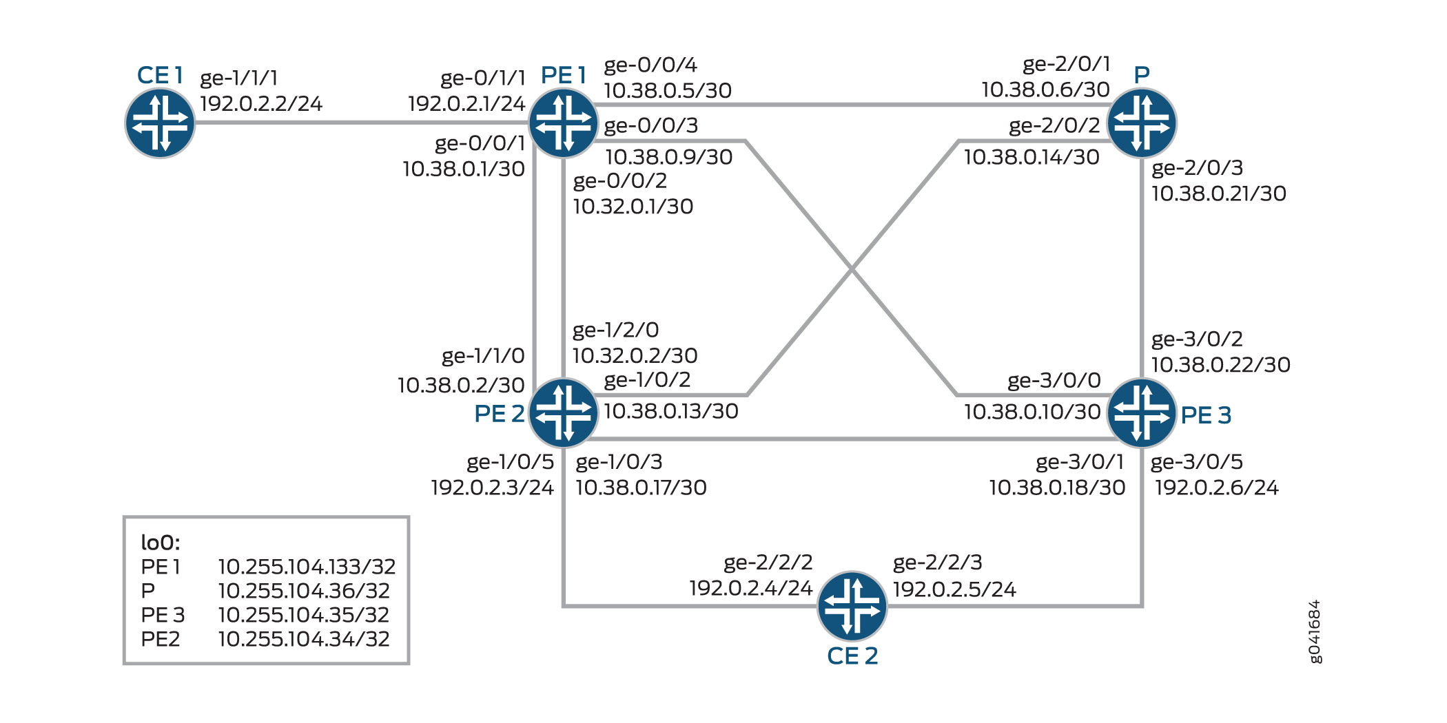
構成
CLIクイック構成
この例をすばやく設定するには、次のコマンドをコピーしてテキストファイルに貼り付け、改行を削除して、ネットワーク構成に合わせて必要な詳細を変更し、 [edit] 階層レベルのCLIにコマンドをコピー&ペーストしてください。
CE1の
               set interfaces ge-1/1/1 unit 0 family inet address 192.0.2.2/24

               set interfaces ge-1/1/1 unit 0 family iso

               set interfaces ge-1/1/1 unit 0 family mpls

               set interfaces lo0 unit 0 family inet address 198.51.100.1/24

               set protocols bgp group PE type external

               set protocols bgp group PE peer-as 200

               set protocols bgp group PE neighbor 192.0.2.1

               set routing-options autonomous-system 100
PE1
               set interfaces ge-0/0/1 unit 0 family inet address 10.38.0.1/30

               set interfaces ge-0/0/1 unit 0 family mpls

               set interfaces ge-0/0/2 unit 0 family inet address 10.38.0.5/30

               set interfaces ge-0/0/2 unit 0 family mpls

               set interfaces ge-0/0/3 unit 0 family inet address 10.38.0.9/30

               set interfaces ge-0/0/3 unit 0 family mpls

               set interfaces ge-0/0/4 unit 0 family inet address 10.32.0.1/30

               set interfaces ge-0/0/4 unit 0 family mpls

               set interfaces ge-0/1/1 unit 0 family inet address 192.0.2.1/24

               set interfaces ge-0/1/1 unit 0 family mpls

               set interfaces lo0 unit 0 family inet address 10.255.104.133/32

               set chassis network-services enhanced-ip

               set routing-options forwarding-table chained-composite-next-hop ingress l3vpn

               set routing-options autonomous-system 200

               set routing-options forwarding-table export lbpp

               set protocols mpls interface 10.38.0.1/30

               set protocols mpls interface 10.32.0.1/30

               set protocols mpls interface 10.38.0.5/30

               set protocols mpls interface 10.38.0.9/30

               set protocols bgp group PEs type internal

               set protocols bgp group PEs local-address 10.255.104.133

               set protocols bgp group PEs family inet unicast

               set protocols bgp group PEs family inet-vpn unicast

               set protocols bgp group PEs neighbor 10.255.104.134 local-preference 200

               set protocols bgp group PEs neighbor 10.255.104.135

               set protocols ospf area 0.0.0.0 interface all

               set protocols ospf area 0.0.0.0 interface fxp0.0 disable

               set protocols ospf area 0.0.0.0 interface lo0.0 passive

               set protocols ldp interface all

               set protocols ldp interface fxp0.0 disable

               set policy-options policy-statement lbpp then load-balance per-packet

               set routing-instances vpn-a instance-type vrf

               set routing-instances vpn-a interface ge-0/1/1.0

               set routing-instances vpn-a route-distinguisher 200:1

               set routing-instances vpn-a vrf-target target:200:1

               set routing-instances vpn-a vrf-table-label

               set routing-instances vpn-a protocols bgp group CE type external

               set routing-instances vpn-a protocols bgp group CE peer-as 100

               set routing-instances vpn-a protocols bgp group CE neighbor 192.0.2.2
PE2の
               set interfaces ge-1/0/2 unit 0 family inet address 10.38.0.13/30

               set interfaces ge-1/0/2 unit 0 family mpls

               set interfaces ge-1/0/3 unit 0 family inet address 10.32.0.17/30

               set interfaces ge-1/0/3 unit 0 family mpls

               set interfaces ge-1/0/5 unit 0 family inet address 192.0.2.3/24

               set interfaces ge-1/0/5 unit 0 family mpls

               set interfaces ge-1/1/0 unit 0 family inet address 10.38.0.2/30

               set interfaces ge-1/1/0 unit 0 family mpls

               set interfaces ge-1/2/0 unit 0 family inet address 10.32.0.2/30

               set interfaces ge-1/2/0 unit 0 family mpls

               set interfaces lo0 unit 0 family inet address 10.255.104.134/32

               set chassis network-services enhanced-ip

               set routing-options forwarding-table chained-composite-next-hop ingress l3vpn

               set routing-instances vpn-a instance-type vrf

               set routing-instances vpn-a interface ge-1/0/5.0

               set routing-instances vpn-a route-distinguisher 200:2

               set routing-instances vpn-a vrf-target target:200:1

               set routing-instances vpn-a protocols bgp group CE type external

               set routing-instances vpn-a protocols bgp group CE peer-as 300

               set routing-instances vpn-a protocols bgp group CE neighbor 192.0.2.3

               set protocols mpls interface 10.38.0.2/30

               set protocols mpls interface 10.32.0.2/30

               set protocols mpls interface 10.38.0.13/30

               set protocols mpls interface 10.38.0.17/30

               set protocols bgp group PEs type internal

               set protocols bgp group PEs local-address 10.255.104.134

               set protocols bgp group PEs family inet unicast

               set protocols bgp group PEs family inet-vpn unicast

               set protocols bgp group PEs neighbor 10.255.104.133

               set protocols bgp group PEs neighbor 10.255.104.135

               set protocols ospf area 0.0.0.0 interface all

               set protocols ospf area 0.0.0.0 interface fxp0.0 disable

               set protocols ospf area 0.0.0.0 interface lo0.0 passive

               set protocols ldp interface all

               set protocols ldp interface fxp0.0 disable

               set routing-options autonomous-system 200
Pの
               set interfaces ge-2/0/1 unit 0 family inet address 10.38.0.6/30

               set interfaces ge-2/0/1 unit 0 family mpls

               set interfaces ge-2/0/2 unit 0 family inet address 10.38.0.14/30

               set interfaces ge-2/0/2 unit 0 family mpls

               set interfaces ge-2/0/3 unit 0 family inet address 10.38.0.21/30

               set interfaces ge-2/0/3 unit 0 family mpls

               set interfaces lo0 unit 0 family inet address 10.255.104.136/32

               set protocols mpls interface 10.38.0.6/30

               set protocols mpls interface 10.38.0.14/30

               set protocols mpls interface 10.38.0.21/30

               set protocols bgp group PEs type internal

               set protocols bgp group PEs local-address 10.255.104.136

               set protocols bgp group PEs family inet unicast

               set protocols bgp group PEs family inet-vpn unicast

               set protocols bgp group PEs neighbor 10.255.104.133

               set protocols ospf area 0.0.0.0 interface all

               set protocols ospf area 0.0.0.0 interface fxp0.0 disable

               set protocols ospf area 0.0.0.0 interface lo0.0 passive

               set protocols ldp interface all

               set protocols ldp interface fxp0.0 disable

               set routing-options autonomous-system 200
PE3の
               set interfaces ge-3/0/0 unit 0 family inet address 10.38.0.10/30r0-r3
set interfaces ge-3/0/0 unit 0 family mpls

               set interfaces ge-3/0/1 unit 0 family inet address 10.38.0.18/30r0-r1-2
set interfaces ge-3/0/1 unit 0 family mpls

               set interfaces ge-3/0/2 unit 0 family inet address 10.38.0.22/30

               set interfaces ge-3/0/2 unit 0 family mpls

               set interfaces ge-3/0/5 unit 0 family inet address 192.0.2.6/24r0-r1-1
set interfaces ge-3/0/5 unit 0 family mpls

               set interfaces lo0 unit 0 family inet address 10.255.104.135/32

               set chassis network-services enhanced-mode

               set routing-options forwarding-table chained-composite-next-hop ingress l3vpn

               set routing-options autonomous-system 200

               set routing-instances vpn-a instance-type vrf

               set routing-instances vpn-a interface ge-3/0/5.0

               set routing-instances vpn-a route-distinguisher 200:3

               set routing-instances vpn-a vrf-target target:200:1

               set routing-instances vpn-a protocols bgp group CE type external

               set routing-instances vpn-a protocols bgp group CE peer-as 300

               set routing-instances vpn-a protocols bgp group CE neighbor 192.0.2.5

               set protocols mpls interface 10.38.0.10/30

               set protocols mpls interface 10.38.0.18/30

               set protocols mpls interface 10.38.0.22/30

               set protocols bgp group PEs type internal

               set protocols bgp group PEs local-address 10.255.104.135

               set protocols bgp group PEs family inet unicast

               set protocols bgp group PEs family inet-vpn unicast

               set protocols bgp group PEs neighbor 10.255.104.133

               set protocols bgp group PEs neighbor 10.255.104.134

               set protocols ospf area 0.0.0.0 interface all

               set protocols ospf area 0.0.0.0 interface fxp0.0 disable

               set protocols ospf area 0.0.0.0 interface lo0.0 passive

               set protocols ldp interface all

               set protocols ldp interface fxp0.0 disable
CE2の
               set interfaces ge-2/2/2 unit 0 family inet address 192.0.2.4/24

               set interfaces ge-2/2/2 unit 0 family mpls

               set interfaces ge-2/2/3 unit 0 family inet address 192.0.2.5/24

               set interfaces ge-2/2/3 unit 0 family mpls

               set interfaces lo0 unit 0 family inet address 198.51.100.2/24

               set protocols bgp group PE type external

               set protocols bgp group PE metric-out 50

               set protocols bgp group PE peer-as 200

               set protocols bgp group PE export s2b

               set protocols bgp group PE neighbor 192.0.2.4

               set protocols bgp group PE neighbor 192.0.2.5

               set policy-options policy-statement s2b from protocol direct

               set policy-options policy-statement s2b then accept

               set routing-options autonomous-system 300
連鎖コンポジットネクストホップによるマルチパスレイヤー3 VPNの設定
手順
次の例では、設定階層のいくつかのレベルに移動する必要があります。CLIのナビゲーションについては、「 1 コンフィグレーション・モードでのCLIエディタの使用」を参照してください。
PE1 ルーターで連鎖された CNH を使用する基本的なレイヤー 3 VPN を設定するには:
各ルーターの適切なインターフェイス名、アドレス、およびその他のパラメーターを変更した後、MPLS ドメインの PE2 および PE3 ルーターに対してこの手順を繰り返します。
-
PE1ルーターでインターフェイスを設定します。
PE1 to CE1[edit interfaces]user@PE1 # set ge-0/1/1 unit 0 family inet address 192.0.2.1/24 user@PE1 # set ge-0/1/1 unit 0 family mplsPE1 to PE2[edit interfaces]user@PE1 # set ge-0/0/1 unit 0 family inet address 10.38.0.1/30 user@PE1 # set ge-0/0/1 unit 0 family mpls user@PE1 # set ge-0/0/2 unit 0 family inet address 10.38.0.5/30 user@PE1 # set ge-0/0/2 unit 0 family mplsPE1 to P[edit interfaces]user@PE1 # set ge-0/0/4 unit 0 family inet address 10.32.0.1/30 user@PE1 # set ge-0/0/4 unit 0 family mplsPE1 to PE3[edit interfaces]user@PE1 # set ge-0/0/3 unit 0 family inet address 10.38.0.9/30 user@PE1 # set ge-0/0/3 unit 0 family mplsLoopback interface[edit interfaces]user@PE1 # set lo0 unit 0 family inet address 10.255.104.133/32 -
PE1シャーシで拡張IPモードを有効にします。
[edit chassis]use@PE1# set network-services enhanced-ip -
グローバルレイヤー3VPNで連鎖CNHを有効にします。
[edit routing-options]use@PE1# set forwarding-table chained-composite-next-hop ingress l3vpn -
PE1の自律システムを設定します。
[edit routing-options]user@PE1# set autonomous-system 200 -
ロードバランシング用に設定されたポリシーをエクスポートします。
[edit routing-options]user@PE1# set forwarding-table export lbpp -
P ルーターと他の PE ルーターに接続する PE1 インターフェイスで MPLS を設定します。
[edit protocols]user@PE1# set mpls interface 10.38.0.1/30 user@PE1# set mpls interface 10.32.0.1/30 user@PE1# set mpls interface 10.38.0.5/30 user@PE1# set mpls interface 10.38.0.9/30 -
PE1がPE2およびPE3ルーターとピアリングするようにIBGPグループを設定します。
[edit protocols]user@PE1# set bgp group PEs type internal user@PE1# set bgp group PEs local-address 10.255.104.133 user@PE1# set bgp group PEs family inet unicast user@PE1# set bgp group PEs family inet-vpn unicast user@PE1# set bgp group PEs neighbor 10.255.104.134 local-preference 200 user@PE1# set bgp group PEs neighbor 10.255.104.135 -
管理インターフェイスを除くPE1のすべてのインターフェイスで、トラフィック制御機能を持つOSPFを設定します。
[edit protocols]user@PE1# set ospf area 0.0.0.0 interface all user@PE1# set ospf area 0.0.0.0 interface fxp0.0 disable user@PE1# set ospf area 0.0.0.0 interface lo0.0 passive -
管理インターフェイスを除くPE1のすべてのインターフェイスでLDPを設定します。
[edit protocols]user@PE1# set ldp interface all user@PE1# set ldp interface fxp0.0 disable -
パケットごとにトラフィックを負荷分散するポリシーを設定します。
[edit policy-options]user@PE1# set policy-statement lbpp then load-balance per-packet -
PE1のCE1向けインターフェイスでVRFルーティング インスタンスを設定します。
[edit routing-instances]user@PE1# set vpn-a instance-type vrf user@PE1# set vpn-a interface ge-0/1/1.0 -
ルーティング インスタンスのパラメータを設定します。
[edit routing-instances]user@PE1# set vpn-a route-distinguisher 200:1 user@PE1# set vpn-a vrf-target target:200:1 user@PE1# set vpn-a vrf-table-label -
PE1がCE1とピアリングできるように、ルーティング インスタンスのEBGPグループを設定します。
[edit routing-instances]user@PE1# set vpn-a protocols bgp group CE type external user@PE1# set vpn-a protocols bgp group CE peer-as 100 user@PE1# set vpn-a protocols bgp group CE neighbor 192.0.2.2
業績
設定モードから、 show chassis、 show interfaces、 show protocols、 show routing-options、 show routing-instances、および show policy-options コマンドを入力して設定を確認します。出力結果に意図した設定内容が表示されない場合は、この例の手順を繰り返して設定を修正します。
PE1
user@PE1# show chassis
network-services enhanced-ip;
user@PE1# show interfaces
ge-0/0/1 {
    unit 0 {
        family inet {
            address 10.38.0.1/30;
        }
        family mpls;
    }
}
ge-0/0/2 {
    unit 0 {
        family inet {
            address 10.38.0.5/30;
        }
        family mpls;
    }
}
ge-0/0/3 {
    unit 0 {
        family inet {
            address 10.38.0.9/30;
        }
        family mpls;
    }
}
ge-0/0/4 {
    unit 0 {
        family inet {
            address 10.32.0.1/30;
        }
        family mpls;
    }
}
ge-0/1/1 {
    unit 0 {
        family inet {
            address 192.0.2.1/24;
        }
        family mpls;
    }
}
lo0 {
    unit 0 {
        family inet {
            address 10.255.104.133/32;
        }
    }
}
user@PE1# show protocols
mpls {
    interface 10.38.0.1/30;
    interface 10.32.0.1/30;
    interface 10.38.0.5/30;
    interface 10.38.0.9/30;
}
bgp {
    group PEs {
        type internal;
        local-address 10.255.104.133;
        family inet {
            unicast;
        }
        family inet-vpn {
            unicast;
        }
        neighbor 10.255.104.134 {
            local-preference 200;
        }
        neighbor 10.255.104.135;
    }
}
ospf {
    area 0.0.0.0 {
        interface all;
        interface fxp0.0 {
            disable;
        }
        interface lo0.0 {
            passive;
        }
    }
}
ldp {
    interface all;
    interface fxp0.0 {
        disable;
    }
}
user@PE1# show routing-options
autonomous-system 200;
forwarding-table {
    export lbpp;
    chained-composite-next-hop {
        ingress {
            l3vpn;
        }
    }
}
user@PE1# show routing-instances
vpn-a {
    instance-type vrf;
    interface ge-0/1/1.0;
    route-distinguisher 200:1;
    vrf-target target:200:1;
    vrf-table-label;
    protocols {
        bgp {
            group CE {
                type external;
                peer-as 100;
                neighbor 192.0.2.2;
            }
        }
    }
}
user@PE1# show policy-options
policy-statement lbpp {
    then {
        load-balance per-packet;
    }
}
検証
設定が正常に機能していることを確認します。
ルートの検証
目的
PE1-PE2に向けたレイヤー3 VPNプレフィックスが連鎖CNHを指していることを確認します。
アクション
運用モードから、 show route 198.51.100.2 table vpn-a extensive コマンドを実行します。
user@PE1> show route 198.51.100.2 table vpn-a extensive


  vpn-a.inet.0: 7 destinations, 10 routes (7 active, 0 holddown, 0 hidden)
  198.51.100.2/24 (2 entries, 1 announced)
  TSI:
  KRT in-kernel 198.51.100.2/3 -> {composite(720)}
  Page 0 idx 0, (group CE type External) Type 1 val 938eaa8 (adv_entry)
     Advertised metrics:
       Nexthop: Self
       AS path: [200] 300 I
       Communities: target:200:1
  Path 198.51.100.2 from 10.255.104.133 Vector len 4.  Val: 0
          *BGP    Preference: 170/-101
                  Route Distinguisher: 200:2
                  Next hop type: Indirect
                  Address: 0x9391654
                  Next-hop reference count: 12
                  Source: 10.255.104.133
                  Next hop type: Router, Next hop index: 1048580
                  Next hop: 10.32.0.2 via ge-0/0/2.0
                  Session Id: 0x1
                  Next hop: 10.38.0.2 via ge-0/0/1.0, selected
                  Session Id: 0x3
                  Protocol next hop: 10.255.104.133
                  Push 300192
                  Composite next hop: 0x93918a4 718 INH Session ID: 0x9
                  Indirect next hop: 0x941c000 1048581 INH Session ID: 0x9
                  State: <Secondary Active Int Ext ProtectionCand>
                  Local AS:   200 Peer AS:   200
                  Age: 28   Metric: 50      Metric2: 1
                  Validation State: unverified
                  Task: BGP_203.0.113.1.133+57173
                  Announcement bits (2): 0-KRT 1-BGP_RT_Background
                  AS path: 300 I
                  Communities: target:200:1
                  Import Accepted
                  VPN Label: 300192
                  Localpref: 100
                  Router ID: 10.255.104.133
                  Primary Routing Table bgp.l3vpn.0
                  Composite next hops: 1
                          Protocol next hop: 10.255.104.133 Metric: 1
                          Push 300192
                          Composite next hop: 0x93918a4 718 INH Session ID: 0x9
                          Indirect next hop: 0x941c000 1048581 INH Session ID: 0x9
                          Indirect path forwarding next hops: 2
                                  Next hop type: Router
                                  Next hop: 10.32.0.2 via ge-1/0/0.0
                                  Session Id: 0x1
                                  Next hop: 10.38.0.2 via ge-1/1/2.0
                                  Session Id: 0x3
                    10.255.104.133/32 Originating RIB: inet.3
                      Metric: 1                       Node path count: 1
                      Forwarding nexthops: 2
                            Nexthop: 10.32.0.2 via ge-0/0/2.0
           BGP    Preference: 170/-101
                  Route Distinguisher: 200:3
                  Next hop type: Indirect
                  Address: 0x9391608
                  Next-hop reference count: 9
                  Source: 10.255.104.131
                  Next hop type: Router, Next hop index: 722
                  Next hop: 10.38.0.10 via ge-0/0/1.0, selected
                  Session Id: 0x4
                  Protocol next hop: 10.255.104.131
                  Push 299936
                  Composite next hop: 0x9391690 723 INH Session ID: 0xb
                  Indirect next hop: 0x941c0fc 1048583 INH Session ID: 0xb
                  State: <Secondary NotBest Int Ext ProtectionCand>
                  Inactive reason: Not Best in its group - Router ID
                  Local AS:   200 Peer AS:   200
                  Age: 28   Metric: 50      Metric2: 1
                  Validation State: unverified
                  Task: BGP_203.0.113.1.131+63797
                  AS path: 300 I
                  Communities: target:200:1
                  Import Accepted
                  VPN Label: 299936
                  Localpref: 100
                  Router ID: 10.255.104.131
                  Primary Routing Table bgp.l3vpn.0
                  Composite next hops: 1
                          Protocol next hop: 10.255.104.131 Metric: 1
                          Push 299936
                          Composite next hop: 0x9391690 723 INH Session ID: 0xb
                          Indirect next hop: 0x941c0fc 1048583 INH Session ID: 0xb
                          Indirect path forwarding next hops: 1
                                  Next hop type: Router
                                  Next hop: 10.38.0.10 via ge-1/0/2.0
                                  Session Id: 0x4
                    10.255.104.131/32 Originating RIB: inet.3
                      Metric: 1                       Node path count: 1
                      Forwarding nexthops: 1
                            Nexthop: 10.38.0.10 via ge-1/0/2.0
意味
PE2ルーターは、PE1がCE2に到達するためのCNHです。