例:LDP VPLS の BGP 自動検出の設定
この例では、FEC(転送等価クラス)129 で指定されているように、LDP VPLS の BGP 自動検出を設定する方法について説明します。FEC 129 は、BGP 自動検出を使用してエンドポイント情報を伝達するため、pseudowire を手動で設定する必要はありません。
要件
この例では、以下のハードウェアとソフトウェアのコンポーネントを使用しています。
4つのMXシリーズ5Gユニバーサルルーティングプラットフォーム
Junos OS リリース 10.4R2 以降
M SeriesまたはT Seriesルーターを使用している場合、PEルーターには仮想ループバックトンネル()インターフェイスまたはラベルスイッチインターフェイス(vtLSI)が必要です。M SeriesおよびT Seriesルーターでは、VPLSはトンネルベースのPICを使用してインターフェイス上に仮想ポートを vt 作成します。M シリーズまたは T シリーズ ルーターにトンネルベース PIC がインストールされていない場合でも、LSI を使用して仮想ポートをサポートすることで VPLS を設定できます。LSIを使用するには、FPC(拡張フレキシブルPICコンセントレータ)にインストールされたイーサネットベースPICが必要です。
CEデバイスにルーターを使用する必要はありません。例えば、CEデバイスはEXシリーズイーサネットスイッチとすることができます。
概要
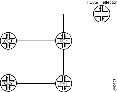
VPLSネットワークのすべてのPEルーターは、大規模な分散型イーサネットスイッチのように動作し、接続されたデバイスにレイヤー2サービスを提供します。この例では、自動検出された VPLS ネットワークを作成するための PE ルーターと CE デバイスの最小設定を示しています。トポロジーは、2つのPEルーター、2つのCEルーター、およびオプションのルートリフレクタ(RR)の5つのルーターで構成されています。PE ルーターは、BGP を使用して、両方の PE ルーターで設定された 2 つの異なる VPLS インスタンスを自動検出します。次に、PE ルーターは LDP を使用して、発見されたエンド ポイント間で 2 つの疑似配線を自動的にシグナリングします。最後に、PE ルーターは両方の VPLS インスタンスを転送トラフィック用に起動します。各 CE デバイスは 2 つの VLAN で設定され、各 VLAN は PE ルーター内の異なる VPLS インスタンスに属しています。
この例では、以下の設定を含みます。
auto-discovery-only-ルーターが、LDP ベースのレイヤー 2 VPN および VPLS 更新メッセージ(BGP_L2VPN_AD_NLRI)(FEC 129)の自動検出ネットワーク層到達可能性情報(NLRI)更新メッセージのみを処理できます。具体的には、 ステートメントはauto-discovery-only、LDP と VPLS が情報を解読して使用できるように、自動検出関連の NLRI メッセージが必要であることをルーティング プロセス(rpd)に通知します。BGPのグローバル、グループ、およびネイバーレベルでこのステートメントを設定できます。ステートメントはauto-discovery-only、VPLSのすべてのPEルーターで設定する必要があります。ルートリフレクションを設定した場合、 ステートメントは、auto-discovery-onlyFEC 129関連の更新をサポートするルートリフレクタとして機能するPルーターでも必要です。signalingこの例では、 ステートメントは含まれていませんが、ここでは完全性について説明します。ステートメントにより、ルーターはsignalingBGPベースのレイヤー2 VPN(FEC 128)に使用されるBGP_L2VPN_NLRIsのみを処理できます。PE ルーターが両方のタイプの NLRI(FEC 128 と FEC 129)をサポートする必要がある相互運用シナリオでは、 ステートメントと ステートメントの両方を
signalingauto-discovery-only設定できます。たとえば、単一の PE ルーターで、BGP 自動検出によって支援される BGP 信号の VPWS(仮想プライベート ワイヤ サービス)と LDP 信号 VPLS の組み合わせを処理する必要がある場合があります。ステートメントと ステートメントの両方をsignaling一緒にauto-discovery-only設定することで、両方のタイプのシグナリングを独立して実行できます。ステートメントはsignaling、 ステートメントと同じ階層レベルauto-discovery-onlyでサポートされています。cluster-ルートリフレクタの設定は、FEC 129自動検出PEルーターではオプションです。この例では、 ステートメントはcluster、ルーターRRをIBGPグループ内のルートリフレクタとして設定しています。インバウンド更新の場合、ルーターがルートリフレクタとして設定されている場合、または ステートメントがIBGPグループで設定されている場合keep all、BGP自動検出NLRIメッセージが受け入れられます。l2vpn-id—インスタンスのグローバル一意のレイヤー 2 VPN コミュニティ識別子を指定します。このステートメントは、タイプvplsのルーティングインスタンスで設定可能です。コミュニティ識別子には、以下のフォーマットを設定できます。
自律システム(AS)番号形式:
l2vpn-id:as-number:2-byte-number。例:l2vpn-id:100:200.AS番号は、1~65,535の範囲で指定できます。IPv4 形式—
l2vpn-id:ip-address:2-byte-number。例:l2vpn-id:10.1.1.1:2.
vrf-target— NLRI のインポートおよびエクスポート ルート ターゲットを定義します。インスタンスのvrf-targetインポートとエクスポートポリシー、またはvrf-importNLRI のインポートとエクスポートルートターゲットを定義するには、 ステートメントまたは およびvrf-exportステートメントを設定する必要があります。この例では、 ステートメントをvrf-target使用しています。route-distinguisher-BGP 自動検出 NLRI の一部を形成し、各ルートがどの VPN または VPLS ルーティング インスタンスに属するかを区別します。各ルート識別器は、6 バイト値です。ルーティングインスタンスごとに一意のルート識別を設定する必要があります。ルート識別用に以下の形式を設定できます。
AS番号形式—
as-number:2-byte-numberIPv4フォーマット—
ip-address:2-byte-number
この例には、2 つの顕著なステートメントが含まれています。これらのステートメントは、他のベンダーの機器との相互運用性にとって重要です。相互運用性ステートメントは、この例で使用するトポロジーには必要ありませんが、完全性のために含まれています。
相互運用性ステートメントは次のとおりです。
input-vlan-map pop- VLAN タグ スタックの最上位から外部 VLAN タグを削除します。output-vlan-map push-既存の VLAN タグの前に外側の VLAN タグを追加します。
構成
CLI クイックコンフィギュレーション
LDP VPLS の BGP 自動検出を迅速に設定するには、以下のコマンドをコピーして改行を削除し、各デバイスの CLI にコマンドを貼り付けます。
ルーターPE1上:
[edit]
set interfaces ge-0/1/0 vlan-tagging
set interfaces ge-0/1/0 encapsulation flexible-ethernet-services
set interfaces ge-0/1/0 unit 100 encapsulation vlan-vpls
set interfaces ge-0/1/0 unit 100 vlan-id 100
set interfaces ge-0/1/0 unit 100 input-vlan-map pop
set interfaces ge-0/1/0 unit 100 output-vlan-map push
set interfaces ge-0/1/0 unit 100 family vpls
set interfaces ge-0/1/0 unit 200 encapsulation vlan-vpls
set interfaces ge-0/1/0 unit 200 vlan-id 200
set interfaces ge-0/1/0 unit 200 family vpls
set interfaces ge-0/1/1 unit 0 description "PE1 to PE2"
set interfaces ge-0/1/1 unit 0 family inet address 192.0.2.4/24
set interfaces ge-0/1/1 unit 0 family iso
set interfaces ge-0/1/1 unit 0 family mpls
set interfaces ge-0/3/0 unit 0 description "PE1 to RR"
set interfaces ge-0/3/0 unit 0 family inet address 192.0.2.7/24
set interfaces ge-0/3/0 unit 0 family iso
set interfaces ge-0/3/0 unit 0 family mpls
set interfaces lo0 unit 0 family inet address 192.0.2.8/24
set routing-options router-id 192.0.2.8
set routing-options autonomous-system 100
set protocols mpls interface lo0.0
set protocols mpls interface all
set protocols mpls interface fxp0.0 disable
set protocols bgp group int type internal
set protocols bgp group int local-address 192.0.2.8
set protocols bgp group int family l2vpn auto-discovery-only
set protocols bgp group int neighbor 192.0.2.9
set protocols isis level 1 disable
set protocols isis interface all
set protocols isis interface fxp0.0 disable
set protocols isis interface lo0.0
set protocols ldp interface all
set protocols ldp interface fxp0.0 disable
set protocols ldp interface lo0.0
set routing-instances vpls100 instance-type vpls
set routing-instances vpls100 interface ge-0/1/0.100
set routing-instances vpls100 route-distinguisher 192.0.2.8:100
set routing-instances vpls100 l2vpn-id l2vpn-id:100:100
set routing-instances vpls100 vrf-target target:100:100
set routing-instances vpls100 protocols vpls no-tunnel-services
set routing-instances vpls200 instance-type vpls
set routing-instances vpls200 interface ge-0/1/0.200
set routing-instances vpls200 route-distinguisher 192.0.2.8:200
set routing-instances vpls200 l2vpn-id l2vpn-id:100:200
set routing-instances vpls200 vrf-target target:100:208
set routing-instances vpls200 protocols vpls no-tunnel-services
デバイスCE1上:
[edit]
set interfaces ge-1/2/1 vlan-tagging
set interfaces ge-1/2/1 mtu 1400
set interfaces ge-1/2/1 unit 100 vlan-id 100
set interfaces ge-1/2/1 unit 100 family inet address 203.0.113.3/24
set interfaces ge-1/2/1 unit 200 vlan-id 200
set interfaces ge-1/2/1 unit 200 family inet address 203.0.113.2/24
set protocols ospf area 0.0.0.0 interface ge-1/2/1.100
set protocols ospf area 0.0.0.0 interface ge-1/2/1.200
ルーターPE2上:
[edit]
set interfaces ge-1/1/0 vlan-tagging
set interfaces ge-1/1/0 encapsulation flexible-ethernet-services
set interfaces ge-1/1/0 unit 100 encapsulation vlan-vpls
set interfaces ge-1/1/0 unit 100 vlan-id 100
set interfaces ge-1/1/0 unit 100 input-vlan-map pop
set interfaces ge-1/1/0 unit 100 output-vlan-map push
set interfaces ge-1/1/0 unit 100 family vpls
set interfaces ge-1/1/0 unit 200 encapsulation vlan-vpls
set interfaces ge-1/1/0 unit 200 vlan-id 200
set interfaces ge-1/1/0 unit 200 family vpls
set interfaces ge-1/2/1 unit 0 description "PE2 to PE1"
set interfaces ge-1/2/1 unit 0 family inet address 192.0.2.14/24
set interfaces ge-1/2/1 unit 0 family iso
set interfaces ge-1/2/1 unit 0 family mpls
set interfaces lo0 unit 0 family inet address 192.0.2.10/24
set routing-options router-id 192.0.2.10
set routing-options autonomous-system 100
set protocols mpls interface lo0.0
set protocols mpls interface all
set protocols mpls interface fxp0.0 disable
set protocols bgp group int type internal
set protocols bgp group int local-address 192.0.2.10
set protocols bgp group int family l2vpn auto-discovery-only
set protocols bgp group int neighbor 192.0.2.9
set protocols isis level 1 disable
set protocols isis interface ge-1/2/1.0
set protocols isis interface lo0.0
set protocols ldp interface all
set protocols ldp interface fxp0.0 disable
set protocols ldp interface lo0.0
set routing-instances vpls100 instance-type vpls
set routing-instances vpls100 interface ge-1/1/0.100
set routing-instances vpls100 route-distinguisher 192.0.2.10:100
set routing-instances vpls100 l2vpn-id l2vpn-id:100:100
set routing-instances vpls100 vrf-target target:100:100
set routing-instances vpls100 protocols vpls no-tunnel-services
set routing-instances vpls200 instance-type vpls
set routing-instances vpls200 interface ge-1/1/0.200
set routing-instances vpls200 route-distinguisher 192.0.2.10:200
set routing-instances vpls200 l2vpn-id l2vpn-id:100:200
set routing-instances vpls200 vrf-target target:100:208
set routing-instances vpls200 protocols vpls no-tunnel-services
デバイスCE2上:
[edit]
set interfaces ge-1/1/0 vlan-tagging
set interfaces ge-1/1/0 mtu 1400
set interfaces ge-1/1/0 unit 100 vlan-id 100
set interfaces ge-1/1/0 unit 100 family inet address 203.0.113.15/24
set interfaces ge-1/1/0 unit 200 vlan-id 200
set interfaces ge-1/1/0 unit 200 family inet address 203.0.113.16/24
set protocols ospf area 0.0.0.0 interface ge-1/1/0.100
set protocols ospf area 0.0.0.0 interface ge-1/1/0.200
ルーターRRでは:
[edit]
set interfaces ge-1/3/2 unit 0 description "RR to PE1"
set interfaces ge-1/3/2 unit 0 family inet address 192.0.2.17/24
set interfaces ge-1/3/2 unit 0 family iso
set interfaces ge-1/3/2 unit 0 family mpls
set interfaces lo0 unit 0 family inet address 192.0.2.9/24
set routing-options router-id 192.0.2.9
set routing-options autonomous-system 100
set protocols bgp group int type internal
set protocols bgp group int local-address 192.0.2.9
set protocols bgp group int family l2vpn auto-discovery-only
set protocols bgp group int cluster 198.51.100.0
set protocols bgp group int neighbor 192.0.2.8
set protocols bgp group int neighbor 192.0.2.10
set protocols isis level 1 disable
set protocols isis interface all
set protocols isis interface fxp0.0 disable
set protocols isis interface lo0.0
set protocols ldp interface all
set protocols ldp interface fxp0.0 disable
set protocols ldp interface lo0.0
ルーターPE1
手順
ルーターPE1を設定するには:
インターフェイス、インターフェイスカプセル化、およびプロトコルファミリーを設定します。
[edit]
user@PE1# edit interfaces
[edit interfaces]
user@PE1# set ge-0/1/0 encapsulation flexible-ethernet-services
user@PE1# set ge-0/1/0 unit 100 encapsulation vlan-vpls
user@PE1# set ge-0/1/0 unit 100 family vpls
user@PE1# set ge-0/1/0 unit 200 encapsulation vlan-vpls
user@PE1# set ge-0/1/0 unit 200 family vpls
user@PE1# set ge-0/1/1 unit 0 description "PE1 to PE2"
user@PE1# set ge-0/1/1 unit 0 family inet address 192.0.2.4/24
user@PE1# set ge-0/1/1 unit 0 family iso
user@PE1# set ge-0/1/1 unit 0 family mpls
user@PE1# set ge-0/3/0 unit 0 description "PE1 to RR"
user@PE1# set ge-0/3/0 unit 0 family inet address 192.0.2.7/24
user@PE1# set ge-0/3/0 unit 0 family iso
user@PE1# set ge-0/3/0 unit 0 family mpls
user@PE1# set lo0 unit 0 family inet address 192.0.2.8/24
VLAN を設定します。
[edit interfaces]
user@PE1# set ge-0/1/0 vlan-tagging
user@PE1# set ge-0/1/0 unit 100 vlan-id 100
user@PE1# set ge-0/1/0 unit 100 input-vlan-map pop
user@PE1# set ge-0/1/0 unit 100 output-vlan-map push
user@PE1# set ge-0/1/0 unit 200 vlan-id 200
user@PE1# exit
プロトコル非依存のプロパティを設定します。
ルーター ID はローカル アドレスと同じにすることをお勧めします。(ステップ 4 の
local-addressステートメントを参照してください)。[edit] user@PE1# edit routing-options [edit routing-options] user@PE1# set router-id 192.0.2.8 user@PE1# set autonomous-system 100 user@PE1# exit
ステートメントを含めてIBGPを
auto-discovery-only設定します。[edit] user@PE1# edit protocols [edit protocols] user@PE1# set bgp group int type internal user@PE1# set bgp group int local-address 192.0.2.8 user@PE1# set bgp group int family l2vpn auto-discovery-only user@PE1# set bgp group int neighbor 192.0.2.9
MPLS、LDP、IGPを設定します。
[edit protocols]
user@PE1# set mpls interface lo0.0
user@PE1# set mpls interface all
user@PE1# set mpls interface fxp0.0 disable
user@PE1# set isis level 1 disable
user@PE1# set isis interface all
user@PE1# set isis interface fxp0.0 disable
user@PE1# set isis interface lo0.0
user@PE1# set ldp interface all
user@PE1# set ldp interface fxp0.0 disable
user@PE1# set ldp interface lo0.0
user@PE1# exit
ルーティングインスタンスを設定します。
インターフェイスの代わりに
vtVPLSにLSIインターフェイスを使用している場合、no-tunnel-servicesステートメントは必要です。[edit] user@PE1# edit routing-instances [edit routing-instances] user@PE1# set vpls100 instance-type vpls user@PE1# set vpls100 interface ge-0/1/0.100 user@PE1# set vpls100 route-distinguisher 192.0.2.8:100 user@PE1# set vpls100 l2vpn-id l2vpn-id:100:100 user@PE1# set vpls100 vrf-target target:100:100 user@PE1# set vpls100 protocols vpls no-tunnel-services user@PE1# set vpls200 instance-type vpls user@PE1# set vpls200 interface ge-0/1/0.200 user@PE1# set vpls200 route-distinguisher 192.0.2.8:200 user@PE1# set vpls200 l2vpn-id l2vpn-id:100:200 user@PE1# set vpls200 vrf-target target:100:208 user@PE1# set vpls200 protocols vpls no-tunnel-services
デバイスの設定が完了したら、設定をコミットします。
[edit]
user@PE1# commit
結果
設定モードから、 、show routing-optionsshow protocolsおよび のコマンドをshow interfaces入力して設定をshow routing-instances確認します。出力結果に意図した設定が表示されない場合は、この例の手順を繰り返して設定を修正します。
user@PE1# show interfaces
ge-0/1/0 {
    vlan-tagging;
    encapsulation flexible-ethernet-services;
    unit 100 {
        encapsulation vlan-vpls;
        vlan-id 100;
        input-vlan-map pop;
        output-vlan-map push;
        family vpls;
    }
    unit 200 {
        encapsulation vlan-vpls;
        vlan-id 200;
        family vpls;
    }
}
ge-0/1/1 {
    unit 0 {
        description "PE1 to PE2";
        family inet {
            address 192.0.2.4/24;
        }
        family iso;
        family mpls;
    }
}
ge-0/3/0 {
    unit 0 {
        description "PE1 to RR";
        family inet {
            address 192.0.2.7/24;
        }
        family iso;
        family mpls;
    }
}
lo0 {
    unit 0 {
        family inet {
            address 192.0.2.8/24;
        }
    }
}
user@PE1# show protocols
mpls {
    interface lo0.0;
    interface all;
    interface fxp0 disable;
}
bgp {
    group int {
        type internal;
        local-address 192.0.2.8;
        family l2vpn {
            auto-discovery-only;
        }
        neighbor 192.0.2.9;
    }
}
isis {
    level 1 disable;
    interface all;
    interface lo0.0;
    interface fxp0 disable;
}
ldp {
    interface lo0.0;
    interface all;
    interface fxp0 disable;
}
user@PE1# show routing-options
router-id 192.0.2.8;
autonomous-system 100;
user@PE1# show routing-instances
vpls100 {
    instance-type vpls;
    interface ge-0/1/0.100;
    route-distinguisher 192.0.2.8:100;
    l2vpn-id l2vpn-id:100:100;
    vrf-target target:100:100;
    protocols {
        vpls {
            no-tunnel-services;
        }
    }
}
vpls200 {
    instance-type vpls;
    interface ge-0/1/0.200;
    route-distinguisher 192.0.2.8:200;
    l2vpn-id l2vpn-id:100:200;
    vrf-target target:100:208;
    protocols {
        vpls {
            no-tunnel-services;
        }
    }
}
デバイスCE1
手順
デバイスCE1を設定するには:
インターフェイスアドレスとインターフェイスの最大送信単位(MTU)を設定します。
[edit]
user@CE1# edit interfaces
[edit interfaces]
user@CE1# set ge-1/2/1 mtu 1400
user@CE1# set ge-1/2/1 unit 100 family inet address 203.0.113.3/24
user@CE1# set ge-1/2/1 unit 200 family inet address 203.0.113.2/24
VLANを設定します。
[edit interfaces]
user@CE1# set ge-1/2/1 vlan-tagging
user@CE1# set ge-1/2/1 unit 100 vlan-id 100
user@CE1# set ge-1/2/1 unit 200 vlan-id 200
user@CE1# exit
IGPを設定します。
user@CE1# edit protocols
[edit protocols]
user@CE1# set ospf area 0.0.0.0 interface ge-1/2/1.100
user@CE1# set ospf area 0.0.0.0 interface ge-1/2/1.200
user@CE1# exit
デバイスの設定が完了したら、設定をコミットします。
[edit]
user@CE1# commit
結果
設定モードから、 および show protocols コマンドを入力して設定をshow interfaces確認します。出力結果に意図した設定が表示されない場合は、この例の手順を繰り返して設定を修正します。
user@CE1# show interfaces
ge-1/2/1 {
    vlan-tagging;
    mtu 1400;
    unit 100 {
        vlan-id 100;
        family inet {
            address 203.0.113.3/24;
        }
    }
    unit 200 {
        vlan-id 200;
        family inet {
            address 203.0.113.2/24;
        }
    }
}
user@CE1# show protocols
ospf {
    area 0.0.0.0 {
        interface ge-1/2/1.100;
        interface ge-1/2/1.200;
    }
}
ルーターPE2
手順
ルーターPE2を設定するには:
インターフェイス、インターフェイスカプセル化、およびプロトコルファミリーを設定します。
[edit]
user@PE2# edit interfaces
[edit interfaces]
user@PE2# set ge-1/1/0 encapsulation flexible-ethernet-services
user@PE2# set ge-1/1/0 unit 100 encapsulation vlan-vpls
user@PE2# set ge-1/1/0 unit 100 family vpls
user@PE2# set ge-1/1/0 unit 200 encapsulation vlan-vpls
user@PE2# set ge-1/1/0 unit 200 family vpls
user@PE2# set ge-1/2/1 unit 0 description "PE2 to PE1"
user@PE2# set ge-1/2/1 unit 0 family inet address 192.0.2.14/24
user@PE2# set ge-1/2/1 unit 0 family iso
user@PE2# set ge-1/2/1 unit 0 family mpls
user@PE2# set lo0 unit 0 family inet address 192.0.2.10/24
VLAN を設定します。
[edit interfaces]
user@PE2# set ge-1/1/0 vlan-tagging
user@PE2# set ge-1/1/0 unit 100 vlan-id 100
user@PE2# set ge-1/1/0 unit 100 input-vlan-map pop
user@PE2# set ge-1/1/0 unit 100 output-vlan-map push
user@PE2# set ge-1/1/0 unit 200 vlan-id 200
user@PE2# exit
プロトコルに依存しないプロパティを設定します。
ルーター ID はローカル アドレスと同じにすることをお勧めします。(ステップ 4 の
local-addressステートメントを参照してください)。[edit] user@PE2# edit routing-options [edit routing-options] user@PE2# set router-id 192.0.2.10 user@PE2# set autonomous-system 100
ステートメントを含めてIBGPを
auto-discovery-only設定します。[edit] user@PE2# edit protocols [edit protocols] user@PE2# set bgp group int type internal user@PE2# set bgp group int local-address 192.0.2.10 user@PE2# set bgp group int family l2vpn auto-discovery-only user@PE2# set bgp group int neighbor 192.0.2.9
MPLS、LDP、IGPを設定します。
[edit protocols]
user@PE2# set mpls interface lo0.0
user@PE2# set mpls interface all
user@PE2# set mpls interface fxp0.0 disable
user@PE2# set isis level 1 disable
user@PE2# set isis interface ge-1/2/1.0
user@PE2# set isis interface lo0.0
user@PE2# set ldp interface all
user@PE2# set ldp interface fxp0.0 disable
user@PE2# set ldp interface lo0.0
user@PE2# exit
ルーティングインスタンスを設定します。
インターフェイスの代わりに
vtVPLSにLSIインターフェイスを使用している場合、no-tunnel-servicesステートメントは必要です。[edit] user@PE2# edit routing-instances [edit routing-instances] user@PE2# set vpls100 instance-type vpls user@PE2# set vpls100 interface ge-1/1/0.100 user@PE2# set vpls100 route-distinguisher 192.0.2.10:100 user@PE2# set vpls100 l2vpn-id l2vpn-id:100:100 user@PE2# set vpls100 vrf-target target:100:100 user@PE2# set vpls100 protocols vpls no-tunnel-services user@PE2# set vpls200 instance-type vpls user@PE2# set vpls200 interface ge-1/1/0.200 user@PE2# set vpls200 route-distinguisher 192.0.2.10:200 user@PE2# set vpls200 l2vpn-id l2vpn-id:100:200 user@PE2# set vpls200 vrf-target target:100:208 user@PE2# set vpls200 protocols vpls no-tunnel-services
デバイスの設定が完了したら、設定をコミットします。
[edit]
user@PE2# commit
結果
設定モードから、 、show routing-optionsshow protocolsおよび のコマンドをshow interfaces入力して設定をshow routing-instances確認します。出力結果に意図した設定が表示されない場合は、この例の手順を繰り返して設定を修正します。
user@PE2# show interfaces
ge-1/1/0 {
    vlan-tagging;
    encapsulation flexible-ethernet-services;
    unit 100 {
        encapsulation vlan-vpls;
        vlan-id 100;
        input-vlan-map pop;
        output-vlan-map push;
        family vpls;
    }
    unit 200 {
        encapsulation vlan-vpls;
        vlan-id 200;
        family vpls;
    }
}
ge-1/2/1 {
    unit 0 {
        description "PE2 to PE1";
        family inet {
            address 192.0.2.14/24;
        }
        family iso;
        family mpls;
    }
}
lo0 {
    unit 0 {
        family inet {
            address 192.0.2.10/24;
        }
    }
}
user@PE2# show protocols
mpls {
    interface lo0.0;
    interface all;
    interface fxp0 disable;
}
bgp {
    group int {
        type internal;
        local-address 192.0.2.10;
        family l2vpn {
            auto-discovery-only;
        }
        neighbor 192.0.2.9;
    }
}
isis {
    level 1 disable;
    interface ge-1/2/1.0;
    interface lo0.0;
}
ldp {
    interface lo0.0;
    interface all;
    interface fxp0 disable;
}
user@PE2# show routing-options
router-id 192.0.2.10;
autonomous-system 100;
user@PE2# show routing-instances
vpls100 {
    instance-type vpls;
    interface ge-1/1/0.100;
    route-distinguisher 192.0.2.10:100;
    l2vpn-id l2vpn-id:100:100;
    vrf-target target:100:100;
    protocols {
        vpls {
            no-tunnel-services;
        }
    }
}
vpls200 {
    instance-type vpls;
    interface ge-1/1/0.200;
    route-distinguisher 192.0.2.10:200;
    l2vpn-id l2vpn-id:100:200;
    vrf-target target:100:208;
    protocols {
        vpls {
            no-tunnel-services;
        }
    }
}
デバイスCE2
手順
デバイスCE2を設定するには:
VLANインターフェイスを設定します。
[edit]
user@CE2# edit interfaces ge-1/1/0
[edit interfaces ge-1/1/0]
user@CE2# set vlan-tagging
user@CE2# set mtu 1400
user@CE2# set unit 100 vlan-id 100
user@CE2# set unit 100 family inet address 203.0.113.15/24
user@CE2# set unit 200 vlan-id 200
user@CE2# set unit 200 family inet address 203.0.113.16/24
user@CE2# exit
インターフェイスにOSPFを設定します。
[edit]
user@CE2# edit protocols ospf area 0.0.0.0
[edit protocols ospf area 0.0.0.0]
user@CE2# set interface ge-1/1/0.100
user@CE2# set interface ge-1/1/0.200
user@CE2# exit
デバイスの設定が完了したら、設定をコミットします。
[edit]
user@CE2# commit
結果
設定モードから、 および show protocols コマンドを入力して設定をshow interfaces確認します。出力結果に意図した設定が表示されない場合は、この例の手順を繰り返して設定を修正します。
user@CE2# show interfaces
ge-1/1/0 {
    vlan-tagging;
    mtu 1400;
    unit 100 {
        vlan-id 100;
        family inet {
            address 203.0.113.15/24;
        }
    }
    unit 200 {
        vlan-id 200;
        family inet {
            address 203.0.113.16/24;
        }
    }
}
user@CE2# show protocols
ospf {
    area 0.0.0.0 {
        interface ge-1/1/0.100;
        interface ge-1/1/0.200;
    }
}
ルーターRR
手順
ルーターRRを設定するには:
インターフェイスアドレスとプロトコルファミリーを設定します。
[edit]
user@RR# edit interfaces
[edit interfaces]
user@RR# set ge-1/3/2 unit 0 description "RR to PE1"
user@RR# set ge-1/3/2 unit 0 family inet address 192.0.2.17/24
user@RR# set ge-1/3/2 unit 0 family iso
user@RR# set ge-1/3/2 unit 0 family mpls
user@RR# set lo0 unit 0 family inet address 192.0.2.9/24
user@RR# exit
自律システムとルーター ID を設定します。
[edit]
user@RR# edit routing-options
[edit routing-options]
user@RR# set autonomous-system 100
user@RR# set router-id 192.0.2.9
user@RR# exit
BGPを設定し、このルーターをルートリフレクタに設定します。ルートリフレクションは、FEC 129ではオプションです。
[edit]
user@RR# edit protocols bgp group int
[edit protocols bgp group int]
user@RR# set type internal
user@RR# set local-address 192.0.2.9
user@RR# set family l2vpn auto-discovery-only
user@RR# set cluster 198.51.100.0
user@RR# set neighbor 192.0.2.8
user@RR# set neighbor 192.0.2.10
user@RR# exit
IGPにIS-ISを設定します。
[edit]
user@RR# edit protocols isis
[edit protocols isis]
user@RR# set level 1 disable
user@RR# set interface all
user@RR# set interface fxp0.0 disable
user@RR# set interface lo0.0
user@RR# exit
MPLS シグナリング プロトコルに LDP を設定します。
[edit]
user@RR# edit protocols ldp
[edit protocols ldp]
user@RR# set interface all
user@RR# set interface fxp0.0 disable
user@RR# set interface lo0.0
user@RR# exit
デバイスの設定が完了したら、設定をコミットします。
[edit]
user@RR# commit
結果
設定モードから、 、 、 show protocolsコマンドを入力して設定をshow interfacesshow routing-options確認します。出力結果に意図した設定が表示されない場合は、この例の手順を繰り返して設定を修正します。
user@RR# show interfaces
ge-1/3/2 {
    unit 0 {
        description "RR to PE1";
        family inet {
            address 192.0.2.17/24;
        }
        family iso;
        family mpls;
    }
}
lo0 {
    unit 0 {
        family inet {
            address 192.0.2.9/24;;
        }
    }
}
user@RR# show protocols
bgp {
    group int {
        type internal;
        local-address 192.0.2.9;
        family l2vpn {
            auto-discovery-only;
        }
        cluster 198.51.100.0;
        neighbor 192.0.2.8;
        neighbor 192.0.2.10;
    }
}
isis {
    level 1 disable;
    interface lo0.0;
    interface all;
    interface fxp0 disable;
}
ldp {
    interface lo0.0;
    interface all;
    interface fxp0 disable;
}
user@RR# show routing-options
router-id 192.0.2.9;
autonomous-system 100;
検証
操作を検証するには、以下のコマンドを使用します。
show route advertising-protocol bgp neighborshow route receive-protocol bgp neighborshow route table bgp.l2vpn.0show route table vpls100.l2vpn.0show route table vpls200.l2vpn.0show vpls connections extensiveshow vpls mac-table detail
AD は、自動検出 NLRI を示しています。