例:レイヤー 2 VPN とレイヤー 3 VPN の相互接続
この例では、レイヤー 2 VPN とレイヤー 3 VPN を相互接続および検証するための手順とコマンドを順を追って説明します。次のセクションが含まれています。
要件
この例では、以下のハードウェアとソフトウェアのコンポーネントを使用しています。
Junos OS リリース 9.3 以降
MX シリーズ ルーター 5 台
3 台の M シリーズ ルーター
2 台の T シリーズ ルーター
概要とトポロジー
レイヤー 2 VPN は、MPLS ラベルを使用してデータを転送する仮想プライベート ネットワーク(VPN)の一種です。通信は、プロバイダエッジ(PE)ルーター間で発生します。
レイヤー 2 VPN は BGP をシグナリング プロトコルとして使用するため、設計がシンプルで、レイヤー 2 回線を介した従来の VPN に比べてプロビジョニングオーバーヘッドが少なくて済みます。BGP シグナリングにより、レイヤー 2 VPN ピアの自動検出も可能になります。レイヤー 2 VPN は、フルメッシュトポロジーまたはハブアンドスポーク式トポロジーのいずれかを持つことができます。コア ネットワークのトンネリング メカニズムは、通常 MPLS です。ただし、レイヤー 2 VPN は、GRE などの他のトンネリング プロトコルも使用できます。
レイヤー 3 VPN は、RFC 2547bis、 BGP/MPLS IP VPN に基づいています。RFC 2547bis は、サービス プロバイダが自社の IP バックボーンを使用して顧客に VPN サービスを提供できるメカニズムを定義しています。レイヤー 3 VPN は、共通のルーティング情報を共有し、その接続がポリシーの集合によって制御されるサイトのセットです。レイヤー 3 VPN を構成するサイトは、プロバイダの既存のパブリック インターネット バックボーンを介して接続されます。RFC 2547bis VPN は BGP/MPLS VPN とも呼ばれ、BGP はプロバイダのバックボーン全体に VPN ルーティング情報を配信するために使用され、MPLS はバックボーンを介してリモート VPN サイトに VPN トラフィックを転送するために使用されるためです。
顧客ネットワークはプライベートであるため、RFC 1918 の「 プライベート インターネットのアドレス割り当て」で定義されているように、パブリック アドレスまたはプライベート アドレスのいずれかを使用できます。プライベート アドレスを使用する顧客ネットワークがパブリック インターネット インフラストラクチャに接続する場合、プライベート アドレスは他のネットワーク ユーザーが使用するのと同じプライベート アドレスと重複する場合があります。MPLS/BGP VPN は 、ルート識別を追加することでこの問題を解決します。ルート識別子は、特定のVPNサイトから各アドレスに追加されるVPN識別子プレフィックスであり、これによりVPN内とインターネット内の両方で一意のアドレスが作成されます。
さらに、各VPNには、そのVPNのルーティング情報のみを含む独自のVPN固有のルーティングテーブルがあります。公共インターネット内のルートや他のVPN内のルートからVPNのルートを分離するために、PEルーターはVPNルーティングおよび転送(VRF)テーブルと呼ばれるVPNごとに個別のルーティングテーブルを作成します。PE ルーターは、カスタマー エッジ(CE)ルーターに接続している VPN ごとに 1 つの VRF テーブルを作成します。VPNに属する顧客またはサイトは、そのVPNのVRFテーブル内のルートにのみアクセスできます。すべてのVRFテーブルには、特定のルーターのコレクションに属するルートを識別する、1つ以上の拡張コミュニティ属性が関連付けられています。そのうちの1つである ルートターゲット 属性は、PEルーターがルートを配布するVRFテーブル(VRFテーブル)のコレクションを特定します。PE ルーターは、ルート ターゲットを使用して、リモート ルートの VRF テーブルへのインポートを制約します。
イングレスPEルーターは、直接接続されたCEルーターからアドバタイズされたルートを受信すると、受信したルートを、そのVPNのVRFエクスポートポリシーと照合します。
一致する場合、ルートはVPN-IPv4形式に変換されます。つまり、ルート識別がルートに追加されます。その後、PE ルーターは VPN-IPv4 形式のルートをリモート PE ルーターにアナウンスします。また、直接接続されたサイトから学習した各ルートにルートターゲットをアタッチします。ルートにアタッチされたルートターゲットは、VRFテーブルで設定されたエクスポートターゲットポリシーの値に基づいています。その後、プロバイダのコア ネットワークで設定された IBGP セッションを使用してルートが分散されます。
CEルーターからのルートが一致しない場合、他のPEルーターにはエクスポートされませんが、同じVPN内の2つのCEルーターが同じPEルーターに直接接続されている場合など、ルーティングにローカルに使用することもできます。
エグレスPEルーターがルートを受信すると、PEルーター間のIBGPセッション上のインポートポリシーと照合します。受け入れられた場合、ルーターはその bgp.l3vpn.0 テーブルにルートを配置します。同時に、ルーターはVPNのVRFインポートポリシーに対してルートをチェックします。一致した場合、ルート識別子がルートから削除され、ルートはIPv4形式のVRFテーブル( routing-instance-name.inet.0テーブル)に配置されます。
トポロジ
図 1 は、レイヤー 2 VPN からレイヤー 3 VPN への相互接続の物理トポロジーを示しています。
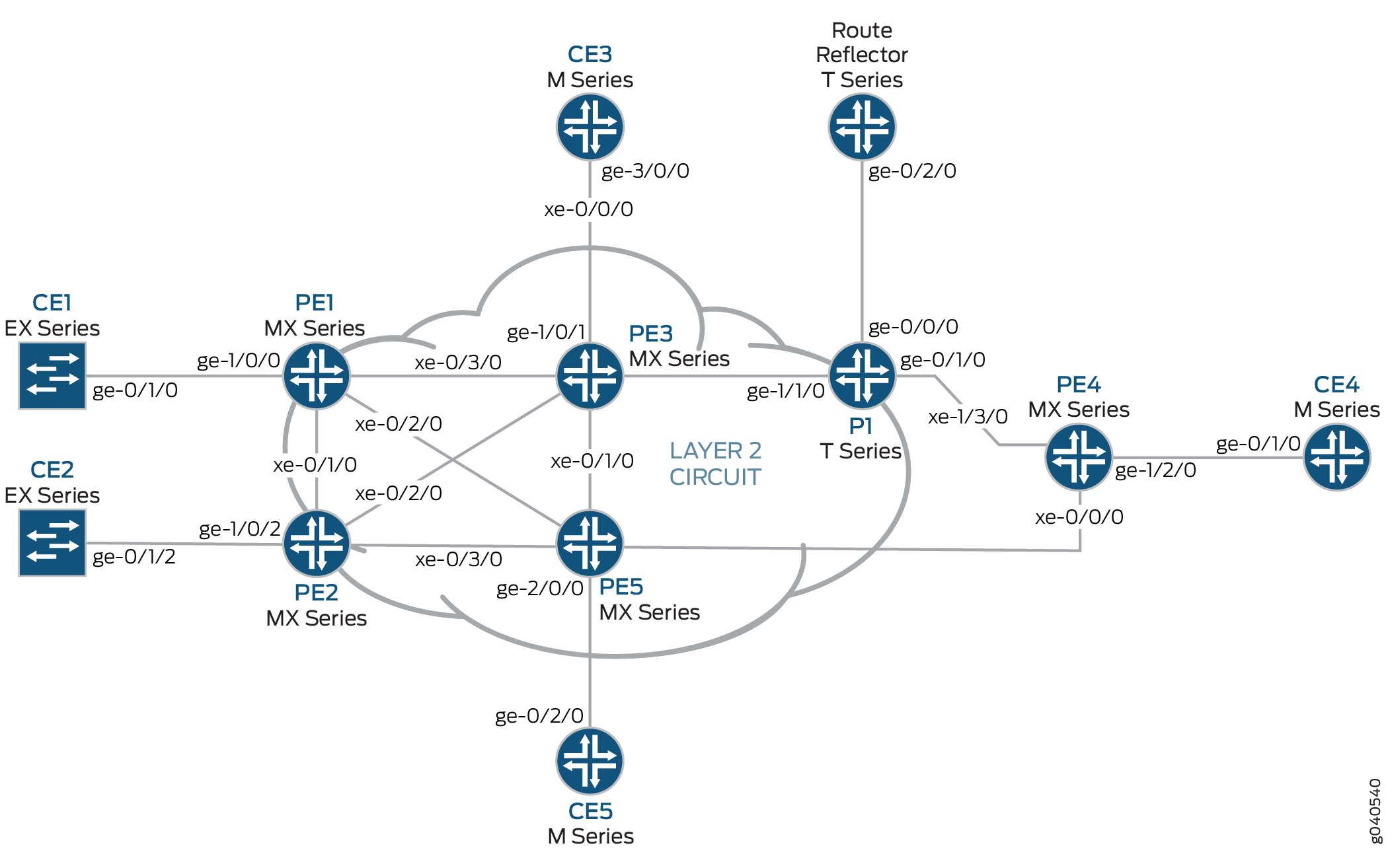 に終端する物理トポロジー
図 2 に、レイヤー 2 VPN とレイヤー 3 の VPN 相互接続の論理トポロジーを示します。
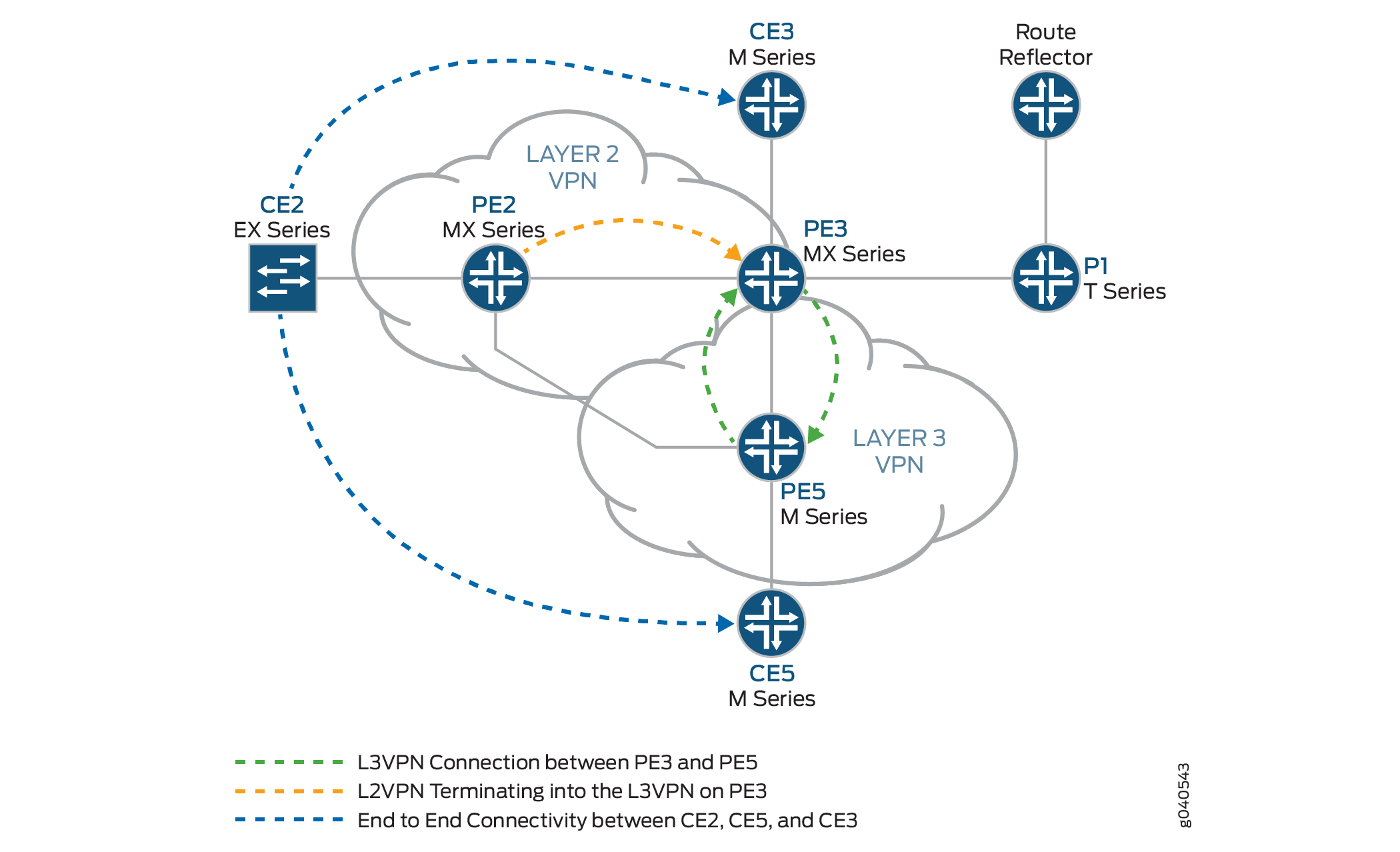 に終端する論理トポロジー
以下の定義は、 図1 および 図2で使用されるデバイス略語の意味を説明しています。
カスタマー エッジ(CE)デバイス — 1 つ以上の PE(プロバイダ エッジ)ルーターへのデータ リンクを介してサービス プロバイダの VPN へのアクセスを提供するカスタマー プレミスのデバイス。
通常、CEデバイスは、直接接続されたPEルーターとの隣接関係を確立するIPルーターです。隣接関係が確立された後、CEルーターはサイトのローカルVPNルートをPEルーターにアドバタイズし、PEルーターからリモートVPNルートを学習します。
プロバイダ エッジ(PE)デバイス — プロバイダ ネットワークのエッジにあるデバイスまたはデバイス のセットで、プロバイダが顧客サイトのビューを表示します。
PE ルーターは、CE ルーターとルーティング情報を交換します。PE ルーターはそれらを接続する VPN を認識し、PE ルーターは VPN 状態を維持します。PE ルーターは、直接接続されている VPN の VPN ルートを維持する場合にのみ必要です。CE ルーターからローカル VPN ルートを学習した後、PE ルーターは、IBGP を使用して VPN ルーティング情報を他の PE ルーターと交換します。最後に、MPLS を使用してプロバイダのバックボーンを介して VPN データ トラフィックを転送する場合、イングレス PE ルーターはイングレス LSR(ラベルスイッチング ルーター)として機能し、エグレス PE ルーターはエグレス LSR として機能します。
プロバイダ(P)デバイス—プロバイダのコア ネットワーク内で動作し、どの CE にも直接接続しないデバイス。
P デバイスは、サービス プロバイダの顧客向けに VPN を実装する際の重要な部分であり、異なる VPN に属する多くのプロバイダが運用するトンネルにルーティングを提供する場合がありますが、それ自体は VPN 認識ではなく、VPN 状態を維持しません。その主な役割は、サービス プロバイダが複数の PE ルーターのアグリゲーション ポイントとして機能するなど、VPN サービスの拡張を可能にすることです。
P ルーターは、PE ルーター間で VPN データ トラフィックを転送する場合、MPLS トランジット LSR として機能します。P ルーターは、プロバイダの PE ルーターへのルートを維持する場合にのみ必要です。各顧客サイトの特定のVPNルーティング情報を維持する必要はありません。
構成
レイヤー 2 VPN とレイヤー 3 VPN を相互接続するには、以下のタスクを実行します。
基本プロトコルとインターフェイスの設定
手順
各 PE および P ルーターで、すべてのインターフェイスでトラフィック エンジニアリング拡張機能を持つ OSPF を設定します。fxp0.0 インターフェイスで OSPF を無効にします。
[edit protocols]
ospf {
    traffic-engineering;
    area 0.0.0.0 {
        interface all;
        interface fxp0.0 {
            disable;
        }
    }
}
すべてのコア ルーターで、すべてのインターフェイスで MPLS を有効にします。fxp0.0 インターフェイスで MPLS を無効にします。
[edit protocols]
mpls {
    interface all;
    interface fxp0.0 {
        disable;
    }
}
すべてのコアルーターで、内部BGPピアグループを作成し、ルートリフレクタアドレス(192.0.2.7)をネイバーとして指定します。また、 階層レベルに ステートメントを含めることで、BGPがこのピアグループのレイヤー2 VPLSネットワーク層到達可能性情報(NLRI)メッセージを
signaling[edit protocols bgp group group-name family l2vpn]伝送できるようにします。[edit protocols] bgp { group RR { type internal; local-address 192.0.2.2; family l2vpn { signaling; } neighbor 192.0.2.7; } }ルーターPE3では、内部BGPピアグループを作成し、ルートリフレクタIPアドレス(192.0.2.7)をネイバーとして指定します。BGPがこのピアグループのレイヤー2 VPLS NLRIメッセージを伝送できるようにし、 階層レベルに ステートメントを含
unicastめることでVPN-IPv4アドレスの処理を[edit protocols bgp group group-name family inet-vpn]有効にします。[edit protocols] bgp { group RR { type internal; local-address 192.0.2.3; family inet-vpn { unicast; } family l2vpn { signaling; } neighbor 192.0.2.7; } }ルーターPE3およびルーターPE5上のレイヤー3 VPNドメインで、すべてのインターフェイスでRSVPを有効にします。fxp0.0インターフェイスでRSVPを無効にします。
[edit protocols]
rsvp {
    interface all;
    interface fxp0.0 {
        disable;
    }
}
ルーターPE3とルーターPE5で、ルートリフレクタと他のPEルーターへのラベルスイッチパス(LSP)を作成します。以下の例は、ルーターPE5の設定を示しています。
[edit protocols]
mpls {
    label-switched-path to-RR {
        to 192.0.2.7;
    }
    label-switched-path to-PE2 {
        to 192.0.2.2;
    }
    label-switched-path to-PE3 {
        to 192.0.2.3;
    }
    label-switched-path to-PE4 {
        to 192.0.2.4;
    }
    label-switched-path to-PE1 {
        to 192.0.2.1;
    }
}
ルーターPE1、PE2、PE3、およびPE5では、IPv4アドレスでコアインターフェイスを設定し、MPLSアドレスファミリーを有効にします。以下の例は、ルーターPE2上のxe-0/1/0インターフェイスの設定を示しています。
[edit]
interfaces {
    xe-0/1/0 {
        unit 0 {
            family inet {
                address 10.10.2.2/30;
            }
            family mpls;
        }
    }
}
ルーターPE2およびルーターPE3で、すべてのインターフェイスのレイヤー2 VPN MPLSシグナリングプロトコルにLDPを設定します。fxp0.0 インターフェイスで LDP を無効にします。(RSVP も使用できます。
[edit protocols]
ldp {
    interface all;
    interface fxp0.0 {
        disable;
    }
}
ルートリフレクタで、内部BGPピアグループを作成し、PEルーターのIPアドレスをネイバーとして指定します。
[edit]
protocols {
    bgp {
        group RR {
            type internal;
            local-address 192.0.2.7;
            family inet {
                unicast;
            }
            family inet-vpn {
                unicast;
            }
            family l2vpn {
                signaling;
            }
            cluster 192.0.2.7;
            neighbor 192.0.2.1;
            neighbor 192.0.2.2;
            neighbor 192.0.2.4;
            neighbor 192.0.2.5;
            neighbor 192.0.2.3;
        }
    }
}
ルートリフレクタで、ルーターPE3およびPE5に向けてMPLS LSPを設定し、inet.3ルーティングテーブルからのBGPネクストホップを解決します。
[edit]
protocols {
    mpls {
        label-switched-path to-pe3 {
            to 192.0.2.3;
        }

        label-switched-path to-pe5 {
            to 192.0.2.5;
        }
        interface all;
    }
}
VPN インターフェイスの設定
手順
ルーターPE2は、レイヤー2 VPNの一端です。ルーターPE3は、レイヤー2 VPNとレイヤー3 VPNの間でレイヤー2 VPNスティッチングを実行しています。ルーターPE3は、2つの異なるレイヤー2 VPNインスタンスの下に適用される異なる論理インターフェイスユニットで設定された論理トンネルインターフェイス(ltインターフェイス)を使用します。ルーターPE3で設定されたltインターフェイスを介して、パケットがループします。ルーターPE5の設定には、PE-CEインターフェイスが含まれています。
ルーターPE2では、ge-1/0/2インターフェイスカプセル化を設定します。階層レベルで、カプセル化ステートメントを含め、
ethernet-cccオプション(vlan-cccカプセル化もサポートされています)を[edit interfaces ge-1/0/2]指定します。カプセル化は、レイヤー2 VPNドメイン(ルーターPE2およびPE3)全体で同じである必要があります。また、インターフェイスlo0を設定します。[edit] interfaces { ge-1/0/2 { encapsulation ethernet-ccc; unit 0; } lo0 { unit 0 { family inet { address 192.0.2.2/24; } } } }ルーターPE2では、 [
edit routing-instances]階層レベルでルーティングインスタンスを設定します。また、 [edit routing-instances routing-instances-name protocols]階層レベルでレイヤー 2 VPN プロトコルを設定します。リモートサイトIDを3に設定します。サイト ID 3 は、ルーター PE3(ハブ PE)を表します。レイヤー 2 VPN は、シグナリング プロトコルとして LDP を使用しています。次の例では、ルーティング インスタンスとプロトコルの両方の 名前が 付けられているl2vpnことに注意してください。[edit] routing-instances {l2vpn{ # routing instance instance-type l2vpn; interface ge-1/0/2.0; route-distinguisher 65000:2; vrf-target target:65000:2; protocols {l2vpn{ # protocol encapsulation-type ethernet; site CE2 { site-identifier 2; interface ge-1/0/2.0 { remote-site-id 3; } } } } } }ルーターPE5では、PE-CEリンク
ge-2/0/0のギガビットイーサネットインターフェイスを設定し、インターフェイスをlo0設定します。[edit interfaces] ge-2/0/0 { unit 0 { family inet { address 198.51.100.8/24; } } } lo0 { unit 0 { } }ルーターPE5では、 階層レベルでレイヤー3 VPNルーティングインスタンス(
L3VPN)を[edit routing-instances]設定します。また、 階層レベルでBGPを設定します[edit routing-instances L3VPN protocols]。[edit] routing-instances { L3VPN { instance-type vrf; interface ge-2/0/0.0; route-distinguisher 65000:5; vrf-target target:65000:2; vrf-table-label; protocols { bgp { group ce5 { neighbor 198.51.100.2 { peer-as 200; } } } } } }ルーターPE3などのMXシリーズルーターでは、トンネルサービスに使用するトンネルサービスインターフェイスを作成する必要があります。トンネルサービスインターフェイスを作成するには、 ステートメントを
bandwidth含め、 階層レベルでトンネルサービスに予約する帯域幅をギガビット/秒で[edit chassis fpc slot-number pic slot-number tunnel-services]指定します。[edit] chassis { dump-on-panic; fpc 1 { pic 1 { tunnel-services { bandwidth 1g; } } } }ルーターPE3で、ギガビットイーサネットインターフェイスを設定します。
階層レベルに
addressステートメントを[edit interfaces ge-1/0/1.0 family inet]含め、IPアドレスとして指定198.51.100.9/24します。[edit] interfaces { ge-1/0/1 { unit 0 { family inet { address 198.51.100.9/24; } } } }ルーターPE3では、 階層レベルで論理トンネルインターフェイスを
[edit interfaces lt-1/1/10 unit 0]設定lt-1/1/10.0します。ルーターPE3は、論理トンネルインターフェイスを使用して、レイヤー2 VPNをレイヤー3 VPNにステッチングするルーターです。ピアユニットインターフェイスの設定が、相互接続を行う理由です。インターフェイスを設定するには、 ステートメントを
encapsulation含め、 オプションをethernet-ccc指定します。ステートメントをpeer-unit含め、論理インターフェイスユニット1をピアトンネルインターフェイスとして指定します。ステートメントをfamily含め、 オプションをccc指定します。[edit] interfaces { lt-1/1/10 { unit 0 { encapsulation ethernet-ccc; peer-unit 1; family ccc; } } }ルーターPE3では、 階層レベルで論理トンネルインターフェイスを
[edit interfaces lt-1/1/10 unit 1]設定lt-1/1/10.1します。インターフェイスを設定するには、 ステートメントを
encapsulation含め、 オプションをethernet指定します。ステートメントをpeer-unit含め、論理インターフェイスユニット0をピアトンネルインターフェイスとして指定します。ステートメントをfamily含め、 オプションをinet指定します。階層レベルにaddressステートメントを[edit interfaces lt-1/1/10 unit 0]含め、IPv4アドレスとして指定198.51.100.7/24します。[edit] interfaces { lt-1/1/10 { unit 1 { encapsulation ethernet; peer-unit 0; family inet { address 198.51.100.7/24; } } } }ルーターPE3では、 階層レベルで、インターフェイスユニット1をルーティングインスタンスに
[edit routing-instances L3VPN]追加ltします。インスタンスタイプvrfをpeer-unit 1とltPE-CEインターフェイスとして設定し、ルーターPE2のレイヤー2 VPNをルーターPE3のレイヤー3 VPNに終端させます。[edit] routing-instances { L3VPN { instance-type vrf; interface ge-1/0/1.0; interface lt-1/1/10.1; route-distinguisher 65000:33; vrf-target target:65000:2; vrf-table-label; protocols { bgp { export direct; group ce3 { neighbor 198.51.100.10 { peer-as 100; } } } } } }ルーターPE3では、 階層レベルでインターフェイスユニット0をルーティングインスタンスに
[edit routing-instances protocols l2vpn]追加ltします。また、レイヤー 2 VPN およびレイヤー 3 VPN ルーティング インスタンスに同じ vrf ターゲットを設定して、インスタンス間でルートを漏洩させることができます。前のステップの設定例は、ルーティングインスタンスのvrfターゲットをL3VPN示しています。以下の例は、ルーティングインスタンスのvrfターゲットをl2vpn示しています。[edit] routing-instances { l2vpn { instance-type l2vpn; interface lt-1/1/10.0; route-distinguisher 65000:3; vrf-target target:65000:2; protocols { l2vpn { encapsulation-type ethernet; site CE3 { site-identifier 3; interface lt-1/1/10.0 { remote-site-id 2; } } } } } }ルーターPE3では、 ステートメントを
policy-statement設定して、直接接続ltされたインターフェイスユニット1から学習したルートを、必要に応じてすべてのCEルーターにエクスポートして接続します。[edit] policy-options { policy-statement direct { term 1 { from protocol direct; then accept; } } }
結果
以下の出力は、ルーターPE2の完全な設定を示しています。
ルーターPE2
interfaces {
    xe-0/1/0 {
        unit 0 {
            family inet {
                address 10.10.2.2/30;
            }
            family mpls;
        }
    }
    xe-0/2/0 {
        unit 0 {
            family inet {
                address 10.10.5.1/30;
            }
            family mpls;
        }
    }
    xe-0/3/0 {
        unit 0 {
            family inet {
                address 10.10.4.1/30;
            }
            family mpls;
        }
    }
    ge-1/0/2 {
        encapsulation ethernet-ccc;
        unit 0;
    }
    fxp0 {
        apply-groups [ re0 re1 ];
    }
    lo0 {
        unit 0 {
            family inet {
                address 192.0.2.2/24;
            }
        }
    }
}
routing-options {
    static {
        route 172.0.0.0/8 next-hop 172.19.59.1;
    }
    autonomous-system 65000;
}
protocols {
    mpls {
        interface all;
        interface fxp0.0 {
            disable;
        }
    }
    bgp {
        group RR {
            type internal;
            local-address 192.0.2.2;
            family l2vpn {
                signaling;
            }
            neighbor 192.0.2.7;
        }
    }
    ospf {
        traffic-engineering;
        area 0.0.0.0 {
            interface all;
            interface fxp0.0 {
                disable;
            }
        }
    }
    ldp {
        interface all;
        interface fxp0.0 {
            disable;
        }
    }
}
routing-instances {
    l2vpn {
        instance-type l2vpn;
        interface ge-1/0/2.0;
        route-distinguisher 65000:2;
        vrf-target target:65000:2;
        protocols {
            l2vpn {
                encapsulation-type ethernet;
                site CE2 {
                    site-identifier 2;
                    interface ge-1/0/2.0 {
                        remote-site-id 3;
                    }
                }
            }
        }
    }
}
以下の出力は、ルーターPE5の最終設定を示しています。
ルーターPE5
interfaces {
    ge-0/0/0 {
        unit 0 {
            family inet {
                address 10.10.4.2/30;
            }
            family mpls;
        }
    }
    xe-0/1/0 {
        unit 0 {
            family inet {
                address 10.10.6.2/30;
            }
            family mpls;
        }
    }
    ge-1/0/0 {
        unit 0 {
            family inet {
                address 10.10.9.1/30;
            }
            family mpls;
        }
    }
    xe-1/1/0 {
        unit 0 {
            family inet {
                address 10.10.3.2/30;
            }
            family mpls;
        }
    }
    ge-2/0/0 {
        unit 0 {
            family inet {
                address 198.51.100.8/24;
            }
        }
    }
    lo0 {
        unit 0 {
            family inet {
                address 192.0.2.5/24;
            }
        }
    }
}
routing-options {
    static {
        route 172.0.0.0/8 next-hop 172.19.59.1;
    }
    autonomous-system 65000;
}
protocols {
    rsvp {
        interface all {
            link-protection;
        }
        interface fxp0.0 {
            disable;
        }
    }
    mpls {
        label-switched-path to-RR {
            to 192.0.2.7;
        }
        label-switched-path to-PE2 {
            to 192.0.2.2;
        }
        label-switched-path to-PE3 {
            to 192.0.2.3;
        }
        label-switched-path to-PE4 {
            to 192.0.2.4;
        }
        label-switched-path to-PE1 {
            to 192.0.2.1;
        }
        interface all;
        interface fxp0.0 {
            disable;
        }

    }
    bgp {
        group to-rr {
            type internal;
            local-address 192.0.2.5;
            family inet-vpn {
                unicast;
            }
            family l2vpn {
                signaling;
            }
            neighbor 192.0.2.7;
        }
    }
    ospf {
        traffic-engineering;
        area 0.0.0.0 {
            interface all;
            interface fxp0.0 {
                disable;
            }
        }
    }
    ldp {
        interface all;
        interface fxp0.0 {
            disable;
        }
    }
}
routing-instances {
    L3VPN {
        instance-type vrf;
        interface ge-2/0/0.0;
        route-distinguisher 65000:5;
        vrf-target target:65000:2;
        vrf-table-label;
        protocols {
            bgp {
                group ce5 {
                    neighbor 198.51.100.2 {
                        peer-as 200;
                    }
                }
            }
        }
    }
}
以下の出力は、ルーターPE3の最終設定を示しています。
ルーターPE3
chassis {
    dump-on-panic;
    fpc 1 {
        pic 1 {
            tunnel-services {
                bandwidth 1g;
            }
        }
    }
    network-services ip;
}
interfaces {
    ge-1/0/1 {
        unit 0 {
            family inet {
                address 198.51.100.9/24;
            }
        }
    }
    lt-1/1/10 {
        unit 0 {
            encapsulation ethernet-ccc;
            peer-unit 1;
            family ccc;
        }
        unit 1 {
            encapsulation ethernet;
            peer-unit 0;
            family inet {
                address 198.51.100.7/24;
            }
        }
    }
    xe-2/0/0 {
        unit 0 {
            family inet {
                address 10.10.20.2/30;
            }
            family mpls;
        }
    }
    xe-2/1/0 {
        unit 0 {
            family inet {
                address 10.10.6.1/30;
            }
            family mpls;
        }
    }
    xe-2/2/0 {
        unit 0 {
            family inet {
                address 10.10.5.2/30;
            }
            family mpls;
        }
    }
    xe-2/3/0 {
        unit 0 {
            family inet {
                address 10.10.1.2/30;
            }
            family mpls;
        }
    }
    lo0 {
        unit 0 {
            family inet {
                address 192.0.2.3/24;
            }
        }
    }
}
routing-options {
    static {
        route 172.0.0.0/8 next-hop 172.19.59.1;
    }
    autonomous-system 65000;
}
protocols {
    rsvp {
        interface all;
        interface fxp0.0 {
            disable;
        }
    }
    mpls {
        label-switched-path to-RR {
            to 192.0.2.7;
        }
        label-switched-path to-PE2 {
            to 192.0.2.2;
        }
        label-switched-path to-PE5 {
            to 192.0.2.5;
        }
        label-switched-path to-PE4 {
            to 192.0.2.4;
        }
        label-switched-path to-PE1 {
            to 192.0.2.1;
        }
        interface all;
        interface fxp0.0 {
            disable;
        }
    }
    bgp {
        group RR {
            type internal;
            local-address 192.0.2.3;
            family inet-vpn {
                unicast;
            }
            family l2vpn {
                signaling;
            }
            neighbor 192.0.2.7;
        }
    }
    ospf {
        traffic-engineering;
        area 0.0.0.0 {
            interface all;
            interface fxp0.0 {
                disable;
            }
        }
    }
    ldp {
        interface all;
        interface fxp0.0 {
            disable;
        }
    }
}
policy-options {
    policy-statement direct {
        term 1 {
            from protocol direct;
            then accept;
        }
    }
}
routing-instances {
    L3VPN {
        instance-type vrf;
        interface ge-1/0/1.0;
        interface lt-1/1/10.1;
        route-distinguisher 65000:33;
        vrf-target target:65000:2;
        vrf-table-label;
        protocols {
            bgp {
                export direct;
                group ce3 {
                    neighbor 198.51.100.10 {
                        peer-as 100;
                    }
                }
            }
        }
    }
    l2vpn {
        instance-type l2vpn;
        interface lt-1/1/10.0;
        route-distinguisher 65000:3;
        vrf-target target:65000:2;
        protocols {
            l2vpn {
                encapsulation-type ethernet;
                site CE3 {
                    site-identifier 3;
                    interface lt-1/1/10.0 {
                        remote-site-id 2;
                    }
                }
            }
        }
    }
}
検証
レイヤー 2 VPN からレイヤー 3 VPN への相互接続を検証します。
ルーターPE2 VPNインターフェイスの検証
目的
レイヤー 2 VPN が稼働し、ルーター PE2 インターフェイスで動作していること、およびすべてのルートが存在していることを確認します。
アクション
コマンドを
show l2vpn connections使用して、ルーターPE3の接続サイトIDが3であり、ステータスが であることをUp確認します。user@PE2> show l2vpn connections Layer-2 VPN connections: Legend for connection status (St) EI -- encapsulation invalid NC -- interface encapsulation not CCC/TCC/VPLS EM -- encapsulation mismatch WE -- interface and instance encaps not same VC-Dn -- Virtual circuit down NP -- interface hardware not present CM -- control-word mismatch -> -- only outbound connection is up CN -- circuit not provisioned <- -- only inbound connection is up OR -- out of range Up -- operational OL -- no outgoing label Dn -- down LD -- local site signaled down CF -- call admission control failure RD -- remote site signaled down SC -- local and remote site ID collision LN -- local site not designated LM -- local site ID not minimum designated RN -- remote site not designated RM -- remote site ID not minimum designated XX -- unknown connection status IL -- no incoming label MM -- MTU mismatch MI -- Mesh-Group ID not available BK -- Backup connection ST -- Standby connection PF -- Profile parse failure PB -- Profile busy RS -- remote site standby Legend for interface status Up -- operational Dn -- down Instance: l2vpn Local site: CE2 (2) connection-site Type St Time last up # Up trans 3 rmt Up Jan 7 14:14:37 2010 1 Remote PE: 192.0.2.3, Negotiated control-word: Yes (Null) Incoming label: 800000, Outgoing label: 800001 Local interface: ge-1/0/2.0, Status: Up, Encapsulation: ETHERNETコマンドを
show route table使用して、レイヤー2 VPNルートが存在し、インターフェイスを介したxe-0/2/0.0ネクストホップ10.10.5.2があることを確認します。以下の出力では、レイヤー2 VPNルートがl2vpn.l2vpn.0テーブルに存在することを確認します。ルーターPE3にも同様の出力を表示する必要があります。user@PE2> show route table l2vpn.l2vpn.0 l2vpn.l2vpn.0: 2 destinations, 2 routes (2 active, 0 holddown, 0 hidden) + = Active Route, - = Last Active, * = Both 65000:2:2:3/96 *[L2VPN/170/-101] 02:40:35, metric2 1 Indirect 65000:3:3:1/96 *[BGP/170] 02:40:35, localpref 100, from 192.0.2.7 AS path: I > to 10.10.5.2 via xe-0/2/0.0ルーターPE2に、ルーターPE3の双方向(PUSHとPOP)を指すLDPラベルを指すレイヤー2 VPN MPLSラベルがあることを確認します。
user@PE2> show route table mpls.0
 mpls.0: 13 destinations, 13 routes (13 active, 0 holddown, 0 hidden)
+ = Active Route, - = Last Active, * = Both

0                  *[MPLS/0] 1w3d 08:57:41, metric 1
                      Receive
1                  *[MPLS/0] 1w3d 08:57:41, metric 1
                      Receive
2                  *[MPLS/0] 1w3d 08:57:41, metric 1
                      Receive
300560             *[LDP/9] 19:45:53, metric 1
                    > to 10.10.2.1 via xe-0/1/0.0, Pop
300560(S=0)        *[LDP/9] 19:45:53, metric 1
                    > to 10.10.2.1 via xe-0/1/0.0, Pop
301008             *[LDP/9] 19:45:53, metric 1
                    > to 10.10.4.2 via xe-0/3/0.0, Swap 299856
301536             *[LDP/9] 19:45:53, metric 1
                    > to 10.10.4.2 via xe-0/3/0.0, Pop
301536(S=0)        *[LDP/9] 19:45:53, metric 1
                    > to 10.10.4.2 via xe-0/3/0.0, Pop
301712             *[LDP/9] 16:14:52, metric 1
                    > to 10.10.5.2 via xe-0/2/0.0, Swap 315184
301728             *[LDP/9] 16:14:52, metric 1
                    > to 10.10.5.2 via xe-0/2/0.0, Pop
301728(S=0)        *[LDP/9] 16:14:52, metric 1
                    > to 10.10.5.2 via xe-0/2/0.0, Pop
800000             *[L2VPN/7] 02:40:35
                    > via ge-1/0/2.0, Pop       Offset: 4
ge-1/0/2.0         *[L2VPN/7] 02:40:35, metric2 1
                    > to 10.10.5.2 via xe-0/2/0.0, Push 800001 Offset: -4
意味
ルーティングインスタンスは l2vpn インターフェイス ge-1/0/2 で稼働しており、レイヤー2 VPNルートはテーブルl2vpn.l2vpn.0に示されています。表 mpls.0 は、LDPラベルを使用してトラフィックを転送するために使用されるレイヤー2 VPNルートを示しています。
ルーターPE3 VPNインターフェイスの検証
目的
ルーターPE2およびルーターPE3からのレイヤー2 VPN接続が Up 動作していることを確認します。
アクション
ファミリーとファミリー
l2vpn-signalinginet-vpnのルートリフレクタとのBGPセッションが確立されていることを確認します。user@PE3> show bgp summary Groups: 2 Peers: 2 Down peers: 0 Table Tot Paths Act Paths Suppressed History Damp State Pending bgp.l2vpn.0 1 1 0 0 0 0 bgp.L3VPN.0 1 1 0 0 0 0 Peer AS InPkt OutPkt OutQ Flaps Last Up/Dwn State|#Active /Received/Accepted/Damped... 192.0.2.7 65000 2063 2084 0 1 15:35:16 Establ bgp.l2vpn.0: 1/1/1/0 bgp.L3VPN.0: 1/1/1/0 L3VPN.inet.0: 1/1/1/0 l2vpn.l2vpn.0: 1/1/1/0
以下の出力では、レイヤー2 VPNルートとそれに関連するラベルを検証します。
user@PE3> show route table l2vpn.l2vpn.0 detail
l2vpn.l2vpn.0: 2 destinations, 2 routes (2 active, 0 holddown, 0 hidden)
65000:2:2:3/96 (1 entry, 1 announced)
        *BGP    Preference: 170/-101
                Route Distinguisher: 65000:2
                Next hop type: Indirect
                Next-hop reference count: 4
                Source: 192.0.2.7
                Protocol next hop: 192.0.2.2
                Indirect next hop: 2 no-forward
                State: <Secondary Active Int Ext>
                Local AS: 65000 Peer AS: 65000
                Age: 2:45:52    Metric2: 1
                Task: BGP_65000.192.0.2.7+60585
                Announcement bits (1): 0-l2vpn-l2vpn
                AS path: I (Originator) Cluster list:  192.0.2.7
                AS path:  Originator ID: 192.0.2.2
                Communities: target:65000:2 Layer2-info: encaps:ETHERNET, control flags:Control-Word, mtu: 0, site preference: 100  Accepted
                Label-base: 800000, range: 2, status-vector: 0x0
                Localpref: 100
                Router ID: 192.0.2.7
                Primary Routing Table bgp.l2vpn.0
以下の出力は、mpls.0 ルート テーブル内の L2VPN MPLS.0 ルートを示しています。
user@PE3> show route table mpls.0
mpls.0: 21 destinations, 21 routes (21 active, 0 holddown, 0 hidden)
+ = Active Route, - = Last Active, * = Both

0                  *[MPLS/0] 1w3d 09:05:41, metric 1
                      Receive
1                  *[MPLS/0] 1w3d 09:05:41, metric 1
                      Receive
2                  *[MPLS/0] 1w3d 09:05:41, metric 1
                      Receive
16                 *[VPN/0] 15:59:24
                      to table L3VPN.inet.0, Pop
315184             *[LDP/9] 16:21:53, metric 1
                    > to 10.10.20.1 via xe-2/0/0.0, Pop
315184(S=0)        *[LDP/9] 16:21:53, metric 1
                    > to 10.10.20.1 via xe-2/0/0.0, Pop
315200             *[LDP/9] 01:13:44, metric 1
                      to 10.10.20.1 via xe-2/0/0.0, Swap 625297
                    > to 10.10.6.2 via xe-2/1/0.0, Swap 299856
315216             *[LDP/9] 16:21:53, metric 1
                    > to 10.10.6.2 via xe-2/1/0.0, Pop
315216(S=0)        *[LDP/9] 16:21:53, metric 1
                    > to 10.10.6.2 via xe-2/1/0.0, Pop
315232             *[LDP/9] 16:21:45, metric 1
                    > to 10.10.1.1 via xe-2/3/0.0, Pop
315232(S=0)        *[LDP/9] 16:21:45, metric 1
                    > to 10.10.1.1 via xe-2/3/0.0, Pop
315248             *[LDP/9] 16:21:53, metric 1
                    > to 10.10.5.1 via xe-2/2/0.0, Pop
315248(S=0)        *[LDP/9] 16:21:53, metric 1
                    > to 10.10.5.1 via xe-2/2/0.0, Pop
315312             *[RSVP/7] 15:02:40, metric 1
                    > to 10.10.6.2 via xe-2/1/0.0, label-switched-path to-pe5
315312(S=0)        *[RSVP/7] 15:02:40, metric 1
                    > to 10.10.6.2 via xe-2/1/0.0, label-switched-path to-pe5
315328             *[RSVP/7] 15:02:40, metric 1
                    > to 10.10.20.1 via xe-2/0/0.0, label-switched-path to-RR
315360             *[RSVP/7] 15:02:40, metric 1
                    > to 10.10.20.1 via xe-2/0/0.0, label-switched-path to-RR
316272             *[RSVP/7] 01:13:27, metric 1
                    > to 10.10.6.2 via xe-2/1/0.0, label-switched-path Bypass->10.10.9.1
316272(S=0)        *[RSVP/7] 01:13:27, metric 1
                    > to 10.10.6.2 via xe-2/1/0.0, label-switched-path Bypass->10.10.9.1
800001             *[L2VPN/7] 02:47:33
                    > via lt-1/1/10.0, Pop       Offset: 4
lt-1/1/10.0        *[L2VPN/7] 02:47:33, metric2 1
                    > to 10.10.5.1 via xe-2/2/0.0, Push 800000 Offset: -4
show route table mpls.0オプション付きの コマンドをdetail使用して、ネクストホップタイプやラベル操作などのルートのBGP属性を表示します。user@PE5> show route table mpls.0 detail lt-1/1/10.0 (1 entry, 1 announced) *L2VPN Preference: 7 Next hop type: Indirect Next-hop reference count: 2 Next hop type: Router, Next hop index: 607 Next hop: 10.10.5.1 via xe-2/2/0.0, selected Label operation: Push 800000 Offset: -4 Protocol next hop: 192.0.2.2 Push 800000 Offset: -4 Indirect next hop: 8cae0a0 1048574 State: <Active Int> Age: 2:46:34 Metric2: 1 Task: Common L2 VC Announcement bits (2): 0-KRT 2-Common L2 VC AS path: I Communities: target:65000:2 Layer2-info: encaps:ETHERNET, control flags:Control-Word, mtu: 0, site preference: 100
ルーターCE2からルーターCE5およびルーターCE3へのエンドツーエンド接続の検証
目的
ルーターCE2、CE3、およびCE5間の接続を確認します。
アクション
ルーター CE2 からルーター CE3 IP アドレスを Ping します。
user@CE2> ping 198.51.100.10 # CE3 IP address
PING 198.51.100.10 (198.51.100.10): 56 data bytes
64 bytes from 198.51.100.10: icmp_seq=0 ttl=63 time=0.708 ms
64 bytes from 198.51.100.10: icmp_seq=1 ttl=63 time=0.610 ms
ルーター CE2 からルーター CE5 IP アドレスを Ping します。
user@CE2> ping 198.51.100.2 # CE5 IP address
PING 198.51.100.2 (198.51.100.2): 56 data bytes
64 bytes from 198.51.100.2: icmp_seq=0 ttl=62 time=0.995 ms
64 bytes from 198.51.100.2: icmp_seq=1 ttl=62 time=1.005 ms