例:レイヤー 2 VPN とレイヤー 2 VPN の相互接続
この例では、レイヤー 2 VPN とレイヤー 2 VPN を相互接続して検証する手順を順を追って説明します。次のセクションが含まれています。
要件
この例では、以下のハードウェアとソフトウェアのコンポーネントを使用しています。
Junos OS リリース 9.3 以降
2つのMXシリーズ5Gユニバーサルルーティングプラットフォーム
2 M シリーズ マルチサービス エッジ ルーター
1 T シリーズ コア ルーター
EX シリーズ イーサネット スイッチ x 1
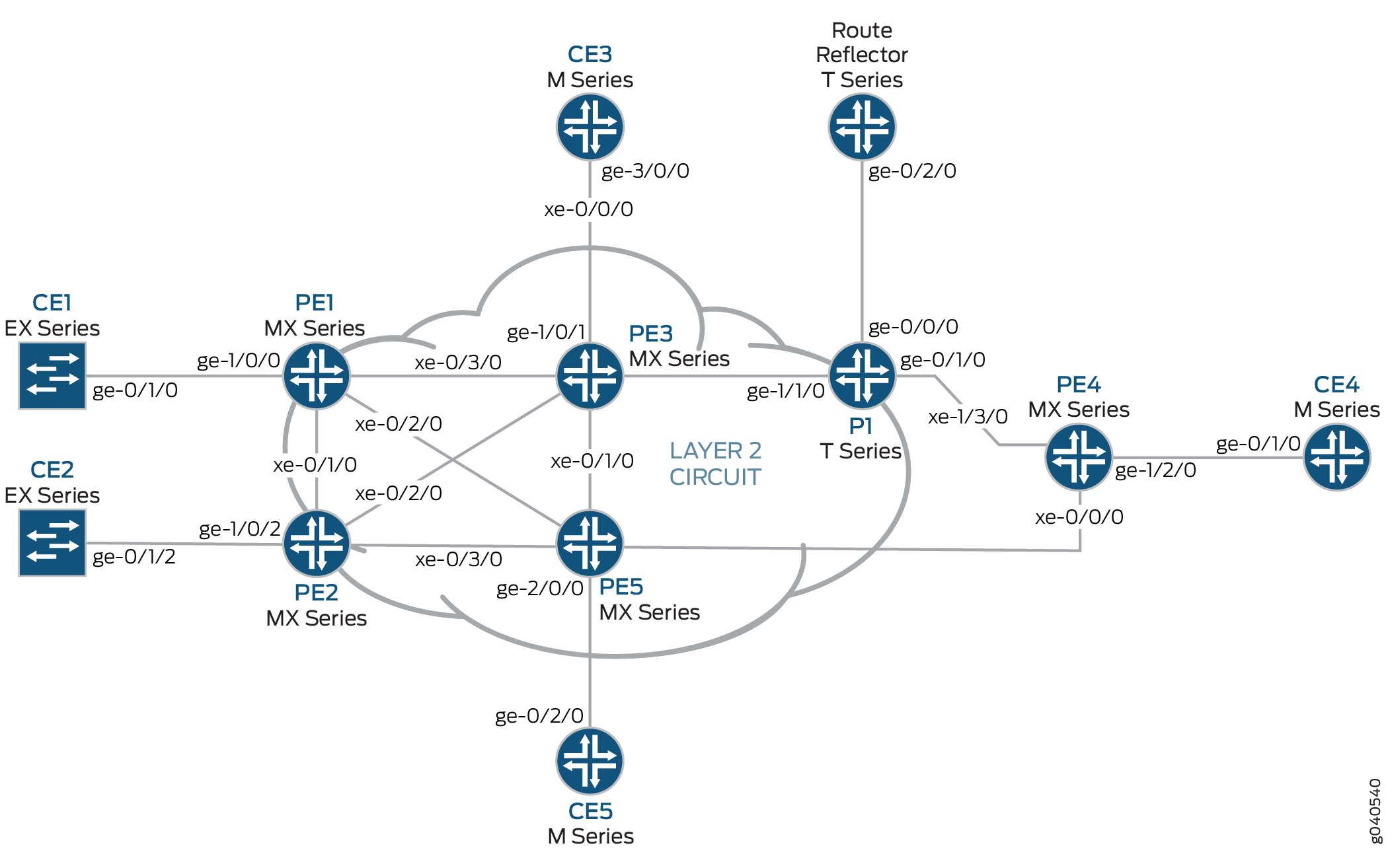
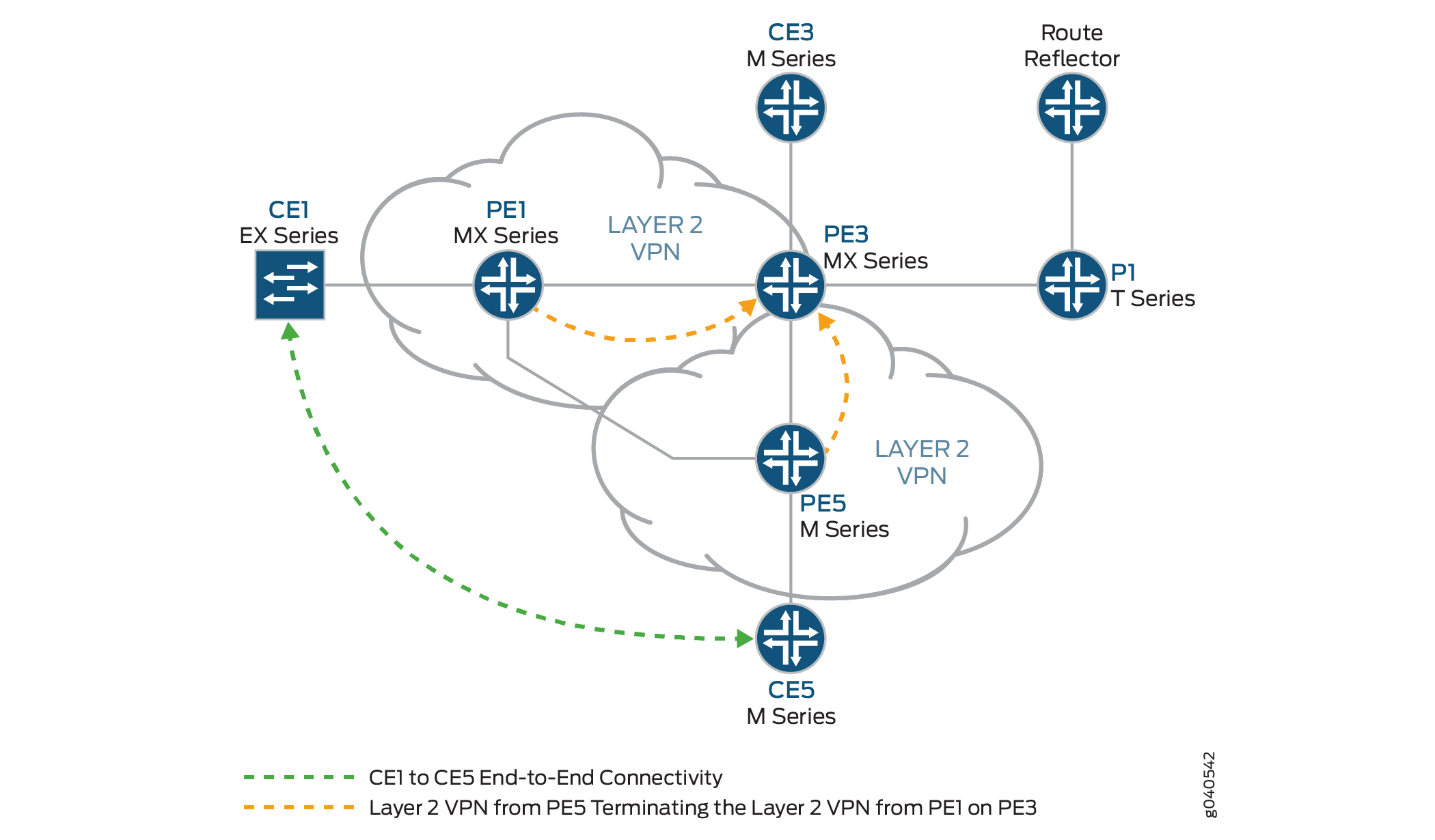
概要とトポロジー
構成
どの設定セッションでも、 コマンドを使用して commit check 設定をコミットできることを定期的に確認することをお勧めします。
この例では、設定されているルーターが次のコマンド プロンプトを使用して識別されます。
CE1カスタマーエッジ1(CE1)ルーターを識別します。PE1は、プロバイダ エッジ 1(PE1)ルーターを識別します。CE3カスタマー エッジ 3(CE3)ルーターを識別します。PE3は、プロバイダ エッジ 3(PE3)ルーターを識別します。CE5カスタマーエッジ5(CE5)ルーターを識別します。PE5は、プロバイダ エッジ 5(PE5)ルーターを識別します。
この例は、以下のセクションで構成されています。
- PE および P ルーターでのプロトコルの設定
- ルーターPE3でのレイヤー2 VPNからレイヤー2 VPNへの接続の検証
- ルーターPE3でのレイヤー2 VPNからレイヤー2 VPNへの接続の検証
- 結果
PE および P ルーターでのプロトコルの設定
手順
すべての PE ルーターと P ルーターは、IGP プロトコルとして OSPF で設定されています。MPLS、LDP、および BGP プロトコルは、 を除く fxp.0すべてのインターフェイスで有効になっています。コアに面したインターフェイスは、MPLS アドレスと inet アドレスで有効になっています。
すべてのPEおよびPルーターをOSPFをIGPとして設定します。を除く
fxp.0すべてのインターフェイスで MPLS、LDP、BGP プロトコルを有効にします。以下の設定スニペットは、ルーターPE1のプロトコル設定を示しています。[edit] protocols { mpls { interface all; interface fxp0.0 { disable; } } bgp { group RR { type internal; local-address 192.0.2.1; family l2vpn { signaling; } neighbor 192.0.2.7; } } ospf { traffic-engineering; area 0.0.0.0 { interface all; interface fxp0.0 { disable; } } } ldp { interface all; interface fxp0.0 { disable; } } }OSPF を IGP として PE および P ルーターを設定します。を除く
fxp.0すべてのインターフェイスで MPLS、LDP、BGP プロトコルを有効にします。以下の設定スニペットは、ルーターPE3のプロトコル設定を示しています。[edit] protocols { mpls { interface all; interface fxp0.0 { disable; } } bgp { group RR { type internal; local-address 192.0.2.3; family l2vpn { signaling; } neighbor 192.0.2.7; } } ospf { traffic-engineering; area 0.0.0.0 { interface all; interface fxp0.0 { disable; } } } ldp { interface all; interface fxp0.0 { disable; } } }
手順
レイヤー 2 VPN プロトコルとインターフェイスの設定
ルーターPE1で、インターフェイスカプセル化を
ge-1/0/0設定します。インターフェイスカプセル化を設定するには、 ステートメントをencapsulation含め、 オプションを指定しますethernet-ccc(vlan-cccカプセル化もサポートされています)。ge-1/0/0.0回線クロスコネクト機能の論理インターフェイスファミリーを設定します。論理インターフェイスファミリーを設定するには、 ステートメントをfamily含め、 オプションをccc指定します。カプセル化は、レイヤー2 VPNドメインのすべてのルーターに同じ方法で設定する必要があります。[edit interfaces] ge-1/0/0 { encapsulation ethernet-ccc; unit 0 { family ccc; } } lo0 { unit 0 { family inet { address 192.0.2.1/24; } } }ルーターPE1で、レイヤー2 VPNプロトコルを設定します。リモートサイトIDを3に設定します。サイト ID 3 は、ルーター PE3(ハブ PE)を表します。レイヤー 2 VPN プロトコルを設定するには、 階層レベルで ステートメントを
[edit routing-instances routing-instances-name protocols]含l2vpnめます。レイヤー 2 VPN は、シグナリング プロトコルとして BGP を使用します。[edit routing-instances] L2VPN { instance-type l2vpn; interface ge-1/0/0.0; route-distinguisher 65000:1; vrf-target target:65000:2; protocols { l2vpn { encapsulation-type ethernet; site CE1 { site-identifier 1; interface ge-1/0/0.0 { remote-site-id 3; } } } } }ルーターPE5では、 ステートメントを
ge-2/0/0含めてインターフェイスカプセル化をencapsulation設定し、 オプションをethernet-ccc指定します。ステートメントを含familyめ、 オプションを指定して、回線クロスコネクト機能のge-1/0/0.0論理インターフェイスファミリーをccc設定します。[edit interfaces] ge-2/0/0 { encapsulation ethernet-ccc; unit 0 { family ccc; } } lo0 { unit 0 { family inet { address 192.0.2.5/24; } } }ルーターPE5では、 階層レベルで ステートメントを
l2vpn含めてレイヤー2 VPNプロトコルを[edit routing-instances routing-instances-name protocols]設定します。リモート サイト ID を として3設定します。[edit routing-instances] L2VPN { instance-type l2vpn; interface ge-2/0/0.0; route-distinguisher 65000:5; vrf-target target:65000:2; protocols { l2vpn { encapsulation-type ethernet; site CE5 { site-identifier 5; interface ge-2/0/0.0 { remote-site-id 3; } } } } }ルーターPE3では、2つの論理インターフェイスでインターフェイスを設定
iw0します。インターフェイスをiw0設定するには、 ステートメントをinterfaces含め、 をインターフェイス名に指定iw0します。ユニット0の論理インターフェイスには、 ステートメントをpeer-unit含め、論理インターフェイスをピアインターフェイスunit 1として指定します。ユニット1の論理インターフェイスには、 ステートメントをpeer-unit含め、論理インターフェイスをピアインターフェイスunit 0として指定します。[edit interfaces] iw0 { unit 0 { encapsulation ethernet-ccc; peer-unit 1; } unit 1 { encapsulation ethernet-ccc; peer-unit 0; } }ルーターPE3では、 ステートメントを含め、 オプションを
encapsulation指定して、エッジに面ge-1/0/1したインターフェイスカプセル化をethernet-ccc設定します。[edit interfaces] ge-1/0/1 { encapsulation ethernet-ccc; unit 0 { family ccc; } }ルーターPE3で、論理ループバックインターフェイスを設定します。ループバックインターフェイスは、ルーターPE1およびルーターPE5へのターゲットLDPセッションを確立するために使用されます。
[edit interfaces]
lo0 {
    unit 0 {
        family inet {
            address 192.0.2.3/24;
        }
    }
}
ルーターPE3で、レイヤー2インターワーキングプロトコルを有効にします。レイヤー 2 インターワーキング プロトコルを有効にするには、 階層レベルで ステートメントを
[edit protocols]含l2iwめます。[edit protocols] l2iw;
ルーターPE3では、に示すように、2つのレイヤー2 VPNルーティングインスタンスを設定して、ルーターPE1とルーターPE5からレイヤー2 VPN仮想回線を終端します。
[edit routing-instances]
L2VPN-PE1 {
    instance-type l2vpn;
    interface iw0.0;
    route-distinguisher 65000:3;
    vrf-target target:65000:2;
    protocols {
        l2vpn {
            encapsulation-type ethernet;
            site CE3 {
                site-identifier 3;
                interface iw0.0 {
                    remote-site-id 1;
                }
            }
        }
    }
}
L2VPN-PE5 {
    instance-type l2vpn;
    interface iw0.1;
    route-distinguisher 65000:33;
    vrf-target target:65000:2;
    protocols {
        l2vpn {
            encapsulation-type ethernet;
            site CE3 {
                site-identifier 3;
                interface iw0.1 {
                    remote-site-id 5;
                }
            }
        }
    }
}
ルーターPE3でのレイヤー2 VPNからレイヤー2 VPNへの接続の検証
手順
BGP は、レイヤー 2 VPN のコントロール プレーン シグナリングに使用されます。ルーターPE1では、 コマンドを
show bgp使用して、レイヤー2 VPNのBGPコントロールプレーンが、IPアドレスを持つルートリフレクタとのネイバー関係を確立していることを確認します192.0.2.7。トポロジー内の各 PE ルーターのルート リフレクタから 3 つのレイヤー 2 VPN ルートを受信します。
user@PE1> show bgp summary
Groups: 1 Peers: 1 Down peers: 0
Table          Tot Paths  Act Paths Suppressed    History Damp State    Pending
bgp.l2vpn.0            3          3          0          0          0          0
Peer                     AS      InPkt     OutPkt    OutQ   Flaps Last Up/Dwn State|#Active/Received/Accepted/Damped...
192.0.2.7               65000        190        192       0       0     1:24:40 Establ
  bgp.l2vpn.0: 3/3/3/0
  L2VPN.l2vpn.0: 3/3/3/0
ルーターPE1では、 コマンドを
show route使用して、BGPレイヤー2 VPNルートが各PEルーターのルーティングテーブルにL2VPN.l2vpn.0格納されていることを確認します。user@PE1> show route table L2VPN.l2vpn.0 L2VPN.l2vpn.0: 4 destinations, 4 routes (4 active, 0 holddown, 0 hidden) + = Active Route, - = Last Active, * = Both 65000:1:1:3/96 *[L2VPN/170/-101] 01:31:53, metric2 1 Indirect 65000:3:3:1/96 *[BGP/170] 01:24:58, localpref 100, from 192.0.2.7 AS path: I > to 10.10.1.2 via xe-0/3/0.0 65000:5:5:3/96 *[BGP/170] 01:24:58, localpref 100, from 192.0.2.7 AS path: I > to 10.10.3.2 via xe-0/2/0.0 65000:33:3:5/96 *[BGP/170] 01:24:58, localpref 100, from 192.0.2.7 AS path: I > to 10.10.1.2 via xe-0/3/0.0ルーターPE1では、 コマンドを
show ldp session使用して、ターゲットLDPセッションがネットワーク内のPEルーターに確立されており、 の状態がOperationalであることを確認します。user@PE1> show ldp session Address State Connection Hold time 192.0.2.2 Operational Open 24 192.0.2.3 Operational Open 22 192.0.2.5 Operational Open 28
ルーター PE1 では、 コマンドを
show l2vpn connections使用して、ルーター PE3(ハブ PE)上のレイヤー 2 VPN からサイト 3 への VPN が であることをUp確認します。user@PE1> show l2vpn connections Layer-2 VPN connections: Legend for connection status (St) EI -- encapsulation invalid NC -- interface encapsulation not CCC/TCC/VPLS EM -- encapsulation mismatch WE -- interface and instance encaps not same VC-Dn -- Virtual circuit down NP -- interface hardware not present CM -- control-word mismatch -> -- only outbound connection is up CN -- circuit not provisioned <- -- only inbound connection is up OR -- out of range Up -- operational OL -- no outgoing label Dn -- down LD -- local site signaled down CF -- call admission control failure RD -- remote site signaled down SC -- local and remote site ID collision LN -- local site not designated LM -- local site ID not minimum designated RN -- remote site not designated RM -- remote site ID not minimum designated XX -- unknown connection status IL -- no incoming label MM -- MTU mismatch MI -- Mesh-Group ID not availble BK -- Backup connection ST -- Standby connection PF -- Profile parse failure PB -- Profile busy Legend for interface status Up -- operational Dn -- down Instance: L2VPN Local site: CE1 (1) connection-site Type St Time last up # Up trans 3 rmt Up Jan 5 18:08:25 2010 1 Remote PE: 192.0.2.3, Negotiated control-word: Yes (Null) Incoming label: 800000, Outgoing label: 800000 Local interface: ge-1/0/0.0, Status: Up, Encapsulation: ETHERNET 5 rmt ORルーターPE1では、 コマンドを
show route使用して、LDPラベルをmpls.0使用してトラフィックを転送するために使用されるレイヤー2 VPNルートがルーティングテーブルに入力されていることを確認します。この例では、ルーターがラベルをプッシュしていることに注意してください8000000。user@PE1> show route table mpls.0 [edit] mpls.0: 13 destinations, 13 routes (13 active, 0 holddown, 0 hidden) + = Active Route, - = Last Active, * = Both 0 *[MPLS/0] 1w1d 11:36:44, metric 1 Receive 1 *[MPLS/0] 1w1d 11:36:44, metric 1 Receive 2 *[MPLS/0] 1w1d 11:36:44, metric 1 Receive 300432 *[LDP/9] 3d 04:25:02, metric 1 > to 10.10.2.2 via xe-0/1/0.0, Pop 300432(S=0) *[LDP/9] 3d 04:25:02, metric 1 > to 10.10.2.2 via xe-0/1/0.0, Pop 300768 *[LDP/9] 3d 04:25:02, metric 1 > to 10.10.3.2 via xe-0/2/0.0, Pop 300768(S=0) *[LDP/9] 3d 04:25:02, metric 1 > to 10.10.3.2 via xe-0/2/0.0, Pop 300912 *[LDP/9] 3d 04:25:02, metric 1 > to 10.10.3.2 via xe-0/2/0.0, Swap 299856 301264 *[LDP/9] 3d 04:24:58, metric 1 > to 10.10.1.2 via xe-0/3/0.0, Swap 308224 301312 *[LDP/9] 3d 04:25:01, metric 1 > to 10.10.1.2 via xe-0/3/0.0, Pop 301312(S=0) *[LDP/9] 3d 04:25:01, metric 1 > to 10.10.1.2 via xe-0/3/0.0, Pop 800000 *[L2VPN/7] 01:25:28 > via ge-1/0/0.0, Pop Offset: 4 ge-1/0/0.0 *[L2VPN/7] 01:25:28, metric2 1 > to 10.10.1.2 via xe-0/3/0.0, Push 800000 Offset: -4
ルーターPE3でのレイヤー2 VPNからレイヤー2 VPNへの接続の検証
手順
ルーターPE3では、 コマンドを
show l2vpn connections使用して、ルーターPE1とルーターPE5からのレイヤー2 VPN接続が およびUpインターフェイスをiw0使用していることを確認します。user@PE3> show l2vpn connections Instance: L2VPN-PE1 Local site: CE3 (3) connection-site Type St Time last up # Up trans 1 rmt Up Jan 5 18:08:22 2010 1 Remote PE: 192.0.2.1, Negotiated control-word: Yes (Null) Incoming label: 800000, Outgoing label: 800000 Local interface: iw0.0, Status: Up, Encapsulation: ETHERNET 5 rmt OR Instance: L2VPN-PE5 Local site: CE3 (3) connection-site Type St Time last up # Up trans 1 rmt CN 5 rmt Up Jan 5 18:08:22 2010 1 Remote PE: 192.0.2.5, Negotiated control-word: Yes (Null) Incoming label: 800002, Outgoing label: 800000 Local interface: iw0.1, Status: Up, Encapsulation: ETHERNETルーターPE3では、 コマンドを
show ldp neighbor使用して、ターゲットLDPセッションネイバーIPアドレスが表示されていることを確認します。user@PE3> show ldp neighbor Address Interface Label space ID Hold time 192.0.2.1 lo0.0 192.0.2.1:0 44 192.0.2.2 lo0.0 192.0.2.2:0 42 192.0.2.4 lo0.0 192.0.2.4:0 31 192.0.2.5 lo0.0 192.0.2.5:0 44
ルーターPE3では、 コマンドを
show bgp summary使用して、レイヤー2 VPNのBGPコントロールプレーンが、IPアドレスを持つルートリフレクタとのネイバー関係を確立していることを確認します192.0.2.7。user@PE3> show bgp summary Groups: 1 Peers: 1 Down peers: 0 Table Tot Paths Act Paths Suppressed History Damp State Pending bgp.l2vpn.0 2 2 0 0 0 0 Peer AS InPkt OutPkt OutQ Flaps Last Up/Dwn State|#Active/Received/Accepted/Damped... 192.0.2.7 65000 10092 10195 0 0 3d 4:23:27 Establ bgp.l2vpn.0: 2/2/2/0 L2VPN-PE1.l2vpn.0: 2/2/2/0 L2VPN-PE5.l2vpn.0: 2/2/2/0
ルーターPE3では、 コマンドを
show ldp session使用して、ネットワーク内のすべてのPEルーターにターゲットLDPセッションが確立され、 の状態がOperationalであることを確認します。user@PE3> show ldp session Address State Connection Hold time 192.0.2.1
OperationalOpen 24 192.0.2.2OperationalOpen 22 192.0.2.4OperationalOpen 20 192.0.2.5OperationalOpen 24ルーターPE3では、 コマンドを
show route使用して、ルーティングテーブルにLDPラベルを使用してトラフィックを転送するために使用されるレイヤー2 VPNルートが設定されていることをmpls.0確認します。この例では、ルーターがラベル800000を入れ替えています。また、レイヤー2インターワーキングルートに使用される2つのiw0インターフェイスにも注目してください。user@PE3>show route table mpls.0 mpls.0: 16 destinations, 18 routes (16 active, 2 holddown, 0 hidden) + = Active Route, - = Last Active, * = Both 0 *[MPLS/0] 1w1d 11:50:14, metric 1 Receive 1 *[MPLS/0] 1w1d 11:50:14, metric 1 Receive 2 *[MPLS/0] 1w1d 11:50:14, metric 1 Receive 308160 *[LDP/9] 3d 04:38:45, metric 1 > to 10.10.1.1 via xe-0/3/0.0, Pop 308160(S=0) *[LDP/9] 3d 04:38:45, metric 1 > to 10.10.1.1 via xe-0/3/0.0, Pop 308176 *[LDP/9] 3d 04:38:44, metric 1 > to 10.10.6.2 via xe-0/1/0.0, Pop 308176(S=0) *[LDP/9] 3d 04:38:44, metric 1 > to 10.10.6.2 via xe-0/1/0.0, Pop 308192 *[LDP/9] 00:07:18, metric 1 > to 10.10.20.1 via xe-0/0/0.0, Swap 601649 to 10.10.6.2 via xe-0/1/0.0, Swap 299856 308208 *[LDP/9] 3d 04:38:44, metric 1 > to 10.10.5.1 via xe-0/2/0.0, Pop 308208(S=0) *[LDP/9] 3d 04:38:44, metric 1 > to 10.10.5.1 via xe-0/2/0.0, Pop 308224 *[LDP/9] 3d 04:38:42, metric 1 > to 10.10.20.1 via xe-0/0/0.0, Pop 308224(S=0) *[LDP/9] 3d 04:38:42, metric 1 > to 10.10.20.1 via xe-0/0/0.0, Pop 800000 *[L2IW/6] 01:39:13, metric2 1 > to 10.10.6.2 via xe-0/1/0.0, Swap 800000 [L2VPN/7] 01:39:13 > via iw0.0, Pop Offset: 4 800002 *[L2IW/6] 01:39:13, metric2 1 > to 10.10.1.1 via xe-0/3/0.0, Swap 800000 [L2VPN/7] 01:39:13 > via iw0.1, Pop Offset: 4 iw0.0 *[L2VPN/7] 01:39:13, metric2 1 > to 10.10.1.1 via xe-0/3/0.0, Push 800000 Offset: -4 iw0.1 *[L2VPN/7] 01:39:13, metric2 1 > to 10.10.6.2 via xe-0/1/0.0, Push 800000 Offset: -4
手順
レイヤー 2 VPN からレイヤー 2 VPN への接続のテスト(CE1 から CE5)
ルーターCE1で、 コマンドを
ping使用して、ルーターCE5への接続をテストします。応答時間がミリ秒単位で、ping 応答が返されたことを確認します。user@CE1>ping 198.51.100.11 PING 198.51.100.11 (198.51.100.11): 56 data bytes 64 bytes from 198.51.100.11: icmp_seq=1 ttl=64 time=22.425 ms 64 bytes from 198.51.100.11: icmp_seq=2 ttl=64 time=1.299 ms 64 bytes from 198.51.100.11: icmp_seq=3 ttl=64 time=1.032 ms 64 bytes from 198.51.100.11: icmp_seq=4 ttl=64 time=1.029 ms
ルーターCE5では、 コマンドを
ping使用して、ルーターCE1への接続をテストします。応答時間がミリ秒単位で、ping 応答が返されたことを確認します。user@CE5>ping 198.51.100.1 PING 198.51.100.1 (198.51.100.1): 56 data bytes 64 bytes from 198.51.100.1: icmp_seq=0 ttl=64 time=1.077 ms 64 bytes from 198.51.100.1: icmp_seq=1 ttl=64 time=0.957 ms 64 bytes from 198.51.100.1: icmp_seq=2 ttl=64 time=1.057 ms 1.017 ms
結果
この例の設定と検証は完了しています。以下のセクションを参考にしてください。
ルーターPE1の関連するサンプル設定を次に示します。
ルーターPE1
chassis {
    dump-on-panic;
    fpc 1 {
        pic 3 {
            tunnel-services {
                bandwidth 1g;
            }
        }
    }
    network-services ethernet;
}
    interfaces {
        xe-0/1/0 {
            unit 0 {
                family inet {
                    address 10.10.2.1/30;
                }
                family mpls;
            }
        }
        xe-0/2/0 {
            unit 0 {
                family inet {
                    address 10.10.3.1/30;
                }
                family mpls;
            }
        }
        xe-0/3/0 {
            unit 0 {
                family inet {
                    address 10.10.1.1/30;
                }
                family mpls;
            }
        }
        ge-1/0/0 {
            encapsulation ethernet-ccc;
            unit 0 {
                family ccc;
            }
        }
        lo0 {
            unit 0 {
                family inet {
                    address 192.0.2.1/24;
                }
            }
        }
    }
    routing-options {
        static {
            route 172.16.0.0/8 next-hop 172.19.59.1;
        }
        autonomous-system 65000;
    }
    protocols {
        mpls {
            interface all;
            interface fxp0.0 {
                disable;
            }
        }
        bgp {
            group RR {
                type internal;
                local-address 192.0.2.1;
                family l2vpn {
                    signaling;
                }
                neighbor 192.0.2.7;
            }
        }
        ospf {
            traffic-engineering;
            area 0.0.0.0 {
                interface all;
                interface fxp0.0 {
                    disable;
                }
            }
        }
        ldp {
            interface all;
            interface fxp0.0 {
                disable;
            }
        }
    }
    routing-instances {
        L2VPN {
            instance-type l2vpn;
            interface ge-1/0/0.0;
            route-distinguisher 65000:1;
            vrf-target target:65000:2;
            protocols {
                l2vpn {
                    encapsulation-type ethernet;
                    site CE1 {
                        site-identifier 1;
                        interface ge-1/0/0.0 {
                            remote-site-id 3;
                        }
                    }
                }
            }
        }
    }
次に、ルーターPE3の関連するサンプル設定を示します。
ルーターPE3
chassis {
    dump-on-panic;
    fpc 1 {
        pic 3 {
            tunnel-services {
                bandwidth 1g;
            }
        }
    }
    network-services ethernet;
}
interfaces {
    xe-0/0/0 {
        unit 0 {
            family inet {
                address 10.10.20.2/30;
            }
            family mpls;
        }
    }
    xe-0/1/0 {
        unit 0 {
            family inet {
                address 10.10.6.1/30;
            }
            family mpls;
        }
    }
    xe-0/2/0 {
        unit 0 {
            family inet {
                address 10.10.5.2/30;
            }
            family mpls;
        }
    }
    xe-0/3/0 {
        unit 0 {
            family inet {
                address 10.10.1.2/30;
            }
            family mpls;
        }
    }
    ge-1/0/1 {
        encapsulation ethernet-ccc;
        unit 0 {
            family ccc;
        }
    }
    iw0 {
        unit 0 {
            encapsulation ethernet-ccc;
            peer-unit 1;
        }
        unit 1 {
            encapsulation ethernet-ccc;
            peer-unit 0;
        }
    }
    lo0 {
        unit 0 {
            family inet {
                address 192.0.2.3/24;
            }
        }
    }
}
routing-options {
    static {
        route 172.16.0.0/8 next-hop 172.19.59.1;
    }
    autonomous-system 65000;
}
protocols {
    l2iw;
    mpls {
        interface all;
        interface fxp0.0 {
            disable;
        }
    }
    bgp {
        group RR {
            type internal;
            local-address 192.0.2.3;
            family l2vpn {
                signaling;
            }
            neighbor 192.0.2.7;
        }
    }
    ospf {
        area 0.0.0.0 {
            interface all;
            interface fxp0.0 {
                disable;
            }
        }
    }
    ldp {
        interface all;
        interface fxp0.0 {
            disable;
        }
    }
}
routing-instances {
    L2VPN-PE1 {
        instance-type l2vpn;
        interface iw0.0;
        route-distinguisher 65000:3;
        vrf-target target:65000:2;
        protocols {
            l2vpn {
                encapsulation-type ethernet;
                site CE3 {
                    site-identifier 3;
                    interface iw0.0 {
                        remote-site-id 1;
                    }
                }
            }
        }
    }
    L2VPN-PE5 {
        instance-type l2vpn;
        interface iw0.1;
        route-distinguisher 65000:33;
        vrf-target target:65000:2;
        protocols {
            l2vpn {
                encapsulation-type ethernet;
                site CE3 {
                    site-identifier 3;
                    interface iw0.1 {
                        remote-site-id 5;
                    }
                }
            }
        }
    }
}