例:レイヤー 2 回線とレイヤー 2 VPN の相互接続
この例では、レイヤー 2 回線をレイヤー 2 VPN に設定および検証するための手順とコマンドを示します。次のセクションが含まれています。
要件
この例では、以下のハードウェアとソフトウェアのコンポーネントを使用しています。
Junos OS リリース 9.3 以降
2つのMXシリーズ5Gユニバーサルルーティングプラットフォーム
2 M シリーズ マルチサービス エッジ ルーター
1 T シリーズ コア ルーター
EX シリーズ イーサネット スイッチ x 1
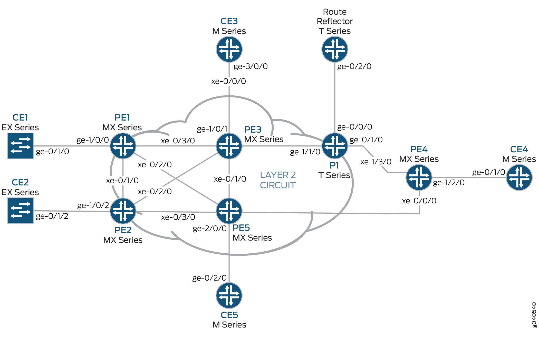
概要とトポロジー
構成
どの設定セッションでも、 コマンドを使用して commit check 設定をコミットできることを定期的に確認することをお勧めします。
この例では、設定されているルーターが次のコマンド プロンプトを使用して識別されます。
CE1カスタマーエッジ1(CE1)ルーターを識別します。PE1は、プロバイダ エッジ 1(PE1)ルーターを識別します。CE3カスタマー エッジ 3(CE3)ルーターを識別します。PE3は、プロバイダ エッジ 3(PE3)ルーターを識別します。CE5カスタマーエッジ5(CE5)ルーターを識別します。PE5は、プロバイダ エッジ 5(PE5)ルーターを識別します。
この例は、以下のセクションで構成されています。
PE および P ルーターでのプロトコルの設定
手順
この例では、すべての PE ルーターと P ルーターが IGP プロトコルとして OSPF で設定されています。MPLS、LDP、および BGP プロトコルは、 fxp.0 を除くすべてのインターフェイスで有効になっています。コアに面したインターフェイスは、MPLS アドレスと inet アドレスで有効になっています。
すべてのPEおよびPルーターをOSPFをIGPとして設定します。を除く
fxp.0すべてのインターフェイスで MPLS、LDP、BGP プロトコルを有効にします。LDP は、レイヤー 2 回線のルーター PE1 のシグナリング プロトコルとして使用されます。以下の設定スニペットは、ルーターPE1のプロトコル設定を示しています。[edit] protocols { mpls { interface all; interface fxp0.0 { disable; } } bgp { group RR { type internal; local-address 192.0.2.1; family l2vpn { signaling; } neighbor 192.0.2.7; } } ospf { traffic-engineering; area 0.0.0.0 { interface all; interface fxp0.0 { disable; } } } ldp { interface all; interface fxp0.0 { disable; } } }OSPF を IGP として PE および P ルーターを設定します。を除く
fxp.0すべてのインターフェイスで MPLS、LDP、BGP プロトコルを有効にします。BGP は、レイヤー 2 VPN のルーター PE3 上のシグナリング プロトコルとして使用されます。以下の設定スニペットは、ルーターPE3のプロトコル設定を示しています。[edit] protocols { mpls { interface all; interface fxp0.0 { disable; } } bgp { group RR { type internal; local-address 192.0.2.3; family l2vpn { signaling; } neighbor 192.0.2.7; } } ospf { traffic-engineering; area 0.0.0.0 { interface all; interface fxp0.0 { disable; } } } ldp { interface all; interface fxp0.0 { disable; } } }
手順
インターフェイスの設定
ルーターPE1で、インターフェイスカプセル化を
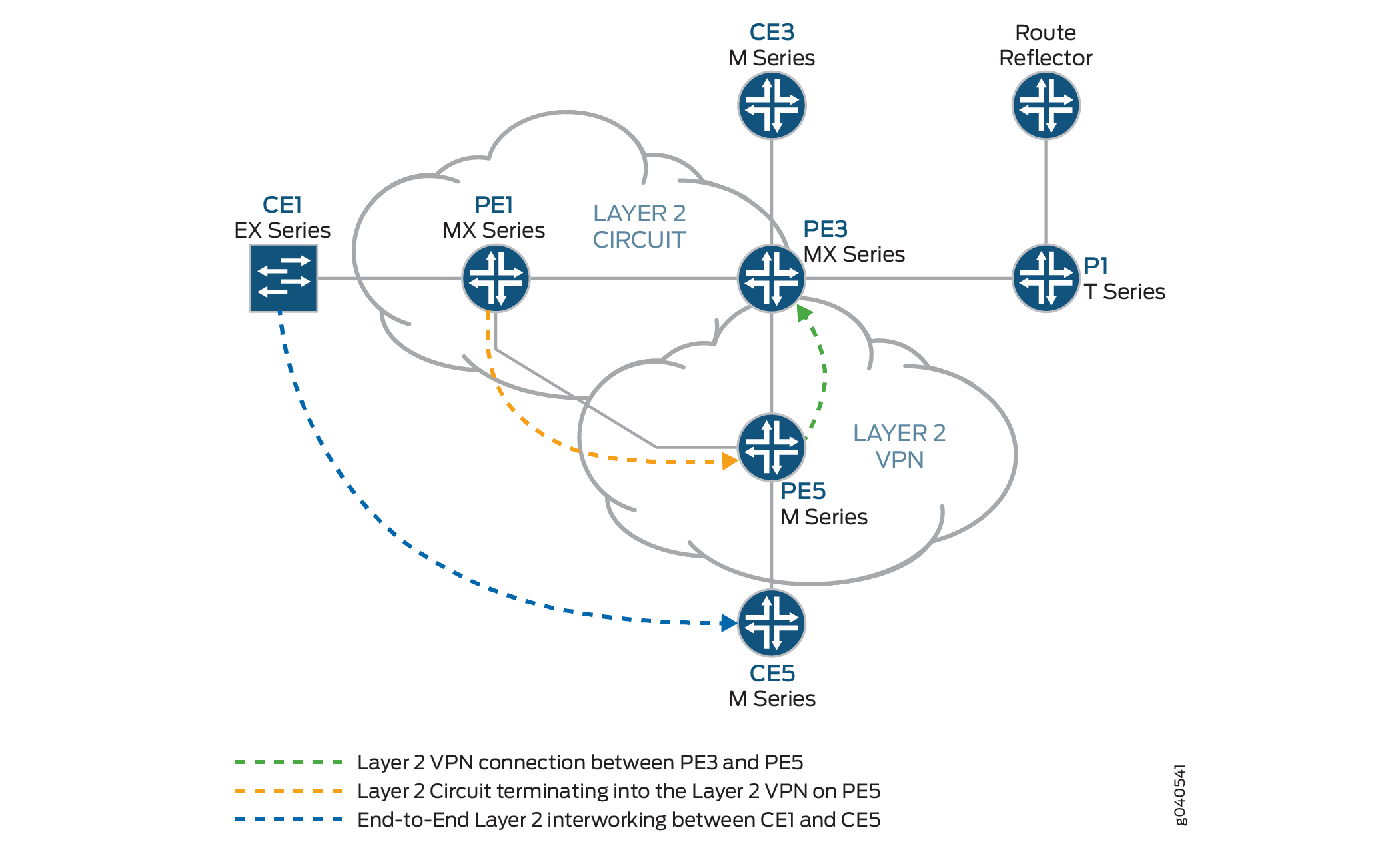
ge-1/0/0設定します。インターフェイスカプセル化を設定するには、 ステートメントをencapsulation含め、 オプションを指定しますethernet-ccc(vlan-cccカプセル化もサポートされています)。ge-1/0/0.0回線クロスコネクト機能の論理インターフェイスファミリーを設定します。論理インターフェイスファミリーを設定するには、 ステートメントをfamily含め、 オプションをccc指定します。カプセル化は、レイヤー2回線ドメインのすべてのルーターに同じ方法で設定する必要があります。[edit interfaces] ge-1/0/0 { encapsulation ethernet-ccc; unit 0 { family ccc; } } lo0 { unit 0 { family inet { address 192.0.2.1/24; } } }ルーターPE5は、インターワーキングインターフェイス を 使用して、レイヤー2回線をレイヤー2 VPNにステッチングするルーターです。ピアユニットインターフェイスの設定が、相互接続を行う理由です。
ルーターPE5では、2つの論理インターフェイスでインターフェイスを設定
iw0します。インターフェイスをiw0設定するには、 ステートメントをinterfaces含め、 をインターフェイス名に指定iw0します。ユニット0の論理インターフェイスには、 ステートメントをpeer-unit含め、論理インターフェイスをピアインターフェイスunit 1として指定します。ユニット1の論理インターフェイスには、 ステートメントをpeer-unit含め、論理インターフェイスをピアインターフェイスunit 0として指定します。[edit interfaces] iw0 { unit 0 { encapsulation ethernet-ccc; peer-unit 1; } unit 1 { encapsulation ethernet-ccc; peer-unit 0; } }ルーターPE5で、論理ループバックインターフェイスを設定します。ループバックインターフェイスは、ルーターPE1およびPE5へのターゲットLDPセッションを確立するために使用されます。
[edit interfaces]
lo0 {
    unit 0 {
        family inet {
            address 192.0.2.5/24;
        }
    }
}
手順
レイヤー 2 回線プロトコルの設定
ルーターPE1では、 ステートメントでリモートPEルーターのIPアドレスを
neighbor設定します。PE ネイバーのループバック アドレスとルーター ID は、一般にネイバーの IP アドレスです。PE ルーターに設定された最大送信単位(MTU)がリモート PE ルーターで設定された MTU と一致しない場合でも、レイヤー 2 回線を確立できるようにするには、 ステートメントをignore-mtu-mismatch含めます。[edit] protocols { l2circuit { neighbor 192.0.2.5 { interface ge-1/0/0.0 { virtual-circuit-id 100; no-control-word; ignore-mtu-mismatch; } } } }ルーターPE5で、リモートPEルーターのIPアドレスを設定します。リモート PE ルーターの IP アドレスを設定するには、 ステートメントを
neighbor含め、ルーター PE1 のループバック インターフェイスの IP アドレスを指定します。仮想回線 ID を、ネイバー ルーターの仮想回線 ID と同じに設定します。ローカルPEルーターに設定されたMTUがリモートPEルーターで設定されたMTUと一致しない場合でも、レイヤー2回線を確立できるようにするには、 ステートメントをignore-mtu-mismatch使用します。また、 ステートメントを含めることで、制御ワードの逆多重化の使用をno-control-word無効にします。[edit protocols] l2circuit { neighbor 192.0.2.1 { interface iw0.0 { virtual-circuit-id 100; no-control-word; ignore-mtu-mismatch; } } }ルーターPE5では、 階層レベルで ステートメントを
l2vpn含めてレイヤー2 VPNプロトコルを[edit routing-instances routing-instances-name protocols]設定します。インターフェイスをiw0設定するには、 ステートメントをinterfaces含め、 をインターフェイス名に指定iw0します。インターフェイスはiw0、論理インターフェイスからループしたパケットを受信するようにレイヤー2 VPNプロトコルの下でiw0.1設定されています。プロトコルはl2vpn、BGP L2VPNルーティングインスタンスで設定されたサイトCE5を備えたルーターPE5で設定されています。ルーターCE1は、ルーターPE5上のレイヤー2インターワーキング設定を介して、ルーターCE5と通信します。[edit] routing-instances { L2VPN { instance-type l2vpn; interface ge-2/0/0.0; interface iw0.1; route-distinguisher 65000:5; vrf-target target:65000:2; protocols { l2vpn { no-control-word; encapsulation-type ethernet; site CE5 { site-identifier 5; interface ge-2/0/0.0 { remote-site-id 3; } } site l2-circuit { site-identifier 6; interface iw0.1 { remote-site-id 3; } } } } } }インターフェイス設定に
iw0加えて、レイヤー2インターワーキングプロトコルをl2iw設定する必要があります。プロトコル設定l2iwがない場合、インターフェイスが存在しているかどうかiwに関係なく、レイヤー2のインターワーキングルートは形成されません。ルーターPE5で、プロトコルを設定します
l2iw。プロトコルを設定するには、 階層レベルでl2iwステートメントを[edit protocols]含めます。[edit] protocols { l2iw; }
検証
手順
ルーターPE1でのレイヤー2回線接続の検証。
ルーターPE1では、 コマンドを
show l2circuit connections使用して、ルーターPE1からルーターPE5へのレイヤー2回線が であることをUp確認します。user@PE1> show l2circuit connections Layer-2 Circuit Connections: Legend for connection status (St) EI -- encapsulation invalid NP -- interface h/w not present MM -- mtu mismatch Dn -- down EM -- encapsulation mismatch VC-Dn -- Virtual circuit Down CM -- control-word mismatch Up -- operational VM -- vlan id mismatch CF -- Call admission control failure OL -- no outgoing label IB -- TDM incompatible bitrate NC -- intf encaps not CCC/TCC TM -- TDM misconfiguration BK -- Backup Connection ST -- Standby Connection CB -- rcvd cell-bundle size bad XX -- unknown SP -- Static Pseudowire Legend for interface status Up -- operational Dn -- down Neighbor: 192.0.2.5 Interface Type St Time last up # Up trans ge-1/0/0.0(vc 100) rmtUpJan 3 22:00:49 2010 1 Remote PE: 192.0.2.5, Negotiated control-word: No Incoming label: 301328, Outgoing label: 300192 Local interface: ge-1/0/0.0, Status: Up, Encapsulation: ETHERNETルーターPE5では、 コマンドを
show l2vpn connections使用して、レイヤー2 VPN接続がUpレイヤー2回線のピアインターフェイスを使用iw0していることを確認します。user@PE5> show l2vpn connections Instance: L2VPN Local site: CE5 (5) connection-site Type St Time last up # Up trans l2-circuit (6) loc OR 3 rmtUpJan 3 22:51:12 2010 1 Remote PE: 192.0.2.3, Negotiated control-word: No Incoming label: 800258, Outgoing label: 800000 Local interface: ge-2/0/0.0, Status: Up, Encapsulation: ETHERNET Local site: l2-circuit (6) connection-site Type St Time last up # Up trans CE5 (5) loc OR 3 rmt Up Jan 3 22:56:38 2010 1 Remote PE: 192.0.2.3, Negotiated control-word: No Incoming label: 800262, Outgoing label: 800001 Local interface:iw0.1, Status:Up, Encapsulation: ETHERNET
手順
レイヤー 2 回線がレイヤー 2 VPN 接続に終了していることを確認します。
ルーターPE5では、 コマンドを
show l2circuit connections使用して、レイヤー2回線がUpインターフェイスをiw0使用していることを確認します。これは、インターフェイスをiwo.1介してレイヤー2 VPNにループされます。user@PE5> show l2circuit connections Layer-2 Circuit Connections: Neighbor: 192.0.2.1 Interface Type St Time last up # Up transiw0.0(vc 100) rmtUpJan 3 21:59:07 2010 1 Remote PE: 192.0.2.1, Negotiated control-word: No Incoming label: 300192, Outgoing label: 301328ルーターPE 5で、 コマンドを
show route table mpls.0使用して、レイヤー2回線とレイヤー2 VPNルートを検証します。以下の例では、レイヤー2回線はLDPラベル301328に関連付けされ、レイヤー2 VPNはLDPラベル800001に関連付けられています。レイヤー 2 インターワーキング ルートに使用される 2 つのiw0インターフェイスに注目してください。user@PE5>show route table mpls.0 mpls.0: 18 destinations, 20 routes (18 active, 2 holddown, 0 hidden) + = Active Route, - = Last Active, * = Both 0 *[MPLS/0] 5d 20:07:31, metric 1 Receive 1 *[MPLS/0] 5d 20:07:31, metric 1 Receive 2 *[MPLS/0] 5d 20:07:31, metric 1 Receive 299776 *[LDP/9] 2d 03:00:51, metric 1 300048 *[LDP/9] 2d 03:00:49, metric 1 > to 10.10.6.1 via xe-0/1/0.0, Pop 300048(S=0) *[LDP/9] 2d 03:00:49, metric 1 > to 10.10.6.1 via xe-0/1/0.0, Pop 300192 *[L2IW/6] 19:11:05, metric2 1 > to 10.10.6.1 via xe-0/1/0.0, Swap 800001 [L2CKT/7] 20:08:36 > via iw0.0, Pop 800258 *[L2VPN/7] 19:16:31 > via ge-2/0/0.0, Pop Offset: 4800262 *[L2IW/6] 19:11:05, metric2 1 > to 10.10.3.1 via xe-1/1/0.0, Swap 301328 [L2VPN/7] 19:11:05 > via iw0.1, Pop Offset: 4ge-2/0/0.0 *[L2VPN/7] 19:16:31, metric2 1 > to 10.10.6.1 via xe-0/1/0.0, Push 800000 Offset: -4 iw0.0 *[L2CKT/7]20:08:36, metric2 1 > to 10.10.3.1 via xe-1/1/0.0, Push301328iw0.1 *[L2VPN/7]19:11:05, metric2 1 > to 10.10.6.1 via xe-0/1/0.0, Push800001Offset: -4