例:H-VPLS BGP ベースおよび LDP ベース VPLS 相互運用の設定
この例では、マルチホーミング導入で相互運用するLDPベースのVPLSとBGPベースのVPLSの両方を使用するシナリオで、H-VPLS(階層型仮想プライベートLANサービス)を設定する方法を示しています。このシナリオは、顧客の導入環境で 2 種類の VPLS が使用されており、それらを統合する必要がある場合に便利です。もう1つの例は、ISP-AがBGPベースのVPLSを実行していて、ISP-BがLDPベースのVPLSを実行していて、2つのISPがネットワークをマージしている場合です。
要件
この例を設定する前に、デバイス初期化以外の特別な設定は必要ありません。
概要
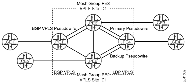
この例では、デバイス PE2 とデバイス PE3 は、BGP ベースおよび LDP ベースの VPLS 終端を持つインターネットワーキング プロバイダ エッジ(PE)ルーターとして機能しています。
この例のデバイスの役割は次のとおりです。
BGP VPLS のみ PE — デバイス PE1
LDP VPLS のみ PE — デバイス PE4
BGP-LDP VPLS PE —デバイス PE2 およびデバイス PE3
図 1 は、この例で使用したトポロジーを示しています。
 を使用した H-VPLS
デバイスPE4からデバイスPE3への疑似配線は、プライマリまたはワーキングパスです。Pseudowire デバイス PE2 はバックアップ パスです。
CLI クイック設定 は、 図 1 にすべてのデバイスの設定を示しています。セクション 手順 手順では、デバイス PE1、デバイス PE2、およびデバイス PE4 の手順について説明します。
構成
手順
CLI クイックコンフィギュレーション
この例を迅速に設定するには、以下のコマンドをコピーしてテキスト ファイルに貼り付け、改行を削除し、ネットワーク設定に合わせて必要な詳細を変更してから、 階層レベルの CLI にコマンドを [edit] コピー アンド ペーストします。
デバイスPE1
set interfaces ge-2/0/5 encapsulation ethernet-vpls
set interfaces ge-2/0/5 unit 0 description to_CE1
set interfaces ge-2/0/5 unit 0 family vpls
set interfaces fe-2/0/9 unit 0 description to_PE2
set interfaces fe-2/0/9 unit 0 family inet address 10.10.3.1/30
set interfaces fe-2/0/9 unit 0 family mpls
set interfaces fe-2/0/10 unit 0 description to_PE3
set interfaces fe-2/0/10 unit 0 family inet address 10.10.1.1/30
set interfaces fe-2/0/10 unit 0 family mpls
set interfaces lo0 unit 0 family inet address 192.0.2.1/24
set protocols mpls interface fe-2/0/10.0
set protocols mpls interface fe-2/0/9.0
set protocols ldp interface fe-2/0/10.0
set protocols ldp interface fe-2/0/9.0
set protocols ldp interface lo0.0
set protocols bgp group internal-peers type internal
set protocols bgp group internal-peers local-address 192.0.2.1
set protocols bgp group internal-peers family l2vpn signaling
set protocols bgp group internal-peers neighbor 192.0.2.2
set protocols bgp group internal-peers neighbor 192.0.2.3
set protocols ospf area 0.0.0.0 interface lo0.0 passive
set protocols ospf area 0.0.0.0 interface fe-2/0/10.0
set protocols ospf area 0.0.0.0 interface fe-2/0/9.0
set routing-instances h-vpls-PE1 instance-type vpls
set routing-instances h-vpls-PE1 interface ge-2/0/5.0
set routing-instances h-vpls-PE1 route-distinguisher 1:1
set routing-instances h-vpls-PE1 vrf-target target:1:1
set routing-instances h-vpls-PE1 protocols vpls interface ge-2/0/5.0
set routing-instances h-vpls-PE1 protocols vpls site PE1-vpls site-identifier 2
set routing-options autonomous-system 64510
デバイスPE2
set interfaces ge-2/0/6 encapsulation ethernet-vpls
set interfaces ge-2/0/6 unit 0 description to_CE2
set interfaces ge-2/0/6 unit 0 family vpls
set interfaces fe-2/0/8 unit 0 description to_PE3
set interfaces fe-2/0/8 unit 0 family inet address 10.10.4.2/30
set interfaces fe-2/0/8 unit 0 family mpls
set interfaces fe-2/0/9 unit 0 description to_PE4
set interfaces fe-2/0/9 unit 0 family inet address 10.10.5.1/30
set interfaces fe-2/0/9 unit 0 family mpls
set interfaces fe-2/0/10 unit 0 description to_PE1
set interfaces fe-2/0/10 unit 0 family inet address 10.10.3.2/30
set interfaces fe-2/0/10 unit 0 family mpls
set interfaces lo0 unit 0 family inet address 192.0.2.2/24
set protocols mpls interface fe-2/0/10.0
set protocols mpls interface fe-2/0/9.0
set protocols mpls interface fe-2/0/8.0
set protocols ldp interface fe-2/0/10.0
set protocols ldp interface fe-2/0/9.0
set protocols ldp interface fe-2/0/8.0
set protocols ldp interface lo0.0
set protocols bgp group ibgp type internal
set protocols bgp group ibgp local-address 192.0.2.2
set protocols bgp group ibgp family l2vpn signaling
set protocols bgp group ibgp neighbor 192.0.2.3
set protocols bgp group ibgp neighbor 192.0.2.1
set protocols ospf area 0.0.0.0 interface lo0.0 passive
set protocols ospf area 0.0.0.0 interface fe-2/0/10.0
set protocols ospf area 0.0.0.0 interface fe-2/0/9.0
set protocols ospf area 0.0.0.0 interface fe-2/0/8.0
set routing-instances h-vpls-PE2 instance-type vpls
set routing-instances h-vpls-PE2 interface ge-2/0/6.0
set routing-instances h-vpls-PE2 route-distinguisher 1:2
set routing-instances h-vpls-PE2 vrf-target target:1:1
set routing-instances h-vpls-PE2 protocols vpls interface ge-2/0/6.0
set routing-instances h-vpls-PE2 protocols vpls site PE2-vpls site-identifier 1
set routing-instances h-vpls-PE2 protocols vpls site PE2-vpls multi-homing
set routing-instances h-vpls-PE2 protocols vpls site PE2-vpls mesh-group h-vpls-PE2
set routing-instances h-vpls-PE2 protocols vpls vpls-id 100
set routing-instances h-vpls-PE2 protocols vpls mesh-group h-vpls-PE2 vpls-id 100
set routing-instances h-vpls-PE2 protocols vpls mesh-group h-vpls-PE2 local-switching
set routing-instances h-vpls-PE2 protocols vpls mesh-group h-vpls-PE2 neighbor 192.0.2.4
set routing-options autonomous-system 64510
デバイスPE3
set interfaces fe-2/0/8 unit 0 description to_PE2
set interfaces fe-2/0/8 unit 0 family inet address 10.10.4.1/30
set interfaces fe-2/0/8 unit 0 family mpls
set interfaces fe-2/0/9 unit 0 description to_PE4
set interfaces fe-2/0/9 unit 0 family inet address 10.10.6.1/30
set interfaces fe-2/0/9 unit 0 family mpls
set interfaces fe-2/0/10 unit 0 description to_PE1
set interfaces fe-2/0/10 unit 0 family inet address 10.10.1.2/30
set interfaces fe-2/0/10 unit 0 family mpls
set interfaces ge-2/1/3 encapsulation ethernet-vpls
set interfaces ge-2/1/3 unit 0 description to_CE3
set interfaces ge-2/1/3 unit 0 family vpls
set interfaces lo0 unit 0 family inet address 192.0.2.3/24
set protocols mpls interface fe-2/0/10.0
set protocols mpls interface fe-2/0/8.0
set protocols mpls interface fe-2/0/9.0
set protocols ldp interface fe-2/0/10.0
set protocols ldp interface fe-2/0/9.0
set protocols ldp interface fe-2/0/8.0
set protocols ldp interface lo0.0
set protocols bgp group internal-peers type internal
set protocols bgp group internal-peers local-address 192.0.2.3
set protocols bgp group internal-peers family l2vpn signaling
set protocols bgp group internal-peers neighbor 192.0.2.2
set protocols bgp group internal-peers neighbor 192.0.2.1
set protocols ospf traffic-engineering
set protocols ospf area 0.0.0.0 interface lo0.0 passive
set protocols ospf area 0.0.0.0 interface fe-2/0/10.0
set protocols ospf area 0.0.0.0 interface fe-2/0/8.0
set protocols ospf area 0.0.0.0 interface fe-2/0/9.0
set routing-instances h-vpls-PE3 instance-type vpls
set routing-instances h-vpls-PE3 interface ge-2/1/3.0
set routing-instances h-vpls-PE3 route-distinguisher 1:3
set routing-instances h-vpls-PE3 vrf-target target:1:1
set routing-instances h-vpls-PE3 protocols vpls interface ge-2/1/3.0
set routing-instances h-vpls-PE3 protocols vpls site PE3-vpls site-identifier 1
set routing-instances h-vpls-PE3 protocols vpls site PE3-vpls multi-homing
set routing-instances h-vpls-PE3 protocols vpls site PE3-vpls mesh-group h-vpls-PE3
set routing-instances h-vpls-PE3 protocols vpls vpls-id 100
set routing-instances h-vpls-PE3 protocols vpls mesh-group h-vpls-PE3 vpls-id 100
set routing-instances h-vpls-PE3 protocols vpls mesh-group h-vpls-PE3 local-switching
set routing-instances h-vpls-PE3 protocols vpls mesh-group h-vpls-PE3 neighbor 192.0.2.4
set routing-options autonomous-system 64510
デバイスPE4
set interfaces fe-2/0/9 unit 0 description to_PE3
set interfaces fe-2/0/9 unit 0 family inet address 10.10.6.2/30
set interfaces fe-2/0/9 unit 0 family mpls
set interfaces fe-2/0/10 unit 0 description to_PE2
set interfaces fe-2/0/10 unit 0 family inet address 10.10.5.2/30
set interfaces fe-2/0/10 unit 0 family mpls
set interfaces ge-2/1/7 encapsulation ethernet-vpls
set interfaces ge-2/1/7 unit 0 description to_CE4
set interfaces ge-2/1/7 unit 0 family vpls
set interfaces lo0 unit 0 family inet address 192.0.2.4/24
set protocols mpls interface fe-2/0/10.0
set protocols mpls interface fe-2/0/9.0
set protocols ldp interface fe-2/0/10.0
set protocols ldp interface fe-2/0/9.0
set protocols ldp interface lo0.0
set protocols ospf area 0.0.0.0 interface lo0.0 passive
set protocols ospf area 0.0.0.0 interface fe-2/0/10.0
set protocols ospf area 0.0.0.0 interface fe-2/0/9.0
set routing-instances ldp-vpls instance-type vpls
set routing-instances ldp-vpls interface ge-2/1/7.0
set routing-instances ldp-vpls protocols vpls vpls-id 100
set routing-instances ldp-vpls protocols vpls neighbor 192.0.2.3
set routing-instances ldp-vpls protocols vpls neighbor 192.0.2.2
デバイスCE1
set interfaces ge-2/0/8 unit 0 description to_PE1
set interfaces ge-2/0/8 unit 0 family inet address 172.16.0.1/24
set interfaces lo0 unit 0 family inet address 10.255.14.214/32
set protocols ospf area 0.0.0.0 interface lo0.0 passive
set protocols ospf area 0.0.0.0 interface ge-2/0/8.0
デバイスCE2
set interfaces ge-2/1/5 unit 0 description to_PE2
set interfaces ge-2/1/5 unit 0 family inet address 172.16.0.2/24
set interfaces lo0 unit 0 family inet address 10.255.14.215/32
set protocols ospf area 0.0.0.0 interface lo0.0 passive
set protocols ospf area 0.0.0.0 interface ge-2/1/5.0
デバイスCE3
set interfaces ge-2/0/9 unit 0 description to_PE3
set interfaces ge-2/0/9 unit 0 family inet address 172.16.0.3/24
set interfaces lo0 unit 0 family inet address 10.255.14.218/32
set protocols ospf area 0.0.0.0 interface lo0.0 passive
set protocols ospf area 0.0.0.0 interface ge-2/0/9.0
デバイスCE4
set interfaces ge-2/1/6 unit 0 description to_PE4
set interfaces ge-2/1/6 unit 0 family inet address 172.16.0.4/24
set interfaces lo0 unit 0 family inet address 10.255.14.219/32
set protocols ospf area 0.0.0.0 interface lo0.0 passive
set protocols ospf area 0.0.0.0 interface ge-2/1/6.0
手順
次の例では、設定階層内のさまざまなレベルに移動する必要があります。CLIのナビゲーションについては、 CLIユーザーガイドの設定モードでのCLIエディターの使用を参照してください。
BGPベースのVPLS PEデバイスを設定するには:
-
インターフェイスを設定します。
カスタマーエッジに接続するデバイスインターフェイスで、VPLSカプセル化とVPLSアドレスファミリーを有効にします。
コアに面したインターフェイスで、MPLS ラベルを有効にします。
[edit interfaces]
user@PE1# set ge-2/0/5 encapsulation ethernet-vpls
user@PE1# set ge-2/0/5 unit 0 description to_CE1
user@PE1# set ge-2/0/5 unit 0 family vpls
user@PE1# set fe-2/0/10 unit 0 description to_PE3
user@PE1# set fe-2/0/10 unit 0 family inet address 10.10.1.1/30
user@PE1# set fe-2/0/10 unit 0 family mpls
user@PE1# set fe-2/0/9 unit 0 description to_PE2
user@PE1# set fe-2/0/9 unit 0 family inet address 10.10.3.1/30
user@PE1# set fe-2/0/9 unit 0 family mpls
user@PE1# set lo0 unit 0 family inet address 192.0.2.1/24
-
インターフェイスでMPLSとLDPを有効にします。
他のPEデバイスに接続するMTUデバイスインターフェイスで、MPLSとLDPを設定します。
[edit protocols mpls]
user@PE1# set interface fe-2/0/10.0
user@PE1# set interface fe-2/0/9.0
[edit protocols ldp ]
user@PE1# set interface fe-2/0/10.0
user@PE1# set interface fe-2/0/9.0
user@PE1# set interface lo0.0
-
インターフェイスでルーティングを有効にします。
他のPEデバイスに接続するMTUデバイスインターフェイスで、OSPFやIS-ISなどの内部ゲートウェイプロトコル(IGP)を設定します。
[edit protocols ospf area 0.0.0.0]
user@PE1# set interface lo0.0 passive
user@PE1# set interface fe-2/0/10.0
user@PE1# set interface fe-2/0/9.0
-
レイヤー2 VPNシグナリングでBGPを設定します。
ステートメントは
l2vpn signaling、同じネットワーク層到達可能性情報(NLRI)の下で、VPLSとレイヤー2 VPNアドバタイズの両方のサポートを有効にします。内部 IBGP(IBGP)フル メッシュには、デバイス PE1、デバイス PE2、デバイス PE3 が含まれています。デバイスPE4は含まれていません。
[edit protocols bgp group internal-peers]
user@PE1# set type internal
user@PE1# set local-address 192.0.2.1
user@PE1# set family l2vpn signaling
user@PE1# set neighbor 192.0.2.2
user@PE1# set neighbor 192.0.2.3
-
VPLSルーティングインスタンスを設定します。
これはBGPベースのVPLSであるため、ルート識別、VRFターゲット、サイト名とIDが含まれます。
[edit routing-instances h-vpls-PE1]
user@PE1# set instance-type vpls
user@PE1# set interface ge-2/0/5.0
user@PE1# set route-distinguisher 1:1
user@PE1# set vrf-target target:1:1
[edit routing-instances h-vpls-PE1 protocols vpls]
user@PE1# set interface ge-2/0/5.0
user@PE1# set site PE1-vpls site-identifier 2
-
自律システム(AS)番号を設定します。
[edit routing-options]
user@PE1# set autonomous-system 64510
手順
次の例では、設定階層内のさまざまなレベルに移動する必要があります。CLIのナビゲーションについては、 CLIユーザーガイドの設定モードでのCLIエディターの使用を参照してください。
BGP-LDPベースのVPLS PEデバイスを設定するには:
インターフェイスを設定します。
カスタマーエッジに接続するPE-rデバイスインターフェイスで、VPLSカプセル化タイプとVPLSアドレスファミリーのいずれかを設定します。これにより VPLS が有効になります。
コアに面したインターフェイスで、MPLS ラベルを有効にします。
[edit interfaces]
user@PE2# set ge-2/0/6 encapsulation ethernet-vpls
user@PE2# set ge-2/0/6 unit 0 description to_CE2
user@PE2# set ge-2/0/6 unit 0 family vpls
user@PE2# set fe-2/0/10 unit 0 description to_PE1
user@PE2# set fe-2/0/10 unit 0 family inet address 10.10.3.2/30
user@PE2# set fe-2/0/10 unit 0 family mpls
user@PE2# set fe-2/0/9 unit 0 description to_PE4
user@PE2# set fe-2/0/9 unit 0 family inet address 10.10.5.1/30
user@PE2# set fe-2/0/9 unit 0 family mpls
user@PE2# set fe-2/0/8 unit 0 description to_PE3
user@PE2# set fe-2/0/8 unit 0 family inet address 10.10.4.2/30
user@PE2# set fe-2/0/8 unit 0 family mpls
user@PE2# set lo0 unit 0 family inet address 192.0.2.2/24
インターフェイスでMPLSとLDPを有効にします。
他のPEデバイスに接続するMTUデバイスインターフェイスで、MPLSとLDPを設定します。
[edit protocols mpls]
user@PE2# set interface fe-2/0/10.0
user@PE2# set interface fe-2/0/9.0
user@PE2# set interface fe-2/0/8.0
[edit protocols ldp]
user@PE2# set interface fe-2/0/10.0
user@PE2# set interface fe-2/0/9.0
user@PE2# set interface fe-2/0/8.0
user@PE2# set interface lo0.0
インターフェイスでルーティングを有効にします。
他のPEデバイスに接続するMTUデバイスインターフェイスで、OSPFやIS-ISなどの内部ゲートウェイプロトコル(IGP)を設定します。
[edit protocols ospf area 0.0.0.0]
user@PE2# set interface lo0.0 passive
user@PE2# set interface fe-2/0/10.0
user@PE2# set interface fe-2/0/9.0
user@PE2# set interface fe-2/0/8.0
[edit protocols bgp group ibgp]
user@PE2# set type internal
user@PE2# set local-address 192.0.2.2
user@PE2# set family l2vpn signaling
user@PE2# set neighbor 192.0.2.3
user@PE2# set neighbor 192.0.2.1
VPLSを設定します。
ステートメントは
vpls-id、VPLSインスタンスのLDPシグナリングを有効にします。[edit routing-instances h-vpls-PE2] user@PE2# set instance-type vpls user@PE2# set interface ge-2/0/6.0 user@PE2# set route-distinguisher 1:2 user@PE2# set vrf-target target:1:1 [edit routing-instances h-vpls-PE2 protocols vpls] user@PE2# set interface ge-2/0/6.0 user@PE2# set site PE2-vpls site-identifier 1 user@PE2# set site PE2-vpls multi-homing user@PE2# set site PE2-vpls mesh-group h-vpls-PE2 user@PE2# set vpls-id 100 user@PE2# set mesh-group h-vpls-PE2 vpls-id 100 user@PE2# set mesh-group h-vpls-PE2 local-switching user@PE2# set mesh-group h-vpls-PE2 neighbor 192.0.2.4
[edit routing-options]
user@PE2# set autonomous-system 64510
手順
次の例では、設定階層内のさまざまなレベルに移動する必要があります。CLIのナビゲーションについては、 CLIユーザーガイドの設定モードでのCLIエディターの使用を参照してください。
LDPベースのVPLS PEデバイスを設定するには:
インターフェイスを設定します。
カスタマーエッジに接続するPE-rデバイスインターフェイスで、VPLSカプセル化タイプとVPLSアドレスファミリーのいずれかを設定します。これにより VPLS が有効になります。
コアに面したインターフェイスで、MPLS ラベルを有効にします。
[edit interfaces]
user@PE4# set fe-2/0/10 unit 0 description to_PE2
user@PE4# set fe-2/0/10 unit 0 family inet address 10.10.5.2/30
user@PE4# set fe-2/0/10 unit 0 family mpls
user@PE4# set fe-2/0/9 unit 0 description to_PE3
user@PE4# set fe-2/0/9 unit 0 family inet address 10.10.6.2/30
user@PE4# set fe-2/0/9 unit 0 family mpls
user@PE4# set ge-2/1/7 encapsulation ethernet-vpls
user@PE4# set ge-2/1/7 unit 0 description to_CE4
user@PE4# set ge-2/1/7 unit 0 family vpls
user@PE4# set lo0 unit 0 family inet address 192.0.2.4/24
インターフェイスでMPLSとLDPを有効にします。
他のPEデバイスに接続するMTUデバイスインターフェイスで、MPLSとLDPを設定します。
[edit protocols mpls]
user@PE4# set interface fe-2/0/10.0
user@PE4# set interface fe-2/0/9.0
[edit protocols ldp]
user@PE4# set interface fe-2/0/10.0
user@PE4# set interface fe-2/0/9.0
user@PE4# set interface lo0.0
インターフェイスでルーティングを有効にします。
他のPEデバイスに接続するMTUデバイスインターフェイスで、OSPFやIS-ISなどの内部ゲートウェイプロトコル(IGP)を設定します。
[edit protocols ospf area 0.0.0.0]
user@PE4# set interface lo0.0 passive
user@PE4# set interface fe-2/0/10.0
user@PE4# set interface fe-2/0/9.0
VPLSを設定します。
ステートメントは
vpls-id、VPLSインスタンスのLDPシグナリングを有効にします。[edit routing-instances ldp-vpls] user@PE4# set instance-type vpls user@PE4# set interface ge-2/1/7.0 user@PE4# set protocols vpls vpls-id 100 [edit routing-instances ldp-vpls protocols vpls] user@PE4# set neighbor 192.0.2.3 user@PE4# set neighbor 192.0.2.2
結果
設定モードから、 、show routing-instancesshow protocolsおよび のコマンドをshow interfaces入力して設定をshow routing-options確認します。出力結果に意図した設定が表示されない場合は、この例の手順を繰り返して設定を修正します。
デバイスPE1
user@PE1# show interfaces
ge-2/0/5 {
    encapsulation ethernet-vpls;
    unit 0 {
        description to_CE1;
        family vpls;
    }
}
fe-2/0/9 {
}
    unit 0 {
        description to_PE2;
        family inet {
            address 10.10.3.1/30;
        }
        family mpls;
    }
}
fe-2/0/10 {
    unit 0 {
        description to_PE3;
        family inet {
            address 10.10.1.1/30;
        }
        family mpls;
    }
}
lo0 {
    unit 0 {
        family inet {
            address 192.0.2.1/24;
        }
    }
}
user@PE1# show protocols
mpls {
    interface fe-2/0/10.0;
    interface fe-2/0/9.0;
}
bgp {
    group internal-peers {
        type internal;
        local-address 192.0.2.1;
        family l2vpn {
            signaling;
        }
        neighbor 192.0.2.2;
        neighbor 192.0.2.3;
    }
}
ospf {
    area 0.0.0.0 {
        interface lo0.0 {
            passive;
        }
        interface fe-2/0/10.0;
        interface fe-2/0/9.0;
    }
}
ldp {
    interface fe-2/0/10.0;
    interface fe-2/0/9.0;
    interface lo0.0;
}
user@PE1# show routing-instances
h-vpls-PE1 {
    instance-type vpls;
    interface ge-2/0/5.0;
    route-distinguisher 1:1;
    vrf-target target:1:1;
    protocols {
        vpls {
            interface ge-2/0/5.0;
            site PE1-vpls {
                site-identifier 2;
            }
        }
    }
}
user@PE1# show routing-options
autonomous-system 64510;
デバイスPE2
user@PE2# show interfaces
ge-2/0/6 {
    encapsulation ethernet-vpls;
    unit 0 {
        description to_CE2;
        family vpls;
    }
}
fe-2/0/8 {
    unit 0 {
        description to_PE3;
        family inet {
            address 10.10.4.2/30;
        }
        family mpls;
    }
}
fe-2/0/9 {
    unit 0{
        description to_PE4;
        family inet {
            address 10.10.5.1/30;
        }
        family mpls;
    }
}
fe-2/0/10 {
    unit 0 {
        description to_PE1;
        family inet {
            address 10.10.3.2/30;
        }
        family mpls;
    }
}
lo0 {
    unit 0 {
        family inet {
            address 192.0.2.2/24;
        }
    }
}
user@PE2# show protocols
mpls {
    interface fe-2/0/10.0;
    interface fe-2/0/9.0;
    interface fe-2/0/8.0;
}
bgp {
    group ibgp {
        type internal;
        local-address 192.0.2.2;
        family l2vpn {
            signaling;
        }
        neighbor 192.0.2.3;
        neighbor 192.0.2.1;
    }
}
ospf {
    area 0.0.0.0 {
        interface lo0.0 {
            passive;
        }
        interface fe-2/0/10.0;
        interface fe-2/0/9.0;
        interface fe-2/0/8.0;
    }
}
ldp {
    interface fe-2/0/10.0;
    interface fe-2/0/9.0;
    interface fe-2/0/8.0;
    interface lo0.0;
}
user@PE2# show routing-instances
h-vpls-PE2 {
    instance-type vpls;
    interface ge-2/0/6.0;
    route-distinguisher 1:2;
    vrf-target target:1:1;
    protocols {
        vpls {
            interface ge-2/0/6.0;
            site PE2-vpls {
                site-identifier 1;
                multi-homing;
                mesh-group h-vpls-PE2;
            }
            vpls-id 100;
            mesh-group h-vpls-PE2 {
                vpls-id 100;
                local-switching;
                neighbor 192.0.2.4;
            }
        }
    }
}
user@PE2# show routing-options
autonomous-system 64510;
デバイスPE4
user@PE4# show interfaces
ge-2/1/7 {
    encapsulation ethernet-vpls;
    unit 0 {
        description to_CE4;
        family vpls;
    }
}
fe-2/0/9 {
    unit 0 {
        description to_PE3;
        family inet {
            address 10.10.6.2/30;
        }
        family mpls;
    }
}
fe-2/0/10 {
    unit 0 {
        description to_PE2;
        family inet {
            address 10.10.5.2/30;
        }
        family mpls;
    }
}
lo0 {
    unit 0 {
        family inet {
            address 192.0.2.4/24;
        }
    }
}
user@PE4# show protocols
mpls {
    interface fe-2/0/9.0;
    interface fe-2/0/10.0;
}
ospf {
    area 0.0.0.0 {
        interface lo0.0 {
            passive;
        }
        interface fe-2/0/9.0;
        interface fe-2/0/10.0;
    }
}
ldp {
    interface fe-2/0/10.0;
    interface fe-2/0/9.0;
    interface lo0.0;
}
user@PE4# show routing-instances
ldp-vpls {
    instance-type vpls;
    interface ge-2/1/7.0;
    protocols {
        vpls {
            vpls-id 100;
            neighbor 192.0.2.3;
            neighbor 192.0.2.2;
        }
    }
}
デバイスの設定が完了したら、設定モードから を入力します commit 。
検証
設定が正しく機能していることを確認します。BGP-LDP VPLS を使用したマルチホーミング シナリオでは、LDP 擬似配線はバックアップ PE(デバイス PE2)のダウン状態になります。一方、LDP のみの VPLS PE(デバイス PE4)では、プライマリおよびバックアップ BGP-LDP PE デバイスへの疑似配線はアップ状態です。
- VPLS接続の検証
- アクティブ擬似回線からバックアップ擬似回線へのスイッチの手動トリガー
- 接続性の確認
- BGPレイヤー2 VPNルーティングテーブルの確認
- レイヤー 2 回線ルーティング テーブルの確認
VPLS接続の検証
目的
VPLS接続が期待どおりに機能していることを確認します。
アクション
動作モードから、 コマンドを show vpls connections 入力します。
user@PE1> show vpls connections
Layer-2 VPN connections:

Legend for connection status (St)
EI -- encapsulation invalid      NC -- interface encapsulation not CCC/TCC/VPLS
EM -- encapsulation mismatch     WE -- interface and instance encaps not same
VC-Dn -- Virtual circuit down    NP -- interface hardware not present
CM -- control-word mismatch      -> -- only outbound connection is up
CN -- circuit not provisioned    <- -- only inbound connection is up
OR -- out of range               Up -- operational
OL -- no outgoing label          Dn -- down
LD -- local site signaled down   CF -- call admission control failure
RD -- remote site signaled down  SC -- local and remote site ID collision
LN -- local site not designated  LM -- local site ID not minimum designated
RN -- remote site not designated RM -- remote site ID not minimum designated
XX -- unknown connection status  IL -- no incoming label
MM -- MTU mismatch               MI -- Mesh-Group ID not available
BK -- Backup connection          ST -- Standby connection
PF -- Profile parse failure      PB -- Profile busy
RS -- remote site standby        SN -- Static Neighbor
LB -- Local site not best-site   RB -- Remote site not best-site
VM -- VLAN ID mismatch

Legend for interface status
Up -- operational
Dn -- down

Instance: h-vpls-PE1
  Local site: PE1-vpls (2)
    connection-site           Type  St     Time last up          # Up trans
    1                         rmt   Up     Oct 16 16:52:27 2012           1
      Remote PE: 192.0.2.2, Negotiated control-word: No
      Incoming label: 800016, Outgoing label: 800009
      Local interface: vt-2/0/10.51380738, Status: Up, Encapsulation: VPLS
        Description: Intf - vpls h-vpls-PE1 local site 2 remote site 1
user@PE2> show vpls connections
Layer-2 VPN connections:

Legend for connection status (St)
EI -- encapsulation invalid      NC -- interface encapsulation not CCC/TCC/VPLS
EM -- encapsulation mismatch     WE -- interface and instance encaps not same
VC-Dn -- Virtual circuit down    NP -- interface hardware not present
CM -- control-word mismatch      -> -- only outbound connection is up
CN -- circuit not provisioned    <- -- only inbound connection is up
OR -- out of range               Up -- operational
OL -- no outgoing label          Dn -- down
LD -- local site signaled down   CF -- call admission control failure
RD -- remote site signaled down  SC -- local and remote site ID collision
LN -- local site not designated  LM -- local site ID not minimum designated
RN -- remote site not designated RM -- remote site ID not minimum designated
XX -- unknown connection status  IL -- no incoming label
MM -- MTU mismatch               MI -- Mesh-Group ID not available
BK -- Backup connection          ST -- Standby connection
PF -- Profile parse failure      PB -- Profile busy
RS -- remote site standby        SN -- Static Neighbor
LB -- Local site not best-site   RB -- Remote site not best-site
VM -- VLAN ID mismatch

Legend for interface status
Up -- operational
Dn -- down

Instance: h-vpls-PE2
  BGP-VPLS State
  Local site: PE2-vpls (1)
    connection-site           Type  St     Time last up          # Up trans
    1                         rmt   RN
    2                         rmt   Up     Oct 16 17:12:31 2012           1
      Remote PE: 192.0.2.1, Negotiated control-word: No
      Incoming label: 800257, Outgoing label: 800000
      Local interface: vt-2/0/10.118489089, Status: Up, Encapsulation: VPLS
        Description: Intf - vpls h-vpls-PE2 local site 1 remote site 2
  LDP-VPLS State
  VPLS-id: 100
  Mesh-group connections: h-vpls-PE2
    Neighbor                  Type  St     Time last up          # Up trans
    192.0.2.4(vpls-id 100)      rmt   Up     Oct 16 17:12:30 2012           1
      Remote PE: 192.0.2.4, Negotiated control-word: No
      Incoming label: 800000, Outgoing label: 800001
      Negotiated PW status TLV: No
      Local interface: vt-2/0/10.118489088, Status: Up, Encapsulation: ETHERNET
        Description: Intf - vpls h-vpls-PE2 neighbor 192.0.2.4 vpls-id 100
user@PE3> show vpls connections
Layer-2 VPN connections:

Legend for connection status (St)
EI -- encapsulation invalid      NC -- interface encapsulation not CCC/TCC/VPLS
EM -- encapsulation mismatch     WE -- interface and instance encaps not same
VC-Dn -- Virtual circuit down    NP -- interface hardware not present
CM -- control-word mismatch      -> -- only outbound connection is up
CN -- circuit not provisioned    <- -- only inbound connection is up
OR -- out of range               Up -- operational
OL -- no outgoing label          Dn -- down
LD -- local site signaled down   CF -- call admission control failure
RD -- remote site signaled down  SC -- local and remote site ID collision
LN -- local site not designated  LM -- local site ID not minimum designated
RN -- remote site not designated RM -- remote site ID not minimum designated
XX -- unknown connection status  IL -- no incoming label
MM -- MTU mismatch               MI -- Mesh-Group ID not available
BK -- Backup connection          ST -- Standby connection
PF -- Profile parse failure      PB -- Profile busy
RS -- remote site standby        SN -- Static Neighbor
LB -- Local site not best-site   RB -- Remote site not best-site
VM -- VLAN ID mismatch

Legend for interface status
Up -- operational
Dn -- down

Instance: h-vpls-PE3
  BGP-VPLS State
  Local site: PE3-vpls (1)
    connection-site           Type  St     Time last up          # Up trans
    1                         rmt   LN
    2                         rmt   LN
  LDP-VPLS State
  VPLS-id: 100
  Mesh-group connections: h-vpls-PE3
    Neighbor                  Type  St     Time last up          # Up trans
    192.0.2.4(vpls-id 100)      rmt   LN
user@PE4> show vpls connections
Layer-2 VPN connections:

Legend for connection status (St)
EI -- encapsulation invalid      NC -- interface encapsulation not CCC/TCC/VPLS
EM -- encapsulation mismatch     WE -- interface and instance encaps not same
VC-Dn -- Virtual circuit down    NP -- interface hardware not present
CM -- control-word mismatch      -> -- only outbound connection is up
CN -- circuit not provisioned    <- -- only inbound connection is up
OR -- out of range               Up -- operational
OL -- no outgoing label          Dn -- down
LD -- local site signaled down   CF -- call admission control failure
RD -- remote site signaled down  SC -- local and remote site ID collision
LN -- local site not designated  LM -- local site ID not minimum designated
RN -- remote site not designated RM -- remote site ID not minimum designated
XX -- unknown connection status  IL -- no incoming label
MM -- MTU mismatch               MI -- Mesh-Group ID not available
BK -- Backup connection          ST -- Standby connection
PF -- Profile parse failure      PB -- Profile busy
RS -- remote site standby        SN -- Static Neighbor
LB -- Local site not best-site   RB -- Remote site not best-site
VM -- VLAN ID mismatch

Legend for interface status
Up -- operational
Dn -- down

Instance: ldp-vpls
  VPLS-id: 100
    Neighbor                  Type  St     Time last up          # Up trans
    192.0.2.2(vpls-id 100)      rmt   Up     Oct 16 17:12:23 2012           1
      Remote PE: 192.0.2.2, Negotiated control-word: No
      Incoming label: 800001, Outgoing label: 800000
      Negotiated PW status TLV: No
      Local interface: vt-2/0/10.17825793, Status: Up, Encapsulation: ETHERNET
        Description: Intf - vpls ldp-vpls neighbor 192.0.2.2 vpls-id 100
    192.0.2.3(vpls-id 100)      rmt   Up     Oct 16 17:12:20 2012           1
      Remote PE: 192.0.2.3, Negotiated control-word: No
      Incoming label: 800000, Outgoing label: 800000
      Negotiated PW status TLV: No
      Local interface: vt-2/0/10.17825792, Status: Up, Encapsulation: ETHERNET
        Description: Intf - vpls ldp-vpls neighbor 192.0.2.3 vpls-id 100
意味
デバイスPE1では、デバイスPE2へのBGP-VPLS接続が立ち上がっています。安定した状態では、デバイスPE2はプライマリルーターであり、すべての疑似回線が終端しています。CE1 から PE1、PE2、PE4 から CE4 へのトラフィック フロー。
デバイスPE2では、デバイスPE1へのBGP-VPLS接続が立ち上がっています。デバイスPE3への接続はRN状態です。デバイスPE4へのLDP-VPLS接続が稼働しています。
デバイス PE3 では、すべての VPLS 接続が LN 状態になっています。これは、デバイス PE3 がバックアップであるためです。
デバイスPE4、LDP専用VPLSルーター、デバイスPE2へのプライマリ擬似回線、デバイスPE3へのバックアップ擬似回線はアップ状態です。
アクティブ擬似回線からバックアップ擬似回線へのスイッチの手動トリガー
目的
デバイス PE2 が利用できなくなった場合、トラフィック フローがデバイス PE3 に移行することを確認します。
アクション
デバイスPE2で、インターフェイスを無効にします。
user@PE2# deactivate interfaces
user@PE2# commit
show vpls connectionsすべての PE デバイスで コマンドを再実行してください。user@PE1> show vpls connections Layer-2 VPN connections: Legend for connection status (St) EI -- encapsulation invalid NC -- interface encapsulation not CCC/TCC/VPLS EM -- encapsulation mismatch WE -- interface and instance encaps not same VC-Dn -- Virtual circuit down NP -- interface hardware not present CM -- control-word mismatch -> -- only outbound connection is up CN -- circuit not provisioned <- -- only inbound connection is up OR -- out of range Up -- operational OL -- no outgoing label Dn -- down LD -- local site signaled down CF -- call admission control failure RD -- remote site signaled down SC -- local and remote site ID collision LN -- local site not designated LM -- local site ID not minimum designated RN -- remote site not designated RM -- remote site ID not minimum designated XX -- unknown connection status IL -- no incoming label MM -- MTU mismatch MI -- Mesh-Group ID not available BK -- Backup connection ST -- Standby connection PF -- Profile parse failure PB -- Profile busy RS -- remote site standby SN -- Static Neighbor LB -- Local site not best-site RB -- Remote site not best-site VM -- VLAN ID mismatch Legend for interface status Up -- operational Dn -- down Instance: h-vpls-PE1 Local site: PE1-vpls (2) connection-site Type St Time last up # Up trans 1 rmt Up Oct 17 12:24:01 2012 2 Remote PE: 192.0.2.3, Negotiated control-word: No Incoming label: 800000, Outgoing label: 800257 Local interface: vt-2/0/10.84934656, Status: Up, Encapsulation: VPLS Description: Intf - vpls h-vpls-PE1 local site 2 remote site 1user@PE2> show vpls connections Layer-2 VPN connections: Legend for connection status (St) EI -- encapsulation invalid NC -- interface encapsulation not CCC/TCC/VPLS EM -- encapsulation mismatch WE -- interface and instance encaps not same VC-Dn -- Virtual circuit down NP -- interface hardware not present CM -- control-word mismatch -> -- only outbound connection is up CN -- circuit not provisioned <- -- only inbound connection is up OR -- out of range Up -- operational OL -- no outgoing label Dn -- down LD -- local site signaled down CF -- call admission control failure RD -- remote site signaled down SC -- local and remote site ID collision LN -- local site not designated LM -- local site ID not minimum designated RN -- remote site not designated RM -- remote site ID not minimum designated XX -- unknown connection status IL -- no incoming label MM -- MTU mismatch MI -- Mesh-Group ID not available BK -- Backup connection ST -- Standby connection PF -- Profile parse failure PB -- Profile busy RS -- remote site standby SN -- Static Neighbor LB -- Local site not best-site RB -- Remote site not best-site VM -- VLAN ID mismatch Legend for interface status Up -- operational Dn -- down Instance: h-vpls-PE2 BGP-VPLS State Local site: PE2-vpls (1) LDP-VPLS State VPLS-id: 100 Mesh-group connections: h-vpls-PE2 Neighbor Type St Time last up # Up trans 192.0.2.4(vpls-id 100) rmt OLuser@PE3> show vpls connections Layer-2 VPN connections: Legend for connection status (St) EI -- encapsulation invalid NC -- interface encapsulation not CCC/TCC/VPLS EM -- encapsulation mismatch WE -- interface and instance encaps not same VC-Dn -- Virtual circuit down NP -- interface hardware not present CM -- control-word mismatch -> -- only outbound connection is up CN -- circuit not provisioned <- -- only inbound connection is up OR -- out of range Up -- operational OL -- no outgoing label Dn -- down LD -- local site signaled down CF -- call admission control failure RD -- remote site signaled down SC -- local and remote site ID collision LN -- local site not designated LM -- local site ID not minimum designated RN -- remote site not designated RM -- remote site ID not minimum designated XX -- unknown connection status IL -- no incoming label MM -- MTU mismatch MI -- Mesh-Group ID not available BK -- Backup connection ST -- Standby connection PF -- Profile parse failure PB -- Profile busy RS -- remote site standby SN -- Static Neighbor LB -- Local site not best-site RB -- Remote site not best-site VM -- VLAN ID mismatch Legend for interface status Up -- operational Dn -- down Instance: h-vpls-PE3 BGP-VPLS State Local site: PE3-vpls (1) connection-site Type St Time last up # Up trans 2 rmt Up Oct 17 12:24:01 2012 1 Remote PE: 192.0.2.1, Negotiated control-word: No Incoming label: 800257, Outgoing label: 800000 Local interface: vt-2/0/10.135266304, Status: Up, Encapsulation: VPLS Description: Intf - vpls h-vpls-PE3 local site 1 remote site 2 LDP-VPLS State VPLS-id: 100 Mesh-group connections: h-vpls-PE3 Neighbor Type St Time last up # Up trans 192.0.2.4(vpls-id 100) rmt Up Oct 17 12:24:02 2012 1 Remote PE: 192.0.2.4, Negotiated control-word: No Incoming label: 800000, Outgoing label: 800000 Negotiated PW status TLV: No Local interface: vt-2/0/10.135266305, Status: Up, Encapsulation: ETHERNET Description: Intf - vpls h-vpls-PE3 neighbor 192.0.2.4 vpls-id 100user@PE4> show vpls connections Layer-2 VPN connections: Legend for connection status (St) EI -- encapsulation invalid NC -- interface encapsulation not CCC/TCC/VPLS EM -- encapsulation mismatch WE -- interface and instance encaps not same VC-Dn -- Virtual circuit down NP -- interface hardware not present CM -- control-word mismatch -> -- only outbound connection is up CN -- circuit not provisioned <- -- only inbound connection is up OR -- out of range Up -- operational OL -- no outgoing label Dn -- down LD -- local site signaled down CF -- call admission control failure RD -- remote site signaled down SC -- local and remote site ID collision LN -- local site not designated LM -- local site ID not minimum designated RN -- remote site not designated RM -- remote site ID not minimum designated XX -- unknown connection status IL -- no incoming label MM -- MTU mismatch MI -- Mesh-Group ID not available BK -- Backup connection ST -- Standby connection PF -- Profile parse failure PB -- Profile busy RS -- remote site standby SN -- Static Neighbor LB -- Local site not best-site RB -- Remote site not best-site VM -- VLAN ID mismatch Legend for interface status Up -- operational Dn -- down Instance: ldp-vpls VPLS-id: 100 Neighbor Type St Time last up # Up trans 192.0.2.2(vpls-id 100) rmt OL 192.0.2.3(vpls-id 100) rmt Up Oct 16 17:12:20 2012 1 Remote PE: 192.0.2.3, Negotiated control-word: No Incoming label: 800000, Outgoing label: 800000 Negotiated PW status TLV: No Local interface: vt-2/0/10.17825792, Status: Up, Encapsulation: ETHERNET Description: Intf - vpls ldp-vpls neighbor 192.0.2.3 vpls-id 100
意味
デバイスPE1では、デバイスPE3へのBGP-VPLS接続が立ち上がっています。CE1 から PE1、PE3、PE4 から CE4 へのトラフィック フロー。
デバイスPE2では、デバイスPE1へのBGP-VPLS接続がOL状態になっています。
デバイスPE3では、すべてのVPLS接続が稼働しています。
デバイス PE4 では、デバイス PE2 への VPLS 接続は OL 状態です。デバイスPE3へのVPLS接続が稼働しています。
デバイスPE2上のインターフェイスを再活性化すると、接続は以前の状態とトラフィックフローに戻ります。
接続性の確認
目的
デバイス CE1 がデバイス CE4 に ping を実行できることを確認します。
アクション
user@CE1> ping 10.255.14.219

PING 10.255.14.219 (10.255.14.219): 56 data bytes
64 bytes from 10.255.14.219: icmp_seq=0 ttl=64 time=1.149 ms
64 bytes from 10.255.14.219: icmp_seq=1 ttl=64 time=0.779 ms
^C
--- 10.255.14.219 ping statistics ---
2 packets transmitted, 2 packets received, 0% packet loss
round-trip min/avg/max/stddev = 0.779/0.964/1.149/0.185 ms
意味
出力は、VPLSが動作していることを示しています。
BGPレイヤー2 VPNルーティングテーブルの確認
目的
VPLSルートがBGPから学習されていることを確認します。
アクション
user@PE1> show route table bgp.l2vpn.0
bgp.l2vpn.0: 1 destinations, 1 routes (1 active, 0 holddown, 0 hidden)
+ = Active Route, - = Last Active, * = Both

1:3:1:1/96
                   *[BGP/170] 20:00:11, localpref 100, from 192.0.2.3
                      AS path: I, validation-state: unverified
                    > to 10.10.1.2 via fe-2/0/10.0

user@PE3> show route table bgp.l2vpn.0
bgp.l2vpn.0: 1 destinations, 1 routes (1 active, 0 holddown, 0 hidden)
+ = Active Route, - = Last Active, * = Both

1:1:2:1/96
                   *[BGP/170] 20:00:11, localpref 100, from 192.0.2.1
                      AS path: I, validation-state: unverified
                    > to 10.10.1.1 via fe-2/0/10.0
レイヤー 2 回線ルーティング テーブルの確認
目的
VPLSルートがLDPから学習されていることを確認します。
アクション
user@PE3> show route table l2circuit.0
l2circuit.0: 2 destinations, 2 routes (2 active, 0 holddown, 0 hidden)
+ = Active Route, - = Last Active, * = Both

192.0.2.4:NoCtrlWord:5:100:Local/96
                   *[VPLS/7] 01:30:11, metric2 1
                    > to 10.10.6.2 via fe-2/0/9.0
192.0.2.4:NoCtrlWord:5:100:Remote/96
                   *[LDP/9] 20:41:57
                      Discard
user@PE4> show route table bgp.l2vpn.0
l2circuit.0: 3 destinations, 3 routes (2 active, 0 holddown, 1 hidden)
+ = Active Route, - = Last Active, * = Both

192.0.2.3:NoCtrlWord:5:100:Local/96
                   *[VPLS/7] 20:42:51, metric2 1
                    > to 10.10.6.1 via fe-2/0/9.0
192.0.2.3:NoCtrlWord:5:100:Remote/96
                   *[LDP/9] 20:41:57
                      Discard