このページの内容
例:マルチセグメント擬似回線の設定
この例では、ステッチングプロバイダエッジ(S-PE)デバイスがBGPによって自動的かつ動的に検出され、疑似配線がFEC 129を使用してLDPによってシグナリングされる動的マルチセグメント擬似配線(MS-PW)を設定する方法を示します。この配置では、S-PEでのプロビジョニングが最小限必要であるため、基盤となるシグナリングプロトコルとしてLDPを使用しながら、静的に設定されたレイヤー2回線に関連する設定負担が軽減されます。
要件
この例では、以下のハードウェアおよびソフトウェアコンポーネントを使用しています。
M Seriesマルチサービスエッジルーター、MXシリーズ 5Gユニバーサルルーティングプラットフォーム、T Seriesコアルーター、またはPTXシリーズパケットトランスポートルーターの組み合わせが可能な6台のルーター。
終端PE(T-PE)として設定された 2 つのリモート PE デバイス。
2つのS-PEを次のように設定:
ルートリフレクタ(エリア間構成の場合)
AS間設定の場合のAS境界ルーターまたはルートリフレクター。
すべてのデバイスで実行されている Junos OS リリース 13.3 以降。
始める前に:
デバイスインターフェイスを設定します。
OSPFまたはその他のIGPプロトコルを設定します。
BGPを設定します。
LDPを設定します。
MPLSを設定します。
概要
Junos OSリリース13.3以降、MPLSパケットスイッチネットワーク(PSN)でLDPシグナリングとBGP自動検出を備えたFEC 129を使用してMS-PWを設定できます。MS-PW機能は、T-PEデバイスからping、traceroute、BFDなどのOAM(運用、管理、管理)機能も提供します。
MS-PWでS-PEの自動検出を有効にするには、[edit protocols bgp group group-name family l2vpn]階層レベルでauto-discovery-mspwステートメントを含めます。
family l2vpn {
    auto-discovery-mspw;
}
S-PEの自動選択とMS-PWの動的セットアップは、BGPに大きく依存しています。FEC 129疑似回線がS-PEを自動検出するために構築されたネットワーク層到達可能性情報(NLRI)BGP、MS-PW NLRI[draft-ietf-pwe3-dynamic-ms-pw-15.txt]と呼ばれています。MS-PW NLRIは、基本的にRD(ルート識別子)とSAII(FEC 129送信元添付識別子)で構成されるプレフィックスです。これはBGP-AD(BGP自動検出)ルートと呼ばれ、 RD:SAIIとしてエンコードされます。
タイプ2 AIIでプロビジョニングされたT-PEのみが、それぞれ独自のMS-PW NLRIを開始します。タイプ 2 AII は世界的に一意であるため、MS-PW NLRI を使用して、タイプ 2 AII がプロビジョニングされている PE デバイスを識別します。タイプ 1 AII とタイプ 2 AII の違いにより、MS-PW をサポートするために、新しいアドレス ファミリー インジケーター(AFI)と後続のアドレス ファミリー識別子(SAFI)を BGP で定義する必要があります。MS-PW NLRI の識別に使用される提案された AFI と SAFI 値のペアは、それぞれ 25 と 6 です (IANA 割り当て保留中)。
AFIおよびSAFI値はS-PEの自動検出をサポートしており、ルートを発信するT-PEとシグナリングに参加するS-PEの両方で設定する必要があります。
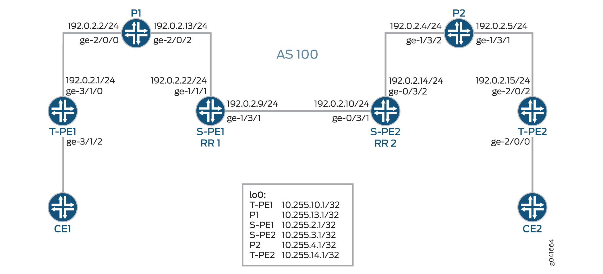
図1 は、2つのリモートPEルーター(T-PE1とT-PE2)間のエリア間MS-PW設定を示しています。プロバイダ(P)ルーターはP1とP2、S-PEルーターはS-PE1とS-PE2です。MS-PWはT-PE1とT-PE2の間で確立され、すべてのデバイスが同じAS—AS 100に属します。S-PE1 と S-PE2 は同じ AS に属しているため、ルート リフレクタとして機能し、それぞれ RR 1 および RR 2 とも呼ばれます。
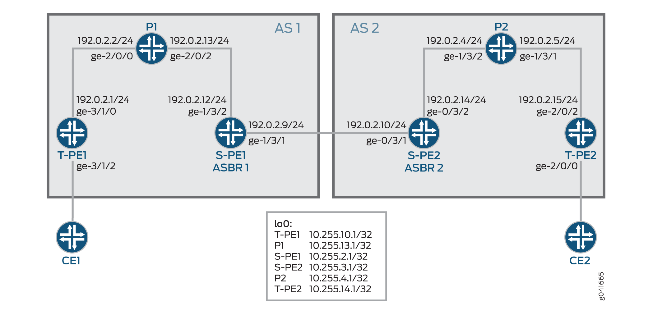
図2 は、AS間MS-PWの設定を示しています。MS-PW は T-PE1 と T-PE2 の間で確立され、T-PE1、P1、S-PE1 は AS 1 に、S-PE2、P2、T-PE2 は AS 2 に属します。S-PE1とS-PE2は異なるASに属しているため、ASBRルーターとして設定され、それぞれASBR 1およびASBR 2とも呼ばれます。
次のセクションでは、エリア間およびAS間シナリオでMS-PWを確立する方法について説明します。
Minimum Configuration Requirements on S-PE
SS-PWの両端を動的に検出し、T-LDPセッションを動的に設定するには、以下のものが必要です。
エリア間MS-PWでは、各S-PEがABRとBGPの両方のルートリフレクタの役割を果たします。
図 1 に示すように、エリア間のケースでは、S-PE は BGP ルートリフレクタの役割を果たし、BGP-AD ルートをクライアントに反映します。1つのT-PEによってアドバタイズされたBGP-ADルートは、最終的にリモートT-PEに到達します。各S-PEでネクストホップ自己が設定されているため、BGP-ADルートを受信したS-PEまたはT-PEは、BGPネクストホップを介してローカルASまたはローカルエリアでBGP-ADをアドバタイズしているS-PEを常に検出できます。
AS間MS-PWでは、各S-PEがASBRまたはBGPルートリフレクタの役割を果たします。
MS-PW では、2 つの T-PE がそれぞれ BGP-AD ルートを開始します。S-PEがT-PEとのIBGPセッションまたは通常のBGP-RRのいずれかを介してBGP-ADルートを受信すると、 図2に示すように、AS間ケースでは1つ以上のEBGPピアにBGP-ADルートを再アドバタイズする前にネクストホップセルフを設定します。
各S-PEは、MS-PWのBGP-ADルートを再アドバタイズまたは反映する際に、next-hop-selfを設定する必要があります。
Active and Passive Role of T-PE
同じS-PEのセットが両方向のMS-PWに使用されるようにするために、2つのT-PEはFEC 129シグナリングに関して異なる役割を果たします。これは、各S-PEがMS-PWに対して動的に選択されたときに、T-PE1とT-PE2によって異なるパスが選択されないようにするためです。
FEC 129を使用してMS-PWがシグナリングされると、各T-PEは独立してMS-PWのシグナリングを開始する場合があります。シグナリング手順では、異なるS-PEを介してMS-PWの各方向を設定しようとする場合があります。
このような状況を回避するには、一方の T-PE が疑似配線シグナリング(アクティブ ロール)を開始し、もう一方の T-PE は LDP ラベル マッピングの受信を待ってから、それぞれの疑似配線 LDP ラベル マッピング メッセージ(パッシブ ロール)を送信する必要があります。MS-PWパスが動的に配置されている場合、特定のMS-PWに対してシグナリングが開始される前に、アクティブT-PE(ソースT-PE)とパッシブT-PE(ターゲットT-PE)を識別する必要があります。どのT-PEが能動的な役割を担うかの判断は、SAII値に基づいて行われ、SAII値が大きいT-PEが能動的な役割を果たす。
この例では、T-PE1とT-PE2のSAII値はそれぞれ 800:800:800 と 700:700:700です。T-PE1はSAII値が高いため、能動的な役割を、T-PE2はパッシブの役割を引き受けます。
Directions for Establishing an MS-PW
S-PE が MS-PW を設定するために使用する指示は次のとおりです。
転送方向—アクティブT-PEからパッシブT-PEへ。
この方向では、S-PEはBGP-ADルートルックアップを実行して、ラベルマッピングメッセージを送信するネクストホップS-PEを決定します。
逆方向—パッシブT-PEからアクティブT-PEへ。
この方向では、ラベルマッピングメッセージはT-PEから受信され、ステッチルートはS-PEにインストールされるため、S-PEはBGP-ADルート検索を実行しません。
この例では、T-PE1 から T-PE2 への転送方向に MS-PW が確立されています。MS-PWをT-PE2からT-PE1に配置すると、MS-PWは逆方向に確立されます。
Autodiscovery and Dynamic Selection of S-PE
新しいAFIおよびSAFI値がBGPで定義され、タイプ2 AIIに基づくMS-PWをサポートします。この新しいアドレスファミリーは、S-PEの自動検出をサポートしています。このアドレスファミリーは、TPEとSPEの両方で設定する必要があります。
レイヤー2 VPNコンポーネントは、転送方向にMS-PWに沿って使用する次のS-PEを動的に選択します。
転送方向では、BGPがアドバタイズするBGP-ADルートとLDPから送信された疑似回線FEC情報に基づいて、次のBGP-PEの選択が行われます。BGP-ADルートは、逆方向のパッシブT-PE(T-PE2)によって開始され、疑似回線FEC情報は、転送方向のアクティブT-PE(T-PE1)からLDPによって送信されます。
逆方向では、次のS-PE(S-PE2)またはアクティブなT-PE(T-PE1)は、転送方向で疑似配線を設定するために使用したS-PE(S-PE1)を検索して取得されます。
Provisioning a T-PE
FEC 129 タイプ 2 AII をサポートするには、T-PE はリモート T-PE の IP アドレス、グローバル ID、およびアタッチメント回線 ID を設定する必要があります。 使用するS-PEのセットがT-PEで明示的に指定されている明示的なパスはサポートされていません。これにより、各S-PEにタイプ2 AIIをプロビジョニングする必要がなくなります。
Stitching an MS-PW
S-PE は、受信したラベルマッピングメッセージを次の S-PE に転送する前に、以下の MPLS ラベル操作を実行します。
MPLS トンネルラベルをポップします。
VCラベルをポップします。
新しいVCラベルをプッシュします。
次のセグメントに使用される MPLS トンネルラベルをプッシュします。
Establishing an MS-PW
必要な設定が完了すると、以下の方法でMS-PWが確立されます。
SAII値は、BGPを使用してT-PE1とT-PE2の間で交換されます。
T-PE1は、より高いSAII値で設定されているため、アクティブなT-PEロールを引き継ぎます。T-PE2 はパッシブ T-PE になります。
T-PE1は、T-PE2によって発信されたBGP-ADルートを受信します。受信したBGP-ADルートでT-PE2から取得したBGP値と、ローカルにプロビジョニングされたAII値を比較します。
AII値が一致する場合、T-PE1はBGP-ADルートルックアップを実行して、最初のS-PE(S-PE1)を選択します。
T-PE1は、LDPラベルマッピングメッセージをS-PE1に送信します。
S-PE1は、T-PE2から発信されたBGP-ADルートと、T-PE1から受信したLDPラベルマッピングメッセージを使用して、転送方向に次のS-PE(S-PE2)を選択します。
これを行うために、S-PE1は、BGP-ADルートから取得したSAIIとLDPラベルマッピングメッセージからのTAIを比較します。
AII値が一致する場合、S-PE1は、BGP-ADルートに関連付けられたBGPネクストホップを介してS-BGPを検索します。
S-PEを選択するプロセスは、最後のS-PEがT-PE2とのT-LDPセッションを確立するまで続きます。T-PE2は、最後のS-PE(S-PE2)からLDPラベルマッピングメッセージを受信すると、独自のラベルマッピングメッセージを開始し、S-PE2に送り返します。
S-PE1 と S-PE2 ですべてのラベルマッピングメッセージを受信すると、S-PE はステッチングルートをインストールします。したがって、MS-PWが逆方向に確立された場合、S-PEは、転送方向のようにネクストホップを決定するためにBGP-ADルート検索を実行する必要はありません。
OAM Support for an MS-PW
MS-PWが確立されると、T-PEデバイスから以下のOAM機能を実行できます。
Ping
T-PE間のエンドツーエンド接続性検証
T-PE1、S-PE、およびT-PE2がコントロールワード(CW)をサポートしている場合、疑似配線コントロールプレーンは自動的にCWの使用をネゴシエートします。 仮想回線接続検証(VCCV)制御チャネル(CC)タイプ3は、CWが疑似配線で有効になっているかどうかにかかわらず、正しく機能します。ただし、エンドツーエンドの検証にのみ使用されるVCCVタイプ1は、CWが有効になっている場合にのみサポートされます。
以下はサンプルです。
T-P1からT-PE2へのPing
user@T-PE1> ping mpls l2vpn fec129 instance instance-name local-id SAII of T-PE1 remote-pe-address address of T-PE2 remote-id TAII of T-PE2
または
user@T-PE1> ping mpls l2vpn fec129 interface CE1-facing interface
T-PE から任意の S-PE への部分的な接続検証
MS-PWの一部をトレースするために、疑似配線ラベルのTTLを使用して、VCCVメッセージを中間ノードで強制的にポップアウトさせることができます。TTL が期限切れになると、S-PE は CW をチェックするか、UDP 宛先ポート 3502 を持つ有効な IP ヘッダー(CW が使用されていない場合)をチェックすることで、パケットが VCCV パケットであると判断できます。その後、パケットはVCCV処理に迂回されるはずです。
T-PE1が疑似回線ラベルのTTLが1に等しいVCCVメッセージを送信すると、TTLはS-PEで期限切れになります。したがって、T-PE1は疑似配線の最初のセグメントを検証できます。
VCCVパケットは、RFC 4379に従って構築されています。VCCV LSP pingパケットの構築に必要なすべての情報は、S-PE TLVを検査することで収集されます。このTTLの使用には、RFC 5085に記載されている注意が必要です。S-PE間、またはS-PEとT-PEの間の最後から2番目のLSRが疑似回線ラベルTTLを操作する場合、VCCVメッセージが正しいS-PEのMS-PWから出ない可能性があります。
以下はサンプルです。
T-PE1からS-PEへのPing
user@T-PE1> ping mpls l2vpn fec129 interface CE1-facing interface bottom-label-ttl segment
bottom-label-ttl値は、S-PE1の場合は1、S-PE2の場合は2です。bottom-label-ttlステートメントは正しいVCラベルTTLを設定するため、パケットはVCCV処理のために正しいSS-PWにポップされます。
注:Junos OSは、MS-PW OAM機能のVCCVタイプ1およびタイプ3をサポートしています。VCCVタイプ2はサポートされていません。
トレースルート
tracerouteは、LSPトレースと同様に、MS-PWのパスに沿った各S-PEを1回の操作でテストします。この操作は、MS-PWの実際のデータ・パスを決定でき、動的にシグナリングされたMS-PWに使用されます。
user@T-PE1> traceroute mpls l2vpn fec129 interface CE1-facing interface
双方向フォワーディング検出
双方向フォワーディング検出(BFD)は、すべてのメディアタイプ、カプセル化、トポロジー、ルーティングプロトコルに高速転送パス障害検出時間を提供するように設計された検出プロトコルです。BFDは、高速転送パスの障害検出に加えて、ネットワーク管理者に一貫した障害検出方法を提供します。ルーターまたはスイッチは、BFD がダウンしたときにシステムログ(syslog)メッセージをログに記録するように設定できます。
user@T-PE1> show bfd session extensive
設定
インターエリア MS-PW の設定
CLIクイックコンフィグレーション
この例をすばやく設定するには、以下のコマンドをコピーしてテキストファイルに貼り付け、改行を削除して、ネットワーク構成に合わせて必要な詳細を変更してから、コマンドを [edit] 階層レベルのCLIにコピー&ペーストします。
T-PE1
set interfaces ge-3/1/0 unit 0 family inet address 192.0.2.1/24
set interfaces ge-3/1/0 unit 0 family mpls
set interfaces ge-3/1/2 encapsulation ethernet-ccc
set interfaces ge-3/1/2 unit 0
set interfaces lo0 unit 0 family inet address 10.255.10.1/32 primary
set routing-options autonomous-system 100
set protocols mpls interface all
set protocols mpls interface fxp0.0 disable
set protocols bgp family l2vpn auto-discovery-mspw
set protocols bgp group mspw type internal
set protocols bgp group mspw local-address 10.255.10.1
set protocols bgp group mspw neighbor 10.255.2.1
set protocols ospf area 0.0.0.0 interface lo0.0
set protocols ospf area 0.0.0.0 interface all
set protocols ospf area 0.0.0.0 interface fxp0.0 disable
set protocols ldp interface all
set protocols ldp interface fxp0.0 disable
set protocols ldp interface lo0.0
set routing-instances ms-pw instance-type l2vpn
set routing-instances ms-pw interface ge-3/1/2.0
set routing-instances ms-pw route-distinguisher 10.10.10.10:15
set routing-instances ms-pw l2vpn-id l2vpn-id:100:15
set routing-instances ms-pw vrf-target target:100:115
set routing-instances ms-pw protocols l2vpn site CE1 source-attachment-identifier 800:800:800
set routing-instances ms-pw protocols l2vpn site CE1 interface ge-3/1/2.0 target-attachment-identifier 700:700:700
set routing-instances ms-pw protocols l2vpn pseudowire-status-tlv
set routing-instances ms-pw protocols l2vpn oam bfd-liveness-detection minimum-interval 300
P1
set interfaces ge-2/0/0 unit 0 family inet address 192.0.2.2/24
set interfaces ge-2/0/0 unit 0 family mpls
set interfaces ge-2/0/2 unit 0 family inet address 192.0.2.13/24
set interfaces ge-2/0/2 unit 0 family mpls
set interfaces lo0 unit 0 family inet address 10.255.13.1/32 primary
set routing-options autonomous-system 100
set protocols mpls interface all
set protocols mpls interface fxp0.0 disable
set protocols ospf area 0.0.0.0 interface lo0.0
set protocols ospf area 0.0.0.0 interface all
set protocols ospf area 0.0.0.0 interface fxp0.0 disable
set protocols ldp interface all
set protocols ldp interface fxp0.0 disable
set protocols ldp interface lo0.0
S-PE1(RR1)
set interfaces ge-1/3/1 unit 0 family inet address 192.0.2.9/24
set interfaces ge-1/3/1 unit 0 family mpls
set interfaces ge-1/3/2 unit 0 family inet address 192.0.2.22/24
set interfaces ge-1/3/2 unit 0 family mpls
set interfaces lo0 unit 0 family inet address 10.255.2.1/32 primary
set routing-options autonomous-system 100
set protocols mpls interface all
set protocols mpls interface fxp0.0 disable
set protocols bgp family l2vpn auto-discovery-mspw
set protocols bgp group mspw type internal
set protocols bgp group mspw local-address 10.255.2.1
set protocols bgp group mspw export next-hop-self
set protocols bgp group mspw cluster 203.0.113.0
set protocols bgp group mspw neighbor 10.255.10.1
set protocols bgp group mspw neighbor 10.255.3.1
set protocols ospf area 0.0.0.0 interface lo0.0
set protocols ospf area 0.0.0.0 interface all
set protocols ospf area 0.0.0.0 interface fxp0.0 disable
set protocols ldp interface all
set protocols ldp interface fxp0.0 disable
set protocols ldp interface lo0.0
set policy-options policy-statement next-hop-self then next-hop self
set policy-options policy-statement send-inet0 from protocol bgp
set policy-options policy-statement send-inet0 then accept
S-PE2(RR 2)
set interfaces ge-0/3/1 unit 0 family inet address 192.0.2.10/24
set interfaces ge-0/3/1 unit 0 family mpls
set interfaces ge-0/3/2 unit 0 family inet address 192.0.2.14/24
set interfaces ge-0/3/2 unit 0 family mpls
set interfaces lo0 unit 0 family inet address 10.255.3.1/32 primary
set protocols mpls interface all
set protocols mpls interface fxp0.0 disable
set protocols bgp family l2vpn auto-discovery-mspw
set protocols bgp group mspw type internal
set protocols bgp group mspw local-address 10.255.3.1
set protocols bgp group mspw export next-hop-self
set protocols bgp group mspw cluster 198.51.100.0
set protocols bgp group mspw neighbor 10.255.2.1
set protocols bgp group mspw neighbor 10.255.14.1
set protocols bgp group int type internal
set protocols bgp group int local-address 10.255.3.1
set protocols bgp group int neighbor 10.255.2.1
set protocols ospf area 0.0.0.0 interface all
set protocols ospf area 0.0.0.0 interface lo0.0
set protocols ospf area 0.0.0.0 interface fxp0.0 disable
set protocols ldp interface all
set protocols ldp interface fxp0.0 disable
set protocols ldp interface lo0.0
set policy-options policy-statement next-hop-self then next-hop self
set policy-options policy-statement send-inet0 from protocol bgp
set policy-options policy-statement send-inet0 then accept
P2
set interfaces ge-1/3/1 unit 0 family inet address 192.0.2.5/24
set interfaces ge-1/3/1 unit 0 family mpls
set interfaces ge-1/3/2 unit 0 family inet address 192.0.2.4/24
set interfaces ge-1/3/2 unit 0 family mpls
set interfaces lo0 unit 0 family inet address 10.255.4.1/32 primary
set routing-options autonomous-system 100
set protocols mpls interface all
set protocols mpls interface fxp0.0 disable
set protocols ospf area 0.0.0.0 interface all
set protocols ospf area 0.0.0.0 interface lo0.0
set protocols ospf area 0.0.0.0 interface fxp0.0 disable
set protocols ldp interface all
set protocols ldp interface fxp0.0 disable
set protocols ldp interface lo0.0
T-PE2
set interfaces ge-2/0/0 encapsulation ethernet-ccc
set interfaces ge-2/0/0 unit 0
set interfaces ge-2/0/2 unit 0 family inet address 192.0.2.15/24
set interfaces ge-2/0/2 unit 0 family mpls
set interfaces lo0 unit 0 family inet address 10.255.14.1/32 primary
set routing-options autonomous-system 100
set protocols mpls interface all
set protocols mpls interface fxp0.0 disable
set protocols bgp family l2vpn auto-discovery-mspw
set protocols bgp group mspw type internal
set protocols bgp group mspw local-address 10.255.14.1
set protocols bgp group mspw neighbor 10.255.3.1
set protocols ospf area 0.0.0.0 interface all
set protocols ospf area 0.0.0.0 interface fxp0.0 disable
set protocols ospf area 0.0.0.0 interface lo0.0 passive
set protocols ldp interface all
set protocols ldp interface fxp0.0 disable
set protocols ldp interface lo0.0
set routing-instances ms-pw instance-type l2vpn
set routing-instances ms-pw interface ge-2/0/0.0
set routing-instances ms-pw route-distinguisher 10.10.10.10:15
set routing-instances ms-pw l2vpn-id l2vpn-id:100:15
set routing-instances ms-pw vrf-target target:100:115
set routing-instances ms-pw protocols l2vpn site CE2 source-attachment-identifier 700:700:700
set routing-instances ms-pw protocols l2vpn site CE2 interface ge-2/0/0.0 target-attachment-identifier 800:800:800
set routing-instances ms-pw protocols l2vpn pseudowire-status-tlv
set routing-instances ms-pw protocols l2vpn oam bfd-liveness-detection minimum-interval 300
ステップバイステップの手順
次の例では、設定階層のさまざまなレベルに移動する必要があります。CLIのナビゲーションについては、 設定モードでのCLIエディターの使用を参照してください。
エリア間のシナリオでT-PE1を設定するには、次のようにします。
適切なインターフェイス名、アドレス、およびその他のパラメーターを変更した後、MPLSドメインのT-PE2デバイスについて、この手順を繰り返します。
T-PE1インターフェイスを設定します。
[edit interfaces]user@T-PE1# set ge-3/1/0 unit 0 family inet address 192.0.2.1/24 user@T-PE1# set ge-3/1/0 unit 0 family mpls user@T-PE1# set ge-3/1/2 encapsulation ethernet-ccc user@T-PE1# set ge-3/1/2 unit 0 user@T-PE1# set lo0 unit 0 family inet address 10.255.10.1/32 primary自律システム番号を設定します。
[edit routing-options]user@T-PE1# set autonomous-system 100管理インターフェイスを除くT-PE1のすべてのインターフェイスでMPLSを有効にします。
[edit protocols]user@T-PE1# set mpls interface all user@T-PE1# set mpls interface fxp0.0 disableBGPを使用してMS-PWを構成する中間S-PEの自動検出を有効にします。
[edit protocols]user@T-PE1# set bgp family l2vpn auto-discovery-mspwT-PE1のBGPグループを設定します。
[edit protocols]user@T-PE1# set bgp group mspw type internalT-PE1がS-PE1とピアリングできるように、ローカルアドレスとネイバーアドレスをmspwグループに割り当てます。
[edit protocols]user@T-PE1# set bgp group mspw local-address 10.255.10.1 user@T-PE1# set bgp group mspw neighbor 10.255.2.1管理インターフェイスを除くT-PE1のすべてのインターフェイスでOSPFを設定します。
[edit protocols]
user@T-PE1# set ospf area 0.0.0.0 interface lo0.0
user@T-PE1# set ospf area 0.0.0.0 interface all
user@T-PE1# set ospf area 0.0.0.0 interface fxp0.0 disable
管理インターフェイスを除くT-PE1のすべてのインターフェイスでLDPを設定します。
[edit protocols]
user@T-PE1# set ldp interface all
user@T-PE1# set ldp interface fxp0.0 disable
user@T-PE1# set ldp interface lo0.0
T-PE1にレイヤー2 VPNルーティングインスタンスを設定します。
[edit routing-instances]
user@T-PE1# set ms-pw instance-type l2vpn
mspwルーティングインスタンスのインターフェイス名を割り当てます。
[edit routing-instances]
user@T-PE1# set ms-pw interface ge-3/1/2.0
mspw ルーティングインスタンスのルート識別子を設定します。
[edit routing-instances]
user@T-PE1# set ms-pw route-distinguisher 10.10.10.10:15
FEC 129 MS-PWのレイヤー2 VPN IDコミュニティを設定します。
[edit routing-instances]
user@T-PE1# set ms-pw l2vpn-id l2vpn-id:100:15
mspw ルーティングインスタンスの VPN ルーティングおよび転送(VRF)ターゲットを設定します。
[edit routing-instances]
user@T-PE1# set ms-pw vrf-target target:100:115
レイヤー2 VPNをmspwルーティングインスタンスのルーティングプロトコルとして使用して、送信元添付ファイル識別子(SAI)値を設定します。
[edit routing-instances]
user@T-PE1# set ms-pw protocols l2vpn site CE1 source-attachment-identifier 800:800:800
CE1サイトをVPNに接続するインターフェイス名を割り当て、レイヤー2 VPNをmspwルーティングインスタンスのルーティングプロトコルとして使用して、ターゲット添付ファイル識別子(TAI)値を設定します。
[edit routing-instances]
user@T-PE1# set ms-pw protocols l2vpn site CE1 interface ge-3/1/2.0 target-attachment-identifier 700:700:700
(オプション)MS-PWステータスTLVを送信するようにT-PE1を設定します。
[edit routing-instances]
user@T-PE1# set ms-pw protocols l2vpn pseudowire-status-tlv
(オプション)VPNのOAM機能を設定します。
[edit routing-instances]
user@T-PE1# set ms-pw protocols l2vpn oam bfd-liveness-detection minimum-interval 300
ステップバイステップの手順
次の例では、設定階層のさまざまなレベルに移動する必要があります。CLIのナビゲーションについては、 設定モードでのCLIエディターの使用を参照してください。
インターエリアシナリオでS-PE1(RR1)を設定するには:
適切なインターフェイス名、アドレス、およびその他のパラメーターを変更した後、MPLSドメインのS-PE2(RR 2)デバイスについて、この手順を繰り返します。
S-PE1インターフェイスを設定します。
[edit interfaces]user@S-PE1# set ge-1/3/1 unit 0 family inet address 192.0.2.9/24 user@S-PE1# set ge-1/3/1 unit 0 family mpls user@S-PE1# set ge-1/3/2 unit 0 family inet address 192.0.2.22/24 user@S-PE1# set ge-1/3/2 unit 0 family mpls user@S-PE1# set lo0 unit 0 family inet address 10.255.2.1/32 primary自律システム番号を設定します。
[edit routing-options]user@S-PE1# set autonomous-system 100管理インターフェイスを除くT-PE1のすべてのインターフェイスでMPLSを有効にします。
[edit protocols]user@S-PE1# set mpls interface all user@S-PE1# set mpls interface fxp0.0 disableBGPを使用したS-PEの自動検出を有効にします。
[edit protocols]user@S-PE1# set bgp family l2vpn auto-discovery-mspwS-PE1のBGPグループを設定します。
[edit protocols]user@S-PE1# set bgp group mspw type internalS-PE1をルートリフレクタとして機能するように設定します。
[edit protocols]user@S-PE1# set bgp group mspw export next-hop-self user@S-PE1# set bgp group mspw cluster 203.0.113.0S-PE1がT-PE1およびS-PE2とピアリングできるように、ローカルアドレスとネイバーアドレスをmspwグループに割り当てます。
[edit protocols]user@S-PE1# set bgp group mspw local-address 10.255.2.1 user@S-PE1# set bgp group mspw neighbor 10.255.10.1 (to T-PE1) user@S-PE1# set bgp group mspw neighbor 10.255.3.1 (to S-PE2)管理インターフェイスを除くS-PE1のすべてのインターフェイスでOSPFを設定します。
[edit protocols]
user@S-PE1# set ospf area 0.0.0.0 interface all
user@S-PE1# set ospf area 0.0.0.0 interface fxp0.0 disable
user@S-PE1# set ospf area 0.0.0.0 interface lo0.0
管理インターフェイスを除くS-PE1のすべてのインターフェイスでLDPを設定します。
[edit protocols]
user@S-PE1# set ldp interface all
user@S-PE1# set ldp interface fxp0.0 disable
user@S-PE1# set ldp interface lo0.0
S-PE1 でネクストホップ自己を有効にし、BGP トラフィックを受け入れるためのポリシーを定義します。
[edit policy-options]
user@S-PE1# set policy-statement next-hop-self then next-hop self
user@S-PE1# set policy-statement send-inet0 from protocol bgp
user@S-PE1# set policy-statement send-inet0 then accept
結果
設定モードから、 show interfaces、 show protocols、 show routing-instances、 show routing-options、 show policy-options コマンドを入力して設定を確認します。出力に意図した設定が表示されない場合は、この例の手順を繰り返して設定を修正します。
T-PE1
user@T-PE1# show interfaces
ge-3/1/0 {
    unit 0 {
        family inet {
            address 192.0.2.1/24;
        }
        family mpls;
    }
}
ge-3/1/2 {
    encapsulation ethernet-ccc;
    unit 0;
}
lo0 {
    unit 0 {
        family inet {
            address 10.255.10.1/32 {
                primary;
            }
        }
    }
}
user@T-PE1# show routing-options
autonomous-system 100;
user@T-PE1# show protocols
mpls {
    interface all;
    interface fxp0.0 {
        disable;
    }
}
bgp {
    family l2vpn {
        auto-discovery-mspw;
    }
    group mspw {
        type internal;
        local-address 10.255.10.1;
        neighbor 10.255.2.1;
    }
}
ospf {
    area 0.0.0.0 {
        interface all;
        interface fxp0.0 {
            disable;
        }
        interface lo0.0;
    }
}
ldp {
    interface all;
    interface fxp0.0 {
        disable;
    }
    interface lo0.0;
}
user@T-PE1# show routing-instances
ms-pw {
    instance-type l2vpn;
    interface ge-3/1/2.0;
    route-distinguisher 10.10.10.10:15;
    l2vpn-id l2vpn-id:100:15;
    vrf-target target:100:115;
    protocols {
        l2vpn {
            site CE1 {
                source-attachment-identifier 800:800:800;
                interface ge-3/1/2.0 {
                    target-attachment-identifier 700:700:700;
                }
            }
            pseudowire-status-tlv;
            oam {
                bfd-liveness-detection {
                    minimum-interval 300;
                }
            }
        }
    }
}
S-PE1(RR1)
user@S-PE1# show interfaces
ge-1/3/1 {
    unit 0 {
        family inet {
            address 192.0.2.9/24;
        }
        family mpls;
    }
}
ge-1/3/2 {
    unit 0 {
        family inet {
            address 192.0.2.22/24;
        }
        family mpls;
    }
}
lo0 {
    unit 0 {
        family inet {
            address 10.255.2.1/32 {
                primary;
            }
        }
    }
}
user@S-PE1# show routing-options
autonomous-system 100;
user@S-PE1# show protocols
mpls {
    interface all;
    interface fxp0.0 {
        disable;
    }
}
bgp {
    family l2vpn {
        auto-discovery-mspw;
    }
    group mspw {
        type internal;
        local-address 10.255.2.1;
        export next-hop-self;
        cluster 203.0.113.0;
        neighbor 10.255.10.1;
        neighbor 10.255.3.1;
    }
}
ospf {
    area 0.0.0.0 {
        interface lo0.0;
        interface all;
        interface fxp0.0 {
            disable;
        }
    }
}
ldp {
    interface all;
    interface fxp0.0 {
        disable;
    }
    interface lo0.0;
}
user@S-PE1# show policy-options
policy-statement next-hop-self {
    then {
        next-hop self;
    }
}
policy-statement send-inet0 {
    from protocol bgp;
    then accept;
}
デバイスの設定が完了したら、設定モードから commit を入力します。
AS間MS-PWの設定
CLIクイックコンフィグレーション
この例をすばやく設定するには、以下のコマンドをコピーしてテキストファイルに貼り付け、改行を削除して、ネットワーク構成に合わせて必要な詳細を変更してから、コマンドを [edit] 階層レベルのCLIにコピー&ペーストします。
T-PE1
set interfaces ge-3/1/0 unit 0 family inet address 192.0.2.1/24
set interfaces ge-3/1/0 unit 0 family mpls
set interfaces ge-3/1/2 encapsulation ethernet-ccc
set interfaces ge-3/1/2 unit 0
set interfaces lo0 unit 0 family inet address 10.255.10.1/32 primary
set routing-options autonomous-system 1
set protocols mpls interface all
set protocols mpls interface fxp0.0 disable
set protocols bgp family l2vpn auto-discovery-mspw
set protocols bgp group mspw type internal
set protocols bgp group mspw local-address 10.255.10.1
set protocols bgp group mspw neighbor 10.255.2.1
set protocols ospf area 0.0.0.0 interface lo0.0
set protocols ospf area 0.0.0.0 interface all
set protocols ospf area 0.0.0.0 interface fxp0.0 disable
set protocols ldp interface all
set protocols ldp interface fxp0.0 disable
set protocols ldp interface lo0.0
set routing-instances ms-pw instance-type l2vpn
set routing-instances ms-pw interface ge-3/1/2.0
set routing-instances ms-pw route-distinguisher 10.10.10.10:15
set routing-instances ms-pw l2vpn-id l2vpn-id:100:15
set routing-instances ms-pw vrf-target target:100:115
set routing-instances ms-pw protocols l2vpn site CE1 source-attachment-identifier 800:800:800
set routing-instances ms-pw protocols l2vpn site CE1 interface ge-3/1/2.0 target-attachment-identifier 700:700:700
set routing-instances ms-pw protocols l2vpn pseudowire-status-tlv
set routing-instances ms-pw protocols l2vpn oam bfd-liveness-detection minimum-interval 300
P1
set interfaces ge-2/0/0 unit 0 family inet address 192.0.2.2/24
set interfaces ge-2/0/0 unit 0 family mpls
set interfaces ge-2/0/2 unit 0 family inet address 192.0.2.13/24
set interfaces ge-2/0/2 unit 0 family mpls
set interfaces lo0 unit 0 family inet address 10.255.13.1/32 primary
set routing-options autonomous-system 1
set protocols mpls interface all
set protocols mpls interface fxp0.0 disable
set protocols ospf area 0.0.0.0 interface lo0.0
set protocols ospf area 0.0.0.0 interface all
set protocols ospf area 0.0.0.0 interface fxp0.0 disable
set protocols ldp interface all
set protocols ldp interface fxp0.0 disable
set protocols ldp interface lo0.0
S-PE1(ASBR 1)
set interfaces ge-1/3/1 unit 0 family inet address 192.0.2.9/24
set interfaces ge-1/3/1 unit 0 family mpls
set interfaces ge-1/3/2 unit 0 family inet address 192.0.2.22/24
set interfaces ge-1/3/2 unit 0 family mpls
set interfaces lo0 unit 0 family inet address 10.255.2.1/32 primary
set routing-options autonomous-system 1
set protocols mpls interface all
set protocols mpls interface fxp0.0 disable
set protocols bgp family l2vpn auto-discovery-mspw
set protocols bgp group to_T-PE1 type internal
set protocols bgp group to_T-PE1 local-address 10.255.2.1
set protocols bgp group to_T-PE1 export next-hop-self
set protocols bgp group to_T-PE1 neighbor 10.255.10.1
set protocols bgp group to_S-PE2 type external
set protocols bgp group to_S-PE2 local-address 10.255.2.1
set protocols bgp group to_S-PE2 peer-as 2
set protocols bgp group to_S-PE2 neighbor 10.255.3.1 multihop ttl 1
set protocols ospf area 0.0.0.0 interface lo0.0 passive
set protocols ospf area 0.0.0.0 interface all
set protocols ospf area 0.0.0.0 interface fxp0.0 disable
set protocols ldp interface all
set protocols ldp interface fxp0.0 disable
set protocols ldp interface lo0.0
set policy-options policy-statement next-hop-self then next-hop self
S-PE2(ASBR 2)
set interfaces ge-0/3/1 unit 0 family inet address 192.0.2.10/24
set interfaces ge-0/3/1 unit 0 family mpls
set interfaces ge-0/3/2 unit 0 family inet address 192.0.2.14/24
set interfaces ge-0/3/2 unit 0 family mpls
set interfaces lo0 unit 0 family inet address 10.255.3.1/32 primary
set routing-options autonomous-system 2
set protocols mpls interface all
set protocols mpls interface fxp0.0 disable
set protocols bgp family l2vpn auto-discovery-mspw
set protocols bgp group to_T-PE2 type internal
set protocols bgp group to_T-PE2 local-address 10.255.3.1
set protocols bgp group to_T-PE2 export next-hop-self
set protocols bgp group to_T-PE2 neighbor 10.255.14.1
set protocols bgp group to_S-PE1 type external
set protocols bgp group to_S-PE1 local-address 10.255.3.1
set protocols bgp group to_S-PE1 peer-as 1
set protocols bgp group to_S-PE1 neighbor 10.255.2.1 multihop ttl 1
set protocols ospf area 0.0.0.0 interface all
set protocols ospf area 0.0.0.0 interface lo0.0
set protocols ospf area 0.0.0.0 interface fxp0.0 disable
set protocols ldp interface all
set protocols ldp interface fxp0.0 disable
set protocols ldp interface lo0.0
set policy-options policy-statement next-hop-self then next-hop self
P2
set interfaces ge-1/3/1 unit 0 family inet address 192.0.2.5/24
set interfaces ge-1/3/1 unit 0 family mpls
set interfaces ge-1/3/2 unit 0 family inet address 192.0.2.4/24
set interfaces ge-1/3/2 unit 0 family mpls
set interfaces lo0 unit 0 family inet address 10.255.4.1/32 primary
set routing-options autonomous-system 2
set protocols mpls interface all
set protocols mpls interface fxp0.0 disable
set protocols ospf area 0.0.0.0 interface all
set protocols ospf area 0.0.0.0 interface lo0.0
set protocols ospf area 0.0.0.0 interface fxp0.0 disable
set protocols ldp interface all
set protocols ldp interface fxp0.0 disable
set protocols ldp interface lo0.0
T-PE2
set interfaces ge-2/0/0 encapsulation ethernet-ccc
set interfaces ge-2/0/0 unit 0
set interfaces ge-2/0/2 unit 0 family inet address 192.0.2.15/24
set interfaces ge-2/0/2 unit 0 family mpls
set interfaces lo0 unit 0 family inet address 10.255.14.1/32 primary
set routing-options autonomous-system 2
set protocols mpls interface all
set protocols mpls interface fxp0.0 disable
set protocols bgp family l2vpn auto-discovery-mspw
set protocols bgp group mspw type internal
set protocols bgp group mspw local-address 10.255.14.1
set protocols bgp group mspw neighbor 10.255.3.1
set protocols ospf area 0.0.0.0 interface all
set protocols ospf area 0.0.0.0 interface fxp0.0 disable
set protocols ospf area 0.0.0.0 interface lo0.0 passive
set protocols ldp interface all
set protocols ldp interface fxp0.0 disable
set protocols ldp interface lo0.0
set routing-instances ms-pw instance-type l2vpn
set routing-instances ms-pw interface ge-2/0/0.0
set routing-instances ms-pw route-distinguisher 10.10.10.10:15
set routing-instances ms-pw l2vpn-id l2vpn-id:100:15
set routing-instances ms-pw vrf-target target:100:115
set routing-instances ms-pw protocols l2vpn site CE2 source-attachment-identifier 700:700:700
set routing-instances ms-pw protocols l2vpn site CE2 interface ge-2/0/0.0 target-attachment-identifier 800:800:800
set routing-instances ms-pw protocols l2vpn pseudowire-status-tlv
set routing-instances ms-pw protocols l2vpn oam bfd-liveness-detection minimum-interval 300
ステップバイステップの手順
次の例では、設定階層のさまざまなレベルに移動する必要があります。CLIのナビゲーションについては、 設定モードでのCLIエディターの使用を参照してください。
AS間シナリオでT-PE1ルーターを設定するには:
適切なインターフェイス名、アドレス、およびその他のパラメーターを変更した後、MPLSドメインのT-PE2デバイスについて、この手順を繰り返します。
T-PE1インターフェイスを設定します。
[edit interfaces]user@T-PE1# set ge-3/1/0 unit 0 family inet address 192.0.2.1/24 user@T-PE1# set ge-3/1/0 unit 0 family mpls user@T-PE1# set ge-3/1/2 encapsulation ethernet-ccc user@T-PE1# set ge-3/1/2 unit 0 user@T-PE1# set lo0 unit 0 family inet address 10.255.10.1/32 primary自律システム番号を設定します。
[edit routing-options]user@T-PE1# set autonomous-system 1管理インターフェイスを除くT-PE1のすべてのインターフェイスでMPLSを有効にします。
[edit protocols]user@T-PE1# set mpls interface all user@T-PE1# set mpls interface fxp0.0 disableBGPを使用してMS-PWを構成する中間S-PEの自動検出を有効にします。
[edit protocols]user@T-PE1# set bgp family l2vpn auto-discovery-mspwT-PE1のBGPグループを設定します。
[edit protocols]user@T-PE1# set bgp group mspw type internalT-PE1がS-PE1とピアリングできるように、ローカルアドレスとネイバーアドレスをmspwグループに割り当てます。
[edit protocols]user@T-PE1# set bgp group mspw local-address 10.255.10.1 user@T-PE1# set bgp group mspw neighbor 10.255.2.1管理インターフェイスを除くT-PE1のすべてのインターフェイスでOSPFを設定します。
[edit protocols]
user@T-PE1# set ospf area 0.0.0.0 interface lo0.0
user@T-PE1# set ospf area 0.0.0.0 interface all
user@T-PE1# set ospf area 0.0.0.0 interface fxp0.0 disable
管理インターフェイスを除くT-PE1のすべてのインターフェイスでLDPを設定します。
[edit protocols]
user@T-PE1# set ldp interface all
user@T-PE1# set ldp interface fxp0.0 disable
user@T-PE1# set ldp interface lo0.0
T-PE1にレイヤー2 VPNルーティングインスタンスを設定します。
[edit routing-instances]
user@T-PE1# set ms-pw instance-type l2vpn
mspwルーティングインスタンスのインターフェイス名を割り当てます。
[edit routing-instances]
user@T-PE1# set ms-pw interface ge-3/1/2.0
mspw ルーティングインスタンスのルート識別子を設定します。
[edit routing-instances]
user@T-PE1# set ms-pw route-distinguisher 10.10.10.10:15
FEC 129 MS-PWのレイヤー2 VPN IDコミュニティを設定します。
[edit routing-instances]
user@T-PE1# set ms-pw l2vpn-id l2vpn-id:100:15
mspw ルーティングインスタンスの VPN ルーティングおよび転送(VRF)ターゲットを設定します。
[edit routing-instances]
user@T-PE1# set ms-pw vrf-target target:100:115
レイヤー2 VPNをmspwルーティングインスタンスのルーティングプロトコルとして使用して、送信元添付ファイル識別子(SAI)値を設定します。
[edit routing-instances]
user@T-PE1# set ms-pw protocols l2vpn site CE1 source-attachment-identifier 800:800:800
CE1サイトをVPNに接続するインターフェイス名を割り当て、レイヤー2 VPNをmspwルーティングインスタンスのルーティングプロトコルとして使用して、ターゲット添付ファイル識別子(TAI)値を設定します。
[edit routing-instances]
user@T-PE1# set ms-pw protocols l2vpn site CE1 interface ge-3/1/2.0 target-attachment-identifier 700:700:700
(オプション)MS-PWステータスTLVを送信するようにT-PE1を設定します。
[edit routing-instances]
user@T-PE1# set ms-pw protocols l2vpn pseudowire-status-tlv
(オプション)VPNのOAM機能を設定します。
[edit routing-instances]
user@T-PE1# set ms-pw protocols l2vpn oam bfd-liveness-detection minimum-interval 300
ステップバイステップの手順
次の例では、設定階層のさまざまなレベルに移動する必要があります。CLIのナビゲーションについては、 設定モードでのCLIエディターの使用を参照してください。
AS間シナリオでS-PE1(ASBR 1)を設定するには、AS
適切なインターフェイス名、アドレス、およびその他のパラメーターを変更した後、MPLSドメインのS-PE2(ASBR 2)デバイスに対してこの手順を繰り返します。
S-PE1(ASBR 1)インターフェイスを設定します。
[edit interfaces]user@S-PE1# set ge-1/3/1 unit 0 family inet address 192.0.2.9/24 user@S-PE1# set ge-1/3/1 unit 0 family mpls user@S-PE1# set ge-1/3/2 unit 0 family inet address 192.0.2.22/24 user@S-PE1# set ge-1/3/2 unit 0 family mpls user@S-PE1# set lo0 unit 0 family inet address 10.255.2.1/32 primary自律システム番号を設定します。
[edit routing-options]user@S-PE1# set autonomous-system 1管理インターフェイスを除くS-PE1(ASBR 1)のすべてのインターフェイスでMPLSを有効にします。
[edit protocols]user@S-PE1# set mpls interface all user@S-PE1# set mpls interface fxp0.0 disableBGPを使用したS-PEの自動検出を有効にします。
[edit protocols]user@S-PE1# set bgp family l2vpn auto-discovery-mspwT-PE1とピアリングするようにS-PE1(ASBR 1)のIBGPグループを設定します。
[edit protocols]user@S-PE1# set bgp group to_T-PE1 type internalIBGPグループパラメーターを設定します。
[edit protocols]user@S-PE1# set bgp group to_T-PE1 local-address 10.255.2.1 user@S-PE1# set bgp group to_T-PE1 export next-hop-self user@S-PE1# set bgp group to_T-PE1 neighbor 10.255.10.1S-PE1(ASBR 1)がS-PE2(ASBR 2)とピアリングするように、EBGPグループを設定します。
[edit protocols]user@S-PE1# set bgp group to_S-PE2 type externalEBGPグループパラメーターを設定します。
[edit protocols]user@S-PE1# set bgp group to_S-PE2 local-address 10.255.2.1 user@S-PE1# set bgp group to_S-PE2 peer-as 2 user@S-PE1# set bgp group to_S-PE2 neighbor 10.255.3.1 multihop ttl 1管理インターフェイスを除くS-PE1(ASBR 1)のすべてのインターフェイスでOSPFを設定します。
[edit protocols]
user@S-PE1# set ospf area 0.0.0.0 interface all
user@S-PE1# set ospf area 0.0.0.0 interface fxp0.0 disable
user@S-PE1# set ospf area 0.0.0.0 interface lo0.0 passive
管理インターフェイスを除くS-PE1(ASBR 1)のすべてのインターフェイスでLDPを設定します。
[edit protocols]
user@S-PE1# set ldp interface all
user@S-PE1# set ldp interface fxp0.0 disable
user@S-PE1# set ldp interface lo0.0
S-PE1(ASBR 1)でネクストホップセルフを有効にするためのポリシーを定義します。
[edit policy-options]
user@S-PE1# set policy-statement next-hop-self then next-hop self
結果
設定モードから、 show interfaces、 show protocols、 show routing-instances、 show routing-options、 show policy-options コマンドを入力して設定を確認します。出力に意図した設定が表示されない場合は、この例の手順を繰り返して設定を修正します。
T-PE1
user@T-PE1# show interfaces
ge-3/1/0 {
    unit 0 {
        family inet {
            address 192.0.2.1/24;
        }
        family mpls;
    }
}
ge-3/1/2 {
    encapsulation ethernet-ccc;
    unit 0;
}
lo0 {
    unit 0 {
        family inet {
            address 10.255.10.1/32 {
                primary;
            }
        }
    }
}
user@T-PE1# show routing-options
autonomous-system 1;
user@T-PE1# show protocols
mpls {
    interface all;
    interface fxp0.0 {
        disable;
    }
}
bgp {
    family l2vpn {
        auto-discovery-mspw;
    }
    group mspw {
        type internal;
        local-address 10.255.10.1;
        neighbor 10.255.2.1;
    }
}
ospf {
    area 0.0.0.0 {
        interface all;
        interface fxp0.0 {
            disable;
        }
        interface lo0.0;
    }
}
ldp {
    interface all;
    interface fxp0.0 {
        disable;
    }
    interface lo0.0;
}
user@T-PE1# show routing-instances
ms-pw {
    instance-type l2vpn;
    interface ge-3/1/2.0;
    route-distinguisher 10.10.10.10:15;
    l2vpn-id l2vpn-id:100:15;
    vrf-target target:100:115;
    protocols {
        l2vpn {
            site CE1 {
                source-attachment-identifier 800:800:800;
                interface ge-3/1/2.0 {
                    target-attachment-identifier 700:700:700;
                }
            }
            pseudowire-status-tlv;
            oam {
                bfd-liveness-detection {
                    minimum-interval 300;
                }
            }
        }
    }
}
S-PE1(RR1)
user@S-PE1# show interfaces
ge-1/3/1 {
    unit 0 {
        family inet {
            address 192.0.2.9/24;
        }
        family mpls;
    }
}
ge-1/3/2 {
    unit 0 {
        family inet {
            address 192.0.2.22/24;
        }
        family mpls;
    }
}
lo0 {
    unit 0 {
        family inet {
            address 10.255.2.1/32 {
                primary;
            }
        }
    }
}
user@T-PE1# show routing-options
autonomous-system 1;
user@S-PE1# show protocols
mpls {
    interface all;
    interface fxp0.0 {
        disable;
    }
}
bgp {
    family l2vpn {
        auto-discovery-mspw;
    }
    group to_T-PE1 {
        type internal;
        local-address 10.255.2.1;
        export next-hop-self;
        neighbor 10.255.10.1;
    }
    group to_S-PE2 {
        type external;
        local-address 10.255.2.1;
        peer-as 2;
        neighbor 10.255.3.1 {
            multihop {
                ttl 1;
            }
        }
    }
}
ospf {
    area 0.0.0.0 {
        interface lo0.0 {
            passive;
        }
        interface all;
        interface fxp0.0 {
            disable;
        }
    }
}
ldp {
    interface all;
    interface fxp0.0 {
        disable;
    }
    interface lo0.0;
}
user@T-PE1# show policy-options
policy-statement next-hop-self {
    then {
        next-hop self;
    }
}
デバイスの設定が完了したら、設定モードから commit を入力します。
検証
設定が正常に機能していることを確認します。
- ルートの検証
- LDP データベースの検証
- T-PE1 の MS-PW 接続の確認
- S-PE1 の MS-PW 接続の確認
- S-PE2 の MS-PW 接続の確認
- T-PE2 の MS-PW 接続の確認
ルートの検証
目的
期待ルートが学習されていることを確認します。
アクション
動作モードから、bgp.l2vpn.1、ldp.l2vpn.1、mpls.0、およびms-pw.l2vpn.1ルーティングテーブルに対してshow routeコマンドを実行します。
動作モードから、 show route table bgp.l2vpn.1 コマンドを実行します。
user@T-PE1> show route table bgp.l2vpn.1
bgp.l2vpn.1: 1 destinations, 1 routes (1 active, 0 holddown, 0 hidden)
+ = Active Route, - = Last Active, * = Both

10.10.10.10:15:700:0.0.2.188:700/160 AD2
                   *[BGP/170] 16:13:11, localpref 100, from 10.255.2.1
                      AS path: 2 I, validation-state: unverified
                    > to 203.0.113.2 via ge-3/1/0.0, Push 300016
動作モードから、 show route table ldp.l2vpn.1 コマンドを実行します。
user@T-PE1> show route table ldp.l2vpn.1
ldp.l2vpn.1: 1 destinations, 1 routes (1 active, 0 holddown, 0 hidden)
+ = Active Route, - = Last Active, * = Both

10.255.2.1:CtrlWord:5:100:15:700:0.0.2.188:700:800:0.0.3.32:800/304 PW2
                   *[LDP/9] 16:21:27
                      Discard
動作モードから、 show route table mpls.0 コマンドを実行します。
user@T-PE1> show route table mpls.0
mpls.0: 12 destinations, 12 routes (12 active, 0 holddown, 0 hidden)
+ = Active Route, - = Last Active, * = Both

0                  *[MPLS/0] 1w6d 00:28:26, metric 1
                      Receive
1                  *[MPLS/0] 1w6d 00:28:26, metric 1
                      Receive
2                  *[MPLS/0] 1w6d 00:28:26, metric 1
                      Receive
13                 *[MPLS/0] 1w6d 00:28:26, metric 1
                      Receive
299920             *[LDP/9] 1w5d 01:26:08, metric 1
                    > to 203.0.113.2 via ge-3/1/0.0, Pop
299920(S=0)        *[LDP/9] 1w5d 01:26:08, metric 1
                    > to 203.0.113.2 via ge-3/1/0.0, Pop
299936             *[LDP/9] 1w5d 01:26:08, metric 1
                    > to 203.0.113.2 via ge-3/1/0.0, Swap 300016
300096             *[LDP/9] 16:22:35, metric 1
                    > to 203.0.113.2 via ge-3/1/0.0, Swap 300128
300112             *[LDP/9] 16:22:35, metric 1
                    > to 203.0.113.2 via ge-3/1/0.0, Swap 300144
300128             *[LDP/9] 16:22:35, metric 1
                    > to 203.0.113.2 via ge-3/1/0.0, Swap 300160
300144             *[L2VPN/7] 16:22:33
                    > via ge-3/1/2.0, Pop       Offset: 4
ge-3/1/2.0         *[L2VPN/7] 16:22:33, metric2 1
                    > to 203.0.113.2 via ge-3/1/0.0, Push 300176, Push 300016(top) Offset: 252
動作モードから、 show route table ms-pw.l2vpn.1 コマンドを実行します。
user@T-PE1> show route table ms-pw.l2vpn.1
ms-pw.l2vpn.1: 4 destinations, 4 routes (4 active, 0 holddown, 0 hidden)
+ = Active Route, - = Last Active, * = Both

10.10.10.10:15:700:0.0.2.188:700/160 AD2
                   *[BGP/170] 16:23:27, localpref 100, from 10.255.2.1
                      AS path: 2 I, validation-state: unverified
                    > to 203.0.113.2 via ge-3/1/0.0, Push 300016
10.10.10.10:15:800:0.0.3.32:800/160 AD2
                   *[L2VPN/170] 1w5d 23:25:19, metric2 1
                      Indirect
10.255.2.1:CtrlWord:5:100:15:700:0.0.2.188:700:800:0.0.3.32:800/304 PW2
                   *[LDP/9] 16:23:25
                      Discard
10.255.2.1:CtrlWord:5:100:15:800:0.0.3.32:800:700:0.0.2.188:700/304 PW2
                   *[L2VPN/7] 16:23:27, metric2 1
                    > to 203.0.113.2 via ge-3/1/0.0, Push 300016
意味
出力には、AD(自動検出)ルートを含む、学習したすべてのルートが表示されます。
AD2プレフィックス形式は RD:SAII-type2です。
RDは、ルート識別値です。SAII-type2は、タイプ2の送信元添付ファイル識別子値です。
PW2プレフィックスフォーマットは Neighbor_Addr:C:PWtype:l2vpn-id:SAII-type2:TAII-type2です。
Neighbor_Addrは、隣接するS-PEデバイスのループバックアドレスです。C制御ワード(CW)が有効になっているかどうかを示します。CCWが設定されている場合はCtrlWordです。CCWが設定されていない場合はNoCtrlWordです。
PWtype疑似配線のタイプを示します。PWtypeイーサネットタグ付きモードの場合は4です。PWtypeイーサネットのみの場合は5です。
l2vpn-idは、MS-PWルーティングインスタンスのレイヤー2 VPN IDです。SAII-type2は、タイプ2の送信元添付ファイル識別子値です。TAII-type2は、タイプ2のターゲット添付ファイル識別子値です。
LDP データベースの検証
目的
T-PE1がS-PE1から受信し、T-PE1からS-PE1に送信されたMS-PWラベルを確認します。
アクション
動作モードから、 show ldp database コマンドを実行します。
user@T-PE1> show ldp database
Input label database, 10.255.10.1:0--10.255.2.1:0
  Label     Prefix
      3      10.255.2.1/32
 300112      10.255.3.1/32
 300128      10.255.4.1/32
 299968      10.255.10.1/32
 299904      10.255.13.1/32
 300144      10.255.14.1/32
 300176      FEC129 CtrlWord ETHERNET 000a0064:0000000f 000002bc:000002bc:000002bc 00000320:00000320:00000320

Output label database, 10.255.10.1:0--10.255.2.1:0
  Label     Prefix
 299936      10.255.2.1/32
 300096      10.255.3.1/32
 300112      10.255.4.1/32
      3      10.255.10.1/32
 299920      10.255.13.1/32
 300128      10.255.14.1/32
 300144      FEC129 CtrlWord ETHERNET 000a0064:0000000f 00000320:00000320:00000320 000002bc:000002bc:000002bc

Input label database, 10.255.10.1:0--10.255.13.1:0
  Label     Prefix
 300016      10.255.2.1/32
 300128      10.255.3.1/32
 300144      10.255.4.1/32
 300080      10.255.10.1/32
      3      10.255.13.1/32
 300160      10.255.14.1/32

Output label database, 10.255.10.1:0--10.255.13.1:0
  Label     Prefix
 299936      10.255.2.1/32
 300096      10.255.3.1/32
 300112      10.255.4.1/32
      3      10.255.10.1/32
 299920      10.255.13.1/32
 300128      10.255.14.1/32
意味
プレフィックス FEC129 付いたラベルは、MS-PWに関連しています。
T-PE1 の MS-PW 接続の確認
目的
すべてのFEC 129 MS-PW接続が正しく起動していることを確認します。
アクション
動作モードから、 show l2vpn connections extensive コマンドを実行します。
user@T-PE1> show l2vpn connections extensive
Layer-2 VPN connections:

Legend for connection status (St)
EI -- encapsulation invalid      NC -- interface encapsulation not CCC/TCC/VPLS
EM -- encapsulation mismatch     WE -- interface and instance encaps not same
VC-Dn -- Virtual circuit down    NP -- interface hardware not present
CM -- control-word mismatch      -> -- only outbound connection is up
CN -- circuit not provisioned    <- -- only inbound connection is up
OR -- out of range               Up -- operational
OL -- no outgoing label          Dn -- down
LD -- local site signaled down   CF -- call admission control failure
RD -- remote site signaled down  SC -- local and remote site ID collision
LN -- local site not designated  LM -- local site ID not minimum designated
RN -- remote site not designated RM -- remote site ID not minimum designated
XX -- unknown connection status  IL -- no incoming label
MM -- MTU mismatch               MI -- Mesh-Group ID not available
BK -- Backup connection          ST -- Standby connection
PF -- Profile parse failure      PB -- Profile busy
RS -- remote site standby        SN -- Static Neighbor
LB -- Local site not best-site   RB -- Remote site not best-site
VM -- VLAN ID mismatch

Legend for interface status
Up -- operational
Dn -- down

Instance: ms-pw
  L2vpn-id: 100:15
    Number of local interfaces: 1
    Number of local interfaces up: 1
    ge-3/1/2.0
  Local source-attachment-id: 800:0.0.3.32:800 (CE1)
    Target-attachment-id      Type  St     Time last up          # Up trans
    700:0.0.2.188:700         rmt   Up     Sep 18 01:10:55 2013           1
      Remote PE: 10.255.2.1, Negotiated control-word: Yes (Null)
      Incoming label: 300048, Outgoing label: 300016
      Negotiated PW status TLV: Yes
      local PW status code: 0x00000000, Neighbor PW status code: 0x00000000
      Local interface: ge-3/1/2.0, Status: Up, Encapsulation: ETHERNET
      Pseudowire Switching Points :
        Local address          Remote address        Status
        10.255.2.1             10.255.3.1            forwarding
        10.255.3.1             10.255.14.1           forwarding
    Connection History:
        Sep 18 01:10:55 2013  status update timer
        Sep 18 01:10:55 2013  PE route changed
        Sep 18 01:10:55 2013  Out lbl Update                    300016
        Sep 18 01:10:55 2013  In lbl Update                     300048
        Sep 18 01:10:55 2013  loc intf up                   ge-3/1/2.0
出力の以下のフィールドをチェックして、T-PE デバイス間で MS-PW が確立されていることを確認します。
Target-attachment-id—TAI値がT-PE2のSAI値であるかどうかを確認します。Remote PE—T-PE2ループバックアドレスが表示されているかどうか確認します。Negotiated PW status TLV—値がYesであることを確認します。Pseudowire Switching Points—スイッチングポイントがS-PE1からS-PE2、およびS-PE2からT-PE2にリストされているかどうかを確認します。
意味
転送方向のT-PE1とT-PE2の間にMS-PWが確立されています。
S-PE1 の MS-PW 接続の確認
目的
すべてのFEC 129 MS-PW接続がmspwルーティングインスタンスに対して正しく起動していることを確認します。
アクション
動作モードから、 show l2vpn connections instance __MSPW__ extensive コマンドを実行します。
user@S-PE1> show l2vpn connections instance __MSPW__ extensive
Layer-2 VPN connections:

Legend for connection status (St)
EI -- encapsulation invalid      NC -- interface encapsulation not CCC/TCC/VPLS
EM -- encapsulation mismatch     WE -- interface and instance encaps not same
VC-Dn -- Virtual circuit down    NP -- interface hardware not present
CM -- control-word mismatch      -> -- only outbound connection is up
CN -- circuit not provisioned    <- -- only inbound connection is up
OR -- out of range               Up -- operational
OL -- no outgoing label          Dn -- down
LD -- local site signaled down   CF -- call admission control failure
RD -- remote site signaled down  SC -- local and remote site ID collision
LN -- local site not designated  LM -- local site ID not minimum designated
RN -- remote site not designated RM -- remote site ID not minimum designated
XX -- unknown connection status  IL -- no incoming label
MM -- MTU mismatch               MI -- Mesh-Group ID not available
BK -- Backup connection          ST -- Standby connection
PF -- Profile parse failure      PB -- Profile busy
RS -- remote site standby        SN -- Static Neighbor
LB -- Local site not best-site   RB -- Remote site not best-site
VM -- VLAN ID mismatch

Legend for interface status
Up -- operational
Dn -- down

Instance: __MSPW__
  L2vpn-id: 100:15
  Local source-attachment-id: 700:0.0.2.188:700
    Target-attachment-id      Type  St     Time last up          # Up trans
    800:0.0.3.32:800          rmt   Up     Sep 18 01:17:38 2013           1
      Remote PE: 10.255.10.1, Negotiated control-word: Yes (Null), Encapsulation: ETHERNET
      Incoming label: 300016, Outgoing label: 300048
      Negotiated PW status TLV: Yes
      local PW status code: 0x00000000, Neighbor PW status code: 0x00000000
  Local source-attachment-id: 800:0.0.3.32:800
    Target-attachment-id      Type  St     Time last up          # Up trans
    700:0.0.2.188:700         rmt   Up     Sep 18 01:17:38 2013           1
      Remote PE: 10.255.3.1, Negotiated control-word: Yes (Null), Encapsulation: ETHERNET
      Incoming label: 300000, Outgoing label: 300064
      Negotiated PW status TLV: Yes
      local PW status code: 0x00000000, Neighbor PW status code: 0x00000000
      Pseudowire Switching Points :
        Local address          Remote address        Status
        10.255.3.1             10.255.14.1           forwarding
出力の以下のフィールドをチェックして、T-PE デバイス間で MS-PW が確立されていることを確認します。
Target-attachment-id—TAI値がT-PE2のSAI値であるかどうかを確認します。Remote PE—T-PE1とS-PE2のループバックアドレスが表示されているかどうか確認します。Negotiated PW status TLV—値がYesであることを確認します。Pseudowire Switching Points—スイッチングポイントがS-PE2からT-PE2にリストされているかどうかを確認します。
意味
転送方向のT-PE1とT-PE2の間にMS-PWが確立されています。
S-PE2 の MS-PW 接続の確認
目的
すべてのFEC 129 MS-PW接続がmspwルーティングインスタンスに対して正しく起動していることを確認します。
アクション
動作モードから、 show l2vpn connections instance __MSPW__ extensive コマンドを実行します。
user@S-PE2> show l2vpn connections instance __MSPW__ extensive
Layer-2 VPN connections:

Legend for connection status (St)
EI -- encapsulation invalid      NC -- interface encapsulation not CCC/TCC/VPLS
EM -- encapsulation mismatch     WE -- interface and instance encaps not same
VC-Dn -- Virtual circuit down    NP -- interface hardware not present
CM -- control-word mismatch      -> -- only outbound connection is up
CN -- circuit not provisioned    <- -- only inbound connection is up
OR -- out of range               Up -- operational
OL -- no outgoing label          Dn -- down
LD -- local site signaled down   CF -- call admission control failure
RD -- remote site signaled down  SC -- local and remote site ID collision
LN -- local site not designated  LM -- local site ID not minimum designated
RN -- remote site not designated RM -- remote site ID not minimum designated
XX -- unknown connection status  IL -- no incoming label
MM -- MTU mismatch               MI -- Mesh-Group ID not available
BK -- Backup connection          ST -- Standby connection
PF -- Profile parse failure      PB -- Profile busy
RS -- remote site standby        SN -- Static Neighbor
LB -- Local site not best-site   RB -- Remote site not best-site
VM -- VLAN ID mismatch

Legend for interface status
Up -- operational
Dn -- down

Instance: __MSPW__
  L2vpn-id: 100:15
  Local source-attachment-id: 700:0.0.2.188:700
    Target-attachment-id      Type  St     Time last up          # Up trans
    800:0.0.3.32:800          rmt   Up     Sep 18 00:58:55 2013           1
      Remote PE: 10.255.2.1, Negotiated control-word: Yes (Null), Encapsulation: ETHERNET
      Incoming label: 300064, Outgoing label: 300000
      Negotiated PW status TLV: Yes
      local PW status code: 0x00000000, Neighbor PW status code: 0x00000000
      Pseudowire Switching Points :
        Local address          Remote address        Status
        10.255.2.1             10.255.10.1           forwarding
  Local source-attachment-id: 800:0.0.3.32:800
    Target-attachment-id      Type  St     Time last up          # Up trans
    700:0.0.2.188:700         rmt   Up     Sep 18 00:58:55 2013           1
      Remote PE: 10.255.14.1, Negotiated control-word: Yes (Null), Encapsulation: ETHERNET
      Incoming label: 300048, Outgoing label: 300112
      Negotiated PW status TLV: Yes
      local PW status code: 0x00000000, Neighbor PW status code: 0x00000000
出力の以下のフィールドをチェックして、T-PE デバイス間で MS-PW が確立されていることを確認します。
Target-attachment-id—TAI値がT-PE1のSAI値かどうかを確認します。Remote PE—S-PE1とT-PE2のループバックアドレスが表示されているかどうか確認します。Negotiated PW status TLV—値がYesであることを確認します。Pseudowire Switching Points—スイッチングポイントがS-PE1からT-PE1までリストされているかどうかを確認します。
意味
MS-PWは、T-PE1とT-PE2の間に逆方向に確立されます。
T-PE2 の MS-PW 接続の確認
目的
すべてのFEC 129 MS-PW接続が正しく起動していることを確認します。
アクション
動作モードから、 show l2vpn connections extensive コマンドを実行します。
user@T-PE2> show l2vpn connections extensive
Layer-2 VPN connections:

Legend for connection status (St)
EI -- encapsulation invalid      NC -- interface encapsulation not CCC/TCC/VPLS
EM -- encapsulation mismatch     WE -- interface and instance encaps not same
VC-Dn -- Virtual circuit down    NP -- interface hardware not present
CM -- control-word mismatch      -> -- only outbound connection is up
CN -- circuit not provisioned    <- -- only inbound connection is up
OR -- out of range               Up -- operational
OL -- no outgoing label          Dn -- down
LD -- local site signaled down   CF -- call admission control failure
RD -- remote site signaled down  SC -- local and remote site ID collision
LN -- local site not designated  LM -- local site ID not minimum designated
RN -- remote site not designated RM -- remote site ID not minimum designated
XX -- unknown connection status  IL -- no incoming label
MM -- MTU mismatch               MI -- Mesh-Group ID not available
BK -- Backup connection          ST -- Standby connection
PF -- Profile parse failure      PB -- Profile busy
RS -- remote site standby        SN -- Static Neighbor
LB -- Local site not best-site   RB -- Remote site not best-site
VM -- VLAN ID mismatch

Legend for interface status
Up -- operational
Dn -- down

Instance: ms-pw
  L2vpn-id: 100:15
    Number of local interfaces: 1
    Number of local interfaces up: 1
    ge-2/0/0.0
  Local source-attachment-id: 700:0.0.2.188:700 (CE2)
    Target-attachment-id      Type  St     Time last up          # Up trans
    800:0.0.3.32:800          rmt   Up     Sep 18 01:35:21 2013           1
      Remote PE: 10.255.3.1, Negotiated control-word: Yes (Null)
      Incoming label: 300112, Outgoing label: 300048
      Negotiated PW status TLV: Yes
      local PW status code: 0x00000000, Neighbor PW status code: 0x00000000
      Local interface: ge-2/0/0.0, Status: Up, Encapsulation: ETHERNET
      Pseudowire Switching Points :
        Local address          Remote address        Status
        10.255.3.1             10.255.2.1            forwarding
        10.255.2.1             10.255.10.1           forwarding
    Connection History:
        Sep 18 01:35:21 2013  status update timer
        Sep 18 01:35:21 2013  PE route changed
        Sep 18 01:35:21 2013  Out lbl Update                    300048
        Sep 18 01:35:21 2013  In lbl Update                     300112
        Sep 18 01:35:21 2013  loc intf up                   ge-2/0/0.0
出力の以下のフィールドをチェックして、T-PE デバイス間で MS-PW が確立されていることを確認します。
Target-attachment-id—TAI値がT-PE1のSAI値かどうかを確認します。Remote PE—T-PE1ループバックアドレスが表示されているかどうかを確認します。Negotiated PW status TLV—値がYesであることを確認します。Pseudowire Switching Points—スイッチングポイントがS-PE2からS-PE1、およびS-PE1からT-PE1にリストされているかどうかを確認します。
意味
MS-PWは、T-PE1とT-PE2の間に逆方向に確立されます。
トラブルシューティング
MS-PW 接続のトラブルシューティングについては、次を参照してください。
Ping
問題点
T-PE デバイス間、および T-PE デバイスと中間デバイス間の接続を確認する方法
ソリューション
T-PE1がT-PE2にpingを実行できることを確認します。 ping mpls l2vpn fec129 コマンドは、SAIとTAIを整数またはIPアドレスとして受け入れ、他のパラメーター(instance、 local-id、 remote-id、 remote-pe-address)の代わりにCE向けインターフェイスを使用することもできます。
Checking Connectivity Between T-PE1 and T-PE2
user@T-PE1> ping mpls l2vpn fec129 instance FEC129-VPWS local-id 800:800:800 remote-pe-address 10.255.14.1 remote-id 700:700:700
!!!!!
--- lsping statistics ---
5 packets transmitted, 5 packets received, 0% packet loss
user@T-PE1> ping mpls l2vpn fec129 interface ge-3/1/2
!!!!!
--- lsping statistics ---
5 packets transmitted, 5 packets received, 0% packet loss
Checking Connectivity Between T-PE1 and S-PE2
user@T-PE1> ping mpls l2vpn fec129 interface ge-3/1/2 bottom-label-ttl 2
!!!!!
--- lsping statistics ---
5 packets transmitted, 5 packets received, 0% packet loss
双方向フォワーディング検出
問題点
BFD を使用して T-PE デバイスからの MS-PW 接続をトラブルシューティングする方法。
ソリューション
動作モードから、 show bfd session extensive コマンドの出力を確認します。
user@T-PE1> show bfd session extensive

                                                  Detect   Transmit
Address                  State     Interface      Time     Interval  Multiplier
198.51.100.7                Up        ge-3/1/0.0     0.900     0.300        3
 Client FEC129-OAM, TX interval 0.300, RX interval 0.300
 Session up time 03:12:42
 Local diagnostic None, remote diagnostic None
 Remote state Up, version 1
 Replicated
 Session type: VCCV BFD
 Min async interval 0.300, min slow interval 1.000
 Adaptive async TX interval 0.300, RX interval 0.300
 Local min TX interval 0.300, minimum RX interval 0.300, multiplier 3
 Remote min TX interval 0.300, min RX interval 0.300, multiplier 3
 Local discriminator 19, remote discriminator 19
 Echo mode disabled/inactive
 Remote is control-plane independent
 L2vpn-id 100:15, Local-id 800:0.0.3.32:800, Remote-id 700:0.0.2.188:700
  Session ID: 0x103

1 sessions, 1 clients
Cumulative transmit rate 3.3 pps, cumulative receive rate 3.3 pps
トレースルート
問題点
MS-PWが確立されたことを確認する方法
ソリューション
動作モードから、出力 traceroute 検証します。
user@T-PE1> traceroute mpls l2vpn fec129 interface interface
Probe options: ttl 64, retries 3, exp 7

  ttl    Label  Protocol    Address          Previous Hop     Probe Status
    1           FEC129      10.255.10.1         (null)           Success

    2           FEC129      10.255.2.1       10.255.10.1         Success

    3           FEC129      10.255.3.1       10.255.2.1          Success

    4           FEC129      10.255.14.1      10.255.2.1          Egress

    Path 1 via ge-3/1/2 destination 198.51.100.0