
IKEv2によるルートベースVPN
Internet Key Exchange version 2(IKEv2)は、ピアVPNデバイス間のセキュアなVPN通信チャネルを提供し、IPsecセキュリティアソシエーション(SA)のネゴシエーションと認証を保護された方法で定義するIPsecベースのトンネリングプロトコルです。
表1は 、IPsec Radius xAuthまたはCP値を示しています。
| Radius属性 | 属性ID | 属性名 | ベンダーID(辞書) | ベンダー属性ID | 属性値 | タイプ |
|---|---|---|---|---|---|---|
| 標準 | 8 | フレーム化されたIPアドレス | NA | NA | IPアドレス | IPv4アドレス |
| 標準 | 9 | フレーム化されたIPネットマスク | NA | NA | IPアドレス | IPv4アドレス |
| 標準 | 88 | フレームプール | NA | NA | 名前 | テキスト |
| 標準 | 100 | フレーム化されたIPv6プール | NA | NA | 名前 | テキスト |
| ベンダー | 26 | プライマリDNS | 4874(ジュニパー ERX) | 4 | IPアドレス | IPv4アドレス |
| ベンダー | 26 | セカンダリDNS | 4874(ジュニパー ERX) | 5 | IPアドレス | IPv4アドレス |
| ベンダー | 26 | プライマリWINS(NBNS) | 4874(ジュニパー ERX) | 6 | IPアドレス | IPv4アドレス |
| ベンダー | 26 | セカンダリWINS(NBNS) | 4874(ジュニパー ERX) | 7 | IPアドレス | IPv4アドレス |
| ベンダー | 26 | IPv6プライマリDNS | 4874(ジュニパー ERX) | 47 | IPアドレス | 16進数文字列またはオクテット |
| ベンダー | 26 | IPv6セカンダリDNS | 4874(ジュニパー ERX) | 48 | IPアドレス | 16進数文字列またはオクテット |
例:IKEv2 向けのルートベース VPN の設定
この例では、支社と本社の間で安全にデータを転送できるように、ルートベースのIPsec VPNを設定する方法を示しています。
要件
概要
この例では、イリノイ州シカゴにある支社にルートベースVPNを設定しています。それは、トンネルリソースを節約しながらVPNトラフィックをきめ細かく制限することを目的とするからです。シカゴ支店のユーザーは、このVPNを使用してカリフォルニア州サニーベールの本社に接続します。
この例では、インターフェイス、IPv4 デフォルト ルート、セキュリティ ゾーン、アドレス帳を設定します。次に、IKEフェーズ1、IPsecフェーズ2、セキュリティポリシー、TCP-MSSパラメーターを設定します。この例で使用されている特定の設定パラメータについては、 表2 から 表6 を参照してください。
|
機能 |
名前 |
設定パラメータ |
|---|---|---|
|
インターフェイス |
ge-0/0/0.0 |
192.168.10.1/24 |
|
ge-0/0/3.0 |
10.1.1.2/30 |
|
|
st0.0(トンネルインターフェイス) |
10.11.11.10/24 |
|
|
スタティックルート |
0.0.0.0/0(デフォルトルート) |
ネクストホップは10.1.1.1です。 |
|
192.168.168.0/24 |
ネクストホップはst0.0です。 |
|
|
セキュリティゾーン |
信頼 |
|
|
信頼できない |
|
|
|
VPN-シカゴ |
st0.0インターフェイスは、このゾーンにバインドされています。 |
|
|
アドレス帳エントリー |
サニーベール |
|
|
シカゴ |
|
|
機能 |
名前 |
設定パラメータ |
|---|---|---|
|
プロポーザル |
IKE-phase1-proposal |
|
|
ポリシー |
IKEフェーズ1ポリシー |
|
|
ゲートウェイ |
GW-シカゴ |
|
|
機能 |
名前 |
設定パラメータ |
|---|---|---|
|
プロポーザル |
ipsec-phase2-proposal |
|
|
ポリシー |
ipsecフェーズ2ポリシー |
|
|
VPN |
ipsec-vpn-シカゴ |
|
|
目的 |
名前 |
設定パラメータ |
|---|---|---|
|
セキュリティ ポリシーは、trustゾーンからvpn-chicagoゾーンへのトラフィックを許可します。 |
vpn-tr-chi |
|
|
セキュリティ ポリシーは、vpn-chicagoゾーンからtrustゾーンへのトラフィックを許可します。 |
VPN-CHI-TR |
|
|
目的 |
設定パラメータ |
|---|---|
|
TCP-MSSは、TCPスリーウェイハンドシェイクの一部としてネゴシエートされ、TCPセグメントの最大サイズをネットワークのMTU制限に適応するように制限します。VPNトラフィックの場合、IPsecカプセル化のオーバーヘッドと、IPおよびフレームのオーバーヘッドにより、結果として発生するESPパケットが物理インターフェイスのMTUを超える可能性があり、これはフラグメント化を引き起こします。フラグメント化により、帯域幅とデバイスリソースが増加します。 MTU が 1500 以上のイーサネットベース ネットワークのほとんどでは、1350 を開始値としてお勧めします。最適なパフォーマンスを得るには、さまざまなTCP-MSS値を試す必要があるかもしれません。例えば、パス内にMTUが小さいデバイスが存在したり、PPPやフレームリレーなどの追加オーバーヘッドがあったりすると、値を変更する必要がある場合があります。 |
MSS値:1350 |
設定
インターフェイス、静的ルート、セキュリティゾーン、アドレス帳情報の設定
CLIクイックコンフィグレーション
この例をすばやく設定するには、以下のコマンドをコピーしてテキスト ファイルに貼り付け、改行を削除し、ネットワーク設定に一致させる必要がある詳細情報を変更し、コマンドを [edit] 階層レベルでCLIにコピー アンド ペーストして、設定モードから commit を入力します。
set interfaces ge-0/0/0 unit 0 family inet address 192.168.10.1/24
set interfaces ge-0/0/3 unit 0 family inet address 10.1.1.2/30
set interfaces st0 unit 0 family inet address 10.11.11.10/24
set routing-options static route 0.0.0.0/0 next-hop 10.1.1.1
set routing-options static route 192.168.168.0/24 next-hop st0.0
set security zones security-zone untrust interfaces ge-0/0/3.0
set security zones security-zone untrust host-inbound-traffic system-services ike
set security zones security-zone trust interfaces ge-0/0/0.0
set security zones security-zone trust host-inbound-traffic system-services all
set security zones security-zone trust address-book address sunnyvale 192.168.10.0/24
set security zones security-zone vpn-chicago interfaces st0.0
set security zones security-zone vpn-chicago address-book address chicago 192.168.168.0/24
ステップバイステップの手順
次の例では、設定階層のさまざまなレベルに移動する必要があります。その方法の詳細については、『CLIユーザーガイド』の「構成モードでのCLIエディターの使用」を参照してください。
インターフェイス、静的ルート、セキュリティゾーン、アドレス帳の情報を設定するには:
-
イーサネット インターフェイス情報を設定します。
[edit]
user@host# set interfaces ge-0/0/0 unit 0 family inet address 192.168.10.1/24
user@host# set interfaces ge-0/0/3 unit 0 family inet address 10.1.1.2/30
user@host# set interfaces st0 unit 0 family inet address 10.11.11.10/24
-
静的ルート情報を設定します。
[edit]
user@host# set routing-options static route 0.0.0.0/0 next-hop 10.1.1.1
user@host# set routing-options static route 192.168.168.0/24 next-hop st0.0
-
untrustセキュリティゾーンを設定します。
[edit ]
user@host# edit security zones security-zone untrust
-
セキュリティゾーンにインターフェイスを割り当てます。
[edit security zones security-zone untrust]
user@host# set interfaces ge-0/0/3.0
-
セキュリティゾーンで許可されたシステムサービスを指定します。
[edit security zones security-zone untrust]
user@host# set host-inbound-traffic system-services ike
-
trustセキュリティ ゾーンを設定します。
[edit]
user@host# edit security zones security-zone trust
-
trustセキュリティゾーンにインターフェイスを割り当てます。
[edit security zones security-zone trust]
user@host# set interfaces ge-0/0/0.0
-
trust セキュリティ ゾーンで許可されたシステム サービスを指定します。
[edit security zones security-zone trust]
user@host# set host-inbound-traffic system-services all
-
trust セキュリティ ゾーンのアドレス帳エントリーを設定します。
[edit security zones security-zone trust]
user@host# set address-book address sunnyvale 192.168.10.0/24
-
vpn-chicagoセキュリティゾーンを設定します。
[edit]
user@host# edit security zones security-zone vpn-chicago
-
セキュリティゾーンにインターフェイスを割り当てます。
[edit security zones security-zone vpn-chicago]
user@host# set interfaces st0.0
-
vpn-chicagoゾーンのアドレス帳エントリーを設定します。
[edit security zones security-zone vpn-chicago]
user@host# set address-book address chicago 192.168.168.0/24
結果
設定モードから、 show interfaces、 show routing-options、 show security zones コマンドを入力して設定を確認します。出力に意図した設定が表示されない場合は、この例の設定手順を繰り返して修正します。
[edit]
user@host# show interfaces
ge-0/0/0 {
    unit 0 {
        family inet {
            address 192.168.10.1/24;
        }
    }
}
ge-0/0/3 {
    unit 0 {
        family inet {
            address 10.1.1.2/30
        }
    }
}
st0{
    unit 0 {
        family inet {
            address 10.11.11.10/24
        }
    }
}
[edit]
user@host# show routing-options
static {
    route 0.0.0.0/0 next-hop 10.1.1.1;
    route 192.168.168.0/24 next-hop st0.0;
}
[edit]
user@host# show security zones
security-zone untrust {
    host-inbound-traffic {
        system-services {
            ike;
        }
    }
    interfaces {
        ge-0/0/3.0;
    }
}
security-zone trust {
    address-book {
        address sunnyvale 192.168.10.0/24;
    }
    host-inbound-traffic {
        system-services {
            all;
        }
    }
    interfaces {
        ge-0/0/0.0;
    }
}
security-zone vpn-chicago {
    address-book {
        address chicago 192.168.168.0/24;
    }
    interfaces {
        st0.0;
    }
}
デバイスの設定が完了したら、設定モードから commit を入力します。
IKEの設定
CLIクイックコンフィグレーション
この例をすばやく設定するには、以下のコマンドをコピーしてテキスト ファイルに貼り付け、改行を削除し、ネットワーク設定に一致させる必要がある詳細情報を変更し、コマンドを [edit] 階層レベルでCLIにコピー アンド ペーストして、設定モードから commit を入力します。
set security ike proposal ike-phase1-proposal authentication-method pre-shared-keys
set security ike proposal ike-phase1-proposal dh-group group2
set security ike proposal ike-phase1-proposal authentication-algorithm sha1
set security ike proposal ike-phase1-proposal encryption-algorithm aes-128-cbc
set security ike policy ike-phase1-policy proposals ike-phase1-proposal
set security ike policy ike-phase1-policy pre-shared-key ascii-text “$ABC123”
set security ike gateway gw-chicago external-interface ge-0/0/3.0
set security ike gateway gw-chicago ike-policy ike-phase1-policy
set security ike gateway gw-chicago address 10.2.2.2
set security ike gateway gw-chicago version v2-only
ステップバイステップの手順
次の例では、設定階層のさまざまなレベルに移動する必要があります。その方法の詳細については、『CLIユーザーガイド』の「構成モードでのCLIエディターの使用」を参照してください。
IKEを設定するには:
-
IKEフェーズ1のプロポーザルを作成します。
[edit security ike]
user@host# set proposal ike-phase1-proposal
-
IKEプロポーザルの認証方法を定義します。
[edit security ike proposal ike-phase1-proposal]
user@host# set authentication-method pre-shared-keys
-
IKEプロポーザルのDiffie-Hellmanグループを定義します。
[edit security ike proposal ike-phase1-proposal]
user@host# set dh-group group2
-
IKEプロポーザルの認証アルゴリズムを定義します。
[edit security ike proposal ike-phase1-proposal]
user@host# set authentication-algorithm sha1
-
IKEプロポーザルの暗号化アルゴリズムを定義します。
[edit security ike proposal ike-phase1-proposal]
user@host# set encryption-algorithm aes-128-cbc
-
IKEフェーズ1ポリシーを作成します。
[edit security ike]
user@host# set policy ike-phase1-policy
-
IKEプロポーザルへのリファレンスを指定します。
[edit security ike policy ike-phase1-policy]
user@host# set proposals ike-phase1-proposal
-
IKEフェーズ1ポリシー認証方法を定義します。
[edit security ike policy ike-phase1-policy]
user@host# set pre-shared-key ascii-text “$ABC123”
-
IKEフェーズ1ゲートウェイを作成し、その外部インターフェイスを定義します。
[edit security ike]
user@host# set gateway gw-chicago external-interface ge-0/0/3.0
-
IKEフェーズ1ポリシーリファレンスを定義します。
[edit security ike gateway gw-chicago]
user@host# set ike-policy ike-phase1-policy
-
IKEフェーズ1ゲートウェイアドレスを定義します。
[edit security ike gateway gw-chicago]
user@host# set address 10.2.2.2
-
IKEフェーズ1ゲートウェイバージョンを定義します。
[edit security ike gateway gw-chicago]
user@host# set version v2-only
結果
設定モードから、 show security ike コマンドを入力して設定を確認します。出力に意図した設定が表示されない場合は、この例の設定手順を繰り返して修正します。
[edit]
user@host# show security ike
proposal ike-phase1-proposal {
    authentication-method pre-shared-keys;
    dh-group group2;
    authentication-algorithm sha1;
    encryption-algorithm aes-128-cbc;
}
policy ike-phase1-policy {
    proposals ike-phase1-proposal;
    pre-shared-key ascii-text "$ABC123"; ## SECRET-DATA
}
gateway gw-chicago {
    ike-policy ike-phase1-policy;
    address 10.2.2.2;
    external-interface ge-0/0/3.0;
    version v2-only;
}
デバイスの設定が完了したら、設定モードから commit を入力します。
IPsecの設定
CLIクイックコンフィグレーション
この例をすばやく設定するには、以下のコマンドをコピーしてテキスト ファイルに貼り付け、改行を削除し、ネットワーク設定に一致させる必要がある詳細情報を変更し、コマンドを [edit] 階層レベルでCLIにコピー アンド ペーストして、設定モードから commit を入力します。
set security ipsec proposal ipsec-phase2-proposal protocol esp
set security ipsec proposal ipsec-phase2-proposal authentication-algorithm hmac-sha1-96
set security ipsec proposal ipsec-phase2-proposal encryption-algorithm aes-128-cbc
set security ipsec policy ipsec-phase2-policy proposals ipsec-phase2-proposal
set security ipsec policy ipsec-phase2-policy perfect-forward-secrecy keys group2
set security ipsec vpn ipsec-vpn-chicago ike gateway gw-chicago
set security ipsec vpn ipsec-vpn-chicago ike ipsec-policy ipsec-phase2-policy
set security ipsec vpn ipsec-vpn-chicago bind-interface st0.0
ステップバイステップの手順
次の例では、設定階層のさまざまなレベルに移動する必要があります。その方法の詳細については、『CLIユーザーガイド』の「構成モードでのCLIエディターの使用」を参照してください。
IPsecを設定するには:
-
IPsecフェーズ2のプロポーザルを作成します。
[edit]
user@host# set security ipsec proposal ipsec-phase2-proposal
-
IPsecフェーズ2のプロポーザルプロトコルを指定します。
[edit security ipsec proposal ipsec-phase2-proposal]
user@host# set protocol esp
-
IPsecフェーズ2のプロポーザル認証アルゴリズムを指定します。
[edit security ipsec proposal ipsec-phase2-proposal]
user@host# set authentication-algorithm hmac-sha1-96
-
IPsecフェーズ2のプロポーザルの暗号化アルゴリズムを指定します。
[edit security ipsec proposal ipsec-phase2-proposal]
user@host# set encryption-algorithm aes-128-cbc
-
IPsecフェーズ2のポリシーを作成します。
[edit security ipsec]
user@host# set policy ipsec-phase2-policy
-
IPsecフェーズ2のプロポーザルのリファレンスを指定します。
[edit security ipsec policy ipsec-phase2-policy]
user@host# set proposals ipsec-phase2-proposal
-
IPsecフェーズ2のPFSがDiffie-Hellman group 2を使用するように指定します。
[edit security ipsec policy ipsec-phase2-policy]
user@host# set perfect-forward-secrecy keys group2
-
IKEゲートウェイを指定します。
[edit security ipsec]
user@host# set vpn ipsec-vpn-chicago ike gateway gw-chicago
-
IPsecフェーズ2ポリシーを指定します。
[edit security ipsec]
user@host# set vpn ipsec-vpn-chicago ike ipsec-policy ipsec-phase2-policy
-
バインドするインターフェイスを指定します。
[edit security ipsec]
user@host# set vpn ipsec-vpn-chicago bind-interface st0.0
結果
設定モードから、 show security ipsec コマンドを入力して設定を確認します。出力に意図した設定が表示されない場合は、この例の設定手順を繰り返して修正します。
[edit]
user@host# show security ipsec
proposal ipsec-phase2-proposal {
    protocol esp;
    authentication-algorithm hmac-sha1-96;
    encryption-algorithm aes-128-cbc;
}
policy ipsec-phase2-policy {
    perfect-forward-secrecy {
        keys group2;
    }
    proposals ipsec-phase2-proposal;
}
vpn ipsec-vpn-chicago {
    bind-interface st0.0;
    ike {
        gateway gw-chicago;
        ipsec-policy ipsec-phase2-policy;
    }
}
デバイスの設定が完了したら、設定モードから commit を入力します。
セキュリティポリシーの設定
CLIクイックコンフィグレーション
この例をすばやく設定するには、以下のコマンドをコピーしてテキスト ファイルに貼り付け、改行を削除し、ネットワーク設定に一致させる必要がある詳細情報を変更し、コマンドを [edit] 階層レベルでCLIにコピー アンド ペーストして、設定モードから commit を入力します。
set security policies from-zone trust to-zone vpn-chicago policy vpn-tr-chi match source-address sunnyvale
set security policies from-zone trust to-zone vpn-chicago policy vpn-tr-chi match destination-address chicago
set security policies from-zone trust to-zone vpn-chicago policy vpn-tr-chi match application any
set security policies from-zone trust to-zone vpn-chicago policy vpn-tr-chi then permit
set security policies from-zone vpn-chicago to-zone trust policy vpn-chi-tr match source-address chicago
set security policies from-zone vpn-chicago to-zone trust policy vpn-chi-tr match destination-address sunnyvale
set security policies from-zone vpn-chicago to-zone trust policy vpn-chi-tr match application any
set security policies from-zone vpn-chicago to-zone trust policy vpn-chi-tr then permit
ステップバイステップの手順
次の例では、設定階層のさまざまなレベルに移動する必要があります。その方法の詳細については、『CLIユーザーガイド』の「構成モードでのCLIエディターの使用」を参照してください。
セキュリティポリシーを設定するには:
-
trustゾーンからvpn-chicagoゾーンへのトラフィックを許可するセキュリティポリシーを作成します。
[edit security policies from-zone trust to-zone vpn-chicago]
user@host# set policy vpn-tr-chi match source-address sunnyvale
user@host# set policy vpn-tr-chi match destination-address chicago
user@host# set policy vpn-tr-chi match application any
user@host# set policy vpn-tr-chi then permit
-
vpn-chicagoゾーンからtrustゾーンへのトラフィックを許可するセキュリティポリシーを作成します。
[edit security policies from-zone vpn-chicago to-zone trust]
user@host# set policy vpn-chi-tr match source-address sunnyvale
user@host# set policy vpn-chi-tr match destination-address chicago
user@host# set policy vpn-chi-tr match application any
user@host# set policy vpn-chi-tr then permit
結果
設定モードから、 show security policies コマンドを入力して設定を確認します。出力に意図した設定が表示されない場合は、この例の設定手順を繰り返して修正します。
[edit]
user@host# show security policies
from-zone trust to-zone vpn-chicago {
    policy vpn-tr-vpn {
        match {
            source-address sunnyvale;
            destination-address chicago;
            application any;
        }
        then {
            permit;
        }
    }
}
from-zone vpn-chicago to-zone trust {
    policy vpn-tr-vpn {
        match {
            source-address chicago;
            destination-address sunnyvale;
            application any;
        }
        then {
            permit;
        }
    }
}
デバイスの設定が完了したら、設定モードから commit を入力します。
TCP-MSSの設定
CLIクイックコンフィグレーション
この例をすばやく設定するには、以下のコマンドをコピーしてテキスト ファイルに貼り付け、改行を削除し、ネットワーク設定に一致させる必要がある詳細情報を変更し、コマンドを [edit] 階層レベルでCLIにコピー アンド ペーストして、設定モードから commit を入力します。
set security flow tcp-mss ipsec-vpn mss 1350
ステップバイステップの手順
次の例では、設定階層のさまざまなレベルに移動する必要があります。その方法の詳細については、『CLIユーザーガイド』の「構成モードでのCLIエディターの使用」を参照してください。
TCP-MSS情報を設定するには、次の手順に従います。
-
TCP-MSS情報を設定します。
[edit]
user@host# set security flow tcp-mss ipsec-vpn mss 1350
結果
設定モードから、 show security flow コマンドを入力して設定を確認します。出力に意図した設定が表示されない場合は、この例の設定手順を繰り返して修正します。
[edit]
user@host# show security flow
tcp-mss {
    ipsec-vpn {
        mss 1350;
    }
}
デバイスの設定が完了したら、設定モードから commit を入力します。
SSGシリーズデバイスの設定
CLIクイックコンフィグレーション
参考までに、SSGシリーズデバイスの設定が提供されています。SSGシリーズデバイスの設定については、https://www.juniper.net/documentation にあるConcepts & Examples ScreenOS Reference Guideを参照してください。
この例のセクションを迅速に設定するには、以下のコマンドをコピーしてテキストファイルに貼り付け、改行を削除し、ネットワーク設定に一致させる必要がある詳細情報を変更し、コマンドを [edit] 階層レベルでCLIにコピーアンドペーストして、設定モードから commit を入力します。
set zone name vpn-chicago
set interface ethernet0/6 zone Trust
set interface ethernet0/0 zone Untrust
set interface tunnel.1 zone vpn-chicago
set interface ethernet0/6 ip 192.168.168.1/24
set interface ethernet0/6 route
set interface ethernet0/0 ip 10.2.2.2/30
set interface ethernet0/0 route
set interface tunnel.1 ip 10.11.11.11/24
set flow tcp-mss 1350
set address Trust “192.168.168-net” 192.168.168.0 255.255.255.0
set address vpn-chicago "192.168.10-net" 192.168.10.0 255.255.255.0
set ike gateway corp-ike address 10.1.1.2 IKEv2 outgoing-interface ethernet0/0 preshare 395psksecr3t sec-level standard
set vpn corp-vpn gateway corp-ike replay tunnel idletime 0 sec-level standard
set vpn corp-vpn monitor optimized rekey
set vpn corp-vpn bind interface tunnel.1
set policy from Trust to Untrust “ANY” “ANY” “ANY” nat src permit
set policy from Trust to vpn-chicago “192.168.168-net” “192.168.10-net” “ANY” permit
set policy from vpn-chicago to Trust “192.168.10-net” “192.168.168-net” “ANY” permit
set route 192.168.10.0/24 interface tunnel.1
set route 0.0.0.0/0 interface ethernet0/0 gateway 10.2.2.1
検証
設定が正常に機能していることを確認します。
IKEフェーズ1ステータスの確認
目的
IKEフェーズ1ステータスを確認します。
アクション
検証プロセスを開始する前に、192.168.10/24ネットワーク内のホストから192.168.168/24ネットワーク内のホストにトラフィックを送信する必要があります。ルートベースVPNの場合、SRXシリーズファイアウォールからトンネルを介してトラフィックを開始できます。IPsecトンネルをテストする場合は、VPNの片側にある別のデバイスからVPNの反対側にある第2デバイスにテストトラフィックを送信することをお勧めします。例えば、192.168.10.10から192.168.168.10へpingを開始します。
動作モードから、 show security ike security-associations コマンドを入力します。コマンドからインデックス番号を取得した後、 show security ike security-associations index index_number detail コマンドを使用します。
user@host> show security ike security-associations
Index   Remote Address  State  Initiator cookie  Responder cookie  Mode
1       10.2.2.2         UP     744a594d957dd513  1e1307db82f58387  IKEv2
user@host> show security ike security-associations index 1 detail
IKE peer 10.2.2.2, Index 1,
  Role: Responder, State: UP
  Initiator cookie: 744a594d957dd513, Responder cookie: 1e1307db82f58387
  Exchange type: IKEv2, Authentication method: Pre-shared-keys
  Local: 10.1.1.2:500, Remote: 10.2.2.2:500
  Lifetime: Expires in 28570 seconds
  Algorithms:
   Authentication        : sha1
   Encryption            : aes-cbc (128 bits)
   Pseudo random function: hmac-sha1
  Traffic statistics:
   Input bytes    :                 852
   Output bytes   :                 940
   Input packets  :                   5
   Output packets :                   5
  Flags: Caller notification sent
  IPSec security associations: 1 created, 0 deleted
意味
show security ike security-associationsコマンドは、すべてのアクティブなIKEフェーズ1のSAを一覧表示します。SAが表示されない場合は、フェーズ1の確立に問題があったことを示しています。設定でIKEポリシーパラメータと外部インターフェイスの設定を確認してください。
SAが表示される場合は、以下の情報を確認します。
-
インデックス—この値はIKE SAごとに固有で、
show security ike security-associations index detailコマンドで使用すると、SAに関する詳細情報を得ることができます。 -
リモートアドレス—リモートIPアドレスが正しいことを確認します。
-
状態
-
UP - フェーズ1のSAが確立されました。
-
DOWN - フェーズ 1 SA の確立に問題がありました。
-
-
モード—正しいモードが使用されていることを確認します。
設定で以下が適切か検証します。
-
外部インターフェイス(インターフェイスは IKE パケットを受信するインターフェイスである必要があります)。
-
IKEポリシーパラメーター
-
事前共有鍵情報。
-
フェーズ1のプロポーザルパラメーター(両方のピアで一致する必要があります)。
show security ike security-associations index 1 detailコマンドは、インデックス番号1のSAに関する追加情報を一覧表示します。
-
使用される認証および暗号化アルゴリズム
-
フェーズ1のライフタイム
-
トラフィック統計情報(トラフィックが双方向に正しく流れていることを検証するために使用できます)
-
ロール情報
トラブルシューティングは、レスポンダ ロールを使用してピア上で実行するのが最適です。
-
開始側と応答側の情報
-
作成されたIPsec SAの数
IPsecフェーズ2ステータスの確認
目的
IPsecフェーズ2のステータスを確認します。
アクション
動作モードから、 show security ipsec security-associations コマンドを入力します。コマンドからインデックス番号を取得した後、 show security ipsec security-associations index index_number detail コマンドを使用します。
user@host> show security ipsec security-associations
  total configured sa: 2
  ID    Gateway     Port  Algorithm       SPI      Life:sec/kb  Mon vsys
  <16384 10.2.2.2    500   ESP:aes-128/sha1   76d64d1d 3363/ unlim   -   0
  >16384 10.2.2.2    500   ESP:aes-128/sha1   a1024ee2 3363/ unlim   -   0
user@host> show security ipsec security-associations index 16384 detail
  Virtual-system: Root
  Local Gateway: 10.1.1.2, Remote Gateway: 10.2.2.2
  Local Identity: ipv4_subnet(any:0,[0..7]=192.168.10.0/24)
  Remote Identity: ipv4_subnet(any:0,[0..7]=192.168.168.0/24)
  Version: IKEv2

    DF-bit: clear

    Direction: inbound, SPI: 1993755933, AUX-SPI: 0
    Hard lifetime: Expires in 3352 seconds
    Lifesize Remaining: Unlimited
    Soft lifetime: Expires in 2775 seconds
    Mode: tunnel, Type: dynamic, State: installed, VPN Monitoring: -
    Protocol: ESP, Authentication: hmac-sha1-96, Encryption: aes-cbc (128 bits)
    Anti-replay service: enabled, Replay window size: 32

    Direction: outbound, SPI: 2701283042, AUX-SPI: 0
    Hard lifetime: Expires in 3352 seconds
    Lifesize Remaining: Unlimited
    Soft lifetime: Expires in 2775 seconds
    Mode: tunnel, Type: dynamic, State: installed, VPN Monitoring: -
    Protocol: ESP, Authentication: hmac-sha1-96, Encryption: aes-cbc
 (128 bits)
    Anti-replay service: enabled, Replay window size: 32
意味
show security ipsec security-associationsコマンドからの出力には、以下の情報が表示されます。
-
ID番号は16384です。この値を
show security ipsec security-associations indexコマンドと併用して、この特定のSAに関する詳細情報を取得します。 -
ポート500を使用するIPsec SAペアが1つ存在します。
-
両方向のSPI、ライフタイム(秒)、使用制限(またはKBで示したライフサイズ)が表示されます。3363/unlim値は、フェーズ2のライフタイムが3363秒で期限が切れ、ライフサイズが指定されていないことを示し、無制限であることを示しています。フェーズ2のライフタイムはフェーズ1のライフタイムと異なる場合があります。これは、VPNが起動した後にフェーズ2はフェーズ1に依存しないためです。
-
vsys はルート システムであり、常に 0 と表示されます。
-
IKEv2は、バージョン2ピアからの接続を許可し、バージョン2のネゴシエーションを開始します。
show security ipsec security-associations index 16384 detailコマンドからの出力には、以下の情報が表示されます。
-
ローカル ID とリモート ID により、SA のプロキシ ID が構成されます。
プロキシIDの不一致は、フェーズ2の失敗で最もよくある原因の1つです。IPsec SAが表示されない場合は、プロキシID設定を含むフェーズ2のプロポーザルが両方のピアで正しいことを確認します。ルートベースVPNの場合、デフォルトのプロキシIDはローカル = 0.0.0.0/0、リモート = 0.0.0.0/0、サービス = anyです。同じピアIPからの複数のルートベースVPNで問題が発生する可能性があります。この場合、各IPsec SAに固有のプロキシIDを指定する必要があります。一部のサードパーティベンダーでは、プロキシIDを手動で入力して照合する必要があります。
-
フェーズ2の失敗でよくある理由のもう1つに、STインターフェイスのバインディングが指定されていないことがあります。IPsecを完了できない場合は、kmdログを確認するか、トレースオプションを設定します。
IPsec セキュリティ アソシエーションの統計情報とエラーの確認
目的
IPsec SA の ESP および認証ヘッダー カウンターとエラーを確認します。
アクション
動作モードから、統計情報を表示するVPNのインデックス番号を使用して show security ipsec statistics index index_number コマンドを入力します。
user@host> show security ipsec statistics index 16384
ESP Statistics:
  Encrypted bytes:              920
  Decrypted bytes:             6208
  Encrypted packets:              5
  Decrypted packets:             87
AH Statistics:
  Input bytes:                    0
  Output bytes:                   0
  Input packets:                  0
  Output packets:                 0
Errors:
  AH authentication failures: 0, Replay errors: 0
  ESP authentication failures: 0, ESP decryption failures: 0
  Bad headers: 0, Bad trailers: 0
show security ipsec statisticsコマンドを使用して、すべてのSAの統計情報とエラーを確認することもできます。
すべてのIPsec統計情報を消去するには、 clear security ipsec statistics コマンドを使用します。
意味
VPN 全体でパケット損失の問題が発生した場合、 show security ipsec statistics または show security ipsec statistics detail コマンドを数回実行して、暗号化および復号化されたパケット カウンターが増加していることを確認できます。また、他のエラー カウンターが増加していることも確認する必要があります。
VPN全体におけるトラフィックフローのテスト
目的
VPN全体のトラフィックフローを検証します。
アクション
SRXシリーズファイアウォールから ping コマンドを使用して、リモートホストPCへのトラフィックフローをテストできます。ルート ルックアップが正しく実行され、ポリシー ルックアップ中に適切なセキュリティ ゾーンが参照されるように、送信元インターフェイスを指定してください。
動作モードから、 ping コマンドを入力します。
ssg-> ping 192.168.168.10 interface ge-0/0/0 count 5
PING 192.168.168.10 (192.168.168.10): 56 data bytes
64 bytes from 192.168.168.10: icmp_seq=0 ttl=127 time=8.287 ms
64 bytes from 192.168.168.10: icmp_seq=1 ttl=127 time=4.119 ms
64 bytes from 192.168.168.10: icmp_seq=2 ttl=127 time=5.399 ms
64 bytes from 192.168.168.10: icmp_seq=3 ttl=127 time=4.361 ms
64 bytes from 192.168.168.10: icmp_seq=4 ttl=127 time=5.137 ms

--- 192.168.168.10 ping statistics ---
5 packets transmitted, 5 packets received, 0% packet loss
round-trip min/avg/max/stddev = 4.119/5.461/8.287/1.490 ms
SSGシリーズデバイスから ping コマンドを使用することもできます。
user@host> ping 192.168.10.10 from ethernet0/6
Type escape sequence to abort
Sending 5, 100-byte ICMP Echos to 192.168.10.10, timeout is 1 seconds from ethernet0/6
!!!!!
Success Rate is 100 percent (5/5), round-trip time min/avg/max=4/4/5 ms
意味
SRXシリーズまたはSSGシリーズデバイスからの ping コマンドが失敗した場合は、ルーティング、セキュリティポリシー、エンドホスト、またはESPパケットの暗号化と復号化に問題がある可能性があります。
例:IKEv2設定ペイロードによるPicoセルプロビジョニングのSRXシリーズの設定
多くのデバイスが導入されるネットワークでは、ネットワーク管理をシンプルにする必要があります。IKEv2構成ペイロード機能は、デバイス構成やSRXシリーズ構成のいずれにも触れることなく、これらのデバイスのプロビジョニングをサポートします。この例では、IKEv2設定ペイロード機能を使用して、SRXシリーズでピコセルのプロビジョニングをサポートするように設定する方法を示しています。
要件
この例では、以下のハードウェアおよびソフトウェアコンポーネントを使用しています。
-
シャーシクラスター内に設定された2台のSRXシリーズファイアウォール
-
中間ルーターとして設定された1つのSRXシリーズファイアウォール
-
2つのピコセルクライアント
-
ピコセルクライアントプロビジョニング情報で設定された1台のRADIUSサーバー
-
IKEv2設定ペイロードサポート用のJunos OSリリース12.1X46-D10以降
概要
この例では、SRXシリーズがIKEv2設定ペイロード機能を使用して、プロビジョニング情報を一連のピコセルに伝搬しています。ピコセルは工場出荷時にSRXシリーズに接続できる標準構成ですが、ピコセルのプロビジョニング情報は外部のRADIUSサーバーに保存されます。ピコセルは、保護されたネットワーク内のプロビジョニングサーバーとの安全な接続を確立した後、完全なプロビジョニング情報を受け取ります。IKEv2構成ペイロードは、IPv4とIPV6の両方でサポートされています。この例では、IPv4 の IKEv2 設定ペイロードについて説明しますが、IPv6 アドレスでも設定できます。
Junos OSリリース20.3R1以降、ikedプロセスを実行しているSRX5000シリーズでIPv6アドレスを割り当てるためのIKEv2 IPv6設定ペイロードがサポートされています。同じサポートが、Junos OSリリース21.1R1以降でikedプロセスを実行するvSRX仮想ファイアウォールにも含まれています。
図1 は、SRXシリーズがIKEv2設定ペイロード機能を使用したピコセルプロビジョニングをサポートするトポロジーを示しています。
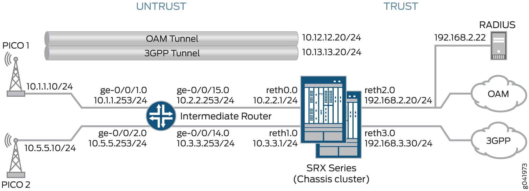
このトポロジーの各ピコセルは、管理用とデータ用の2つのIPsec VPNを開始します。この例では、管理トラフィックはOAMトンネルとラベル付けされたトンネルを使用し、データトラフィックは3GPPトンネルとラベル付けされたトンネルを通過します。各トンネルは、個別の設定可能なネットワーク上のOAMおよび3GPPプロビジョニングサーバーとの接続をサポートしており、個別のルーティングインスタンスとVPNが必要です。この例では、OAMおよび3GPP VPNを確立するためのIKEフェーズ1およびフェーズ2のオプションを提供します。
この例では、SRXシリーズがIKEv2設定ペイロードサーバーとして機能し、RADIUSサーバーからプロビジョニング情報を取得し、その情報をピコセルクライアントに提供します。SRXシリーズは、トンネルネゴシエーション中に、IKEv2設定ペイロード内の承認済み各クライアントのプロビジョニング情報を返します。SRXシリーズはクライアントデバイスとして使用できません。
さらに、SRXシリーズは、IKEv2設定ペイロード情報を使用して、トンネルネゴシエーション中にクライアントと交換するトラフィックセレクターイニシエーター(TSi)とトラフィックセレクターレスポンダー(TSr)値を更新します。設定ペイロードは、[edit security ipsec vpn vpn-name ike]階層レベルのproxy-identityステートメントを使用してSRXシリーズ上で設定されたTSiおよびTSr値を使用します。TSi と TSr の値は、各 VPN のネットワーク トラフィックを定義します。
中間ルーターは、ピコセルトラフィックをSRXシリーズの適切なインターフェイスにルーティングします。
以下のプロセスでは、接続シーケンスについて説明します。
-
ピコセルは、工場出荷時の設定を使用して、SRXシリーズとのIPsecトンネルを開始します。
-
SRXシリーズは、クライアント証明書情報と、SRXシリーズに登録されているCAのルート証明書を使用してクライアントを認証します。認証後、SRXシリーズは、IKE ID情報をクライアント証明書から認証要求としてRADIUSサーバーに渡します。
-
クライアントを認証した後、RADIUSサーバーはクライアントプロビジョニング情報を使用してSRXシリーズに応答します。
-
IPアドレス(TSi値)
-
IPサブネットマスク(オプション、デフォルトは32ビット)
-
DNSアドレス(オプション)
-
-
SRXシリーズは、各クライアント接続のIKEv2設定ペイロード内のプロビジョニング情報を返し、最終的なTSiおよびTSr値をピコセルと交換します。この例では、SRXシリーズは各VPNに対して次のTSiおよびTSr情報を提供します。
VPN接続
SRXから提供されるTSi/TSr値
Pico 1 OAM
TSi:10.12.1.201/32、TSr:192.168.2.0/24
Pico 1 3GPP
TSi:10.13.1.201/32、TSr:192.168.3.0/24、TSr:10.13.0.0/16
Pico 2 OAM
TSi:10.12.1.205/32、TSr:192.168.2.0/24
Pico 2 3GPP
TSi:10.13.1.205/32、TSr:192.168.3.0/24、TSr:10.13.0.0/16
RADIUSサーバーから提供されるプロビジョニング情報にサブネットマスクが含まれている場合、SRXシリーズはIPサブネットを含むクライアント接続の2番目のTSr値を返します。これにより、そのサブネット上のデバイスのピア内通信が可能になります。この例では、3GPP VPN(13.13.0.0/16)に関連するサブネットに対してピア内通信が有効になっています。
IKEv2設定ペイロード機能は、ポイントツーマルチポイントのセキュアトンネル(st0)インターフェイスとポイントツーポイントインターフェイスの両方でサポートされます。ポイントツーマルチポイントインターフェイスの場合、インターフェイスに番号を付ける必要があり、設定ペイロードで指定されたアドレスは、関連するポイントツーマルチポイントインターフェイスのサブネットワーク範囲内にある必要があります。
Junos OSリリース20.1R1以降、SRX5000シリーズおよびikedが動作するvSRX仮想ファイアウォールのポイントツーポイントインターフェイスでIKEv2設定ペイロード機能がサポートされています。
マルチノード高可用性は、セキュアトンネル(st0)用のポイントツーポイントインターフェイスを備えたIKEv2設定ペイロード機能をサポートします。
表7は 、OAMトンネルと3GPPトンネルの両方を確立するための情報を含む、SRXシリーズで設定されたフェーズ1およびフェーズ2のオプションを示しています。
|
オプション |
値 |
|---|---|
| IKEの提案: | |
|
提案名 |
IKE_PROP |
|
認証方法 |
RSA デジタル証明書 |
|
Diffie-Hellman(DH)グループ |
グループ5 |
|
認証アルゴリズム |
SHA-1 |
|
暗号化アルゴリズム |
AES 256 CBC |
| IKEポリシー: | |
|
IKEポリシー名 |
IKE_POL |
|
ローカル証明書 |
Example_SRX |
| IKEゲートウェイ(OAM): | |
|
IKEポリシー |
IKE_POL |
|
リモートIPアドレス |
ダイナミック |
|
IKEユーザータイプ |
グループIKEID |
|
ローカル IKE ID |
ホスト名 srx_series.example.net |
|
リモート IKE ID |
ホスト名 .pico_cell.net |
|
外部インターフェース |
reth0.0 |
|
アクセスプロファイル |
radius_pico |
|
IKEバージョン |
v2のみ |
| IKEゲートウェイ(3GPP): | |
|
IKEポリシー |
IKE_POL |
|
リモートIPアドレス |
動的 |
|
IKEユーザータイプ |
グループIKEID |
|
ローカル IKE ID |
識別名ワイルドカードOU=srx_series |
|
リモート IKE ID |
識別名ワイルドカードOU=pico_cell |
|
外部インターフェース |
reth1 |
|
アクセスプロファイル |
radius_pico |
|
IKEバージョン |
v2のみ |
| IPsecプロポーザル: | |
|
提案名 |
IPSEC_PROP |
|
プロトコル |
ESP |
|
認証アルゴリズム |
HMAC SHA-1 96 |
|
暗号化アルゴリズム |
AES 256 CBC |
| IPsecポリシー: | |
|
ポリシー名 |
IPSEC_POL |
|
完全転送機密保持(PFS)キー |
グループ5 |
|
IPsecの提案 |
IPSEC_PROP |
| IPsec VPN(OAM): | |
|
バインドインターフェイス |
st0.0 |
|
IKEゲートウェイ |
OAM_GW |
|
ローカルプロキシID |
192.168.2.0/24 |
|
リモートプロキシID |
0.0.0.0/0 |
|
IPsecポリシー |
IPSEC_POL |
| IPsec VPN(3GPP): | |
|
バインドインターフェイス |
st0.1 |
|
IKEゲートウェイ |
3GPP_GW |
|
ローカルプロキシID |
192.168.3.0/24 |
|
リモートプロキシID |
0.0.0.0/0 |
|
IPsecポリシー |
IPSEC_POL |
証明書は、ピコセルとSRXシリーズに保存されます。
この例では、すべてのトラフィックを許可するデフォルトのセキュリティポリシーがすべてのデバイスで使用されています。実稼働環境では、より制限の厳しいセキュリティポリシーを設定する必要があります。 「セキュリティポリシーの概要」を参照してください。
設定
SRXシリーズの設定
CLIクイックコンフィグレーション
この例をすばやく設定するには、以下のコマンドをコピーしてテキスト ファイルに貼り付け、改行を削除し、ネットワーク設定に一致させる必要がある詳細情報を変更し、コマンドを [edit] 階層レベルでCLIにコピー アンド ペーストして、設定モードから commit を入力します。
set chassis cluster reth-count 5
set chassis cluster node 0
set chassis cluster node 1
set chassis cluster redundancy-group 0 node 0 priority 250
set chassis cluster redundancy-group 0 node 1 priority 150
set chassis cluster redundancy-group 1 node 0 priority 220
set chassis cluster redundancy-group 1 node 1 priority 149
set chassis cluster redundancy-group 1 interface-monitor ge-3/0/0 weight 255
set chassis cluster redundancy-group 1 interface-monitor ge-8/0/0 weight 255
set chassis cluster redundancy-group 1 interface-monitor ge-3/0/1 weight 255
set chassis cluster redundancy-group 1 interface-monitor ge-8/0/1 weight 255
set chassis cluster redundancy-group 1 interface-monitor ge-3/2/0 weight 255
set chassis cluster redundancy-group 1 interface-monitor ge-8/2/0 weight 255
set chassis cluster redundancy-group 1 interface-monitor ge-3/2/1 weight 255
set chassis cluster redundancy-group 1 interface-monitor ge-8/2/1 weight 255
set interfaces ge-3/0/0 gigether-options redundant-parent reth0
set interfaces ge-3/0/1 gigether-options redundant-parent reth1
set interfaces ge-3/2/0 gigether-options redundant-parent reth2
set interfaces ge-3/2/1 gigether-options redundant-parent reth3
set interfaces ge-8/0/0 gigether-options redundant-parent reth0
set interfaces ge-8/0/1 gigether-options redundant-parent reth1
set interfaces ge-8/2/0 gigether-options redundant-parent reth2
set interfaces ge-8/2/1 gigether-options redundant-parent reth3
set interfaces reth0 redundant-ether-options redundancy-group 1
set interfaces reth0 unit 0 family inet address 10.2.2.1/24
set interfaces reth1 redundant-ether-options redundancy-group 1
set interfaces reth1 unit 0 family inet address 10.3.3.1/24
set interfaces reth2 redundant-ether-options redundancy-group 1
set interfaces reth2 unit 0 family inet address 192.168.2.20/24
set interfaces reth3 redundant-ether-options redundancy-group 1
set interfaces reth3 unit 0 family inet address 192.168.3.20/24
set interfaces st0 unit 0 multipoint
set interfaces st0 unit 0 family inet address 10.12.1.20/24
set interfaces st0 unit 1 multipoint
set interfaces st0 unit 1 family inet address 10.13.1.20/24
set routing-options static route 10.1.0.0/16 next-hop 10.2.2.253
set routing-options static route 10.5.0.0/16 next-hop 10.2.2.253
set security zones security-zone untrust host-inbound-traffic system-services all
set security zones security-zone untrust host-inbound-traffic protocols all
set security zones security-zone untrust interfaces reth0.0
set security zones security-zone untrust interfaces reth1.0
set security zones security-zone oam-trust host-inbound-traffic system-services all
set security zones security-zone oam-trust host-inbound-traffic protocols all
set security zones security-zone oam-trust interfaces reth2.0
set security zones security-zone oam-trust interfaces st0.0
set security zones security-zone 3gpp-trust host-inbound-traffic system-services all
set security zones security-zone 3gpp-trust host-inbound-traffic protocols all
set security zones security-zone 3gpp-trust interfaces reth3.0
set security zones security-zone 3gpp-trust interfaces st0.1
set access profile radius_pico authentication-order radius
set access profile radius_pico radius-server 192.168.2.22 secret "$ABC123"
set access profile radius_pico radius-server 192.168.2.22 routing-instance VR-OAM
set security ike proposal IKE_PROP authentication-method rsa-signatures
set security ike proposal IKE_PROP dh-group group5
set security ike proposal IKE_PROP authentication-algorithm sha1
set security ike proposal IKE_PROP encryption-algorithm aes-256-cbc
set security ike policy IKE_POL proposals IKE_PROP
set security ike policy IKE_POL certificate local-certificate example_SRX
set security ike gateway OAM_GW ike-policy IKE_POL
set security ike gateway OAM_GW dynamic hostname .pico_cell.net
set security ike gateway OAM_GW dynamic ike-user-type group-ike-id
set security ike gateway OAM_GW local-identity hostname srx_series.example.net
set security ike gateway OAM_GW external-interface reth0.0
set security ike gateway OAM_GW aaa access-profile radius_pico
set security ike gateway OAM_GW version v2-only
set security ike gateway 3GPP_GW ike-policy IKE_POL
set security ike gateway 3GPP_GW dynamic distinguished-name wildcard OU=pico_cell
set security ike gateway 3GPP_GW dynamic ike-user-type group-ike-id
set security ike gateway 3GPP_GW local-identity distinguished-name wildcard OU=srx_series
set security ike gateway 3GPP_GW external-interface reth1.0
set security ike gateway 3GPP_GW aaa access-profile radius_pico
set security ike gateway 3GPP_GW version v2-only
set security ipsec proposal IPSEC_PROP protocol esp
set security ipsec proposal IPSEC_PROP authentication-algorithm hmac-sha1-96
set security ipsec proposal IPSEC_PROP encryption-algorithm aes-256-cbc
set security ipsec proposal IPSEC_PROP lifetime-seconds 300
set security ipsec policy IPSEC_POL perfect-forward-secrecy keys group5
set security ipsec policy IPSEC_POL proposals IPSEC_PROP
set security ipsec vpn OAM_VPN bind-interface st0.0
set security ipsec vpn OAM_VPN ike gateway OAM_GW
set security ipsec vpn OAM_VPN ike proxy-identity local 192.168.2.0/24
set security ipsec vpn OAM_VPN ike proxy-identity remote 0.0.0.0/0
set security ipsec vpn OAM_VPN ike ipsec-policy IPSEC_POL
set security ipsec vpn 3GPP_VPN bind-interface st0.1
set security ipsec vpn 3GPP_VPN ike gateway 3GPP_GW
set security ipsec vpn 3GPP_VPN ike proxy-identity local 192.168.3.0/24
set security ipsec vpn 3GPP_VPN ike proxy-identity remote 0.0.0.0/0
set security ipsec vpn 3GPP_VPN ike ipsec-policy IPSEC_POL
set routing-instances VR-OAM instance-type virtual-router
set routing-instances VR-OAM interface reth2.0
set routing-instances VR-OAM interface st0.0
set routing-instances VR-3GPP instance-type virtual-router
set routing-instances VR-3GPP interface reth3.0
set routing-instances VR-3GPP interface st0.1
set security policies default-policy permit-all
ステップバイステップの手順
次の例では、設定階層のさまざまなレベルに移動する必要があります。その方法の詳細については、 設定モードでの CLI エディターの使用を参照してください。
SRXシリーズを設定するには:
-
シャーシ クラスターを設定します。
[edit chassis cluster]
user@host# set reth-count 5
user@host# set node 0
user@host# set node 1
user@host#set redundancy-group 0 node 0 priority 250
user@host#set redundancy-group 0 node 1 priority 150
user@host#set redundancy-group 1 node 0 priority 220
user@host#set redundancy-group 1 node 1 priority 149
user@host# set redundancy-group 1 interface-monitor ge-3/0/0 weight 255
user@host# set redundancy-group 1 interface-monitor ge-8/0/0 weight 255
user@host# set redundancy-group 1 interface-monitor ge-3/0/1 weight 255
user@host# set redundancy-group 1 interface-monitor ge-8/0/1 weight 255
user@host# set redundancy-group 1 interface-monitor ge-3/2/0 weight 255
user@host# set redundancy-group 1 interface-monitor ge-8/2/0 weight 255
user@host# set redundancy-group 1 interface-monitor ge-3/2/1 weight 255
user@host# set redundancy-group 1 interface-monitor ge-8/2/1 weight 255
-
インターフェイスを設定します。
[edit interfaces]
user@host# set ge-3/0/0 gigether-options redundant-parent reth0
user@host# set ge-3/0/1 gigether-options redundant-parent reth1
user@host# set ge-3/2/0 gigether-options redundant-parent reth2
user@host# set ge-3/2/1 gigether-options redundant-parent reth3
user@host# set ge-8/0/0 gigether-options redundant-parent reth0
user@host# set ge-8/0/1 gigether-options redundant-parent reth1
user@host# set ge-8/2/0 gigether-options redundant-parent reth2
user@host# set ge-8/2/1 gigether-options redundant-parent reth3
user@host# set reth0 redundant-ether-options redundancy-group 1
user@host# set reth0 unit 0 family inet address 10.2.2.1/24
user@host# set reth1 redundant-ether-options redundancy-group 1
user@host# set reth1 unit 0 family inet address 10.3.3.1/24
user@host# set reth2 redundant-ether-options redundancy-group 1
user@host# set reth2 unit 0 family inet address 192.168.2.20/24
user@host# set reth3 redundant-ether-options redundancy-group 1
user@host# set reth3 unit 0 family inet address 192.169.3.20/24
user@host# set st0 unit 0 multipoint
user@host# set st0 unit 0 family inet address 10.12.1.20/24
user@host# set st0 unit 1 multipoint
user@host# set st0 unit 1 family inet address 10.13.1.20/24
-
ルーティングオプションを設定します。
[edit routing-options]
user@host# set static route 10.1.0.0/16 next-hop 10.2.2.253
user@host# set static route 10.5.0.0/16 next-hop 10.2.2.253
-
セキュリティゾーンを指定します。
[edit security zones security-zone untrust]
user@host# set host-inbound-traffic protocols all
user@host# set host-inbound-traffic system-services all
user@host# set interfaces reth0.0
user@host# set interfaces reth1.0
[edit security zones security-zone oam-trust]
user@host# set host-inbound-traffic system-services all
user@host# set host-inbound-traffic protocols all
user@host# set interfaces reth2.0
user@host# set interfaces st0.0
[edit security zones security-zone 3gpp-trust]
user@host# set host-inbound-traffic system-services all
user@host# set host-inbound-traffic protocols all
user@host# set interfaces reth3.0
user@host# set interfaces st0.1
-
RADIUSプロファイルを作成します。
[edit access profile radius_pico]
user@host# set authentication-order radius
user@host# set radius-server 192.168.2.22 secret “$ABC123”
user@host# set radius-server 192.168.2.22 routing-instance VR-OAM
-
フェーズ1のオプションを設定します。
[edit security ike proposal IKE_PROP]
user@host# set authentication-method rsa-signatures
user@host# set dh-group group5
user@host# set authentication-algorithm sha1
user@host# set encryption-algorithm aes-256-cbc
[edit security ike policy IKE_POL]
user@host# set proposals IKE_PROP
user@host# set certificate local-certificate example_SRX
[edit security ike gateway OAM_GW]
user@host# set ike-policy IKE_POL
user@host# set dynamic hostname .pico_cell.net
user@host# set dynamic ike-user-type group-ike-id
user@host# set local-identity hostname srx.example.net
user@host# set external-interface reth0.0
user@host# set aaa access-profile radius_pico
user@host# set version v2-only
[edit security ike gateway 3GPP_GW]
user@host# set ike-policy IKE_POL
user@host# set dynamic distinguished-name wildcard OU=pico_cell
user@host# set dynamic ike-user-type group-ike-id
user@host# set local-identity distinguished-name wildcard OU=srx_series
user@host# set external-interface reth1.0
user@host# set aaa access-profile radius_pico
user@host# set version v2-only
-
フェーズ 2 のオプションを指定します。
[edit set security ipsec proposal IPSEC_PROP]
user@host# set protocol esp
user@host# set authentication-algorithm hmac-sha1-96
user@host# set encryption-algorithm aes-256-cbc
user@host# set lifetime-seconds 300
[edit security ipsec policy IPSEC_POL]
user@host# set perfect-forward-secrecy keys group5
user@host# set proposals IPSEC_PROP
[edit security ipsec vpn OAM_VPN]
user@host# set bind-interface st0.0
user@host# set ike gateway OAM_GW
user@host# set ike proxy-identity local 192.168.2.0/24
user@host# set ike proxy-identity remote 0.0.0.0/0
user@host# set ike ipsec-policy IPSEC_POL
[edit security ipsec vpn 3GPP_VPN]
user@host# set bind-interface st0.1
user@host# set ike gateway 3GPP_GW
user@host# set ike proxy-identity local 192.168.3.0/24
user@host# set ike proxy-identity remote 0.0.0.0/0
user@host# set ike ipsec-policy IPSEC_POL
-
ルーティングインスタンスを指定します。
[edit routing-instances VR-OAM]
user@host# set instance-type virtual router
user@host# set interface reth2.0
user@host# set interface st0.0
[edit routing-instances VR-3GPP]
user@host# set instance-type virtual router
user@host# set interface reth3.0
user@host# set interface st0.1
-
サイト間トラフィックを許可するセキュリティポリシーを指定します。
[edit security policies]
user@host# set default-policy permit-all
結果
設定モードから、 show chassis cluster、 show interfaces、 show security zones、 show access profile radius_pico、 show security ike、 show security ipsec、 show routing-instances、および show security policies コマンドを入力して、設定を確認します。出力に意図した設定が表示されない場合は、この例の設定手順を繰り返して修正します。
[edit]
user@host# show chassis cluster
reth-count 5
node 0
node 1
redundancy-group 0{
    node 0 priority 250;
    node 1 priority 150;
    redundancy-group 1 {
    node 0 priority 220;
    node 1 priority 149;
    interface-monitor {
        ge-3/0/0 weight 255;
        ge-8/0/0 weight 255;
        ge-3/0/1 weight 255;
        ge-8/0/1 weight 255;
        ge-3/2/0 weight 255;
        ge-8/2/0 weight 255;
        ge-3/2/1 weight 255;
        ge-8/2/1 weight 255;
    }
}
[edit]
user@host# show interfaces
ge-3/0/0 {
    gigether-options {
        redundant-parent reth0;
    }
}
ge-3/0/1 {
    gigether-options {
        redundant-parent reth1;
    }
}
ge-3/2/0 {
    gigether-options {
        redundant-parent reth2;
    }
}
ge-3/2/1 {
    gigether-options {
        redundant-parent reth3;
    }
}
ge-8/0/0 {
    gigether-options {
        redundant-parent reth0;
    }
}
ge-8/0/1 {
    gigether-options {
        redundant-parent reth1;
    }
}
ge-8/2/0 {
    gigether-options {
        redundant-parent reth2;
    }
}
ge-8/2/1 {
    gigether-options {
        redundant-parent reth3;
    }
}
reth0 {
    redundant-ether-options {
        redundancy-group 1;
    }
    unit 0 {
        family inet {
            address 10.2.2.1/24;
        }
    }
}
reth1 {
    redundant-ether-options {
        redundancy-group 1;
    }
    unit 0 {
        family inet {
            address 10.3.3.1/24;
        }
    }
}
reth2 {
    redundant-ether-options {
        redundancy-group 1;
    }
    unit 0 {
        family inet {
            address 192.168.2.20/24;
        }
    }
}
reth3 {
    redundant-ether-options {
        redundancy-group 1;
    }
    unit 0 {
        family inet {
            address 192.168.3.20/24;
        }
    }
}
st0 {
    unit 0{
        multipoint;
        family inet {
            address 12.12.1.20/24;
        }
    }
    unit 1{
        multipoint;
        family inet {
            address 13.13.1.20/24;
        }
    }
}
[edit]
user@host# show routing-options
static {
    route 10.1.0.0/16 next-hop 10.2.2.253;
    route 10.5.0.0/16 next-hop 10.2.2.253;
}
[edit]
user@host# show security zones
security-zone untrust {
    host-inbound-traffic {
        system-services {
            all;
        }
        protocols {
            all;
        }
    }
    interfaces {
        reth1.0;
        reth0.0;
    }
}
security-zone oam-trust {
    host-inbound-traffic {
        system-services {
            all;
        }
        protocols {
            all;
        }
    }
    interfaces {
        reth2.0;
        st0.0;
    }
}
security-zone 3gpp-trust {
    host-inbound-traffic {
        system-services {
            all;
        }
        protocols {
            all;
        }
    }
    interfaces {
        reth3.0;
        st0.1;
    }
}
[edit]
user@host# show access profile radius_pico
authentication-order radius;
radius-server {
    192.168.2.22 {
        secret "$ABC123";
        routing-instance VR-OAM;
    }
}
[edit]
user@host# show security ike
proposal IKE_PROP {
    authentication-method rsa-signatures;
    dh-group group5;
    authentication-algorithm sha1;
    encryption-algorithm aes-256-cbc;
}
policy IKE_POL {
    proposals IKE_PROP;
    certificate {
        local-certificate example_SRX;
    }
}
gateway OAM_GW {
    ike-policy IKE_POL;
    dynamic {
        hostname .pico_cell.net;
        ike-user-type group-ike-id;
    }
    local-identity hostname srx_series.example.net;
    external-interface reth0.0;
    aaa access-profile radius_pico;
    version v2-only;
}
gateway 3GPP_GW {
    ike-policy IKE_POL;
    dynamic {
        distinguished-name {
            wildcard OU=pico_cell;
        }
        ike-user-type group-ike-id;
    }
    local-identity distinguished-name;
    external-interface reth1.0;
    aaa access-profile radius_pico;
    version v2-only;
}
[edit]
user@host# show security ipsec
proposal IPSEC_PROP {
    protocol esp;
    authentication-algorithm hmac-sha1-96;
    encryption-algorithm aes-256-cbc;
    lifetime-seconds 300;
}
policy IPSEC_POL {
    perfect-forward-secrecy {
        keys group5;
    }
    proposals IPSEC_PROP;
}
vpn OAM_VPN {
    bind-interface st0.0;
    ike {
        gateway OAM_GW;
        proxy-identity {
            local 192.168.2.0/24;
            remote 0.0.0.0/0;
        }
        ipsec-policy IPSEC_POL;
    }
}
vpn 3GPP_VPN {
    bind-interface st0.1;
    ike {
        gateway 3GPP_GW;
        proxy-identity {
            local 192.168.3.0/24;
            remote 0.0.0.0/0;
        }
        ipsec-policy IPSEC_POL;
    }
}
[edit]
user@host# show routing-instances
VR-OAM {
    instance-type virtual-router;
    interface reth2.0;
    interface st0.0;
}
VR-3GPP {
    instance-type virtual-router;
    interface reth3.0;
    interface st0.1;
}
[edit]
user@host# show security policies
default-policy {
    permit-all;
}
デバイスの設定が完了したら、設定モードから commit を入力します。
中間ルーターの設定
CLIクイックコンフィグレーション
この例をすばやく設定するには、以下のコマンドをコピーしてテキスト ファイルに貼り付け、改行を削除し、ネットワーク設定に一致させる必要がある詳細情報を変更し、コマンドを [edit] 階層レベルでCLIにコピー アンド ペーストして、設定モードから commit を入力します。
set interfaces ge-0/0/1 unit 0 family inet address 10.1.1.253/24
set interfaces ge-0/0/2 unit 0 family inet address 10.5.5.253/24
set interfaces ge-0/0/14 unit 0 family inet address 10.3.3.253/24
set interfaces ge-0/0/15 unit 0 family inet address 10.2.2.253/24
set routing-options static route 192.168.3.0/24 next-hop 10.2.2.1
set security zones security-zone trust host-inbound-traffic system-services all
set security zones security-zone trust host-inbound-traffic protocols all
set security zones security-zone trust interfaces ge-0/0/14.0
set security zones security-zone trust interfaces ge-0/0/15.0
set security zones security-zone untrust host-inbound-traffic system-services all
set security zones security-zone untrust host-inbound-traffic protocols all
set security zones security-zone untrust interfaces ge-0/0/1.0
set security zones security-zone untrust interfaces ge-0/0/2.0
set security policies default-policy permit-all
ステップバイステップの手順
次の例では、設定階層のさまざまなレベルに移動する必要があります。その方法の詳細については、 設定モードでの CLI エディターの使用を参照してください。
中間ルーターを設定するには:
-
インターフェイスを設定します。
[edit interfaces]
user@host# set ge-0/0/1 unit 0 family inet address 10.1.1.253/24
user@host# set ge-0/0/2 unit 0 family inet address 10.5.5.253/24
user@host# set ge-0/0/14 unit 0 family inet address 10.3.3.253/24
user@host# set ge-0/0/15 unit 0 family inet address 10.2.2.253/24
-
ルーティングオプションを設定します。
[edit routing-options]
user@host# set static route 192.168.3.0/24  next-hop 10.2.2.1
-
セキュリティゾーンを指定します。
[edit security zones security-zone trust]
user@host# set host-inbound-traffic protocols all
user@host# set host-inbound-traffic system-services all
user@host# set interfaces ge-0/0/14.0
user@host# set interfaces ge-0/0/15.0
[edit security zones security-zone untrust]
user@host# set host-inbound-traffic system-services all
user@host# set host-inbound-traffic protocols all
user@host# set interfaces ge-0/0/1.0
user@host# set interfaces ge-0/0/2.0
-
セキュリティポリシーを指定します。
[edit security policies]
user@host# set default-policy permit-all
結果
設定モードから、 show interfaces、 show routing-options、 show security zones、および show security policies コマンドを入力して設定を確認します。出力に意図した設定が表示されない場合は、この例の設定手順を繰り返して修正します。
[edit]
user@host# show interfaces
ge-0/0/1 {
    unit 0 {
        family inet {
            address 10.1.1.253/24;
        }
    }
}
ge-0/0/2 {
    unit 0 {
        family inet {
            address 10.5.5.253/24;
        }
    }
}
ge-0/0/14 {
    unit 0 {
        family inet {
            address 10.3.3.253/24;
        }
    }
}
ge-0/0/15 {
    unit 0 {
        family inet {
            address 10.2.2.253/24;
        }
    }
}
[edit]
user@host# show routing-options
static {
    route 192.168.3.0/24 next-hop 10.2.2.1;
}
[edit]
user@host# show security zones
security-zone trust {
    host-inbound-traffic {
        system-services {
            all;
        }
        protocols {
            all;
        }
    }
    interfaces {
        ge-0/0/14.0;
        ge-0/0/15.0;
    }
}
security-zone untrust {
    host-inbound-traffic {
        system-services {
            all;
        }
        protocols {
            all;
        }
    }
    interfaces {
        ge-0/0/1.0;
        ge-0/0/2.0;
    }
}
}
[edit]
user@host# show security policies
default-policy {
    permit-all;
}
デバイスの設定が完了したら、設定モードから commit を入力します。
Picoセルの設定(設定例)
ステップバイステップの手順
この例のピコセル情報は、参照用に提供されています。ピコセル設定の詳細な情報は、このドキュメントの範囲外です。ピコセルの工場出荷時設定には、以下の情報を含める必要があります。
-
ローカル証明書(X.509v3)とIKE ID情報
-
トラフィックセレクター(TSi、TSr)値が任意/任意(0.0.0.0/0)に設定されている
-
SRXシリーズのIKE ID情報とパブリックIPアドレス
-
SRXシリーズの設定に一致するフェーズ1およびフェーズ2のプロポーザル
この例のピコセルは、IPsecベースのVPN接続にstrongSwansオープンソースソフトウェアを使用しています。この情報は、IKEv2設定ペイロード機能を使用したピコセルプロビジョニングのために、SRXシリーズで使用されます。多くのデバイスが導入されているネットワークでは、証明書(leftcert)とID(leftID)情報を除き、ピコセルの設定を同一にすることができます。次の設定例は、工場出荷時の設定を示しています。
-
Pico 1の設定を確認します。
Pico 1:設定例
conn %default ikelifetime=8h keylife=1h rekeymargin=1m keyingtries=1 keyexchange=ikev2 authby=pubkey mobike=no conn oam left=%any leftsourceip=%config leftcert=/usr/local/etc/ipsec.d/certs/<cert_name> leftid=pico1.pico_cell.net leftfirewall=yes reauth=yes right=10.2.2.1/24 rightid=srx_series.example.net rightsubnet=0.0.0.0/0 #peer net for proxy id ike=aes256-sha-modp1536! esp=aes256-sha-modp1536! auto=add conn 3gpp left=%any leftsourceip=%config leftcert=/usr/local/etc/ipsec.d/certs/<cert_name> leftid=”C=US, ST=CA, L=Sunnyvale, O=org, OU=pico_cell, CN=pico1” leftfirewall=yes reauth=yes right=10.3.3.1/24 rightid=”OU=srx_series” rightsubnet=0.0.0.0/0 #peer net for proxy id ike=aes256-sha-modp1536! esp=aes256-sha-modp1536! auto=add -
Pico 2の設定を確認します。
Pico 2 サンプル設定
conn %default
        ikelifetime=8h
        keylife=1h
        rekeymargin=1m
        keyingtries=1
        keyexchange=ikev2
        authby=pubkey
        mobike=no

conn oam
        left=%any
        leftsourceip=%config
        leftcert=/usr/local/etc/ipsec.d/certs/<cert_name>
        leftid=pico2.pico_cell.net
        leftfirewall=yes
        #reauth=no
        right=10.2.2.1/24
        rightid=srx_series.example.net
        rightsubnet=0.0.0.0/0 #peer net for proxy id
        ike=aes256-sha-modp1536!
        esp=aes256-sha-modp1536!
        auto=add

conn 3gpp
        left=%any
        leftsourceip=%config
        leftcert=/usr/local/etc/ipsec.d/certs/<cert_name>
        leftid=”C=US, ST=CA, L=Sunnyvale, O=org, OU=pico_cell, CN=pico2”
        leftfirewall=yes
        #reauth=no
        right=10.3.3.1/24
        rightid=”OU=srx_series”
        rightsubnet=0.0.0.0/0 #peer net for proxy id
        ike=aes256-sha-modp1536!
        esp=aes256-sha-modp1536!
        auto=add
RADIUSサーバーの設定(FreeRADIUSを使用した設定例)
ステップバイステップの手順
この例の RADIUS サーバー情報は、参照用に提供されています。完全なRADIUSサーバー設定情報は、このドキュメントの範囲外です。以下の情報がRADIUSサーバーによってSRXシリーズに返されます。
-
フレーム化されたIPアドレス
-
Framed-IP-Netmask(オプション)
-
Primary-DNSとSecondary-DNS(オプション)
この例では、RADIUSサーバーにはOAM接続と3GPP接続用の個別のプロビジョニング情報があります。User-Nameは、SRXシリーズの認証要求で提供されたクライアント証明書情報から取得されます。
RADIUSサーバーがDHCPサーバーからクライアントプロビジョニング情報を取得する場合、RADIUSサーバーがDHCPサーバーにリレーするクライアントID情報は、SRXシリーズファイアウォールがRADIUSサーバーにリレーするクライアントIKE ID情報と一致する必要があります。これにより、さまざまなプロトコル間でクライアントIDの連続性が確保されます。
SRXシリーズファイアウォールとRADIUSサーバー間の通信チャネルは、RADIUS共有シークレットによって保護されています。
-
Pico 1 OAM VPNのRADIUS設定を確認します。RADIUSサーバーには、以下の情報があります。
Junos OSリリース12.3X48および15.1X49-D160、17.3R3、17.4R2、18.1R3、18.2R2、18.3R1、18.1R3-S2より前のJunos OSリリースにおけるRADIUS設定例:
FreeRADIUS の設定例:
DEFAULT User-Name =~ "device@example.net", Cleartext-Password := "juniper"
        Service-Type = Framed-User,
        Framed-IP-Address = 10.12.1.201,
        Framed-IP-Netmask = 255.255.255.255,
        Primary-Dns = 192.168.2.104,
        Secondary-Dns = 192.168.2.106,
Junos OSリリース15.X49-D161、15.1X49-D170、17.3R3、17.4R2、18.1R3、18.2R2、18.3R1、18.1R3-S2以降のRADIUS設定例:
FreeRADIUS の設定例:
DEFAULT User-Name =~ "device@example.net", Auth-Type := "Accept"
        Service-Type = Framed-User,
        Framed-IP-Address = 10.12.1.201,
        Framed-IP-Netmask = 255.255.255.255,
        Primary-Dns = 192.168.2.104,
        Secondary-Dns = 192.168.2.106,
この場合、RADIUSサーバーは、イントラピアトラフィックをブロックするデフォルトのサブネットマスク(255.255.255.255)を提供します。
-
Pico 1 3GPP VPNのRADIUS設定を確認します。RADIUSサーバーには、以下の情報があります。
Junos OSリリース12.3X48および15.1X49-D160、17.3R3、17.4R2、18.1R3、18.2R2、18.3R1、18.1R3-S2より前のJunos OSリリースにおけるRADIUS設定例:
FreeRADIUS の設定例:
DEFAULT User-Name =~ "device@example.net", Cleartext-Password := "juniper"
       Service-Type = Framed-User,
        Framed-IP-Address = 10.13.1.201.10,
        Framed-IP-Netmask = 255.255.0.0,
        Primary-Dns = 192.168.2.104,
        Secondary-Dns = 192.168.2.106,
Junos OSリリース15.X49-D161、15.1X49-D170、17.3R3、17.4R2、18.1R3、18.2R2、18.3R1、18.1R3-S2以降のRADIUS設定例:
FreeRADIUS の設定例:
DEFAULT User-Name =~ "device@example.net", Auth-Type := "Accept"
       Service-Type = Framed-User,
        Framed-IP-Address = 10.13.1.201.10,
        Framed-IP-Netmask = 255.255.0.0,
        Primary-Dns = 192.168.2.104,
        Secondary-Dns = 192.168.2.106,
この場合、RADIUS サーバーはサブネット マスク値(255.255.0.0)を提供し、イントラピア トラフィックを有効にします。
Junos OS リリース 20.1R1 以降、IKE ゲートウェイ構成の IKEv2 構成ペイロード要求に共通のパスワードを構成できるようになりました。1文字から128文字の範囲の共通パスワードで、管理者は共通パスワードを定義できます。このパスワードは、SRXシリーズファイアウォールがIKEv2設定ペイロードを使用してリモートIPsecピアに代わってIPアドレスを要求する場合に、SRXシリーズファイアウォールとRADIUSサーバーの間で使用されます。RADIUSサーバーは、設定ペイロード要求に対してSRXシリーズファイアウォールにIP情報を提供する前に、認証情報を検証します。共通パスワードは
config-payload-password configured-password構成ステートメントを使用して階層レベルで構成できます[edit security ike gateway gateway-name aaa access-profile access-profile-name]。さらに、この例では、ユーザー名(IKE ID)情報用の証明書の異なる部分を使用して、同じクライアント証明書から 2 つのトンネルを作成します。
検証
設定が正常に機能していることを確認します。
SRXシリーズのIKEフェーズ1ステータスの確認
目的
IKEフェーズ1ステータスを確認します。
アクション
ノード0の動作モードから、 show security ike security-associations コマンドを入力します。コマンドからインデックス番号を取得した後、 show security ike security-associations detail コマンドを使用します。
user@host# show security ike security-associations
node0:
--------------------------------------------------------------------------
Index      State  Initiator cookie  Responder cookie  Mode  Remote Address
553329718  UP     99919a471d1a5278  3be7c5a49172e6c2  IKEv2 10.1.1.1
1643848758 UP     9e31d4323195a195  4d142438106d4273  IKEv2 10.1.1.1
user@host# show security ike security-associations index 553329718 detail
node0:
--------------------------------------------------------------------------
IKE peer 10.1.1.1, Index 553329718, Gateway Name: OAM_GW
  Location: FPC 2, PIC 0, KMD-Instance 1
  Role: Responder, State: UP
  Initiator cookie: 99919a471d1a5278, Responder cookie: 3be7c5a49172e6c2
  Exchange type: IKEv2, Authentication method: RSA-signatures
  Local: 10.2.2.1:500, Remote: 10.1.1.1:500
  Lifetime: Expires in 28738 seconds
  Peer ike-id: C=US, ST=CA, L=Sunnyvale, O=org, OU=pico_cell, CN=pico1
  aaa assigned IP: 10.12.1.201
  Algorithms:
   Authentication        : hmac-sha1-96
   Encryption            : aes256-cbc
   Pseudo random function: hmac-sha1
   Diffie-Hellman group  : DH-group-5
  Traffic statistics:
   Input  bytes  :                 2104
   Output bytes  :                  425
  Input  packets:                    2
   Output packets:                    1
  IPSec security associations: 0 created, 0 deleted
  Phase 2 negotiations in progress: 1
意味
show security ike security-associationsコマンドは、ピコセルデバイスを持つすべてのアクティブなIKEフェーズ1のSAを一覧表示します。SAが表示されない場合は、フェーズ1の確立に問題があったことを示しています。設定でIKEポリシーパラメータと外部インターフェイスの設定を確認してください。この例では、OAM VPN の IKE フェーズ 1 SA のみを示しています。ただし、3GPP VPNのIKEフェーズ1パラメータを示す別のIKEフェーズ1SAが表示されます。
SAが表示される場合は、以下の情報を確認します。
-
インデックス—この値は各IKE SAに固有です。
show security ike security-associations index detailコマンドを使用すると、SAに関する詳細情報を得ることができます。 -
リモートアドレス—ローカルIPアドレスが正しいことと、ポート500がピアツーピア通信に使用されていることを確認します。
-
ロールレスポンダーの状態:
-
Up:フェーズ1SAが確立されました。
-
Down - フェーズ 1 SA の確立に問題がありました。
-
-
ピア(リモート)IKE ID—証明書情報が正しいことを確認します。
-
ローカルIDとリモートID—これらのアドレスが正しいことを確認してください。
-
モード—正しいモードが使用されていることを確認します。
設定で次の項目が正しいことを確認します。
-
外部インターフェイス(インターフェイスはIKEパケットを送信するインターフェイスである必要があります)
-
IKEポリシーパラメータ
-
フェーズ1のプロポーザルパラメーター(ピア間で一致する必要があります)
show security ike security-associationsコマンドは、セキュリティアソシエーションに関する以下の追加情報を一覧表示します。
-
使用される認証および暗号化アルゴリズム
-
フェーズ1のライフタイム
-
トラフィック統計情報(トラフィックが双方向に正しく流れていることを検証するために使用できます)
-
ロール情報
トラブルシューティングは、レスポンダ ロールを使用してピア上で実行するのが最適です。
-
開始側と応答側の情報
-
作成されたIPsec SAの数
-
進行中のフェーズ2ネゴシエーションの数
SRXシリーズのIPsecセキュリティアソシエーションの確認
目的
IPsecステータスを確認します。
アクション
ノード0の動作モードから、 show security ipsec security-associations コマンドを入力します。コマンドからインデックス番号を取得した後、 show security ipsec security-associations detail コマンドを使用します。
user@host# show security ipsec security-associations
node0:
--------------------------------------------------------------------------
  Total active tunnels: 2
  ID         Algorithm             SPI     Life:sec/kb Mon lsys Port Gateway
  <214171651 ESP:aes-cbc-256/sha1 cc2869e2 3529/        -  root 500  10.1.1.1
  >214171651 ESP:aes-cbc-256/sha1 c0a54936 3529/        -  root 500  10.1.1.1
  <205520899 ESP:aes-cbc-256/sha1 84e49026 3521/        -  root 500  10.1.1.1
  >205520899 ESP:aes-cbc-256/sha1 c4ed1849 3521/        -  root 500  10.1.1.1
user@host# show security ipsec security-associations detail
node0:
--------------------------------------------------------------------------
Port: 500, Nego#: 0, Fail#: 0, Def-Del#: 0 Flag: 0x604a29
Last Tunnel Down Reason: SA not initiated
  ID: 214171651 Virtual-system: root, VPN Name: 3GPP_VPN
  Local Gateway: 10.3.3.1, Remote Gateway: 10.1.1.1
  Local Identity: list(any:0,ipv4_subnet(any:0-65535,[0..7]=192.168.3.0/24), ipv4_subnet(any:0-65535,[0..7]=10.13.0.0/16))
  Remote Identity: ipv4(any:0,[0..3]=10.13.1.201)
    DF-bit: clear
    Bind-interface: st0.1

  Port: 500, Nego#: 0, Fail#: 0, Def-Del#: 0 Flag: 0x608a29
  Last Tunnel Down Reason: SA not initiated
    Location: FPC 6, PIC 0, KMD-Instance 2
    Direction: inbound, SPI: cc2869e2, AUX-SPI: 0
                              , VPN Monitoring: -
    Hard lifetime: Expires in 3523 seconds
    Lifesize Remaining:
    Soft lifetime: Expires in 2965 seconds
    Mode: Tunnel(0 0), Type: dynamic, State: installed
    Protocol: ESP, Authentication: hmac-sha1-96, Encryption: aes-cbc (256 bits)
    Anti-replay service: counter-based enabled, Replay window size: 64

    Location: FPC 6, PIC 0, KMD-Instance 2
    Direction: outbound, SPI: c0a54936, AUX-SPI: 0
                              , VPN Monitoring: -
    Hard lifetime: Expires in 3523 seconds
    Lifesize Remaining:
    Soft lifetime: Expires in 2965 seconds
    Mode: Tunnel(0 0), Type: dynamic, State: installed
    Protocol: ESP, Authentication: hmac-sha1-96, Encryption: aes-cbc (256 bits)
    Anti-replay service: counter-based enabled, Replay window size: 64

  ID: 205520899 Virtual-system: root, VPN Name: OAM_VPN
  Local Gateway: 10.2.2.1, Remote Gateway: 10.1.1.1
  Local Identity: ipv4_subnet(any:0-65535,[0..7]=192.168.2.0/24)
  Remote Identity: ipv4(any:0,[0..3]=10.12.1.201)
  Version: IKEv2
    DF-bit: clear
    Bind-interface: st0.0

  Port: 500, Nego#: 0, Fail#: 0, Def-Del#: 0 Flag: 0x608a29
  Last Tunnel Down Reason: SA not initiated
    Location: FPC 2, PIC 0, KMD-Instance 1
    Direction: inbound, SPI: 84e49026, AUX-SPI: 0
                              , VPN Monitoring: -
    Hard lifetime: Expires in 3515 seconds
    Lifesize Remaining:
    Soft lifetime: Expires in 2933 seconds
    Mode: Tunnel(0 0), Type: dynamic, State: installed
    Protocol: ESP, Authentication: hmac-sha1-96, Encryption: aes-cbc (256 bits)
    Anti-replay service: counter-based enabled, Replay window size: 64

    Location: FPC 2, PIC 0, KMD-Instance 1
    Direction: outbound, SPI: c4ed1849, AUX-SPI: 0
                              , VPN Monitoring: -
    Hard lifetime: Expires in 3515 seconds
    Lifesize Remaining:
    Soft lifetime: Expires in 2933 seconds
    Mode: Tunnel(0 0), Type: dynamic, State: installed
    Protocol: ESP, Authentication: hmac-sha1-96, Encryption: aes-cbc (256 bits)
    Anti-replay service: counter-based enabled, Replay window size: 64
意味
この例では、Pico 1のアクティブなIKEフェーズ2のSAを示しています。SAが表示されない場合は、フェーズ2の確立に問題があったことになります。設定でIPsecポリシーパラメーターを確認します。各フェーズ2SA(OAMおよび3GPP)について、インバウンド方向とアウトボード方向の両方で情報が提供されます。 show security ipsec security-associations コマンドからの出力には、以下の情報が表示されます。
-
リモートゲートウェイのIPアドレスは10.1.1.1です。
-
両方向のSPI、ライフタイム(秒)、使用制限(またはKBで示したライフサイズ)が表示されます。3529/という値は、フェーズ2のライフタイムが3529秒で終了すること、ライフサイズが指定されていないことを示し、無制限であることを示しています。フェーズ2のライフタイムはフェーズ1のライフタイムと異なる場合があります。これは、VPNが起動した後はフェーズ2はフェーズ1に依存しないためです。
-
月曜の列にあるハイフンで示されているように、このSAではVPN監視が有効になっていません。VPN監視が有効な場合、Uは監視が稼働していることを示し、Dは監視が停止していることを示します。
-
仮想システム(vsys)はルート システムであり、常に 0 が表示されます。
上記の show security ipsec security-associations index index_id detail コマンドの出力には、以下の情報が表示されます。
-
ローカル ID とリモート ID により、SA のプロキシ ID が構成されます。
プロキシIDの不一致は、フェーズ2の失敗で最もよくある原因の1つです。IPsec SAが表示されない場合は、プロキシID設定を含むフェーズ2のプロポーザルが両方のピアで正しいことを確認します。ルートベースVPNの場合、デフォルトのプロキシIDはローカル = 0.0.0.0/0、リモート = 0.0.0.0/0、サービス = anyです。同じピアIPからの複数のルートベースVPNで問題が発生する可能性があります。この場合、各IPsec SAに固有のプロキシIDを指定する必要があります。一部のサードパーティベンダーでは、プロキシIDを手動で入力して照合する必要があります。
-
使用される認証および暗号化アルゴリズム。
-
フェーズ2のプロポーザルパラメーター(ピア間で一致する必要があります)。
-
OAMおよび3GPPゲートウェイへのセキュアなトンネル(st0.0およびst0.1)バインディング。
信頼できるCAを使用したIKEポリシー
この例では、信頼できる CA サーバーをピアの IKE ポリシーにバインドする方法を示します。
開始する前に、ピアの IKE ポリシーに関連付けるすべての信頼できる CA のリストを用意しておく必要があります。
IKEポリシーは、単一の信頼できるCAプロファイルまたは信頼できるCAグループに関連付けることができます。セキュアな接続を確立するために、IKEゲートウェイは、証明書を検証する間、IKEポリシーを使用して、設定されたCAグループ(caプロファイル)に自身を制限します。信頼できる CA または信頼できる CA グループ以外のソースから発行された証明書は検証されません。IKEポリシーから証明書検証リクエストがある場合、IKEポリシーに関連付けられたCAプロファイルが証明書を検証します。IKEポリシーがどのCAにも関連付けられていない場合、デフォルトでは、設定されたCAプロファイルのいずれかによって証明書が検証されます。
この例では、 root-ca という名前のCAプロファイルが作成され、そのプロファイルに root-ca-identity が関連付けられています。
信頼できるCAグループに追加したいCAプロファイルは最大20個まで設定できます。信頼できるCAグループで20を超えるCAプロファイルを設定した場合、設定をコミットできません。
デバイスに設定されているCAプロファイルと信頼できるCAグループを表示するには、 show security pki コマンドを実行します。
user@host# show security ike
    proposal ike_prop {
    authentication-method rsa-signatures;
    dh-group group2;
    authentication-algorithm sha-256;
    encryption-algorithm aes-256-cbc;
}
policy ike_policy {
    proposals ike_prop;
    certificate {
        local-certificate SPOKE;
        trusted-ca ca-profile root-ca;
    }
}
show security ikeコマンドは、ike_policyという名前のIKEポリシーの下にCAプロファイルグループと、IKEポリシーに関連付けられた証明書を表示します。