
例:BGP における複数パスのアドバタイズ
この例では、BGPルーターはアクティブなパスのみをアドバタイズするのではなく、複数のパスをアドバタイズするように設定されています。BGPにおける複数パスのアドバタイズについては、RFC 7911、 BGPにおける複数パスのアドバタイズに記載されています。
要件
この例では、以下のハードウェアおよびソフトウェアコンポーネントを使用しています。
8 台の BGP 対応デバイス。
BGP対応デバイスのうち5台は、必ずしもルーターである必要はありません。例えば、EXシリーズのイーサネットスイッチなどです。
BGP対応デバイスのうち3台は、複数パスの送信または複数パスの受信(または複数パスの送信と受信の両方)を行うように設定されています。これら 3 つの BGP 対応デバイスは、M Series マルチサービス エッジ ルーター、MXシリーズ 5G ユニバーサルルーティングプラットフォーム、または T Series コア ルーターである必要があります。
3台のルーターは、Junos OSリリース11.4以降を実行している必要があります。
概要
宛先への複数のパスを設定するには、以下のステートメントを使用します。
[edit protocols bgp group group-name family family]
add-path {
    receive;
    send {
        include-backup-path include-backup-path;
        multipath;
        path-count path-count;
        path-selection-mode {
            (all-paths | equal-cost-paths);
        }
        prefix-policy [ policy-names ... ];
    }
}
この例では、ルーター R5、ルーター R6、ルーター R7 が静的ルートを BGP に再分配しています。ルーター R1 とルーター R4 はルート リフレクタです。ルーター R2 とルーター R3 はルートリフレクタ R1 のクライアントです。ルーター R8 は、ルート リフレクタ R4 のクライアントです。
BGPでマルチパスアドバタイズメントが有効な場合、ルートリフレクションはオプションです。
add-path send path-count 6設定では、ルーター R1 はルーター R4 に最大 6 つのパス(宛先ごと)を送信するように構成されています。
add-path receive設定では、ルーターR4はルーターR1から複数のパスを受信するように構成されています。
add-path send path-count 6設定では、ルーター R4 はルーター R8 に最大 6 本のパスを送信するように構成されています。
add-path receive設定では、ルーター R8 はルーター R4 から複数のパスを受信するように構成されています。
add-path send prefix-policy allow_199ポリシー設定(対応するルート フィルターとともに)は、ルーター R4 が 172.16.199.1/32 ルートのみに対して複数のパスを送信することを制限しています。
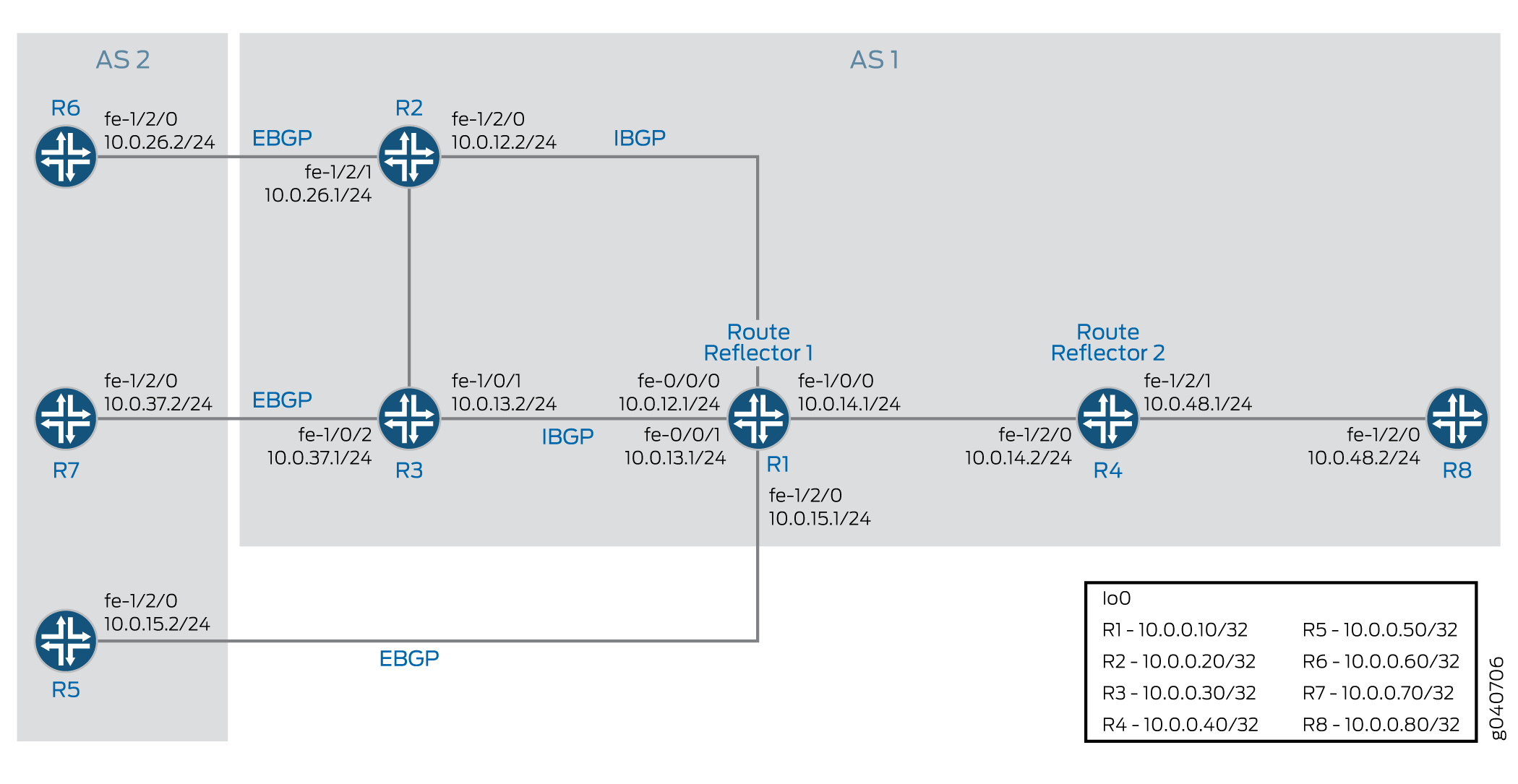
設定
- CLIクイックコンフィグレーション
- ルーターR1の設定
- ルーターR2の設定
- ルーターR3の設定
- ルーターR4の設定
- ルーターR5の設定
- ルーターR6の設定
- ルーターR7の設定
- ルーターR8の設定
- 結果
CLIクイックコンフィグレーション
この例をすばやく設定するには、以下のコマンドをコピーしてテキストファイルに貼り付け、改行を削除して、ネットワーク構成に合わせて必要な詳細を変更してから、コマンドを [edit] 階層レベルのCLIにコピー&ペーストします。
ルーターR1
set interfaces fe-0/0/0 unit 12 family inet address 10.0.12.1/24
set interfaces fe-0/0/1 unit 13 family inet address 10.0.13.1/24
set interfaces fe-1/0/0 unit 14 family inet address 10.0.14.1/24
set interfaces fe-1/2/0 unit 15 family inet address 10.0.15.1/24
set interfaces lo0 unit 10 family inet address 10.0.0.10/32
set protocols bgp group rr type internal
set protocols bgp group rr local-address 10.0.0.10
set protocols bgp group rr cluster 10.0.0.10
set protocols bgp group rr neighbor 10.0.0.20
set protocols bgp group rr neighbor 10.0.0.30
set protocols bgp group e1 type external
set protocols bgp group e1 neighbor 10.0.15.2 local-address 10.0.15.1
set protocols bgp group e1 neighbor 10.0.15.2 peer-as 2
set protocols bgp group rr_rr type internal
set protocols bgp group rr_rr local-address 10.0.0.10
set protocols bgp group rr_rr neighbor 10.0.0.40 family inet unicast add-path send path-count 6
set protocols ospf area 0.0.0.0 interface lo0.10 passive
set protocols ospf area 0.0.0.0 interface fe-0/0/0.12
set protocols ospf area 0.0.0.0 interface fe-0/0/1.13
set protocols ospf area 0.0.0.0 interface fe-1/0/0.14
set protocols ospf area 0.0.0.0 interface fe-1/2/0.15
set routing-options router-id 10.0.0.10
set routing-options autonomous-system 1
ルーターR2
set interfaces fe-1/2/0 unit 21 family inet address 10.0.12.2/24
set interfaces fe-1/2/1 unit 26 family inet address 10.0.26.1/24
set interfaces lo0 unit 20 family inet address 10.0.0.20/32
set protocols bgp group rr type internal
set protocols bgp group rr local-address 10.0.0.20
set protocols bgp group rr neighbor 10.0.0.10 export set_nh_self
set protocols bgp group e1 type external
set protocols bgp group e1 neighbor 10.0.26.2 peer-as 2
set protocols ospf area 0.0.0.0 interface lo0.20 passive
set protocols ospf area 0.0.0.0 interface fe-1/2/0.21
set protocols ospf area 0.0.0.0 interface fe-1/2/1.28
set policy-options policy-statement set_nh_self then next-hop self
set routing-options autonomous-system 1
ルーターR3
set interfaces fe-1/0/1 unit 31 family inet address 10.0.13.2/24
set interfaces fe-1/0/2 unit 37 family inet address 10.0.37.1/24
set interfaces lo0 unit 30 family inet address 10.0.0.30/32
set protocols bgp group rr type internal
set protocols bgp group rr local-address 10.0.0.30
set protocols bgp group rr neighbor 10.0.0.10 export set_nh_self
set protocols bgp group e1 type external
set protocols bgp group e1 neighbor 10.0.37.2 peer-as 2
set protocols ospf area 0.0.0.0 interface lo0.30 passive
set protocols ospf area 0.0.0.0 interface fe-1/0/1.31
set protocols ospf area 0.0.0.0 interface fe-1/0/2.37
set policy-options policy-statement set_nh_self then next-hop self
set routing-options autonomous-system 1
ルーターR4
set interfaces fe-1/2/0 unit 41 family inet address 10.0.14.2/24
set interfaces fe-1/2/1 unit 48 family inet address 10.0.48.1/24
set interfaces lo0 unit 40 family inet address 10.0.0.40/32
set protocols bgp group rr type internal
set protocols bgp group rr local-address 10.0.0.40
set protocols bgp group rr family inet unicast add-path receive
set protocols bgp group rr neighbor 10.0.0.10
set protocols bgp group rr_client type internal
set protocols bgp group rr_client local-address 10.0.0.40
set protocols bgp group rr_client cluster 10.0.0.40
set protocols bgp group rr_client neighbor 10.0.0.80 family inet unicast add-path send path-count 6
set protocols bgp group rr_client neighbor 10.0.0.80 family inet unicast add-path send prefix-policy allow_199
set protocols ospf area 0.0.0.0 interface fe-1/2/0.41
set protocols ospf area 0.0.0.0 interface lo0.40 passive
set protocols ospf area 0.0.0.0 interface fe-1/2/1.48
set policy-options policy-statement allow_199 from route-filter 172.16.199.1/32 exact
set policy-options policy-statement allow_199 term match_199 from prefix-list match_199
set policy-options policy-statement allow_199 then add-path send-count 20
set policy-options policy-statement allow_199 then accept
set routing-options autonomous-system 1
ルーターR5
set interfaces fe-1/2/0 unit 51 family inet address 10.0.15.2/24
set interfaces lo0 unit 50 family inet address 10.0.0.50/32
set protocols bgp group e1 type external
set protocols bgp group e1 neighbor 10.0.15.1 export s2b
set protocols bgp group e1 neighbor 10.0.15.1 peer-as 1
set policy-options policy-statement s2b from protocol static
set policy-options policy-statement s2b from protocol direct
set policy-options policy-statement s2b then as-path-expand 2
set policy-options policy-statement s2b then accept
set routing-options autonomous-system 2
set routing-options static route 172.16.199.1/32 reject
set routing-options static route 172.16.198.1/32 reject
ルーターR6
set interfaces fe-1/2/0 unit 62 family inet address 10.0.26.2/24
set interfaces lo0 unit 60 family inet address 10.0.0.60/32
set protocols bgp group e1 type external
set protocols bgp group e1 neighbor 10.0.26.1 export s2b
set protocols bgp group e1 neighbor 10.0.26.1 peer-as 1
set policy-options policy-statement s2b from protocol static
set policy-options policy-statement s2b from protocol direct
set policy-options policy-statement s2b then accept
set routing-options autonomous-system 2
set routing-options static route 172.16.199.1/32 reject
set routing-options static route 172.16.198.1/32 reject
ルーターR7
set interfaces fe-1/2/0 unit 73 family inet address 10.0.37.2/24
set interfaces lo0 unit 70 family inet address 10.0.0.70/32
set protocols bgp group e1 type external
set protocols bgp group e1 neighbor 10.0.37.1 export s2b
set protocols bgp group e1 neighbor 10.0.37.1 peer-as 1
set policy-options policy-statement s2b from protocol static
set policy-options policy-statement s2b from protocol direct
set policy-options policy-statement s2b then accept
set routing-options autonomous-system 2
set routing-options static route 172.16.199.1/32 reject
ルーターR8
set interfaces fe-1/2/0 unit 84 family inet address 10.0.48.2/24
set interfaces lo0 unit 80 family inet address 10.0.0.80/32
set protocols bgp group rr type internal
set protocols bgp group rr local-address 10.0.0.80
set protocols bgp group rr neighbor 10.0.0.40 family inet unicast add-path receive
set protocols ospf area 0.0.0.0 interface lo0.80 passive
set protocols ospf area 0.0.0.0 interface fe-1/2/0.84
set routing-options autonomous-system 1
ルーターR1の設定
ステップバイステップの手順
次の例では、設定階層のさまざまなレベルに移動する必要があります。CLIのナビゲーションについては、『Junos OS CLIユーザーガイド』の「設定モードでのCLIエディタの使用」を参照してください。
ルーターR1を設定するには:
ルーター R2、ルーター R3、ルーター R4、およびルーター R5 へのインターフェイスを設定し、ループバック(lo0)インターフェイスを設定します。
[edit interfaces]
user@R1# set fe-0/0/0 unit 12 family inet address 10.0.12.1/24
user@R1# set fe-0/0/1 unit 13 family inet address 10.0.13.1/24
user@R1# set fe-1/0/0 unit 14 family inet address 10.0.14.1/24
user@R1# set fe-1/2/0 unit 15 family inet address 10.0.15.1/24
user@R1#set lo0 unit 10 family inet address 10.0.0.10/32
インターフェイスに BGP を設定し、IBGP ルート リフレクションを設定します。
[edit protocols bgp]
user@R1# set group rr type internal
user@R1# set group rr local-address 10.0.0.10
user@R1# set group rr cluster 10.0.0.10
user@R1# set group rr neighbor 10.0.0.20
user@R1# set group rr neighbor 10.0.0.30
user@R1# set group rr_rr type internal
user@R1# set group rr_rr local-address 10.0.0.10
user@R1# set group e1 type external
user@R1# set group e1 neighbor 10.0.15.2 local-address 10.0.15.1
user@R1# set group e1 neighbor 10.0.15.2 peer-as 2
ルーターR1は、隣接するルーターR4に最大6本のパスを送信するように設定します。
パスの宛先は、ルーター R1 が複数のパスを通じて到達できる任意の宛先とすることができます。
[edit protocols bgp]
user@R1# set group rr_rr neighbor 10.0.0.40 family inet unicast add-path send path-count 6
インターフェイスに OSPF を設定します。
[edit protocols ospf]
user@R1# set area 0.0.0.0 interface lo0.10 passive
user@R1# set area 0.0.0.0 interface fe-0/0/0.12
user@R1# set area 0.0.0.0 interface fe-0/0/1.13
user@R1# set area 0.0.0.0 interface fe-1/0/0.14
user@R1# set area 0.0.0.0 interface fe-1/2/0.15
ルーターIDと自律システム番号を設定します。
[edit routing-options]
user@R1# set router-id 10.0.0.10
user@R1# set autonomous-system 1
デバイスの設定が完了したら、設定をコミットします。
user@R1# commit
結果
設定モードから、 show interfaces、 show protocols、 show policy-options、 show routing-options コマンドを入力して設定を確認します。出力に意図した設定が表示されない場合は、この例の手順を繰り返して設定を修正します。
user@R1# show interfaces
fe-0/0/0 {
    unit 12 {
        family inet {
            address 10.0.12.1/24;
        }
    }
}
fe-0/0/1 {
    unit 13 {
        family inet {
            address 10.0.13.1/24;
        }
    }
}
fe-1/0/0 {
    unit 14 {
        family inet {
            address 10.0.14.1/24;
        }
    }
}
fe-1/2/0 {
    unit 15 {
        family inet {
            address 10.0.15.1/24;
        }
    }
}
lo0 {
    unit 10 {
        family inet {
            address 10.0.0.10/32;
        }
    }
}
user@R1# show protocols
bgp {
    group rr {
        type internal;
        local-address 10.0.0.10;
        cluster 10.0.0.10;
        neighbor 10.0.0.20;
        neighbor 10.0.0.30;
    }
    group e1 {
        type external;
        neighbor 10.0.15.2 {
            local-address 10.0.15.1;
            peer-as 2;
        }
    }
    group rr_rr {
        type internal;
        local-address 10.0.0.10;
        neighbor 10.0.0.40 {
            family inet {
                unicast {
                    add-path {
                        send {
                            path-count 6;
                        }
                    }
                }
            }
        }
    }
}
ospf {
    area 0.0.0.0 {
        interface lo0.10 {
            passive;
        }
        interface fe-0/0/0.12;
        interface fe-0/0/1.13;
        interface fe-1/0/0.14;
        interface fe-1/2/0.15;
    }
}
user@R1# show routing-options
router-id 10.0.0.10;
 autonomous-system 1;
ルーターR2の設定
ステップバイステップの手順
ルーターR2を設定するには:
ループバック(lo0)インタフェースとルーター R6、ルーター R1 へのインタフェースを設定します。
[edit interfaces]
user@R2# set fe-1/2/0 unit 21 family inet address 10.0.12.2/24
user@R2# set fe-1/2/1 unit 26 family inet address 10.0.26.1/24
user@R2# set lo0 unit 20 family inet address 10.0.0.20/32
ルーター R2 のインターフェイスに BGP と OSPF を設定します。
[edit protocols]
user@R2# set bgp group rr type internal
user@R2# set bgp group rr local-address 10.0.0.20
user@R2# set bgp group e1 type external
user@R2# set bgp group e1 neighbor 10.0.26.2 peer-as 2
user@R2# set ospf area 0.0.0.0 interface lo0.20 passive
user@R2# set ospf area 0.0.0.0 interface fe-1/2/0.21
user@R2# set ospf area 0.0.0.0 interface fe-1/2/1.28
ルーターR2からルーターR1へ送信されるルートは、ルーターR1が10.0.26.0/24ネットワーク上のルーターR6のアドレスへのルートを持っていないため、ルーターR2をネクストホップとしてアドバタイズしてください。
[edit]
user@R2# set policy-options policy-statement set_nh_self then next-hop self
user@R2# set protocols bgp group rr neighbor 10.0.0.10 export set_nh_self
自律システム番号を設定します。
[edit]
user@R2# set routing-options autonomous-system 1
デバイスの設定が完了したら、設定をコミットします。
user@R2# commit
結果
設定モードから、 show interfaces、 show protocols、 show policy-options、 show routing-options コマンドを入力して設定を確認します。出力に意図した設定が表示されない場合は、この例の手順を繰り返して設定を修正します。
user@R2# show interfaces
fe-1/2/0 {
    unit 21 {
        family inet {
            address 10.0.12.2/24;
        }
    }
}
fe-1/2/1 {
    unit 26 {
        family inet {
            address 10.0.26.1/24;
        }
    }
}
lo0 {
    unit 20 {
        family inet {
            address 10.0.0.20/32;
        }
    }
}
user@R2# show protocols
bgp {
    group rr {
        type internal;
        local-address 10.0.0.20;
        neighbor 10.0.0.10 {
            export set_nh_self;
        }
    }
    group e1 {
        type external;
        neighbor 10.0.26.2 {
            peer-as 2;
        }
    }
}
ospf {
    area 0.0.0.0 {
        interface lo0.20 {
            passive;
        }
        interface fe-1/2/0.21;
        interface fe-1/2/1.28;
    }
}
user@R2# show policy-options
policy-statement set_nh_self {
    then {
        next-hop self;
    }
}
user@R2# show routing-options
 autonomous-system 1;
ルーターR3の設定
ステップバイステップの手順
ルーターR3を設定するには:
ループバック(lo0)インタフェースと、ルーターR7、ルーターR1へのインタフェースを設定します。
[edit interfaces]
user@R3# set fe-1/0/1 unit 31 family inet address 10.0.13.2/24
user@R3# set fe-1/0/2 unit 37 family inet address 10.0.37.1/24
user@R3# set lo0 unit 30 family inet address 10.0.0.30/32
ルーター R3 のインターフェイスに BGP と OSPF を設定します。
[edit protocols]
user@R3# set bgp group rr type internal
user@R3# set bgp group rr local-address 10.0.0.30
user@R3# set bgp group e1 type external
user@R3# set bgp group e1 neighbor 10.0.37.2 peer-as 2
user@R3# set ospf area 0.0.0.0 interface lo0.30 passive
user@R3# set ospf area 0.0.0.0 interface fe-1/0/1.31
user@R3# set ospf area 0.0.0.0 interface fe-1/0/2.37
ルーターR3からルーターR1へ送信されるルートは、ルーターR1が10.0.37.0/24ネットワーク上のルーターR7のアドレスへのルートを持っていないため、ルーターR3をネクストホップとしてアドバタイズしてください。
[edit]
user@R3# set policy-options policy-statement set_nh_self then next-hop self
user@R3# set protocols bgp group rr neighbor 10.0.0.10 export set_nh_self
自律システム番号を設定します。
[edit]
user@R3# set routing-options autonomous-system 1
デバイスの設定が完了したら、設定をコミットします。
user@R3# commit
結果
設定モードから、 show interfaces、 show protocols、 show policy-options、および show routing-options コマンドを入力して設定を確認します。出力に意図した設定が表示されない場合は、この例の手順を繰り返して設定を修正します。
user@R3# show interfaces
fe-1/0/1 {
    unit 31 {
        family inet {
            address 10.0.13.2/24;
        }
    }
}
fe-1/0/2 {
    unit 37 {
        family inet {
            address 10.0.37.1/24;
        }
    }
}
lo0 {
    unit 30 {
        family inet {
            address 10.0.0.30/32;
        }
    }
}
user@R3# show protocols
bgp {
    group rr {
        type internal;
        local-address 10.0.0.30;
        neighbor 10.0.0.10 {
            export set_nh_self;
        }
    }
    group e1 {
        type external;
        neighbor 10.0.37.2 {
            peer-as 2;
        }
    }
}
ospf {
    area 0.0.0.0 {
        interface lo0.30 {
            passive;
        }
        interface fe-1/0/1.31;
        interface fe-1/0/2.37;
    }
}
user@R3# show policy-options
policy-statement set_nh_self {
    then {
        next-hop self;
    }
}
user@R3# show routing-options
 autonomous-system 1;
ルーターR4の設定
ステップバイステップの手順
ルーターR4を設定するには:
ルーター R1 とルーター R8 のインターフェイスを設定し、ループバック(lo0)インターフェイスを設定します。
[edit interfaces]
user@R4# set fe-1/2/0 unit 41 family inet address 10.0.14.2/24
user@R4# set fe-1/2/1 unit 48 family inet address 10.0.48.1/24
user@R4# set lo0 unit 40 family inet address 10.0.0.40/32
インターフェイスに BGP を設定し、IBGP ルート リフレクションを設定します。
[edit protocols bgp]
user@R4# set group rr type internal
user@R4# set group rr local-address 10.0.0.40
user@R4# set group rr neighbor 10.0.0.10
user@R4# set group rr_client type internal
user@R4# set group rr_client local-address 10.0.0.40
user@R4# set group rr_client cluster 10.0.0.40
ルーターR4は、隣接するルーターR8に最大6本のパスを送信するように設定します。
パスの宛先は、ルーターR4が複数のパスを通じて到達できる任意の宛先とすることができます。
[edit protocols bgp]
user@R4# set group rr_client neighbor 10.0.0.80 family inet unicast add-path send path-count 6
ルーターR4は、隣接するルーターR1から複数のパスを受信するように設定します。
パスの宛先は、ルーター R1 が複数のパスを通じて到達できる任意の宛先とすることができます。
[edit protocols bgp group rr family inet unicast]
user@R4# set add-path receive
インターフェイスに OSPF を設定します。
[edit protocols ospf area 0.0.0.0]
user@R4# set interface fe-1/2/0.41
user@R4# set interface lo0.40 passive
user@R4# set interface fe-1/2/1.48
ルーターR4がルーターR8に対して172.16.199.1/32のルートを複数回送信できるようにポリシーを設定します。
ルーターR4は、172.16.198.1/32ルートと172.16.199.1/32ルートで複数のパスを受信します。ただし、このポリシーのため、ルーターR4は172.16.199.1/32ルートに対してのみ複数のパスを送信します。
[edit protocols bgp group rr_client neighbor 10.0.0.80 family inet unicast]
user@R4# set add-path send prefix-policy allow_199
[edit policy-options policy-statement allow_199]
user@R4# set from route-filter 172.16.199.1/32 exact
user@R4# set then accept
ルーターR4は、アドパスアドバタイズされたプレフィックスのサブセットに対して、最大20 BGP
add-pathルートを送信するように設定することもできます。[edit policy-options policy-statement allow_199] user@R4# set term match_199 from prefix-list match_199 user@R4# set then add-path send-count 20
自律システム番号を設定します。
[edit routing-options]
user@R4# set autonomous-system 1
デバイスの設定が完了したら、設定をコミットします。
user@R4# commit
結果
設定モードから、 show interfaces、 show protocols、 show policy-options、 show routing-options コマンドを入力して設定を確認します。出力に意図した設定が表示されない場合は、この例の手順を繰り返して設定を修正します。
user@R4# show interfaces
fe-1/2/0 {
    unit 41 {
        family inet {
            address 10.0.14.2/24;
        }
    }
}
fe-1/2/1 {
    unit 48 {
        family inet {
            address 10.0.48.1/24;
        }
    }
}
lo0 {
    unit 40 {
        family inet {
            address 10.0.0.40/32;
        }
    }
}
user@R4# show protocols
bgp {
    group rr {
        type internal;
        local-address 10.0.0.40;
        family inet {
            unicast {
                add-path {
                    receive;
                }
            }
        }
        neighbor 10.0.0.10;
    }
    group rr_client {
        type internal;
        local-address 10.0.0.40;
        cluster 10.0.0.40;
        neighbor 10.0.0.80 {
            family inet {
                unicast {
                    add-path {
                        send {
                            path-count 6;
                            prefix-policy allow_199;
                        }
                    }
                }
            }
        }
    }
}
ospf {
    area 0.0.0.0 {
        interface lo0.40 {
            passive;
        }
        interface fe-1/2/0.41;
        interface fe-1/2/1.48;
    }
}
user@R4# show policy-options
policy-statement allow_199 {
    from {
        route-filter 172.16.199.1/32 exact;
    }
    from term match_199 {
        prefix-list match_199;
    }
        then add-path send-count 20;
    then accept;
}
user@R4# show routing-options
 autonomous-system 1;
ルーターR5の設定
ステップバイステップの手順
ルーターR5を設定するには:
ループバック(lo0)インタフェースとルーターR1へのインタフェースを設定します。
[edit interfaces]
user@R5# set fe-1/2/0 unit 51 family inet address 10.0.15.2/24
user@R5# set lo0 unit 50 family inet address 10.0.0.50/32
ルーターR5のインタフェースにBGPを設定します。
[edit protocols bgp group e1]
user@R5# set type external
user@R5# set neighbor 10.0.15.1 peer-as 1
BGPに再配布するためのスタティックルートを作成します。
[edit routing-options]
user@R5# set static route 172.16.199.1/32 reject
user@R5# set static route 172.16.198.1/32 reject
スタティックルートとダイレクトルートをBGPに再分配します。
[edit protocols bgp group e1 neighbor 10.0.15.1]
user@R5# set export s2b
[edit policy-options policy-statement s2b]
user@R5# set from protocol static
user@R5# set from protocol direct
user@R5# set then as-path-expand 2
user@R5# set then accept
自律システム番号を設定します。
[edit routing-options]
user@R5# set autonomous-system 2
デバイスの設定が完了したら、設定をコミットします。
user@R5# commit
結果
設定モードから、 show interfaces、 show protocols、 show policy-options、および show routing-options コマンドを入力して設定を確認します。出力に意図した設定が表示されない場合は、この例の手順を繰り返して設定を修正します。
user@R5# show interfaces
fe-1/2/0 {
    unit 51 {

        family inet {
            address 10.0.15.2/24;
        }
    }
}
lo0 {
    unit 50 {
        family inet {
            address 10.0.0.50/32;
        }
    }
}
user@R5# show protocols
bgp {
    group e1 {
        type external;
        neighbor 10.0.15.1 {
            export s2b;
            peer-as 1;
        }
    }
}
user@R5# show policy-options
policy-statement s2b {
    from protocol [ static direct ];
    then {
        as-path-expand 2;
        accept;
    }
}
user@R5# show routing-options
static {
    route 172.16.198.1/32 reject;
    route 172.16.199.1/32 reject;
}
 autonomous-system 2;
ルーターR6の設定
ステップバイステップの手順
ルーターR6を設定するには:
ループバック(lo0)インタフェースとルーターR2へのインタフェースを設定します。
[edit interfaces]
user@R6# set fe-1/2/0 unit 62 family inet address 10.0.26.2/24
user@R6# set lo0 unit 60 family inet address 10.0.0.60/32
ルーターR6のインタフェースにBGPを設定します。
[edit protocols]
user@R6# set bgp group e1 type external
user@R6# set bgp group e1 neighbor 10.0.26.1 peer-as 1
BGPに再配布するためのスタティックルートを作成します。
[edit]
user@R6# set routing-options static route 172.16.199.1/32 reject
user@R6# set routing-options static route 172.16.198.1/32 reject
ルーターR6のルーティングテーブルからスタティックルートとダイレクトルートをBGPに再分配します。
[edit protocols bgp group e1 neighbor 10.0.26.1]
user@R6# set export s2b
[edit policy-options policy-statement s2b]
user@R6# set from protocol static
user@R6# set from protocol direct
user@R6# set then accept
自律システム番号を設定します。
[edit routing-options]
user@R6# set autonomous-system 2
デバイスの設定が完了したら、設定をコミットします。
user@R6# commit
結果
設定モードから、 show interfaces、 show protocols、 show policy-options、および show routing-options コマンドを入力して設定を確認します。出力に意図した設定が表示されない場合は、この例の手順を繰り返して設定を修正します。
user@R6# show interfaces
fe-1/2/0 {
    unit 62 {

        family inet {
            address 10.0.26.2/24;
        }
    }
}
lo0 {
    unit 60 {
        family inet {
            address 10.0.0.60/32;
        }
    }
}
user@R6# show protocols
bgp {
    group e1 {
        type external;
        neighbor 10.0.26.1 {
            export s2b;
            peer-as 1;
        }
    }
}
user@R6# show policy-options
policy-statement s2b {
    from protocol [ static direct ];
    then accept;
}
user@R6# show routing-options
static {
    route 172.16.198.1/32 reject;
    route 172.16.199.1/32 reject;
}
 autonomous-system 2;
ルーターR7の設定
ステップバイステップの手順
ルーターR7を設定するには:
ループバック(lo0)インタフェースとルーターR3へのインタフェースを設定します。
[edit interfaces]
user@R7# set fe-1/2/0 unit 73 family inet address 10.0.37.2/24
user@R7# set lo0 unit 70 family inet address 10.0.0.70/32
ルーターR7のインタフェースにBGPを設定します。
[edit protocols bgp group e1]
user@R7# set type external
user@R7# set neighbor 10.0.37.1 peer-as 1
BGPに再配布するためのスタティックルートを作成します。
[edit]
user@R7# set routing-options static route 172.16.199.1/32 reject
ルーターR7のルーティングテーブルからスタティックルートとダイレクトルートをBGPに再分配します。
[edit protocols bgp group e1 neighbor 10.0.37.1]
user@R7# set export s2b
[edit policy-options policy-statement s2b]
user@R7# set from protocol static
user@R7# set from protocol direct
user@R7# set then accept
自律システム番号を設定します。
[edit routing-options]
user@R7# set autonomous-system 2
デバイスの設定が完了したら、設定をコミットします。
user@R7# commit
結果
設定モードから、 show interfaces、 show protocols、 show policy-options、および show routing-options コマンドを入力して設定を確認します。出力に意図した設定が表示されない場合は、この例の手順を繰り返して設定を修正します。
user@R7# show interfaces
fe-1/2/0 {
    unit 73 {

        family inet {
            address 10.0.37.2/24;
        }
    }
}
lo0 {
    unit 70 {
        family inet {
            address 10.0.0.70/32;
        }
    }
}
user@R7# show protocols
bgp {
    group e1 {
        type external;
        neighbor 10.0.37.1 {
            export s2b;
            peer-as 1;
        }
    }
}
user@R7# show policy-options
policy-statement s2b {
    from protocol [ static direct ];
    then accept;
}
user@R7# show routing-options
static {
    route 172.16.199.1/32 reject;
}
 autonomous-system 2;
ルーターR8の設定
ステップバイステップの手順
ルーターR8を設定するには:
ループバック(lo0)インタフェースとルーターR4へのインタフェースを設定します。
[edit interfaces]
user@R8# set fe-1/2/0 unit 84 family inet address 10.0.48.2/24
user@R8# set lo0 unit 80 family inet address 10.0.0.80/32
ルーター R8 のインタフェースに BGP と OSPF を設定します。
[edit protocols]
user@R8# set bgp group rr type internal
user@R8# set bgp group rr local-address 10.0.0.80
user@R8# set ospf area 0.0.0.0 interface lo0.80 passive
user@R8# set ospf area 0.0.0.0 interface fe-1/2/0.84
ルーターR8は、隣接するルーターR4から複数のパスを受信するように設定します。
パスの宛先は、ルーターR4が複数のパスを通じて到達できる任意の宛先とすることができます。
[edit protocols]
user@R8# set bgp group rr neighbor 10.0.0.40 family inet unicast add-path receive
自律システム番号を設定します。
[edit]
user@R8# set routing-options autonomous-system 1
デバイスの設定が完了したら、設定をコミットします。
user@R8# commit
結果
設定モードから、 show interfaces、 show protocols、 show policy-options、および show routing-options コマンドを入力して設定を確認します。出力に意図した設定が表示されない場合は、この例の手順を繰り返して設定を修正します。
user@R8# show interfaces
fe-1/2/0 {

    unit 84 {

        family inet {
            address 10.0.48.2/24;
        }
    }
}
lo0 {
    unit 80 {
        family inet {
            address 10.0.0.80/32;
        }
    }
}
user@R8# show protocols
bgp {
    group rr {
        type internal;
        local-address 10.0.0.80;
        neighbor 10.0.0.40 {
            family inet {
                unicast {
                    add-path {
                        receive;
                    }
                }
            }
        }
    }
}
ospf {
    area 0.0.0.0 {
        interface lo0.80 {
            passive;
        }
        interface fe-1/2/0.84;
    }
}
user@R8# show routing-options
 autonomous-system 1;
検証
設定が正常に機能していることを確認します。
- BGPピアに複数のパスを送受信する機能があることを確認する
- ルーターR1が複数のパスを広告していることの検証
- ルーターR4が複数のパスを受信してアドバタイズしていることの検証
- ルーターR8が複数のパスを受信していることの検証
- パスIDの確認
BGPピアに複数のパスを送受信する機能があることを確認する
目的
show bgp neighborコマンドの出力に以下の文字列のどちらか、または両方が表示されることを確認します。
NLRI's for which peer can receive multiple paths: inet-unicastNLRI's for which peer can send multiple paths: inet-unicast
アクション
user@R1> show bgp neighbor 10.0.0.40
Peer: 10.0.0.40+179 AS 1       Local: 10.0.0.10+64227 AS 1
  Type: Internal    State: Established    Flags: <Sync>
...  NLRI's for which peer can receive multiple paths: inet-unicast
...
user@R4> show bgp neighbor 10.0.0.10
Peer: 10.0.0.10+64227 AS 1     Local: 10.0.0.40+179 AS 1
  Type: Internal    State: Established    Flags: <Sync>
...
  NLRI's for which peer can send multiple paths: inet-unicast
...
user@R4> show bgp neighbor 10.0.0.80
Peer: 10.0.0.80+55416 AS 1     Local: 10.0.0.40+179 AS 1
  Type: Internal    State: Established  (route reflector client)Flags: <Sync>
  ,,,
  NLRI's for which peer can receive multiple paths: inet-unicast
  ...
user@R8> show bgp neighbor 10.0.0.40
Peer: 10.0.0.40+179 AS 1       Local: 10.0.0.80+55416 AS 1
  Type: Internal    State: Established    Flags: <Sync>
  ...
  NLRI's for which peer can send multiple paths: inet-unicast
  ...
ルーターR1が複数のパスを広告していることの検証
目的
172.16.198.1/32の宛先への複数のパスと172.16.199.1/32の宛先への複数のパスがルーターR4にアドバタイズされることを確認します。
アクション
user@R1> show route advertising-protocol bgp 10.0.0.40
inet.0: 21 destinations, 25 routes (21 active, 0 holddown, 0 hidden)
  Prefix                  Nexthop              MED     Lclpref    AS path
* 10.0.0.50/32            10.0.15.2                    100        2 2 I
* 10.0.0.60/32            10.0.0.20                    100        2 I
* 10.0.0.70/32            10.0.0.30                    100        2 I
* 172.16.198.1/32            10.0.0.20                    100        2 I
                          10.0.15.2                    100        2 2 I
* 172.16.199.1/32            10.0.0.20                    100        2 I
                          10.0.0.30                    100        2 I
                          10.0.15.2                    100        2 2 I
* 172.16.200.0/30            10.0.0.20                    100        2 I
意味
1つのプレフィックスと複数のネクストホップが表示されている場合は、ルーターR4に対して複数のパスがアドバタイズされていることを意味します。
ルーターR4が複数のパスを受信してアドバタイズしていることの検証
目的
ルーター R1 から宛先 172.16.199.1/32 への複数のパスが受信され、ルーター R8 にアドバタイズされていることを確認します。ルーター R1 からは宛先 172.16.198.1/32 への複数のパスが受信されるが、ルーター R8 にはこの宛先へのパスが 1 つだけ広告されることを確認することを確認します。
アクション
user@R4> show route receive-protocol bgp 10.0.0.10
inet.0: 19 destinations, 22 routes (19 active, 0 holddown, 0 hidden)
  Prefix                  Nexthop              MED     Lclpref    AS path
* 10.0.0.50/32            10.0.15.2                    100        2 2 I
* 10.0.0.60/32            10.0.0.20                    100        2 I
* 10.0.0.70/32            10.0.0.30                    100        2 I
* 172.16.198.1/32            10.0.0.20                    100        2 I
                          10.0.15.2                    100        2 2 I
* 172.16.199.1/32            10.0.0.20                    100        2 I
                          10.0.0.30                    100        2 I
                          10.0.15.2                    100        2 2 I
* 172.16.200.0/30            10.0.0.20                    100        2 I
user@R4> show route advertising-protocol bgp 10.0.0.80
inet.0: 19 destinations, 22 routes (19 active, 0 holddown, 0 hidden)
  Prefix                  Nexthop              MED     Lclpref    AS path
* 10.0.0.50/32            10.0.15.2                    100        2 2 I
* 10.0.0.60/32            10.0.0.20                    100        2 I
* 10.0.0.70/32            10.0.0.30                    100        2 I
* 172.16.198.1/32            10.0.0.20                    100        2 I
* 172.16.199.1/32            10.0.0.20                    100        2 I
                          10.0.0.30                    100        2 I
                          10.0.15.2                    100        2 2 I
* 172.16.200.0/30            10.0.0.20                    100        2 I
意味
show route receive-protocolコマンドは、ルーターR4が172.16.198.1/32の宛先への2本のパスと172.16.199.1/32の宛先への3本のパスを受信していることを示しています。show route advertising-protocolコマンドは、ルーターR4が172.16.198.1/32の宛先に対して1つのパスのみをアドバタイズし、172.16.199.1/32の宛先に対して3つのパスすべてをアドバタイズしていることを示しています。
ルーター R4 に適用されるプレフィックス ポリシーにより、ルーター R4 は 172.16.198.1/32 の宛先への複数のパスをアドバタイズしません。ルーターR4は、172.16.198.1/32への複数のパスを受信しても、この宛先へのパスを1つだけアドバタイズします。
ルーターR8が複数のパスを受信していることの検証
目的
ルーター R8 がルーター R4 を経由して 172.16.199.1/32 の宛先への複数のパスを受信することを確認します。ルーター R8 は、ルーター R4 を経由して 172.16.198.1/32 の宛先へのパスを 1 つだけ受信することを確認します。
アクション
user@R8> show route receive-protocol bgp 10.0.0.40
inet.0: 18 destinations, 20 routes (18 active, 0 holddown, 0 hidden)
  Prefix                  Nexthop              MED     Lclpref    AS path
* 10.0.0.50/32            10.0.15.2                    100        2 2 I
* 10.0.0.60/32            10.0.0.20                    100        2 I
* 10.0.0.70/32            10.0.0.30                    100        2 I
* 172.16.198.1/32            10.0.0.20                    100        2 I
* 172.16.199.1/32            10.0.0.20                    100        2 I
                          10.0.0.30                    100        2 I
                          10.0.15.2                    100        2 2 I
* 200.1.1.0/30            10.0.0.20                    100        2 I
パスIDの確認
目的
下流のデバイス、ルーター R4 とルーター R8 で、パスを一意に識別するパス ID を確認します。 Addpath Path ID: 文字列を探します。
アクション
user@R4> show route 172.16.199.1/32 detail

inet.0: 18 destinations, 20 routes (18 active, 0 holddown, 0 hidden)
172.16.199.1/32 (3 entries, 3 announced)
        *BGP    Preference: 170/-101
                Next hop type: Indirect
                Next-hop reference count: 9
                Source: 10.0.0.10
                Next hop type: Router, Next hop index: 676
                Next hop: 10.0.14.1 via lt-1/2/0.41, selected
                Protocol next hop: 10.0.0.20
                Indirect next hop: 92041c8 262146
                State: <Active Int Ext>
                Local AS:     1 Peer AS:     1
                Age: 1:44:37    Metric2: 2
                Task: BGP_1.10.0.0.10+64227
                Announcement bits (3): 2-KRT 3-BGP RT Background 4-Resolve tree 1
                AS path: 2 I (Originator) Cluster list:  10.0.0.10
                AS path:  Originator ID: 10.0.0.20
                Accepted
                Localpref: 100
                Router ID: 10.0.0.10
                Addpath Path ID: 1
         BGP    Preference: 170/-101
                Next hop type: Indirect
                Next-hop reference count: 4
                Source: 10.0.0.10
                Next hop type: Router, Next hop index: 676
                Next hop: 10.0.14.1 via lt-1/2/0.41, selected
                Protocol next hop: 10.0.0.30
                Indirect next hop: 92042ac 262151
                State: <NotBest Int Ext>
                Inactive reason: Not Best in its group - Router ID
                Local AS:     1 Peer AS:     1
                Age: 1:44:37    Metric2: 2
                Task: BGP_1.10.0.0.10+64227
                Announcement bits (1): 3-BGP RT Background
                AS path: 2 I (Originator) Cluster list:  10.0.0.10
                AS path:  Originator ID: 10.0.0.30
                Accepted
                Localpref: 100
                Router ID: 10.0.0.10
                Addpath Path ID: 2
         BGP    Preference: 170/-101
                Next hop type: Indirect
                Next-hop reference count: 4
                Source: 10.0.0.10
                Next hop type: Router, Next hop index: 676
                Next hop: 10.0.14.1 via lt-1/2/0.41, selected
                Protocol next hop: 10.0.15.2
                Indirect next hop: 92040e4 262150
                State: <Int Ext>
                Inactive reason: AS path
                Local AS:     1 Peer AS:     1
                Age: 1:44:37    Metric2: 2
                Task: BGP_1.10.0.0.10+64227
                Announcement bits (1): 3-BGP RT Background
                AS path: 2 2 I
                Accepted
                Localpref: 100
                Router ID: 10.0.0.10
                Addpath Path ID: 3
user@R8> show route 172.16.199.1/32 detail

inet.0: 17 destinations, 19 routes (17 active, 0 holddown, 0 hidden)
172.16.199.1/32 (3 entries, 1 announced)
        *BGP    Preference: 170/-101
                Next hop type: Indirect
                Next-hop reference count: 9
                Source: 10.0.0.40
                Next hop type: Router, Next hop index: 1045
                Next hop: 10.0.48.1 via lt-1/2/0.84, selected
                Protocol next hop: 10.0.0.20
                Indirect next hop: 91fc0e4 262148
                State: <Active Int Ext>
                Local AS:     1 Peer AS:     1
                Age: 1:56:51    Metric2: 3
                Task: BGP_1.10.0.0.40+179
                Announcement bits (2): 2-KRT 4-Resolve tree 1
                AS path: 2 I (Originator) Cluster list:  10.0.0.40 10.0.0.10
                AS path:  Originator ID: 10.0.0.20
                Accepted
                Localpref: 100
                Router ID: 10.0.0.40
                Addpath Path ID: 1
         BGP    Preference: 170/-101
                Next hop type: Indirect
                Next-hop reference count: 4
                Source: 10.0.0.40
                Next hop type: Router, Next hop index: 1045
                Next hop: 10.0.48.1 via lt-1/2/0.84, selected
                Protocol next hop: 10.0.0.30
                Indirect next hop: 91fc1c8 262152
                State: <NotBest Int Ext>
                Inactive reason: Not Best in its group - Router ID
                Local AS:     1 Peer AS:     1
                Age: 1:56:51    Metric2: 3
                Task: BGP_1.10.0.0.40+179
                AS path: 2 I (Originator) Cluster list:  10.0.0.40 10.0.0.10
                AS path:  Originator ID: 10.0.0.30
                Accepted
                Localpref: 100
                Router ID: 10.0.0.40
                Addpath Path ID: 2
         BGP    Preference: 170/-101
                Next hop type: Indirect
                Next-hop reference count: 4
                Source: 10.0.0.40
                Next hop type: Router, Next hop index: 1045
                Next hop: 10.0.48.1 via lt-1/2/0.84, selected
                Protocol next hop: 10.0.15.2
                Indirect next hop: 91fc2ac 262153
                State: <Int Ext>
                Inactive reason: AS path
                Local AS:     1 Peer AS:     1
                Age: 1:56:51    Metric2: 3
                Task: BGP_1.10.0.0.40+179
                AS path: 2 2 I (Originator) Cluster list:  10.0.0.40
                AS path:  Originator ID: 10.0.0.10
                Accepted
                Localpref: 100
                Router ID: 10.0.0.40
                Addpath Path ID: 3