
MPLS の共有リスク リンク グループ
SRLG の概要
MPLSトラフィックエンジニアリングでは、共有リスクリンクグループ(SRLG)は、共通リソースを共有するリンクのセットであり、共通リソースに障害が発生した場合、セット内のすべてのリンクに影響を与えます。これらのリンクは同じ障害リスクを共有するため、同じSRLGに属していると見なされます。例えば、共通のファイバーを共有するリンクは、ファイバーに障害が発生するとグループ内のすべてのリンクに障害が発生する可能性があるため、同じSRLG内にあると言われます。
SRLGは、IGP(OSPFv2およびIS-IS)ドメイン内で一意の32ビット数で表されます。リンクは複数のSRLGに属している場合があります。ラベルスイッチパス(LSP)内のパスのSRLGは、パス内のすべてのリンクに対するSRLGのセットです。LSP のセカンダリ パスを計算する場合、プライマリ パスとセカンダリ パスの SRLG が不ジョイントの場合に備えて、セカンダリ パスとプライマリ パスに共通のリンクがないようにパスを見つけることが望ましいです。これにより、特定のリンク上の単一障害点によって、LSP のプライマリ パスとセカンダリ パスの両方がダウンすることはありません。
SRLG が設定されている場合、デバイスは CSPF(制約付き最短パス ファースト)アルゴリズムを使用し、プライマリ パスとセカンダリ パスに使用されるリンクを相互に排他的に保ちます。プライマリパスがダウンした場合、CSPFアルゴリズムは、プライマリパスとSRLGを共有するリンクを回避しようとしてセカンダリパスを計算します。さらに、バイパスLSPのパスを計算する際、CSPFは保護されたリンクとSRLGを共有するリンクを避けようとします。
SRLG が設定されていない場合、CSPF はセカンダリ パスを計算する際にリンクのコストのみを考慮に入れます。
リンクSRLG情報の変更があった場合、IGPは新しいリンクSRLG情報のLSP更新を送信するようにトリガーされます。CSPF は、次の再最適化ラウンドでパスを再計算します。
Junos OSリリース11.4以降は、以下のRFCに基づいてSRLGをサポートします。
-
RFC 4203、 GMPLS(汎用マルチプロトコルラベルスイッチング)をサポートするOSPF拡張。
-
RFC 5307、 GMPLS(汎用マルチプロトコルラベルスイッチング)をサポートするIS-IS拡張。
現在はSRLG機能で「運命共有」機能が引き続きサポートされている。
例:SRLG の設定
この例では、デバイス上で共有リスクリンクグループ(SRLG)を設定する方法を示します。
要件
この例では、以下のハードウェアおよびソフトウェアコンポーネントを使用しています。
-
MXシリーズルーター
-
すべてのデバイスで実行されている Junos OS リリース 11.4 以降
概要
Junos OSリリース11.4以降は、IGP(OSPFv2およびIS-IS)ドメインでのSRLG設定をサポートしています。この例では、SRLGを設定し、デバイス上のMPLSインターフェイスに関連付けます。
デバイスは、CSPF(制約付き最短パス ファースト)アルゴリズムに SRLG コスト パラメータを使用し、プライマリ パスと SRLG を共有するリンクを回避することで、プライマリ パスとセカンダリ パスに使用されるリンクを相互に排他的に保つようにします。
SRLGを設定するには、まず [edit routing-options srlg srlg-name] 階層レベルでSRLGパラメーターを定義し、次に [edit mpls interface interface-name] 階層レベルでSRLGをMPLSインターフェイスに関連付けます。
srlg srlg-name ステートメントには、以下のオプションがあります。
-
srlg-cost—1〜65535の範囲のSRLGのコストを含めます。SRLG のコストによって、この SRLG がパス計算用の CSPF アルゴリズムに与える影響のレベルが決まります。コストが高いほど、セカンダリパスがプライマリパスと同じSRLGを共有する可能性は低くなります。デフォルトでは、srlg-costは1です。 -
srlg-value—1から4294967295の範囲のSRLGのグループIDを含めます。
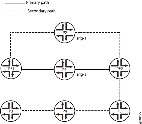
この例では:
-
PE1はingressルーターで、PE2はegressルーターです。
-
P1、P2、およびP3、P4、およびP5はトランジットルーターです。
-
P1は、PE1イングレスルーターとPE2エグレスルーターの両方への直接プライマリパス接続を持っています。
-
P2は、PE1およびPE2への直接セカンダリパス接続を持っています。
-
P3には、PE1への直接セカンダリパス接続と、P4およびP5を経由してPE2への間接セカンダリパスがあります。
-
P4には、PE1からP3、およびPE2からP5への間接的なセカンダリパスがあります。
-
P5 には、P4 と P3 を経由して PE1 に至る間接パスと、PE2 への直接セカンダリ パスがあります。
-
OSPFは、内部ゲートウェイプロトコル(IGP)としてすべてのルーターで設定されています。SRLGは7つのルーターすべてに設定されています。プライマリパスには、SRLG srlg-aが含まれます。スタンバイセカンダリパスの場合、リンクP2>PE2はSRLG srlg-aに属します。有効なリンクメトリックには、 srlg-cost が10を加えると11になります。したがって、計算されるセカンダリパスは、CSPFリンクメトリックが4のPE1>P3>P4>P5>PE2となります。
トポロジー
設定
CLIクイックコンフィグレーション
この例のセクションをすばやく設定するには、以下のコマンドをコピーしてテキスト ファイルに貼り付け、改行を削除して、ネットワーク構成に合わせて必要な詳細を変更し、コマンドを [edit] 階層レベルのCLIにコピー アンド ペーストします。
ルーターPE1
set interfaces ge-0/0/1 unit 0 family inet address 192.168.12.1/24
set interfaces ge-0/0/1 unit 0 family mpls
set interfaces ge-0/0/2 unit 0 family inet address 192.168.13.1/24
set interfaces ge-0/0/2 unit 0 family mpls
set interfaces ge-0/0/3 unit 0 family inet address 192.168.14.1/24
set interfaces ge-0/0/3 unit 0 family mpls
set interfaces lo0 unit 0 family inet address 10.255.0.1/32
set routing-options srlg srlg-a srlg-value 101
set routing-options srlg srlg-a srlg-cost 10
set protocols rsvp interface ge-0/0/1.0
set protocols rsvp interface ge-0/0/2.0
set protocols rsvp interface ge-0/0/3.0
set protocols mpls optimize-timer 120
set protocols mpls label-switched-path pe1-pe2 to 10.255.0.7
set protocols mpls label-switched-path pe1-pe2 primary via-p1
set protocols mpls label-switched-path pe1-pe2 secondary path2 standby
set protocols mpls path via-p1 10.255.0.2 strict
set protocols mpls path path2
set protocols mpls interface ge-0/0/1.0
set protocols mpls interface ge-0/0/2.0
set protocols mpls interface ge-0/0/3.0
set protocols ospf traffic-engineering
set protocols ospf area 0.0.0.0 interface ge-0/0/1.0
set protocols ospf area 0.0.0.0 interface ge-0/0/2.0
set protocols ospf area 0.0.0.0 interface ge-0/0/3.0
set protocols ospf area 0.0.0.0 interface lo0.0
ルーターP1
set interfaces ge-0/0/1 unit 0 family inet address 192.168.12.2/24
set interfaces ge-0/0/1 unit 0 family mpls
set interfaces ge-0/0/2 unit 0 family inet address 192.168.27.2/24
set interfaces ge-0/0/2 unit 0 family mpls
set interfaces lo0 unit 0 family inet address 10.255.0.2/32
set routing-options srlg srlg-a srlg-value 101
set routing-options srlg srlg-a srlg-cost 10
set protocols rsvp interface ge-0/0/1.0
set protocols rsvp interface ge-0/0/2.0
set protocols mpls interface ge-0/0/1.0
set protocols mpls interface ge-0/0/2.0 srlg srlg-a
set protocols ospf traffic-engineering
set protocols ospf area 0.0.0.0 interface ge-0/0/1.0
set protocols ospf area 0.0.0.0 interface ge-0/0/2.0
set protocols ospf area 0.0.0.0 interface lo0.0
ルーターP2
set interfaces ge-0/0/1 unit 0 family inet address 192.168.13.3/24
set interfaces ge-0/0/1 unit 0 family mpls
set interfaces ge-0/0/2 unit 0 family inet address 192.168.37.3/24
set interfaces ge-0/0/2 unit 0 family mpls
set interfaces lo0 unit 0 family inet address 10.255.0.3/32
set routing-options srlg srlg-a srlg-value 101
set routing-options srlg srlg-a srlg-cost 10
set protocols rsvp interface ge-0/0/1.0
set protocols rsvp interface ge-0/0/2.0
set protocols mpls interface ge-0/0/1.0
set protocols mpls interface ge-0/0/2.0 srlg srlg-a
set protocols ospf traffic-engineering
set protocols ospf area 0.0.0.0 interface ge-0/0/1.0
set protocols ospf area 0.0.0.0 interface ge-0/0/2.0
set protocols ospf area 0.0.0.0 interface lo0.0
ルーターP3
set interfaces ge-0/0/1 unit 0 family inet address 192.168.14.4/24
set interfaces ge-0/0/1 unit 0 family mpls
set interfaces ge-0/0/2 unit 0 family inet address 192.168.45.4/24
set interfaces ge-0/0/2 unit 0 family mpls
set interfaces lo0 unit 0 family inet address 10.255.0.4/32
set routing-options srlg srlg-a srlg-value 101
set routing-options srlg srlg-a srlg-cost 10
set protocols rsvp interface ge-0/0/1.0
set protocols rsvp interface ge-0/0/2.0
set protocols mpls interface ge-0/0/1.0
set protocols mpls interface ge-0/0/2.0
set protocols ospf traffic-engineering
set protocols ospf area 0.0.0.0 interface ge-0/0/1.0
set protocols ospf area 0.0.0.0 interface ge-0/0/2.0
set protocols ospf area 0.0.0.0 interface lo0.0
ルーターP4
set interfaces ge-0/0/1 unit 0 family inet address 192.168.45.5/24
set interfaces ge-0/0/1 unit 0 family mpls
set interfaces ge-0/0/2 unit 0 family inet address 192.168.56.5/24
set interfaces ge-0/0/2 unit 0 family mpls
set interfaces lo0 unit 0 family inet address 10.255.0.5/32
set routing-options srlg srlg-a srlg-value 101
set routing-options srlg srlg-a srlg-cost 10
set protocols rsvp interface ge-0/0/1.0
set protocols rsvp interface ge-0/0/2.0
set protocols mpls interface ge-0/0/1.0
set protocols mpls interface ge-0/0/2.0
set protocols ospf traffic-engineering
set protocols ospf area 0.0.0.0 interface ge-0/0/1.0
set protocols ospf area 0.0.0.0 interface ge-0/0/2.0
set protocols ospf area 0.0.0.0 interface lo0.0
ルーターP5
set interfaces ge-0/0/1 unit 0 family inet address 192.168.56.6/24
set interfaces ge-0/0/1 unit 0 family mpls
set interfaces ge-0/0/2 unit 0 family inet address 192.168.67.6/24
set interfaces ge-0/0/2 unit 0 family mpls
set interfaces lo0 unit 0 family inet address 10.255.0.6/32
set routing-options srlg srlg-a srlg-value 101
set routing-options srlg srlg-a srlg-cost 10
set protocols rsvp interface ge-0/0/1.0
set protocols rsvp interface ge-0/0/2.0
set protocols mpls interface ge-0/0/1.0
set protocols mpls interface ge-0/0/2.0
set protocols ospf traffic-engineering
set protocols ospf area 0.0.0.0 interface ge-0/0/1.0
set protocols ospf area 0.0.0.0 interface ge-0/0/2.0
set protocols ospf area 0.0.0.0 interface lo0.0
ルーターPE2
set interfaces ge-0/0/1 unit 0 family inet address 192.168.27.7/24
set interfaces ge-0/0/1 unit 0 family mpls
set interfaces ge-0/0/2 unit 0 family inet address 192.168.37.7/24
set interfaces ge-0/0/2 unit 0 family mpls
set interfaces ge-0/0/3 unit 0 family inet address 192.168.67.7/24
set interfaces ge-0/0/3 unit 0 family mpls
set interfaces lo0 unit 0 family inet address 10.255.0.7/32
set routing-options srlg srlg-a srlg-value 101
set routing-options srlg srlg-a srlg-cost 10
set protocols rsvp interface ge-0/0/1.0
set protocols rsvp interface ge-0/0/2.0
set protocols rsvp interface ge-0/0/3.0
set protocols mpls interface ge-0/0/1.0
set protocols mpls interface ge-0/0/2.0
set protocols mpls interface ge-0/0/3.0
set protocols ospf traffic-engineering
set protocols ospf area 0.0.0.0 interface ge-0/0/1.0
set protocols ospf area 0.0.0.0 interface ge-0/0/2.0
set protocols ospf area 0.0.0.0 interface ge-0/0/3.0
set protocols ospf area 0.0.0.0 interface lo0.0
手順
ステップバイステップの手順
次の例では、設定階層のさまざまなレベルに移動する必要があります。CLI のナビゲーションについては、 Junos OS CLI ユーザーガイドを参照してください。
ingressルーターPE1を設定するには:
-
デバイスインターフェイスを設定します。
[edit interfaces]user@PE1# set ge-0/0/1 unit 0 family inet address 192.168.12.1/24 user@PE1# set ge-0/0/1 unit 0 family mpls user@PE1# set ge-0/0/2 unit 0 family inet address 192.168.13.1/24 user@PE1# set ge-0/0/2 unit 0 family mpls user@PE1# set ge-0/0/3 unit 0 family inet address 192.168.14.1/24 user@PE1# set ge-0/0/3 unit 0 family mpls user@PE1# set lo0 unit 0 family inet address 10.255.0.1/32 -
インターフェイスに OSPF を設定します。
[edit protocols ospf]user@PE1# set traffic-engineering user@PE1# set area 0.0.0.0 interface ge-0/0/1.0 user@PE1# set area 0.0.0.0 interface ge-0/0/2.0 user@PE1# set area 0.0.0.0 interface ge-0/0/3.0 user@PE1# set area 0.0.0.0 interface lo0.0 -
SRLG 定義を設定します。
[edit routing-options]user@PE1# set srlg srlg-a srlg-value 101 user@PE1# set srlg srlg-a srlg-cost 10 -
MPLSとLSPを設定します。
[edit protocols mpls]user@PE1# set interface ge-0/0/1.0 user@PE1# set interface ge-0/0/2.0 user@PE1# set interface ge-0/0/3.0 user@PE1# set optimize-timer 120 user@PE1# set label-switched-path pe1-pe2 to 10.255.0.7 user@PE1# set label-switched-path pe1-pe2 primary via-p1 user@PE1# set label-switched-path pe1-pe2 secondary path2 standby user@PE1# set path via-p1 10.255.0.2 strict user@PE1# set path path2 -
インターフェイスでRSVPを有効にします。
[edit protocols rsvp]user@PE1# set interface ge-0/0/1.0 user@PE1# set interface ge-0/0/2.0 user@PE1# set interface ge-0/0/3.0
結果
設定モードから、 show interfaces、 show protocols ospf、 show routing-options、 show protocols mpls、 show protocols rsvp コマンドを入力して設定を確認します。出力に意図した設定が表示されない場合は、この例の手順を繰り返して設定を修正します。
user@PE1# show interfaces
interfaces {
    ge-0/0/1 {
        unit 0 {
            family inet {
                address 192.168.12.1/24;
            }
            family mpls;
        }
    }
    ge-0/0/2 {
        unit 0 {
            family inet {
                address 192.168.13.1/24;
            }
            family mpls;
        }
    }
    ge-0/0/3 {
        unit 0 {
            family inet {
                address 192.168.14.1/24;
            }
            family mpls;
        }
    }
    lo0 {
        unit 0 {
            family inet {
                address 10.255.0.1/32;
            }
        }
    }
}
user@PE1# show protocols ospf
traffic-engineering;
area 0.0.0.0 {
    interface ge-0/0/1.0;;
    interface ge-0/0/2.0;
    interface ge-0/0/3.0;
    interface lo0.0;
}
user@PE1# show protocols mpls
optimize-timer 120;
label-switched-path pe1-pe2 {
    to 10.255.0.7;
    primary via-p1;
    secondary path2 {
        standby;
    }
}
path via-p1 {
    10.255.0.2 strict;
}
path path2;
interface ge-0/0/1.0;
interface ge-0/0/2.0;
interface ge-0/0/3.0;
user@PE1# show protocols rsvp
interface ge-0/0/1.0;
interface ge-0/0/2.0;
interface ge-0/0/3.0;
user@PE1# show routing-options
routing-options {
    srlg {
        srlg-a {
            srlg-value 101;
            srlg-cost 10;
        }
    }
}
デバイスの設定が完了したら、設定モードから commit を入力します。
各ルーターの適切なインターフェイス名、アドレス、およびその他のパラメータを変更した後、IGPドメイン内のすべてのジュニパーネットワークスルーターに対してこの手順を繰り返します。
検証
設定が正常に機能していることを確認します。
SRLG 定義の検証
目的
SRLG から値へのマッピングと SRLG コストを検証します。
アクション
user@PE1> show mpls srlg

SRLG             Value      Cost
srlg-a             101        10
TE-Link SRLG の検証
目的
トラフィック制御リンクSRLGの関連付けを確認します。
アクション
user@PE1> show ted link detail
...
10.255.0.2->192.168.27.7-1, Local: 192.168.27.2, Remote: 0.0.0.0
  Local interface index: 0, Remote interface index: 0
  LocalPath: 1, Metric: 1, StaticBW: 1000Mbps, AvailBW: 1000Mbps
      Color: 0 <none>
  SRLGs: srlg-a
  localBW [0] 0bps  [1] 0bps  [2] 0bps  [3] 0bps
  localBW [4] 0bps  [5] 0bps  [6] 0bps  [7] 0bps

...
10.255.0.3->192.168.37.7-1, Local: 192.168.37.3, Remote: 0.0.0.0
  Local interface index: 0, Remote interface index: 0
  LocalPath: 0, Metric: 1, StaticBW: 1000Mbps, AvailBW: 1000Mbps
      Color: 0 <none>
  SRLGs: srlg-a
  localBW [0] 0bps  [1] 0bps  [2] 0bps  [3] 0bps
  localBW [4] 0bps  [5] 0bps  [6] 0bps  [7] 0bps

...
意味
リンクP1-PE2とP2-PE2は、SRLG srlg-aに関連付けられています。
スタンバイセカンダリパスの検証
目的
SRLG リンク コストと、スタンバイ セカンダリ パス リンクの CSPF 計算への影響を確認します。
アクション
user@PE1> show mpls lsp ingress extensive
Ingress LSP: 1 sessions

10.255.0.7
  From: 10.255.0.1, State: Up, ActiveRoute: 0, LSPname: pe1-pe2
  ActivePath: via-p1 (primary)
  LSPtype: Static Configured
  LoadBalance: Random
  Encoding type: Packet, Switching type: Packet, GPID: IPv4
 *Primary   via-p1           State: Up
    Priorities: 7 0
    OptimizeTimer: 120
    SmartOptimizeTimer: 180
    SRLG: srlg-a
    Reoptimization in 110 second(s).
    Computed ERO (S [L] denotes strict [loose] hops): (CSPF metric: 2)
 192.168.12.2 S 192.168.27.7 S
    Received RRO (ProtectionFlag 1=Available 2=InUse 4=B/W 8=Node 10=SoftPreempt 20=Node-ID):
          192.168.12.2 192.168.27.7
    7 Oct 13 15:17:11.310 CSPF: computation result ignored, new path no benefit
    6 Oct 13 15:15:14.959 Selected as active path
    5 Oct 13 15:15:14.958 Record Route:  192.168.12.2 192.168.27.7
    4 Oct 13 15:15:14.954 Up
    3 Oct 13 15:15:14.793 Originate Call
    2 Oct 13 15:15:14.793 CSPF: computation result accepted  192.168.12.2 192.168.27.7
    1 Oct 13 15:14:46.214 CSPF failed: no route toward 10.255.0.2
  Standby   path2            State: Up
    Priorities: 7 0
    OptimizeTimer: 120
    SmartOptimizeTimer: 180
    Reoptimization in 115 second(s).
    Computed ERO (S [L] denotes strict [loose] hops): (CSPF metric: 4)
 192.168.14.4 S 192.168.45.5 S 192.168.56.6 S 192.168.67.7 S
    Received RRO (ProtectionFlag 1=Available 2=InUse 4=B/W 8=Node 10=SoftPreempt 20=Node-ID):
          192.168.14.4 192.168.45.5 192.168.56.6 192.168.67.7
   10 Oct 13 15:17:11.929 Record Route:  192.168.14.4 192.168.45.5 192.168.56.6 192.168.67.7
    9 Oct 13 15:17:11.929 Up
    8 Oct 13 15:17:11.729 Originate Call
    7 Oct 13 15:17:11.729 Clear Call
    6 Oct 13 15:17:11.729 CSPF: computation result accepted  192.168.14.4 192.168.45.5 192.168.56.6 192.168.67.7
    5 Oct 13 15:17:11.729 CSPF: Reroute due to re-optimization
    4 Oct 13 15:15:14.984 Record Route:  192.168.13.3 192.168.37.7
    3 Oct 13 15:15:14.984 Up
    2 Oct 13 15:15:14.830 Originate Call
    1 Oct 13 15:15:14.830 CSPF: computation result accepted  192.168.13.3 192.168.37.7
  Created: Thu Oct 13 15:13:46 2011
Total 1 displayed, Up 1, Down 0
意味
スタンバイセカンダリパスを確認します。P2>PE2の実効リンクコストは11です( srlg-cost は10)。CSPF は、セカンダリ パスを PE1>P3>P4>P5>PE2 として計算し、CSPF リンク メトリックは 4 です。
例:セカンダリLSPのSRLGリンクを完全に除外する
この例では、セカンダリ LSP(共有リスク リンク グループ)リンクを除外する exclude-srlg オプションを設定する方法を示しています。
要件
この例では、以下のハードウェアおよびソフトウェアコンポーネントを使用しています。
-
MXシリーズデバイス
-
すべてのデバイスで実行されている Junos OS リリース 11.4 以降
概要
セカンダリ パスとプライマリ パスを共通の SRLG から完全に切り離す必要がある重要なリンクでは、オプションで [edit protocols mpls] または [edit protocols mpls label-switched-path path-name] 階層レベルで exclude-srlg ステートメントを設定することができます。論理システムの場合、edit logical-systems protocols mpls [edit logical-systems logical-system-name protocols mpls label-switched-path path-name]階層レベルでexclude-srlgステートメントを設定します。
exclude-srlgが設定されている場合、CSPF(制約付き最短パスファースト)アルゴリズムは、プライマリパス内のSRLGのセットに属するリンクを除外します。exclude-srlgが設定されておらず、リンクがプライマリパスのSRLGのセットに属している場合、CSPFはSRLGコストをメトリックに追加しますが、パスを計算するためにリンクを受け入れます。
この例では、PE1はingressルーターで、PE2はegressルーターです。P1、P2、およびP3、P4、およびP5はトランジットルーターです。OSPFは、内部ゲートウェイプロトコル(IGP)としてすべてのルーターで設定されています。SRLGは7つのルーターすべてに設定されています。プライマリパスには、SRLG srlg-aが含まれます。スタンバイセカンダリパスの場合、リンクP2>PE2はSRLG srlg-aに属します。 exclude-srlg が設定されているため、リンクがSRLG srlg-aに属しているため、CSPFはリンクP2>PE2を拒否します。したがって、計算されるスタンバイセカンダリパスはPE1>P3>P4>P5>PE2となります。
トポロジー
設定
CLIクイックコンフィグレーション
この例のセクションをすばやく設定するには、以下のコマンドをコピーしてテキスト ファイルに貼り付け、改行を削除して、ネットワーク構成に合わせて必要な詳細を変更し、コマンドを [edit] 階層レベルのCLIにコピー アンド ペーストします。
ルーターPE1
set interfaces ge-0/0/1 unit 0 family inet address 192.168.12.1/24
set interfaces ge-0/0/1 unit 0 family mpls
set interfaces ge-0/0/2 unit 0 family inet address 192.168.13.1/24
set interfaces ge-0/0/2 unit 0 family mpls
set interfaces ge-0/0/3 unit 0 family inet address 192.168.14.1/24
set interfaces ge-0/0/3 unit 0 family mpls
set interfaces lo0 unit 0 family inet address 10.255.0.1/32
set routing-options srlg srlg-a srlg-value 101
set protocols rsvp interface ge-0/0/1.0
set protocols rsvp interface ge-0/0/2.0
set protocols rsvp interface ge-0/0/3.0
set protocols mpls optimize-timer 120
set protocols mpls exclude-srlg
set protocols mpls label-switched-path pe1-pe2 to 10.255.0.7
set protocols mpls label-switched-path pe1-pe2 primary via-p1
set protocols mpls label-switched-path pe1-pe2 secondary path2 standby
set protocols mpls path via-p1 10.255.0.2 strict
set protocols mpls path path2
set protocols mpls interface ge-0/0/1.0
set protocols mpls interface ge-0/0/2.0
set protocols mpls interface ge-0/0/3.0
set protocols ospf traffic-engineering
set protocols ospf area 0.0.0.0 interface ge-0/0/1.0
set protocols ospf area 0.0.0.0 interface ge-0/0/2.0
set protocols ospf area 0.0.0.0 interface ge-0/0/3.0
set protocols ospf area 0.0.0.0 interface lo0.0
手順
ステップバイステップの手順
次の例では、設定階層のさまざまなレベルに移動する必要があります。CLI のナビゲーションについては、 Junos OS CLI ユーザーガイドを参照してください。
-
デバイスインターフェイスを設定します。
[edit interfaces]user@PE1# set ge-0/0/1 unit 0 family inet address 192.168.12.1/24 user@PE1# set ge-0/0/1 unit 0 family mpls user@PE1# set ge-0/0/2 unit 0 family inet address 192.168.13.1/24 user@PE1# set ge-0/0/2 unit 0 family mpls user@PE1# set ge-0/0/3 unit 0 family inet address 192.168.14.1/24 user@PE1# set ge-0/0/3 unit 0 family mpls user@PE1# set lo0 unit 0 family inet address 10.255.0.1/32 -
インターフェイスに OSPF を設定します。
[edit protocols ospf]user@PE1# set traffic-engineering user@PE1# set area 0.0.0.0 interface ge-0/0/1.0 user@PE1# set area 0.0.0.0 interface ge-0/0/2.0 user@PE1# set area 0.0.0.0 interface ge-0/0/3.0 user@PE1# set area 0.0.0.0 interface lo0.0 -
SRLG 定義を設定します。
[edit routing-options]user@PE1# set routing-options srlg srlg-a srlg-value 101 -
MPLSとLSPを設定します。
[edit protocols mpls]user@PE1# set interface ge-0/0/1.0 user@PE1# set interface ge-0/0/2.0 user@PE1# set interface ge-0/0/3.0 user@PE1# set optimize-timer 120 user@PE1# set exclude-srlg user@PE1# set label-switched-path pe1-pe2 to 10.255.0.7 user@PE1# set label-switched-path pe1-pe2 primary via-p1 user@PE1# set label-switched-path pe1-pe2 secondary path2 standby user@PE1# set path via-p1 10.255.0.2 strict user@PE1# set path path2 -
セカンダリパスのリンクをプライマリLSPパスから完全に切り離した状態に強制的に維持するように
exclude-srlgステートメントを設定します。user@PE1 set protocols mpls exclude-srlg
-
インターフェイスでRSVPを有効にします。
[edit protocols rsvp]user@PE1# set interface ge-0/0/1.0 user@PE1# set interface ge-0/0/2.0 user@PE1# set interface ge-0/0/3.0
結果
設定モードから、 show interfaces, show protocols ospf、 show routing-options、 show protocols mpls、および show protocols rsvp コマンドを入力して設定を確認します。出力に意図した設定が表示されない場合は、この例の手順を繰り返して設定を修正します。
user@PE1# show interfaces
interfaces {
    ge-0/0/1 {
        unit 0 {
            family inet {
                address 192.168.12.1/24;
            }
            family mpls;
        }
    }
    ge-0/0/2 {
        unit 0 {
            family inet {
                address 192.168.13.1/24;
            }
            family mpls;
        }
    }
    ge-0/0/3 {
        unit 0 {
            family inet {
                address 192.168.14.1/24;
            }
            family mpls;
        }
    }
    lo0 {
        unit 0 {
            family inet {
                address 10.255.0.1/32;
            }
        }
    }
}
user@PE1# show protocols ospf
traffic-engineering;
area 0.0.0.0 {
    interface ge-0/0/1.0;;
    interface ge-0/0/2.0;
    interface ge-0/0/3.0;
    interface lo0.0;
}
user@PE1# show protocols mpls
optimize-timer 120;
label-switched-path pe1-pe2 {
    to 10.255.0.7;
    primary via-p1;
    secondary path2 {
        standby;
    }
}
path via-p1 {
    10.255.0.2 strict;
}
path path2;
interface ge-0/0/1.0;
interface ge-0/0/2.0;
interface ge-0/0/3.0;
user@PE1# show protocols rsvp
interface ge-0/0/1.0;
interface ge-0/0/2.0;
interface ge-0/0/3.0;
user@PE1# show routing-options
routing-options {
    srlg {
        srlg-a srlg-value 101;
    }
}
デバイスの設定が完了したら、設定モードから commit を入力します。
各ルーターの適切なインターフェイス名、アドレス、およびその他のパラメータを変更した後、IGPドメイン内のすべてのジュニパーネットワークスルーターに対してこの手順を繰り返します。
検証
設定が正常に機能していることを確認します。
LSP のセカンダリ パス リンクの検証
目的
セカンダリパスのリンクがプライマリパスから完全にディスジョイントされていることを確認します。
アクション
user@PE1> show mpls lsp detail
Ingress LSP: 1 sessions

10.255.0.7
  From: 10.255.0.1, State: Up, ActiveRoute: 0, LSPname: pe1-pe2
  ActivePath: via-p1 (primary)
  LSPtype: Static Configured
  LoadBalance: Random
  Encoding type: Packet, Switching type: Packet, GPID: IPv4
 *Primary   via-p1           State: Up
    Priorities: 7 0
    OptimizeTimer: 120
    SmartOptimizeTimer: 180
    SRLG: srlg-a
    Reoptimization in 77 second(s).
    Computed ERO (S [L] denotes strict [loose] hops): (CSPF metric: 2)
 192.168.12.2 S 192.168.27.7 S
    Received RRO (ProtectionFlag 1=Available 2=InUse 4=B/W 8=Node 10=SoftPreempt 20=Node-ID):
          192.168.12.2 192.168.27.7
  Standby   path2            State: Up
    Priorities: 7 0
    OptimizeTimer: 120
    SmartOptimizeTimer: 180
    Reoptimization in 106 second(s).
    Computed ERO (S [L] denotes strict [loose] hops): (CSPF metric: 4)
 192.168.14.4 S 192.168.45.5 S 192.168.56.6 S 192.168.67.7 S
    Received RRO (ProtectionFlag 1=Available 2=InUse 4=B/W 8=Node 10=SoftPreempt 20=Node-ID):
          192.168.14.4 192.168.45.5 192.168.56.6 192.168.67.7
Total 1 displayed, Up 1, Down 0

Link P1->PE2: SRLG srlg-a
Link P2->PE2: SRLG srlg-a

Primary path:      PE1-P1-PE2       (CSPF metric: 2)
Standby secondary: PE1-P3-P4-P5-PE2 (CSPF metric: 4)
意味
プライマリパスにはSRLG srlg-aが含まれます。スタンバイセカンダリパスの場合、リンクP2>PE2はSRLG srlg-aに属します。リンクがSRLG srlg-aに属しているため、CSPFはリンクP2>PE2を拒否します。
例:リンク保護を使用した SRLG の設定
この例では、 exclude-srlg オプションを使用せずにリンク保護付きSRLGを設定する方法を示しています。
要件
この例では、以下のハードウェアおよびソフトウェアコンポーネントを使用しています。
-
MXシリーズデバイス
-
すべてのデバイスで実行されている Junos OS リリース 11.4 以降
概要
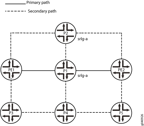
この例では、PE1はingressルーターで、PE2はegressルーターです。P1、P2、およびP3、P4、およびP5はトランジットルーターです。OSPFは、内部ゲートウェイプロトコル(IGP)としてすべてのルーターで設定されています。SRLGは7つのルーターすべてに設定されています。リンクP1>PE2(プライマリパス)とリンクP2>PE2は、SRLG srlg-aに属します。
link-protectionステートメントを含めることで、インターフェイスP1>PE2のリンク保護を設定します。
リンクP1>PE2とP2>PE2でSRLG srlg-aが設定されている場合、バイパスはより長いパスP1>P4>P5>PE2を取り、srlg-aのSRLGコストが追加されるため、リンクP2>PE2は選択されません。
トポロジー
設定
CLIクイックコンフィグレーション
この例のセクションをすばやく設定するには、次のコマンドをコピーしてテキスト ファイルに貼り付け、改行を削除して、ネットワーク構成に合わせて必要な詳細を変更してから、コマンドを [edit] 階層レベルのCLIにコピー アンド ペーストします。
ルーターPE1
set interfaces ge-0/0/1 unit 0 family inet address 192.168.12.1/24
set interfaces ge-0/0/1 unit 0 family mpls
set interfaces ge-0/0/2 unit 0 family inet address 192.168.13.1/24
set interfaces ge-0/0/2 unit 0 family mpls
set interfaces ge-0/0/3 unit 0 family inet address 192.168.14.1/24
set interfaces ge-0/0/3 unit 0 family mpls
set interfaces lo0 unit 0 family inet address 10.255.0.1/32
set routing-options srlg srlg-a srlg-value 101
set routing-options srlg srlg-a srlg-cost 10
set protocols rsvp interface ge-0/0/1.0
set protocols rsvp interface ge-0/0/2.0
set protocols rsvp interface ge-0/0/3.0
set protocols mpls optimize-timer 120
set protocols mpls label-switched-path pe1-pe2 to 10.255.0.7
set protocols mpls label-switched-path pe1-pe2 link-protection
set protocols mpls label-switched-path pe1-pe2 primary via-p1
set protocols mpls label-switched-path pe1-pe2 secondary path2 standby
set protocols mpls path via-p1 10.255.0.2 strict
set protocols mpls path path2
set protocols mpls interface ge-0/0/1.0
set protocols mpls interface ge-0/0/2.0
set protocols mpls interface ge-0/0/3.0
set protocols ospf traffic-engineering
set protocols ospf area 0.0.0.0 interface ge-0/0/1.0
set protocols ospf area 0.0.0.0 interface ge-0/0/2.0
set protocols ospf area 0.0.0.0 interface ge-0/0/3.0
set protocols ospf area 0.0.0.0 interface lo0.0
ルーターP1
set interfaces ge-0/0/1 unit 0 family inet address 192.168.12.2/24
set interfaces ge-0/0/1 unit 0 family mpls
set interfaces ge-0/0/2 unit 0 family inet address 192.168.27.2/24
set interfaces ge-0/0/2 unit 0 family mpls
set interfaces ge-0/0/3 unit 0 family inet address 192.168.23.2/24
set interfaces ge-0/0/3 unit 0 family mpls
set interfaces ge-0/0/4 unit 0 family inet address 192.168.25.2/24
set interfaces ge-0/0/4 unit 0 family mpls
set interfaces lo0 unit 0 family inet address 10.255.0.2/32
set routing-options srlg srlg-a srlg-value 101
set routing-options srlg srlg-a srlg-cost 10
set protocols rsvp interface ge-0/0/1.0
set protocols rsvp interface ge-0/0/2.0 link-protection
set protocols rsvp interface ge-0/0/3.0
set protocols rsvp interface ge-0/0/4.0
set protocols mpls interface ge-0/0/1.0
set protocols mpls interface ge-0/0/2.0 srlg srlg-a
set protocols mpls interface ge-0/0/3.0
set protocols mpls interface ge-0/0/4.0
set protocols ospf traffic-engineering
set protocols ospf area 0.0.0.0 interface ge-0/0/1.0
set protocols ospf area 0.0.0.0 interface ge-0/0/2.0
set protocols ospf area 0.0.0.0 interface ge-0/0/3.0
set protocols ospf area 0.0.0.0 interface ge-0/0/4.0
set protocols ospf area 0.0.0.0 interface lo0.0
ルーターP2
set interfaces ge-0/0/1 unit 0 family inet address 192.168.13.3/24
set interfaces ge-0/0/1 unit 0 family mpls
set interfaces ge-0/0/2 unit 0 family inet address 192.168.37.3/24
set interfaces ge-0/0/2 unit 0 family mpls
set interfaces ge-0/0/3 unit 0 family inet address 192.168.23.3/24
set interfaces ge-0/0/3 unit 0 family mpls
set interfaces lo0 unit 0 family inet address 10.255.0.3/32
set routing-options srlg srlg-a srlg-value 101
set routing-options srlg srlg-a srlg-cost 10
set protocols rsvp interface ge-0/0/1.0
set protocols rsvp interface ge-0/0/2.0
set protocols rsvp interface ge-0/0/3.0
set protocols mpls interface ge-0/0/1.0
set protocols mpls interface ge-0/0/2.0 srlg srlg-a
set protocols mpls interface ge-0/0/3.0
set protocols ospf traffic-engineering
set protocols ospf area 0.0.0.0 interface ge-0/0/1.0
set protocols ospf area 0.0.0.0 interface ge-0/0/2.0
set protocols ospf area 0.0.0.0 interface ge-0/0/3.0
set protocols ospf area 0.0.0.0 interface lo0.0
ルーターP3
set interfaces ge-0/0/1 unit 0 family inet address 192.168.14.4/24
set interfaces ge-0/0/1 unit 0 family mpls
set interfaces ge-0/0/2 unit 0 family inet address 192.168.45.4/24
set interfaces ge-0/0/2 unit 0 family mpls
set interfaces lo0 unit 0 family inet address 10.255.0.4/32
set routing-options srlg srlg-a srlg-value 101
set routing-options srlg srlg-a srlg-cost 10
set protocols rsvp interface ge-0/0/1.0
set protocols rsvp interface ge-0/0/2.0
set protocols mpls interface ge-0/0/1.0
set protocols mpls interface ge-0/0/2.0
set protocols ospf traffic-engineering
set protocols ospf area 0.0.0.0 interface ge-0/0/1.0
set protocols ospf area 0.0.0.0 interface ge-0/0/2.0
set protocols ospf area 0.0.0.0 interface lo0.0
ルーターP4
set interfaces ge-0/0/1 unit 0 family inet address 192.168.45.5/24
set interfaces ge-0/0/1 unit 0 family mpls
set interfaces ge-0/0/2 unit 0 family inet address 192.168.56.5/24
set interfaces ge-0/0/2 unit 0 family mpls
set interfaces ge-0/0/3 unit 0 family inet address 192.168.25.5/24
set interfaces ge-0/0/3 unit 0 family mpls
set interfaces lo0 unit 0 family inet address 10.255.0.5/32
set routing-options srlg srlg-a srlg-value 101
set routing-options srlg srlg-a srlg-cost 10
set protocols rsvp interface ge-0/0/1.0
set protocols rsvp interface ge-0/0/2.0
set protocols rsvp interface ge-0/0/3.0
set protocols mpls interface ge-0/0/1.0
set protocols mpls interface ge-0/0/2.0
set protocols mpls interface ge-0/0/3.0
set protocols ospf traffic-engineering
set protocols ospf area 0.0.0.0 interface ge-0/0/1.0
set protocols ospf area 0.0.0.0 interface ge-0/0/2.0
set protocols ospf area 0.0.0.0 interface ge-0/0/3.0
set protocols ospf area 0.0.0.0 interface lo0.0
ルーターP5
set interfaces ge-0/0/1 unit 0 family inet address 192.168.56.6/24
set interfaces ge-0/0/1 unit 0 family mpls
set interfaces ge-0/0/2 unit 0 family inet address 192.168.67.6/24
set interfaces ge-0/0/2 unit 0 family mpls
set interfaces lo0 unit 0 family inet address 10.255.0.6/32
set routing-options srlg srlg-a srlg-value 101
set routing-options srlg srlg-a srlg-cost 10
set protocols rsvp interface ge-0/0/1.0
set protocols rsvp interface ge-0/0/2.0
set protocols mpls interface ge-0/0/1.0
set protocols mpls interface ge-0/0/2.0
set protocols ospf traffic-engineering
set protocols ospf area 0.0.0.0 interface ge-0/0/1.0
set protocols ospf area 0.0.0.0 interface ge-0/0/2.0
set protocols ospf area 0.0.0.0 interface lo0.0
ルーターPE2
set interfaces ge-0/0/1 unit 0 family inet address 192.168.27.7/24
set interfaces ge-0/0/1 unit 0 family mpls
set interfaces ge-0/0/2 unit 0 family inet address 192.168.37.7/24
set interfaces ge-0/0/2 unit 0 family mpls
set interfaces ge-0/0/3 unit 0 family inet address 192.168.67.7/24
set interfaces ge-0/0/3 unit 0 family mpls
set interfaces lo0 unit 0 family inet address 10.255.0.7/32
set routing-options srlg srlg-a srlg-value 101
set routing-options srlg srlg-a srlg-cost 10
set protocols rsvp interface ge-0/0/1.0
set protocols rsvp interface ge-0/0/2.0
set protocols rsvp interface ge-0/0/3.0
set protocols mpls interface ge-0/0/1.0
set protocols mpls interface ge-0/0/2.0
set protocols mpls interface ge-0/0/3.0
set protocols ospf traffic-engineering
set protocols ospf area 0.0.0.0 interface ge-0/0/1.0
set protocols ospf area 0.0.0.0 interface ge-0/0/2.0
set protocols ospf area 0.0.0.0 interface ge-0/0/3.0
set protocols ospf area 0.0.0.0 interface lo0.0
デバイスPE1の設定
ステップバイステップの手順
次の例では、設定階層のさまざまなレベルに移動する必要があります。CLI のナビゲーションについては、 Junos OS CLI ユーザーガイドを参照してください。
ingressルーターPE1を設定するには:
-
デバイスインターフェイスを設定します。
[edit interfaces]user@PE1# set ge-0/0/1 unit 0 family inet address 192.168.12.1/24 user@PE1# set ge-0/0/1 unit 0 family mpls user@PE1# set ge-0/0/2 unit 0 family inet address 192.168.13.1/24 user@PE1# set ge-0/0/2 unit 0 family mpls user@PE1# set ge-0/0/3 unit 0 family inet address 192.168.14.1/24 user@PE1# set ge-0/0/3 unit 0 family mpls user@PE1# set lo0 unit 0 family inet address 10.255.0.1/32 -
インターフェイスに OSPF を設定します。
[edit protocols ospf]user@PE1# set traffic-engineering user@PE1# set area 0.0.0.0 interface ge-0/0/1.0 user@PE1# set area 0.0.0.0 interface ge-0/0/2.0 user@PE1# set area 0.0.0.0 interface ge-0/0/3.0 user@PE1# set area 0.0.0.0 interface lo0.0 -
SRLG 定義を設定します。
[edit routing-options]user@PE1# set srlg srlg-a srlg-value 101 user@PE1# set srlg srlg-a srlg-cost 10 -
MPLSとLSPを設定し、
pe1-pe2LSPのリンク保護を設定します。[edit protocols mpls]user@PE1# set interface ge-0/0/1.0 user@PE1# set interface ge-0/0/2.0 user@PE1# set interface ge-0/0/3.0 user@PE1# set optimize-timer 120 user@PE1# set label-switched-path pe1-pe2 to 10.255.0.7 user@PE1# set protocols mpls label-switched-path pe1-pe2 link-protection user@PE1# set label-switched-path pe1-pe2 primary via-p1 user@PE1# set label-switched-path pe1-pe2 secondary path2 standby user@PE1# set path via-p1 10.255.0.2 strict user@PE1# set path path2 -
インターフェイスでRSVPを有効にします。
[edit protocols rsvp]user@PE1# set interface ge-0/0/1.0 user@PE1# set interface ge-0/0/2.0 user@PE1# set interface ge-0/0/3.0
結果
設定モードから、 show interfaces, show protocols ospf、 show routing-options、 show protocols mpls、および show protocols rsvp コマンドを入力して設定を確認します。出力に意図した設定が表示されない場合は、この例の手順を繰り返して設定を修正します。
user@PE1# show interfaces
ge-0/0/1 {
    unit 0 {
        family inet {
            address 192.168.12.1/24;
        }
        family mpls;
    }
}
ge-0/0/2 {
    unit 0 {
        family inet {
            address 192.168.13.1/24;
        }
        family mpls;
    }
}
ge-0/0/3 {
    unit 0 {
        family inet {
            address 192.168.14.1/24;
        }
        family mpls;
    }
}
lo0 {
    unit 0 {
        family inet {
            address 10.255.0.1/32;
        }
    }
}
}
user@PE1# show protocols ospf
traffic-engineering;
area 0.0.0.0 {
    interface ge-0/0/1.0;
    interface ge-0/0/2.0;
    interface ge-0/0/3.0;
    interface lo0.0;
}
user@PE1# show protocols mpls
optimize-timer 120;
label-switched-path pe1-pe2 {
    to 10.255.0.7;
    link-protection;
    primary via-p1;
    secondary path2 {
        standby;
    }
}
path via-p1 {
    10.255.0.2 strict;
}
path path2;
interface ge-0/0/1.0;
interface ge-0/0/2.0;
interface ge-0/0/3.0;
user@PE1# show protocols rsvp
interface ge-0/0/1.0;
interface ge-0/0/2.0;
interface ge-0/0/3.0;
user@PE1# show routing-options
srlg {
    srlg-a {
        srlg-value 101;
        srlg-cost 10;
    }
}
デバイスの設定が完了したら、設定モードから commit を入力します。
デバイスP1の設定
ステップバイステップの手順
次の例では、設定階層のさまざまなレベルに移動する必要があります。CLI のナビゲーションについては、 Junos OS CLI ユーザーガイドを参照してください。
デバイスP1を設定するには:
-
デバイスインターフェイスを設定します。
[edit interfaces]user@P1# set ge-0/0/1 unit 0 family inet address 192.168.12.2/24 user@P1# set ge-0/0/1 unit 0 family mpls user@P1# set ge-0/0/2 unit 0 family inet address 192.168.27.2/24 user@P1# set ge-0/0/2 unit 0 family mpls user@P1# set ge-0/0/3 unit 0 family inet address 192.168.23.2/24 user@P1# set ge-0/0/3 unit 0 family mpls user@P1# set ge-0/0/4 unit 0 family inet address 192.168.25.2/24 user@P1# set ge-0/0/4 unit 0 family mpls user@P1# set lo0 unit 0 family inet address 10.255.0.2/32 -
インターフェイスに OSPF を設定します。
[edit protocols ospf]user@P1# set traffic-engineering user@P1# set area 0.0.0.0 interface ge-0/0/1.0 user@P1# set area 0.0.0.0 interface ge-0/0/2.0 user@P1# set area 0.0.0.0 interface ge-0/0/3.0 user@P1# set area 0.0.0.0 interface ge-0/0/4.0 user@P1# set area 0.0.0.0 interface lo0.0 -
SRLG 定義を設定します。
[edit routing-options]user@P1# set srlg srlg-a srlg-value 101 user@P1# set srlg srlg-a srlg-cost 10 -
インターフェイスにMPLSを設定し、SRLG
srlg-aを P1>PE2 リンクのインターフェイス ge-0/0/2.0 に関連付けます。[edit protocols mpls]user@P1# set interface ge-0/0/1.0 user@P1# set interface ge-0/0/2.0 srlg srlg-a user@P1# set interface ge-0/0/3.0 user@P1# set interface ge-0/0/4.0 -
インターフェイスでRSVPを有効にし、インターフェイス
ge-0/0/2.0のlink-protectionを設定します。[edit protocols rsvp]user@P1# set interface ge-0/0/1.0 user@P1# set interface ge-0/0/2.0 link-protection user@P1# set interface ge-0/0/3.0 user@P1# set interface ge-0/0/4.0
結果
設定モードから、 show interfaces, show protocols ospf、 show protocols mpls、 show protocols rsvp、および show routing-options コマンドを入力して設定を確認します。出力に意図した設定が表示されない場合は、この例の手順を繰り返して設定を修正します。
user@P1# show interfaces
ge-0/0/1 {
    unit 0 {
        family inet {
            address 192.168.12.2/24;
        }
        family mpls;
    }
}
ge-0/0/2 {
    unit 0 {
        family inet {
            address 192.168.27.2/24;
        }
        family mpls;
    }
}
ge-0/0/3 {
    unit 0 {
        family inet {
            address 192.168.23.2/24;
        }
        family mpls;
    }
}
ge-0/0/4 {
    unit 0 {
        family inet {
            address 192.168.25.2/24;
        }
        family mpls;
    }
}
lo0 {
    unit 0 {
        family inet {
            address 10.255.0.2/32;
        }
    }
}
user@P1# show protocols ospf
traffic-engineering;
area 0.0.0.0 {
    interface ge-0/0/1.0;
    interface ge-0/0/2.0;
    interface ge-0/0/3.0;
    interface ge-0/0/4.0;
    interface lo0.0;
}
user@P1# show protocols mpls
interface ge-0/0/1.0;
interface ge-0/0/2.0 {
    srlg srlg-a;
}
interface ge-0/0/3.0;
interface ge-0/0/4.0;
user@P1# show protocols rsvp
interface ge-0/0/1.0;
interface ge-0/0/2.0 {
    link-protection;
}
interface ge-0/0/3.0;
interface ge-0/0/4.0;
user@P1# show routing-options
srlg {
    srlg-a {
        srlg-value 101;
        srlg-cost 10;
    }
}
デバイスの設定が完了したら、設定モードから commit を入力します。
デバイスP2の設定
ステップバイステップの手順
次の例では、設定階層のさまざまなレベルに移動する必要があります。CLI のナビゲーションについては、 Junos OS CLI ユーザーガイドを参照してください。
P2を設定するには:
-
デバイスインターフェイスを設定します。
[edit interfaces]user@P2# set ge-0/0/1 unit 0 family inet address 192.168.13.3/24 user@P2# set ge-0/0/1 unit 0 family mpls user@P2# set ge-0/0/2 unit 0 family inet address 192.168.37.3/24 user@P2# set ge-0/0/2 unit 0 family mpls user@P2# set ge-0/0/3 unit 0 family inet address 192.168.23.3/24 user@P2# set ge-0/0/3 unit 0 family mpls user@P2# set lo0 unit 0 family inet address 10.255.0.3/32 -
インターフェイスに OSPF を設定します。
[edit protocols ospf]user@P2# set traffic-engineering user@P2# set area 0.0.0.0 interface ge-0/0/1.0 user@P2# set area 0.0.0.0 interface ge-0/0/2.0 user@P2# set area 0.0.0.0 interface ge-0/0/3.0 user@P2# set area 0.0.0.0 interface lo0.0 -
SRLG 定義を設定します。
[edit routing-options]user@P2# set srlg srlg-a srlg-value 101 user@P2# set srlg srlg-a srlg-cost 10 -
インターフェイスにMPLSを設定し、SRLG
srlg-aをP2>PE2リンクのインターフェイス ge-0/0/2.0 に関連付けます。[edit protocols mpls]user@P2# set interface ge-0/0/1.0 user@P2# set interface ge-0/0/2.0 srlg srlg-a user@P2# set interface ge-0/0/3.0 -
インターフェイスでRSVPを有効にします。
[edit protocols rsvp]user@P2# set interface ge-0/0/1.0 user@P2# set interface ge-0/0/2.0 user@P2# set interface ge-0/0/3.0
結果
設定モードから、 show interfaces, show protocols ospf、 show protocols mpls、 show protocols rsvp、および show routing-options コマンドを入力して設定を確認します。出力に意図した設定が表示されない場合は、この例の手順を繰り返して設定を修正します。
user@P2# show interfaces
ge-0/0/1 {
    unit 0 {
        family inet {
            address 192.168.13.3/24;
        }
        family mpls;
    }
}
ge-0/0/2 {
    unit 0 {
        family inet {
            address 192.168.37.3/24;
        }
        family mpls;
    }
}
ge-0/0/3 {
    unit 0 {
        family inet {
            address 192.168.23.3/24;
        }
        family mpls;
    }
}
lo0 {
    unit 0 {
        family inet {
            address 10.255.0.3/32;
        }
    }
}
}
user@P2# show protocols ospf
traffic-engineering;
area 0.0.0.0 {
    interface ge-0/0/1.0;
    interface ge-0/0/2.0;
    interface ge-0/0/3.0;
    interface lo0.0;
}
user@P2# show protocols mpls
interface ge-0/0/1.0;
interface ge-0/0/2.0 {
    srlg srlg-a;
}
interface ge-0/0/3.0;
}
user@P2# show protocols rsvp
interface ge-0/0/1.0;
interface ge-0/0/2.0;
interface ge-0/0/3.0;
user@P2# show routing-options
srlg {
    srlg-a {
        srlg-value 101;
        srlg-cost 10;
    }
}
デバイスの設定が完了したら、設定モードから commit を入力します。
デバイスP3の設定
ステップバイステップの手順
次の例では、設定階層のさまざまなレベルに移動する必要があります。CLI のナビゲーションについては、 Junos OS CLI ユーザーガイドを参照してください。
P3を設定するには:
-
デバイスインターフェイスを設定します。
[edit interfaces]user@P3# set ge-0/0/1 unit 0 family inet address 192.168.14.4/24 user@P3# set ge-0/0/1 unit 0 family mpls user@P3# set ge-0/0/2 unit 0 family inet address 192.168.45.4/24 user@P3# set ge-0/0/2 unit 0 family mpls user@P3# set lo0 unit 0 family inet address 10.255.0.4/32 -
インターフェイスに OSPF を設定します。
[edit protocols ospf]user@P3# set traffic-engineering user@P3# set area 0.0.0.0 interface ge-0/0/1.0 user@P3# set area 0.0.0.0 interface ge-0/0/2.0 user@P3# set area 0.0.0.0 interface lo0.0 -
SRLG 定義を設定します。
[edit routing-options]user@P3# set srlg srlg-a srlg-value 101 user@P3# set srlg srlg-a srlg-cost 10 -
インターフェイスに MPLS を設定します。
[edit protocols mpls]user@P3# set interface ge-0/0/1.0 user@P3# set interface ge-0/0/2.0 -
インターフェイスでRSVPを有効にします。
[edit protocols rsvp]user@P3# set interface ge-0/0/1.0 user@P3# set interface ge-0/0/2.0
結果
設定モードから、 show interfaces, show protocols ospf、 show protocols mpls、 show protocols rsvp、および show routing-options コマンドを入力して設定を確認します。出力に意図した設定が表示されない場合は、この例の手順を繰り返して設定を修正します。
user@P3# show interfaces
interfaces {
    ge-0/0/1 {
        unit 0 {
            family inet {
                address 192.168.14.4/24;
            }
            family mpls;
        }
    }
    ge-0/0/2 {
        unit 0 {
            family inet {
                address 192.168.45.4/24;
            }
            family mpls;
        }
    }
    lo0 {
        unit 0 {
            family inet {
                address 10.255.0.4/32;
            }
        }
    }
}
user@P3# show protocols ospf
traffic-engineering;
area 0.0.0.0 {
    interface ge-0/0/1.0;
    interface ge-0/0/2.0;
    interface lo0.0;
}
user@P3# show protocols mpls
interface ge-0/0/1.0;
interface ge-0/0/2.0;
user@P3# show protocols rsvp
interface ge-0/0/1.0;
interface ge-0/0/2.0;
user@P3# show routing-options
srlg {
    srlg-a {
        srlg-value 101;
        srlg-cost 10;
    }
}
デバイスの設定が完了したら、設定モードから commit を入力します。
デバイスP4の設定
ステップバイステップの手順
次の例では、設定階層のさまざまなレベルに移動する必要があります。CLI のナビゲーションについては、 Junos OS CLI ユーザーガイドを参照してください。
P4を設定するには:
-
デバイスインターフェイスを設定します。
[edit interfaces]user@P4# set ge-0/0/1 unit 0 family inet address 192.168.45.5/24 user@P4# set ge-0/0/1 unit 0 family mpls user@P4# set ge-0/0/2 unit 0 family inet address 192.168.56.5/24 user@P4# set ge-0/0/2 unit 0 family mpls user@P4# set ge-0/0/3 unit 0 family inet address 192.168.25.5/24 user@P4# set ge-0/0/3 unit 0 family mpls user@P4# set lo0 unit 0 family inet address 10.255.0.5/32 -
インターフェイスに OSPF を設定します。
[edit protocols ospf]user@P4# set traffic-engineering user@P4# set area 0.0.0.0 interface ge-0/0/1.0 user@P4# set area 0.0.0.0 interface ge-0/0/2.0 user@P4# set area 0.0.0.0 interface ge-0/0/3.0 user@P4# set area 0.0.0.0 interface lo0.0 -
SRLG 定義を設定します。
[edit routing-options]user@P4# set srlg srlg-a srlg-value 101 user@P4# set srlg srlg-a srlg-cost 10 -
インターフェイスに MPLS を設定します。
[edit protocols mpls]user@P4# set interface ge-0/0/1.0 user@P4# set interface ge-0/0/2.0 user@P4# set interface ge-0/0/3.0 -
インターフェイスでRSVPを有効にします。
[edit protocols rsvp]user@P4# set interface ge-0/0/1.0 user@P4# set interface ge-0/0/2.0 user@P4# set interface ge-0/0/3.0
結果
設定モードから、 show interfaces, show protocols ospf、 show protocols mpls、 show protocols rsvp、および show routing-options コマンドを入力して設定を確認します。出力に意図した設定が表示されない場合は、この例の手順を繰り返して設定を修正します。
user@P4# show interfaces
ge-0/0/1 {
    unit 0 {
        family inet {
            address 192.168.45.5/24;
        }
        family mpls;
    }
}
ge-0/0/2 {
    unit 0 {
        family inet {
            address 192.168.56.5/24;
        }
        family mpls;
    }
}
ge-0/0/3 {
    unit 0 {
        family inet {
            address 192.168.25.5/24;
        }
        family mpls;
    }
}
lo0 {
    unit 0 {
        family inet {
            address 10.255.0.5/32;
        }
    }
}
user@P4# show protocols ospf
traffic-engineering;
area 0.0.0.0 {
    interface ge-0/0/1.0;
    interface ge-0/0/2.0;
    interface ge-0/0/3.0;
    interface lo0.0;
}
user@P4# show protocols mpls
interface ge-0/0/1.0;
interface ge-0/0/2.0;
interface ge-0/0/3.0;
user@P4# show protocols rsvp
interface ge-0/0/1.0;
interface ge-0/0/2.0;
interface ge-0/0/3.0;
user@P4# show routing-options
srlg {
    srlg-a {
        srlg-value 101;
        srlg-cost 10;
    }
}
デバイスの設定が完了したら、設定モードから commit を入力します。
デバイスP5の設定
ステップバイステップの手順
次の例では、設定階層のさまざまなレベルに移動する必要があります。CLI のナビゲーションについては、 Junos OS CLI ユーザーガイドを参照してください。
P5を設定するには:
-
デバイスインターフェイスを設定します。
[edit interfaces]user@P5# set ge-0/0/1 unit 0 family inet address 192.168.56.6/24 user@P5# set ge-0/0/1 unit 0 family mpls user@P5# set ge-0/0/2 unit 0 family inet address 192.168.67.6/24 user@P5# set ge-0/0/2 unit 0 family mpls user@P5# set lo0 unit 0 family inet address 10.255.0.6/32 -
インターフェイスに OSPF を設定します。
[edit protocols ospf]user@P5# set traffic-engineering user@P5# set area 0.0.0.0 interface ge-0/0/1.0 user@P5# set area 0.0.0.0 interface ge-0/0/2.0 user@P5# set area 0.0.0.0 interface lo0.0 -
SRLG 定義を設定します。
[edit routing-options]user@P5# set srlg srlg-a srlg-value 101 user@P5# set srlg srlg-a srlg-cost 10 -
インターフェイスに MPLS を設定します。
[edit protocols mpls]user@P5# set interface ge-0/0/1.0 user@P5# set interface ge-0/0/2.0 -
インターフェイスでRSVPを有効にします。
[edit protocols rsvp]user@P5# set interface ge-0/0/1.0 user@P5# set interface ge-0/0/2.0
結果
設定モードから、 show interfaces, show protocols ospf、 show protocols mpls、 show protocols rsvp、および show routing-options コマンドを入力して設定を確認します。出力に意図した設定が表示されない場合は、この例の手順を繰り返して設定を修正します。
user@P5# show interfaces
ge-0/0/1 {
    unit 0 {
        family inet {
            address 192.168.56.6/24;
        }
        family mpls;
    }
}
ge-0/0/2 {
    unit 0 {
        family inet {
            address 192.168.67.6/24;
        }
        family mpls;
    }
}
lo0 {
    unit 0 {
        family inet {
            address 10.255.0.6/32;
        }
    }
}
user@P5# show protocols ospf
traffic-engineering;
area 0.0.0.0 {
    interface ge-0/0/1.0;
    interface ge-0/0/2.0;
    interface lo0.0;
}
user@P5# show protocols mpls
interface ge-0/0/1.0;
interface ge-0/0/2.0;
user@P5# show protocols rsvp
interface ge-0/0/1.0;
interface ge-0/0/2.0;
user@P5# show routing-options
srlg {
    srlg-a {
        srlg-value 101;
        srlg-cost 10;
    }
}
デバイスの設定が完了したら、設定モードから commit を入力します。
デバイスPE2の設定
ステップバイステップの手順
次の例では、設定階層のさまざまなレベルに移動する必要があります。CLI のナビゲーションについては、 Junos OS CLI ユーザーガイドを参照してください。
PE2を設定するには:
-
デバイスインターフェイスを設定します。
[edit interfaces]user@PE2# set ge-0/0/1 unit 0 family inet address 192.168.27.7/24 user@PE2# set ge-0/0/1 unit 0 family mpls user@PE2# set ge-0/0/2 unit 0 family inet address 192.168.37.7/24 user@PE2# set ge-0/0/2 unit 0 family mpls user@PE2# set ge-0/0/3 unit 0 family inet address 192.168.67.7/24 user@PE2# set ge-0/0/3 unit 0 family mpls user@PE2# set lo0 unit 0 family inet address 10.255.0.7/32 -
インターフェイスに OSPF を設定します。
[edit protocols ospf]user@PE2# set traffic-engineering user@PE2# set area 0.0.0.0 interface ge-0/0/1.0 user@PE2# set area 0.0.0.0 interface ge-0/0/2.0 user@PE2# set area 0.0.0.0 interface ge-0/0/3.0 user@PE2# set area 0.0.0.0 interface lo0.0 -
SRLG 定義を設定します。
[edit routing-options]user@PE2# set srlg srlg-a srlg-value 101 user@PE2# set srlg srlg-a srlg-cost 10 -
インターフェイスに MPLS を設定します。
[edit protocols mpls]user@PE2# set interface ge-0/0/1.0 user@PE2# set interface ge-0/0/2.0 user@PE2# set interface ge-0/0/3.0 -
インターフェイスでRSVPを有効にします。
[edit protocols rsvp]user@PE2# set interface ge-0/0/1.0 user@PE2# set interface ge-0/0/2.0 user@PE2# set interface ge-0/0/3.0
結果
設定モードから、 show interfaces, show protocols ospf、 show protocols mpls、 show protocols rsvp、および show routing-options コマンドを入力して設定を確認します。出力に意図した設定が表示されない場合は、この例の手順を繰り返して設定を修正します。
user@PE2# show interfaces
interfaces {
    ge-0/0/1 {
        unit 0 {
            family inet {
                address 192.168.27.7/24;
            }
            family mpls;
        }
    }
    ge-0/0/2 {
        unit 0 {
            family inet {
                address 192.168.37.7/24;
            }
            family mpls;
        }
    }
    ge-0/0/3 {
        unit 0 {
            family inet {
                address 192.168.67.7/24;
            }
            family mpls;
        }
    }
    lo0 {
        unit 0 {
            family inet {
                address 10.255.0.7/32;
            }
        }
    }
}
user@PE2# show protocols ospf
traffic-engineering;
area 0.0.0.0 {
    interface ge-0/0/1.0;
    interface ge-0/0/2.0;
    interface ge-0/0/3.0;
    interface lo0.0;
}
user@PE2# show protocols mpls
interface ge-0/0/1.0;
interface ge-0/0/2.0;
interface ge-0/0/3.0;
user@PE2# show protocols rsvp
interface ge-0/0/1.0;
interface ge-0/0/2.0;
interface ge-0/0/3.0;
user@PE2# show routing-options
srlg {
    srlg-a {
        srlg-value 101;
        srlg-cost 10;
    }
}
デバイスの設定が完了したら、設定モードから commit を入力します。
検証
設定が正常に機能していることを確認します。
SRLG コストが TE リンクに追加されていることを確認する
目的
SRLG コストが保護リンクの SRLG に属している場合、TE リンクに追加されていることを確認します。デバイスP1で show ted link detail および show rsvp session extensive bypass コマンドを発行します。
アクション
user@P1> show ted link detail

...
10.255.0.2->192.168.27.7-1, Local: 192.168.27.2, Remote: 0.0.0.0
  Local interface index: 0, Remote interface index: 0
  LocalPath: 0, Metric: 1, StaticBW: 1000Mbps, AvailBW: 1000Mbps
      Color: 0 <none>
  SRLGs: srlg-a
  localBW [0] 0bps  [1] 0bps  [2] 0bps  [3] 0bps
  localBW [4] 0bps  [5] 0bps  [6] 0bps  [7] 0bps
[...]
10.255.0.3->192.168.37.7-1, Local: 192.168.37.3, Remote: 0.0.0.0
  Local interface index: 0, Remote interface index: 0
  LocalPath: 0, Metric: 1, StaticBW: 1000Mbps, AvailBW: 1000Mbps
      Color: 0 <none>
  SRLGs: srlg-a
  localBW [0] 0bps  [1] 0bps  [2] 0bps  [3] 0bps
  localBW [4] 0bps  [5] 0bps  [6] 0bps  [7] 0bps
...
user@P1> show rsvp session extensive bypass

Ingress RSVP: 1 sessions

10.255.0.7
  From: 10.255.0.2, LSPstate: Up, ActiveRoute: 0
  LSPname: Bypass->192.168.27.7
  LSPtype: Static Configured
  Suggested label received: -, Suggested label sent: -
  Recovery label received: -, Recovery label sent: 299776
  Resv style: 1 SE, Label in: -, Label out: 299776
  Time left:    -, Since: Fri Oct 21 13:19:21 2011
  Tspec: rate 0bps size 0bps peak Infbps m 20 M 1500
  Port number: sender 1 receiver 52081 protocol 0
  Type: Bypass LSP
    Number of data route tunnel through: 1
    Number of RSVP session tunnel through: 0
  PATH rcvfrom: localclient
  Adspec: sent MTU 1500
  Path MTU: received 1500
  PATH sentto: 192.168.25.5 (ge-0/0/4.0) 26 pkts
  RESV rcvfrom: 192.168.25.5 (ge-0/0/4.0) 26 pkts
  Explct route: 192.168.25.5 192.168.56.6 192.168.67.7
  Record route: <self> 192.168.25.5 192.168.56.6 192.168.67.7
Total 1 displayed, Up 1, Down 0
意味
リンクP1->PE2を保護するバイパスの最短経路は、P1->P2->PE2でした。リンクP1>PE2とP2>PE2はどちらもSRLG srlg-aに属しているため、 srlg-a のSRLGコスト10がリンクP2>PE2のメトリックに追加されます。これにより、リンクP2>PE2のメトリックが高すぎて、最短パスに選択できません。したがって、バイパスの計算パスのCSPF結果はP1>P4>P5>PE2となります。
例:exclude-srlg オプションを使用したリンク保護付き SRLG の設定
この例では、 exclude-srlg オプションを使用してリンク保護付きSRLGを設定する方法を示しています。
要件
この例では、以下のハードウェアおよびソフトウェアコンポーネントを使用しています。
-
MXシリーズデバイス
-
すべてのデバイスで実行されている Junos OS リリース 11.4 以降
概要
この例では、PE1はingressルーターで、PE2はegressルーターです。P1、P2、およびP3、P4、およびP5はトランジットルーターです。OSPFは、内部ゲートウェイプロトコル(IGP)としてすべてのルーターで設定されています。SRLGは7つのルーターすべてに設定されています。リンクP1>PE2(プライマリパス)とリンクP2>PE2は、SRLG srlg-aに属します。
インターフェイスP1>PE2のリンク保護を設定するには、exclude-srlgオプションとともにlink-protectionステートメントを含めます。これにより、任意のSRLGにおいて、バイパスLSPと保護リンクが完全に切り離されます。
リンクP1>PE2とP2>PE2でSRLG srlg-a が設定されている場合、リンクP2>PE2は exclude-srlg 設定のためCSPFの検討で拒否されます。したがって、バイパスの計算パスはP1>P4>P5>PE2となります。
トポロジー
設定
CLIクイックコンフィグレーション
この例のセクションをすばやく設定するには、次のコマンドをコピーしてテキスト ファイルに貼り付け、改行を削除して、ネットワーク構成に合わせて必要な詳細を変更してから、コマンドを [edit] 階層レベルのCLIにコピー アンド ペーストします。
ルーターPE1
set interfaces ge-0/0/1 unit 0 family inet address 192.168.12.1/24
set interfaces ge-0/0/1 unit 0 family mpls
set interfaces ge-0/0/2 unit 0 family inet address 192.168.13.1/24
set interfaces ge-0/0/2 unit 0 family mpls
set interfaces ge-0/0/3 unit 0 family inet address 192.168.14.1/24
set interfaces ge-0/0/3 unit 0 family mpls
set interfaces lo0 unit 0 family inet address 10.255.0.1/32
set routing-options srlg srlg-a srlg-value 101
set protocols rsvp interface ge-0/0/1.0
set protocols rsvp interface ge-0/0/2.0
set protocols rsvp interface ge-0/0/3.0
set protocols mpls optimize-timer 120
set protocols mpls label-switched-path pe1-pe2 to 10.255.0.7
set protocols mpls label-switched-path pe1-pe2 link-protection
set protocols mpls label-switched-path pe1-pe2 primary via-p1
set protocols mpls label-switched-path pe1-pe2 secondary path2 standby
set protocols mpls path via-p1 10.255.0.2 strict
set protocols mpls path path2
set protocols mpls interface ge-0/0/1.0
set protocols mpls interface ge-0/0/2.0
set protocols mpls interface ge-0/0/3.0
set protocols ospf traffic-engineering
set protocols ospf area 0.0.0.0 interface ge-0/0/1.0
set protocols ospf area 0.0.0.0 interface ge-0/0/2.0
set protocols ospf area 0.0.0.0 interface ge-0/0/3.0
set protocols ospf area 0.0.0.0 interface lo0.0
ルーターP1
set interfaces ge-0/0/1 unit 0 family inet address 192.168.12.2/24
set interfaces ge-0/0/1 unit 0 family mpls
set interfaces ge-0/0/2 unit 0 family inet address 192.168.27.2/24
set interfaces ge-0/0/2 unit 0 family mpls
set interfaces ge-0/0/3 unit 0 family inet address 192.168.23.2/24
set interfaces ge-0/0/3 unit 0 family mpls
set interfaces ge-0/0/4 unit 0 family inet address 192.168.25.2/24
set interfaces ge-0/0/4 unit 0 family mpls
set interfaces lo0 unit 0 family inet address 10.255.0.2/32
set routing-options srlg srlg-a srlg-value 101
set routing-options srlg srlg-a srlg-cost 10
set protocols rsvp interface ge-0/0/1.0
set protocols rsvp interface ge-0/0/2.0 link-protection exclude-srlg
set protocols mpls interface ge-0/0/1.0
set protocols mpls interface ge-0/0/2.0 srlg srlg-a
set protocols mpls interface ge-0/0/3.0
set protocols mpls interface ge-0/0/4.0
set protocols ospf traffic-engineering
set protocols ospf area 0.0.0.0 interface ge-0/0/1.0
set protocols ospf area 0.0.0.0 interface ge-0/0/2.0
set protocols ospf area 0.0.0.0 interface ge-0/0/3.0
set protocols ospf area 0.0.0.0 interface ge-0/0/4.0
set protocols ospf area 0.0.0.0 interface lo0.0
ルーターP2
set interfaces ge-0/0/1 unit 0 family inet address 192.168.13.3/24
set interfaces ge-0/0/1 unit 0 family mpls
set interfaces ge-0/0/2 unit 0 family inet address 192.168.37.3/24
set interfaces ge-0/0/2 unit 0 family mpls
set interfaces ge-0/0/3 unit 0 family inet address 192.168.23.3/24
set interfaces ge-0/0/3 unit 0 family mpls
set interfaces lo0 unit 0 family inet address 10.255.0.3/32
set routing-options srlg srlg-a srlg-value 101
set routing-options srlg srlg-a srlg-cost 10
set protocols rsvp interface ge-0/0/1.0
set protocols rsvp interface ge-0/0/2.0
set protocols rsvp interface ge-0/0/3.0
set protocols mpls interface ge-0/0/1.0
set protocols mpls interface ge-0/0/2.0 srlg srlg-a
set protocols mpls interface ge-0/0/3.0
set protocols ospf traffic-engineering
set protocols ospf area 0.0.0.0 interface ge-0/0/1.0
set protocols ospf area 0.0.0.0 interface ge-0/0/2.0
set protocols ospf area 0.0.0.0 interface ge-0/0/3.0
set protocols ospf area 0.0.0.0 interface lo0.0
ルーターP3
set interfaces ge-0/0/1 unit 0 family inet address 192.168.14.4/24
set interfaces ge-0/0/1 unit 0 family mpls
set interfaces ge-0/0/2 unit 0 family inet address 192.168.45.4/24
set interfaces ge-0/0/2 unit 0 family mpls
set interfaces lo0 unit 0 family inet address 10.255.0.4/32
set routing-options srlg srlg-a srlg-value 101
set routing-options srlg srlg-a srlg-cost 10
set protocols rsvp interface ge-0/0/1.0
set protocols rsvp interface ge-0/0/2.0
set protocols mpls interface ge-0/0/1.0
set protocols mpls interface ge-0/0/2.0
set protocols ospf traffic-engineering
set protocols ospf area 0.0.0.0 interface ge-0/0/1.0
set protocols ospf area 0.0.0.0 interface ge-0/0/2.0
set protocols ospf area 0.0.0.0 interface lo0.0
ルーターP4
set interfaces ge-0/0/1 unit 0 family inet address 192.168.45.5/24
set interfaces ge-0/0/1 unit 0 family mpls
set interfaces ge-0/0/2 unit 0 family inet address 192.168.56.5/24
set interfaces ge-0/0/2 unit 0 family mpls
set interfaces ge-0/0/3 unit 0 family inet address 192.168.25.5/24
set interfaces ge-0/0/3 unit 0 family mpls
set interfaces lo0 unit 0 family inet address 10.255.0.5/32
set routing-options srlg srlg-a srlg-value 101
set routing-options srlg srlg-a srlg-cost 10
set protocols rsvp interface ge-0/0/1.0
set protocols rsvp interface ge-0/0/2.0
set protocols rsvp interface ge-0/0/3.0
set protocols mpls interface ge-0/0/1.0
set protocols mpls interface ge-0/0/2.0
set protocols mpls interface ge-0/0/3.0
set protocols ospf traffic-engineering
set protocols ospf area 0.0.0.0 interface ge-0/0/1.0
set protocols ospf area 0.0.0.0 interface ge-0/0/2.0
set protocols ospf area 0.0.0.0 interface ge-0/0/3.0
set protocols ospf area 0.0.0.0 interface lo0.0
ルーターP5
set interfaces ge-0/0/1 unit 0 family inet address 192.168.56.6/24
set interfaces ge-0/0/1 unit 0 family mpls
set interfaces ge-0/0/2 unit 0 family inet address 192.168.67.6/24
set interfaces ge-0/0/2 unit 0 family mpls
set interfaces lo0 unit 0 family inet address 10.255.0.6/32
set routing-options srlg srlg-a srlg-value 101
set routing-options srlg srlg-a srlg-cost 10
set protocols rsvp interface ge-0/0/1.0
set protocols rsvp interface ge-0/0/2.0
set protocols mpls interface ge-0/0/1.0
set protocols mpls interface ge-0/0/2.0
set protocols ospf traffic-engineering
set protocols ospf area 0.0.0.0 interface ge-0/0/1.0
set protocols ospf area 0.0.0.0 interface ge-0/0/2.0
set protocols ospf area 0.0.0.0 interface lo0.0
ルーターPE2
set interfaces ge-0/0/1 unit 0 family inet address 192.168.27.7/24
set interfaces ge-0/0/1 unit 0 family mpls
set interfaces ge-0/0/2 unit 0 family inet address 192.168.37.7/24
set interfaces ge-0/0/2 unit 0 family mpls
set interfaces ge-0/0/3 unit 0 family inet address 192.168.67.7/24
set interfaces ge-0/0/3 unit 0 family mpls
set interfaces lo0 unit 0 family inet address 10.255.0.7/32
set routing-options srlg srlg-a srlg-value 101
set routing-options srlg srlg-a srlg-cost 10
set protocols rsvp interface ge-0/0/1.0
set protocols rsvp interface ge-0/0/2.0
set protocols rsvp interface ge-0/0/3.0
set protocols mpls interface ge-0/0/1.0
set protocols mpls interface ge-0/0/2.0
set protocols mpls interface ge-0/0/3.0
set protocols ospf traffic-engineering
set protocols ospf area 0.0.0.0 interface ge-0/0/1.0
set protocols ospf area 0.0.0.0 interface ge-0/0/2.0
set protocols ospf area 0.0.0.0 interface ge-0/0/3.0
set protocols ospf area 0.0.0.0 interface lo0.0
デバイスPE1の設定
ステップバイステップの手順
次の例では、設定階層のさまざまなレベルに移動する必要があります。CLI のナビゲーションについては、 Junos OS CLI ユーザーガイドを参照してください。
ingressルーターPE1を設定するには:
-
デバイスインターフェイスを設定します。
[edit interfaces]user@PE1# set ge-0/0/1 unit 0 family inet address 192.168.12.1/24 user@PE1# set ge-0/0/1 unit 0 family mpls user@PE1# set ge-0/0/2 unit 0 family inet address 192.168.13.1/24 user@PE1# set ge-0/0/2 unit 0 family mpls user@PE1# set ge-0/0/3 unit 0 family inet address 192.168.14.1/24 user@PE1# set ge-0/0/3 unit 0 family mpls user@PE1# set lo0 unit 0 family inet address 10.255.0.1/32 -
インターフェイスに OSPF を設定します。
[edit protocols ospf]user@PE1# set traffic-engineering user@PE1# set area 0.0.0.0 interface ge-0/0/1.0 user@PE1# set area 0.0.0.0 interface ge-0/0/2.0 user@PE1# set area 0.0.0.0 interface ge-0/0/3.0 user@PE1# set area 0.0.0.0 interface lo0.0 -
SRLG 定義を設定します。
[edit routing-options]user@PE1# set routing-options srlg srlg-a srlg-value 101 user@PE1# set routing-options srlg srlg-a srlg-cost 10 -
MPLSとLSPを設定し、
pe1-pe2LSPのリンク保護を設定します。[edit protocols mpls]user@PE1# set interface ge-0/0/1.0 user@PE1# set interface ge-0/0/2.0 user@PE1# set interface ge-0/0/3.0 user@PE1# set optimize-timer 120 user@PE1# set label-switched-path pe1-pe2 to 10.255.0.7 user@PE1# set protocols mpls label-switched-path pe1-pe2 link-protection user@PE1# set label-switched-path pe1-pe2 primary via-p1 user@PE1# set label-switched-path pe1-pe2 secondary path2 standby user@PE1# set path via-p1 10.255.0.2 strict user@PE1# set path path2 -
インターフェイスでRSVPを有効にします。
[edit protocols rsvp]user@PE1# set interface ge-0/0/1.0 user@PE1# set interface ge-0/0/2.0 user@PE1# set interface ge-0/0/3.0
結果
設定モードから、 show interfaces, show protocols ospf、 show routing-options、 show protocols mpls、および show protocols rsvp コマンドを入力して設定を確認します。出力に意図した設定が表示されない場合は、この例の手順を繰り返して設定を修正します。
user@PE1# show interfaces
ge-0/0/1 {
    unit 0 {
        family inet {
            address 192.168.12.1/24;
        }
        family mpls;
    }
}
ge-0/0/2 {
    unit 0 {
        family inet {
            address 192.168.13.1/24;
        }
        family mpls;
    }
}
ge-0/0/3 {
    unit 0 {
        family inet {
            address 192.168.14.1/24;
        }
        family mpls;
    }
}
lo0 {
    unit 0 {
        family inet {
            address 10.255.0.1/32;
        }
    }
}
}
user@PE1# show protocols ospf
traffic-engineering;
area 0.0.0.0 {
    interface ge-0/0/1.0;
    interface ge-0/0/2.0;
    interface ge-0/0/3.0;
    interface lo0.0;
}
user@PE1# show protocols mpls
optimize-timer 120;
label-switched-path pe1-pe2 {
    to 10.255.0.7;
    link-protection;
    primary via-p1;
    secondary path2 {
        standby;
    }
}
path via-p1 {
    10.255.0.2 strict;
}
path path2;
interface ge-0/0/1.0;
interface ge-0/0/2.0;
interface ge-0/0/3.0;
user@PE1# show protocols rsvp
interface ge-0/0/1.0;
interface ge-0/0/2.0;
interface ge-0/0/3.0;
user@PE1# show routing-options
srlg {
    srlg-a {
        srlg-value 101;
        srlg-cost 10;
    }
}
デバイスの設定が完了したら、設定モードから commit を入力します。
デバイスP1の設定
ステップバイステップの手順
次の例では、設定階層のさまざまなレベルに移動する必要があります。CLI のナビゲーションについては、 Junos OS CLI ユーザーガイドを参照してください。
デバイスP1を設定するには:
-
デバイスインターフェイスを設定します。
[edit interfaces]user@P1# set ge-0/0/1 unit 0 family inet address 192.168.12.2/24 user@P1# set ge-0/0/1 unit 0 family mpls user@P1# set ge-0/0/2 unit 0 family inet address 192.168.27.2/24 user@P1# set ge-0/0/2 unit 0 family mpls user@P1# set ge-0/0/3 unit 0 family inet address 192.168.23.2/24 user@P1# set ge-0/0/3 unit 0 family mpls user@P1# set ge-0/0/4 unit 0 family inet address 192.168.25.2/24 user@P1# set ge-0/0/4 unit 0 family mpls user@P1# set lo0 unit 0 family inet address 10.255.0.2/32 -
インターフェイスに OSPF を設定します。
[edit protocols ospf]user@P1# set traffic-engineering user@P1# set area 0.0.0.0 interface ge-0/0/1.0 user@P1# set area 0.0.0.0 interface ge-0/0/2.0 user@P1# set area 0.0.0.0 interface ge-0/0/3.0 user@P1# set area 0.0.0.0 interface ge-0/0/4.0 user@P1# set area 0.0.0.0 interface lo0.0 -
SRLG 定義を設定します。
[edit routing-options]user@P1# set routing-options srlg srlg-a srlg-value 101 user@P1# set routing-options srlg srlg-a srlg-cost 10 -
インターフェイスでMPLSを設定し、SRLGをP1>PE2リンクのインターフェイス ge-0/0/2.0 に関連付けます。
[edit protocols mpls]user@P1# set interface ge-0/0/1.0 user@P1# set interface ge-0/0/2.0 srlg srlg-a user@P1# set interface ge-0/0/3.0 user@P1# set interface ge-0/0/4.0 -
インターフェイスでRSVPを有効にし、インターフェイス
ge-0/0/2.0にはexclude-srlgオプションとともにlink-protectionステートメントを含めます。[edit protocols rsvp]user@P1# set interface ge-0/0/1.0 user@P1# set interface ge-0/0/2.0 link-protection exclude-srlg user@P1# set interface ge-0/0/3.0 user@P1# set interface ge-0/0/4.0
結果
設定モードから、 show interfaces, show protocols ospf、 show protocols mpls、 show protocols rsvp、および show routing-options コマンドを入力して設定を確認します。出力に意図した設定が表示されない場合は、この例の手順を繰り返して設定を修正します。
user@P1# show interfaces
ge-0/0/1 {
    unit 0 {
        family inet {
            address 192.168.12.2/24;
        }
        family mpls;
    }
}
ge-0/0/2 {
    unit 0 {
        family inet {
            address 192.168.27.2/24;
        }
        family mpls;
    }
}
ge-0/0/3 {
    unit 0 {
        family inet {
            address 192.168.23.2/24;
        }
        family mpls;
    }
}
ge-0/0/4 {
    unit 0 {
        family inet {
            address 192.168.25.2/24;
        }
        family mpls;
    }
}
lo0 {
    unit 0 {
        family inet {
            address 10.255.0.2/32;
        }
    }
}
user@P1# show protocols ospf
traffic-engineering;
area 0.0.0.0 {
    interface ge-0/0/1.0;
    interface ge-0/0/2.0;
    interface ge-0/0/3.0;
    interface ge-0/0/4.0;
    interface lo0.0;
}
user@P1# show protocols mpls
interface ge-0/0/1.0;
interface ge-0/0/2.0 {
    srlg srlg-a;
}
interface ge-0/0/3.0;
interface ge-0/0/4.0;
user@P1# show protocols rsvp
interface ge-0/0/1.0;
interface ge-0/0/2.0 {
    link-protection {
        exclude-srlg;
    }
interface ge-0/0/3.0;
interface ge-0/0/4.0;
}
user@P1# show routing-options
srlg {
    srlg-a {
        srlg-value 101;
        srlg-cost 10;
    }
}
デバイスの設定が完了したら、設定モードから commit を入力します。
デバイスP2の設定
ステップバイステップの手順
次の例では、設定階層のさまざまなレベルに移動する必要があります。CLI のナビゲーションについては、 Junos OS CLI ユーザーガイドを参照してください。
P2を設定するには:
-
デバイスインターフェイスを設定します。
[edit interfaces]user@P2# set ge-0/0/1 unit 0 family inet address 192.168.13.3/24 user@P2# set ge-0/0/1 unit 0 family mpls user@P2# set ge-0/0/2 unit 0 family inet address 192.168.37.3/24 user@P2# set ge-0/0/2 unit 0 family mpls user@P2# set ge-0/0/3 unit 0 family inet address 192.168.23.3/24 user@P2# set ge-0/0/3 unit 0 family mpls user@P2# set lo0 unit 0 family inet address 10.255.0.3/32 -
インターフェイスに OSPF を設定します。
[edit protocols ospf]user@P2# set traffic-engineering user@P2# set area 0.0.0.0 interface ge-0/0/1.0 user@P2# set area 0.0.0.0 interface ge-0/0/2.0 user@P2# set area 0.0.0.0 interface ge-0/0/3.0 user@P2# set area 0.0.0.0 interface lo0.0 -
SRLG 定義を設定します。
[edit routing-options]user@P2# set routing-options srlg srlg-a srlg-value 101 user@P2# set routing-options srlg srlg-a srlg-cost 10 -
インターフェイスでMPLSを設定し、SRLGをP2>PE2リンクのインターフェイス ge-0/0/2.0 に関連付けます。
[edit protocols mpls]user@P2# set interface ge-0/0/1.0 user@P2# set interface ge-0/0/2.0 srlg srlg-a user@P2# set interface ge-0/0/3.0 -
インターフェイスでRSVPを有効にします。
[edit protocols rsvp]user@P2# set interface ge-0/0/1.0 user@P2# set interface ge-0/0/2.0 user@P2# set interface ge-0/0/3.0
結果
設定モードから、 show interfaces, show protocols ospf、 show protocols mpls、 show protocols rsvp、および show routing-options コマンドを入力して設定を確認します。出力に意図した設定が表示されない場合は、この例の手順を繰り返して設定を修正します。
user@P2# show interfaces
ge-0/0/1 {
    unit 0 {
        family inet {
            address 192.168.13.3/24;
        }
        family mpls;
    }
}
ge-0/0/2 {
    unit 0 {
        family inet {
            address 192.168.37.3/24;
        }
        family mpls;
    }
}
ge-0/0/3 {
    unit 0 {
        family inet {
            address 192.168.23.3/24;
        }
        family mpls;
    }
}
lo0 {
    unit 0 {
        family inet {
            address 10.255.0.3/32;
        }
    }
}
}
user@P2# show protocols ospf
traffic-engineering;
area 0.0.0.0 {
    interface ge-0/0/1.0;
    interface ge-0/0/2.0;
    interface ge-0/0/3.0;
    interface lo0.0;
}
user@P2# show protocols mpls
interface ge-0/0/1.0;
interface ge-0/0/2.0 {
    srlg srlg-a;
}
interface ge-0/0/3.0;
}
user@P2# show protocols rsvp
interface ge-0/0/1.0;
interface ge-0/0/2.0;
interface ge-0/0/3.0;
user@P2# show routing-options
srlg {
    srlg-a {
        srlg-value 101;
        srlg-cost 10;
    }
}
デバイスの設定が完了したら、設定モードから commit を入力します。
デバイスP3の設定
ステップバイステップの手順
次の例では、設定階層のさまざまなレベルに移動する必要があります。CLI のナビゲーションについては、 Junos OS CLI ユーザーガイドを参照してください。
P3を設定するには:
-
デバイスインターフェイスを設定します。
[edit interfaces]user@P3# set ge-0/0/1 unit 0 family inet address 192.168.14.4/24 user@P3# set ge-0/0/1 unit 0 family mpls user@P3# set ge-0/0/2 unit 0 family inet address 192.168.45.4/24 user@P3# set ge-0/0/2 unit 0 family mpls user@P3# set lo0 unit 0 family inet address 10.255.0.4/32 -
インターフェイスに OSPF を設定します。
[edit protocols ospf]user@P3# set traffic-engineering user@P3# set area 0.0.0.0 interface ge-0/0/1.0 user@P3# set area 0.0.0.0 interface ge-0/0/2.0 user@P3# set area 0.0.0.0 interface lo0.0 -
SRLG 定義を設定します。
[edit routing-options]user@P3# set routing-options srlg srlg-a srlg-value 101 user@P3# set routing-options srlg srlg-a srlg-cost 10 -
インターフェイスに MPLS を設定します。
[edit protocols mpls]user@P3# set interface ge-0/0/1.0 user@P3# set interface ge-0/0/2.0 -
インターフェイスでRSVPを有効にします。
[edit protocols rsvp]user@P3# set interface ge-0/0/1.0 user@P3# set interface ge-0/0/2.0
結果
設定モードから、 show interfaces, show protocols ospf、 show protocols mpls、 show protocols rsvp、および show routing-options コマンドを入力して設定を確認します。出力に意図した設定が表示されない場合は、この例の手順を繰り返して設定を修正します。
user@P3# show interfaces
interfaces {
    ge-0/0/1 {
        unit 0 {
            family inet {
                address 192.168.14.4/24;
            }
            family mpls;
        }
    }
    ge-0/0/2 {
        unit 0 {
            family inet {
                address 192.168.45.4/24;
            }
            family mpls;
        }
    }
    lo0 {
        unit 0 {
            family inet {
                address 10.255.0.4/32;
            }
        }
    }
}
user@P3# show protocols ospf
traffic-engineering;
area 0.0.0.0 {
    interface ge-0/0/1.0;
    interface ge-0/0/2.0;
    interface lo0.0;
}
user@P3# show protocols mpls
interface ge-0/0/1.0;
interface ge-0/0/2.0;
user@P3# show protocols rsvp
interface ge-0/0/1.0;
interface ge-0/0/2.0;
user@P3# show routing-options
srlg {
    srlg-a {
        srlg-value 101;
        srlg-cost 10;
    }
}
デバイスの設定が完了したら、設定モードから commit を入力します。
デバイスP4の設定
ステップバイステップの手順
次の例では、設定階層のさまざまなレベルに移動する必要があります。CLI のナビゲーションについては、 Junos OS CLI ユーザーガイドを参照してください。
P4を設定するには:
-
デバイスインターフェイスを設定します。
[edit interfaces]user@P4# set ge-0/0/1 unit 0 family inet address 192.168.45.5/24 user@P4# set ge-0/0/1 unit 0 family mpls user@P4# set ge-0/0/2 unit 0 family inet address 192.168.56.5/24 user@P4# set ge-0/0/2 unit 0 family mpls user@P4# set ge-0/0/3 unit 0 family inet address 192.168.25.5/24 user@P4# set ge-0/0/3 unit 0 family mpls user@P4# set lo0 unit 0 family inet address 10.255.0.5/32 -
インターフェイスに OSPF を設定します。
[edit protocols ospf]user@P4# set traffic-engineering user@P4# set area 0.0.0.0 interface ge-0/0/1.0 user@P4# set area 0.0.0.0 interface ge-0/0/2.0 user@P4# set area 0.0.0.0 interface ge-0/0/3.0 user@P4# set area 0.0.0.0 interface lo0.0 -
SRLG 定義を設定します。
[edit routing-options]user@P4# set routing-options srlg srlg-a srlg-value 101 user@P4# set routing-options srlg srlg-a srlg-cost 10 -
インターフェイスに MPLS を設定します。
[edit protocols mpls]user@P4# set interface ge-0/0/1.0 user@P4# set interface ge-0/0/2.0 user@P4# set interface ge-0/0/3.0 -
インターフェイスでRSVPを有効にします。
[edit protocols rsvp]user@P4# set interface ge-0/0/1.0 user@P4# set interface ge-0/0/2.0 user@P4# set interface ge-0/0/3.0
結果
設定モードから、 show interfaces, show protocols ospf、 show protocols mpls、 show protocols rsvp、および show routing-options コマンドを入力して設定を確認します。出力に意図した設定が表示されない場合は、この例の手順を繰り返して設定を修正します。
user@P4# show interfaces
ge-0/0/1 {
    unit 0 {
        family inet {
            address 192.168.45.5/24;
        }
        family mpls;
    }
}
ge-0/0/2 {
    unit 0 {
        family inet {
            address 192.168.56.5/24;
        }
        family mpls;
    }
}
ge-0/0/3 {
    unit 0 {
        family inet {
            address 192.168.25.5/24;
        }
        family mpls;
    }
}
lo0 {
    unit 0 {
        family inet {
            address 10.255.0.5/32;
        }
    }
}
user@P4# show protocols ospf
traffic-engineering;
area 0.0.0.0 {
    interface ge-0/0/1.0;
    interface ge-0/0/2.0;
    interface ge-0/0/3.0;
    interface lo0.0;
}
user@P4# show protocols mpls
interface ge-0/0/1.0;
interface ge-0/0/2.0;
interface ge-0/0/3.0;
user@P4# show protocols rsvp
interface ge-0/0/1.0;
interface ge-0/0/2.0;
interface ge-0/0/3.0;
user@P4# show routing-options
srlg {
    srlg-a {
        srlg-value 101;
        srlg-cost 10;
    }
}
デバイスの設定が完了したら、設定モードから commit を入力します。
デバイスP5の設定
ステップバイステップの手順
次の例では、設定階層のさまざまなレベルに移動する必要があります。CLI のナビゲーションについては、 Junos OS CLI ユーザーガイドを参照してください。
P5を設定するには:
-
デバイスインターフェイスを設定します。
[edit interfaces]user@P5# set ge-0/0/1 unit 0 family inet address 192.168.56.6/24 user@P5# set ge-0/0/1 unit 0 family mpls user@P5# set ge-0/0/2 unit 0 family inet address 192.168.67.6/24 user@P5# set ge-0/0/2 unit 0 family mpls user@P5# set lo0 unit 0 family inet address 10.255.0.6/32 -
インターフェイスに OSPF を設定します。
[edit protocols ospf]user@P5# set traffic-engineering user@P5# set area 0.0.0.0 interface ge-0/0/1.0 user@P5# set area 0.0.0.0 interface ge-0/0/2.0 user@P5# set area 0.0.0.0 interface lo0.0 -
SRLG 定義を設定します。
[edit routing-options]user@P5# set routing-options srlg srlg-a srlg-value 101 user@P5# set routing-options srlg srlg-a srlg-cost 10 -
インターフェイスに MPLS を設定します。
[edit protocols mpls]user@P5# set interface ge-0/0/1.0 user@P5# set interface ge-0/0/2.0 -
インターフェイスでRSVPを有効にします。
[edit protocols rsvp]user@P5# set interface ge-0/0/1.0 user@P5# set interface ge-0/0/2.0
結果
設定モードから、 show interfaces, show protocols ospf、 show protocols mpls、 show protocols rsvp、および show routing-options コマンドを入力して設定を確認します。出力に意図した設定が表示されない場合は、この例の手順を繰り返して設定を修正します。
user@P5# show interfaces
ge-0/0/1 {
    unit 0 {
        family inet {
            address 192.168.56.6/24;
        }
        family mpls;
    }
}
ge-0/0/2 {
    unit 0 {
        family inet {
            address 192.168.67.6/24;
        }
        family mpls;
    }
}
lo0 {
    unit 0 {
        family inet {
            address 10.255.0.6/32;
        }
    }
}
user@P5# show protocols ospf
traffic-engineering;
area 0.0.0.0 {
    interface ge-0/0/1.0;
    interface ge-0/0/2.0;
    interface lo0.0;
}
user@P5# show protocols mpls
interface ge-0/0/1.0;
interface ge-0/0/2.0;
user@P5# show protocols rsvp
interface ge-0/0/1.0;
interface ge-0/0/2.0;
user@P5# show routing-options
srlg {
    srlg-a {
        srlg-value 101;
        srlg-cost 10;
    }
}
デバイスの設定が完了したら、設定モードから commit を入力します。
デバイスPE2の設定
ステップバイステップの手順
次の例では、設定階層のさまざまなレベルに移動する必要があります。CLI のナビゲーションについては、 Junos OS CLI ユーザーガイドを参照してください。
PE2を設定するには:
-
デバイスインターフェイスを設定します。
[edit interfaces]user@PE2# set ge-0/0/1 unit 0 family inet address 192.168.27.7/24 user@PE2# set ge-0/0/1 unit 0 family mpls user@PE2# set ge-0/0/2 unit 0 family inet address 192.168.37.7/24 user@PE2# set ge-0/0/2 unit 0 family mpls user@PE2# set ge-0/0/3 unit 0 family inet address 192.168.67.7/24 user@PE2# set ge-0/0/3 unit 0 family mpls user@PE2# set lo0 unit 0 family inet address 10.255.0.7/32 -
インターフェイスに OSPF を設定します。
[edit protocols ospf]user@PE2# set traffic-engineering user@PE2# set area 0.0.0.0 interface ge-0/0/1.0 user@PE2# set area 0.0.0.0 interface ge-0/0/2.0 user@PE2# set area 0.0.0.0 interface ge-0/0/3.0 user@PE2# set area 0.0.0.0 interface lo0.0 -
SRLG 定義を設定します。
[edit routing-options]user@PE2# set routing-options srlg srlg-a srlg-value 101 user@PE2# set routing-options srlg srlg-a srlg-cost 10 -
インターフェイスに MPLS を設定します。
[edit protocols mpls]user@PE2# set interface ge-0/0/1.0 user@PE2# set interface ge-0/0/2.0 user@PE2# set interface ge-0/0/3.0 -
インターフェイスでRSVPを有効にします。
[edit protocols rsvp]user@PE2# set interface ge-0/0/1.0 user@PE2# set interface ge-0/0/2.0 user@PE2# set interface ge-0/0/3.0
結果
設定モードから、 show interfaces, show protocols ospf、 show protocols mpls、 show protocols rsvp、および show routing-options コマンドを入力して設定を確認します。出力に意図した設定が表示されない場合は、この例の手順を繰り返して設定を修正します。
user@PE2# show interfaces
interfaces {
    ge-0/0/1 {
        unit 0 {
            family inet {
                address 192.168.27.7/24;
            }
            family mpls;
        }
    }
    ge-0/0/2 {
        unit 0 {
            family inet {
                address 192.168.37.7/24;
            }
            family mpls;
        }
    }
    ge-0/0/3 {
        unit 0 {
            family inet {
                address 192.168.67.7/24;
            }
            family mpls;
        }
    }
    lo0 {
        unit 0 {
            family inet {
                address 10.255.0.7/32;
            }
        }
    }
}
user@PE2# show protocols ospf
traffic-engineering;
area 0.0.0.0 {
    interface ge-0/0/1.0;
    interface ge-0/0/2.0;
    interface ge-0/0/3.0;
    interface lo0.0;
}
user@PE2# show protocols mpls
interface ge-0/0/1.0;
interface ge-0/0/2.0;
interface ge-0/0/3.0;
user@PE2# show protocols rsvp
interface ge-0/0/1.0;
interface ge-0/0/2.0;
interface ge-0/0/3.0;
user@PE2# show routing-options
srlg {
    srlg-a {
        srlg-value 101;
        srlg-cost 10;
    }
}
デバイスの設定が完了したら、設定モードから commit を入力します。
検証
設定が正常に機能していることを確認します。
SRLG コストが TE リンクに追加されていることを確認する
目的
exclude-srlgで設定されている場合、TEリンクが保護リンクのSRLGに属している場合、link-protectionが除外されていることを確認します。デバイスP1でshow ted link detailおよびshow rsvp session extensive bypassコマンドを発行します。
アクション
user@P1> show ted link detail

...
10.255.0.2->192.168.27.7-1, Local: 192.168.27.2, Remote: 0.0.0.0
  Local interface index: 0, Remote interface index: 0
  LocalPath: 0, Metric: 1, StaticBW: 1000Mbps, AvailBW: 1000Mbps
      Color: 0 <none>
  SRLGs: srlg-a
  localBW [0] 0bps  [1] 0bps  [2] 0bps  [3] 0bps
  localBW [4] 0bps  [5] 0bps  [6] 0bps  [7] 0bps
[...]
10.255.0.3->192.168.37.7-1, Local: 192.168.37.3, Remote: 0.0.0.0
  Local interface index: 0, Remote interface index: 0
  LocalPath: 0, Metric: 1, StaticBW: 1000Mbps, AvailBW: 1000Mbps
      Color: 0 <none>
  SRLGs: srlg-a
  localBW [0] 0bps  [1] 0bps  [2] 0bps  [3] 0bps
  localBW [4] 0bps  [5] 0bps  [6] 0bps  [7] 0bps
...
user@P1> show rsvp session extensive bypass

 Ingress RSVP: 1 sessions

10.255.0.7
  From: 10.255.0.2, LSPstate: Up, ActiveRoute: 0
  LSPname: Bypass->192.168.27.7
  LSPtype: Static Configured
  Suggested label received: -, Suggested label sent: -
  Recovery label received: -, Recovery label sent: 299776
  Resv style: 1 SE, Label in: -, Label out: 299776
  Time left:    -, Since: Fri Oct 21 13:19:21 2011
  Tspec: rate 0bps size 0bps peak Infbps m 20 M 1500
  Port number: sender 1 receiver 52081 protocol 0
  Type: Bypass LSP
    Number of data route tunnel through: 1
    Number of RSVP session tunnel through: 0
  PATH rcvfrom: localclient
  Adspec: sent MTU 1500
  Path MTU: received 1500
  PATH sentto: 192.168.25.5 (ge-0/0/4.0) 63 pkts
  RESV rcvfrom: 192.168.25.5 (ge-0/0/4.0) 63 pkts
  Explct route: 192.168.25.5 192.168.56.6 192.168.67.7
  Record route: <self> 192.168.25.5 192.168.56.6 192.168.67.7
Total 1 displayed, Up 1, Down 0
意味
リンクP1>PE2を保護するバイパスの最短経路は、P1>P2>PE2でした。リンクP1>PE2とP2>PE2はどちらもSRLG srlg-aに属しているため、リンクP2>PE2は exclude-srlg 制約によりCSPFの検討では拒否されます。したがって、バイパスの計算パスはP1>P4>P5>PE2となります。
CSPF パス選択用の RSVP-TE SRLG ホールドダウン
SRLGホールドダウンメカニズムにより、RSVP-TE LSPを計算する際に、CSPFが最近不安定になったネットワークリソースを回避できます。
共有リスクリンクグループ(SRLG)ホールドダウンメカニズムにより、RSVP-TEラベルスイッチパス(LSP)を計算する際に、制限付き最短パスファースト(CSPF)で最近不安定になったネットワークリソースを回避できます。
SRLGに関連付けられたリンクでリンクダウンイベントが発生すると、設定可能な期間、SRLGはホールドダウン状態になります。この期間中、CSPF は次のいずれかによってその SRLG に属するリンクを望ましくないものとして扱います。
-
TEメトリックにSRLGコストを追加してSRLG内のリンクにペナルティを与える、または
-
SRLG 内のリンクを CSPF パス計算から完全に除外します。
1つのリンクには、複数のSRLGを関連付けることができます。リンクに障害が発生すると、リンクに関連するすべてのSRLGがホールドダウン状態に入ります。SRLG 内のリンクがダウンした場合、同じ SRLG 内の他のリンクは、共通の基盤リソースを共有するため、危険があると見なされます。このため、参加しないよう特別に設定されたリンクを除き、そのSRLG内のすべてのリンクにホールドダウンが適用されます。
この機能により、ネットワークは、可能な限りパスの可用性を維持しながら、障害が繰り返し発生するリソースからトラフィックを回避することができます。
SRLGホールドダウンのメリット
SRLG ホールドダウンには、次のメリットがあります。
-
障害発生後、CSPF が不安定なリンクを直ちに再利用しないようにします。
-
LSP の安定性が向上し、パス チャーンが減少します。
-
必要に応じて、不安定なSRLGを厳密に回避します。
SRLGホールドダウン動作
このセクションでは、SRLG ホールドダウン イベントの動作動作について説明します。
リンク障害検知
SRLGホールドダウンは、SRLGに属するリンクでリンク障害が検出されるたびにトリガーされます。リンクがダウンすると、SRLG はホールドダウン状態になり、CSPF は代替パスを再計算します。ホールドダウンは、設定された間隔だけアクティブなままです。
ホールドダウン中
SRLG がホールドダウン状態にある場合、CSPF は次の 2 つのモードのいずれかで動作できます。
-
メトリックペナルティモード(デフォルト)—CSPFは、CSPFパス計算の実際のメトリックとして、影響を受けるリンクのTEメトリックに設定可能なSRLGコスト(
srlg-cost)を追加します。次に例を示します。Base TE Metric = 20 SRLG Cost = 100 Effective Metric = 120
リンクは引き続き利用可能ですが、CSPF パス選択中に優先されなくなります。このアプローチにより、パスの実現可能性を維持しながら、トラフィックを不安定なリソースから遠ざけることができます。
-
除外モード—
exclude-srlgステートメントが設定されていて、SRLGでリンクダウンイベントが発生すると、SRLGはホールドダウン状態に入ります。SRLG で影響を受けるリンクは、CSPF パス計算中は除外されます。この除外により、不安定なSRLGが厳密に回避されます。
既存のSRLG制約との相互作用
SRLGホールドダウンは、既存のSRLGベースのCSPFメカニズムに加えて動作します。
-
高速リルート(FRR)バイパス計算
-
既存のCSPF除外ポリシー
複数のメカニズムがパス選択に影響を与える場合、除外がメトリックペナルティよりも優先されます。
SRLG ホールドダウン設定
SRLGホールドダウン機能を有効にするには、[edit protocols mpls srlg-hold-down]階層レベルのグローバルレベルでSRLGホールドダウンポリシーを設定する必要があります。[edit routing-options srlg srlg-name] 階層レベルで個々の SRLG ホールドダウンを有効にできます。個々のSRLGホールドダウン設定を有効にするには、グローバルなSRLGホールドダウン設定が必要です。
SRLG ホールドダウン設定は、デフォルトで無効になっています。SRLG ホールドダウンを有効にすると、特に指定がない限り、すべての SRLG が参加します。
グローバルレベルでは、[edit protocols mpls srlg-hold-down] 階層レベルで以下の SRLG ホールドダウン設定オプションを使用できます。
-
exclude-all- すべてのSRLGをホールドダウンから除外します。includeで明示的に設定されたSRLGのみが参加します。 -
cost—SRLGコストが明示的に設定されていないSRLGに適用されるデフォルトのペナルティを指定します。範囲は1〜65535です。デフォルトは1です。 -
interval—すべてのSRLGのホールドダウン時間を指定します。範囲は1〜4294967295秒です。デフォルトは10秒です。 -
no-extend- ホールドダウンタイマーの自動延長を無効にします。デフォルトでは、後続のトリガーによって有効期限が延長されます。 -
exclude-srlg—SRLG がホールドダウン状態のときに、SRLG に関連するリンクを除外するように CSPF に指示します。 -
no-log—新しいSRLGホールドダウンイベントのsyslogメッセージ生成を防止します。SRLG 関連イベントが頻繁に発生するネットワークにおいて、ロギングのオーバーヘッドを削減し、過剰なメッセージ生成を防ぎます。
個々のSRLGレベルで、[edit routing-options srlg srlg-name]階層レベルで以下のSRLGホールドダウン設定オプションを使用できます。
-
srlg-cost srlg-cost- ホールドダウン中に適用されるコストを指定します。範囲は1〜65535です。 -
srlg-value srlg-value—SRLG 識別子を指定します。範囲は1〜4294967295です。 -
srlg-hold-down-exclude- SRLGをホールドダウン処理から除外します。 -
srlg-hold-down-include- ホールドダウン処理にSRLGを含めます。通常、グローバル構成でexclude-allと一緒に使用されます。 -
srlg-hold-down-interval- グローバル SRLG ホールドダウン時間を上書きします。
設定例例
以下は、グローバルおよび個々の SRLG レベルでの SRLG ホールドダウン設定例の例です。
グローバルレベルでのSRLGホールドダウン設定:
user@host> show configuration protocol mpls
srlg-hold-down {
    interval 100;
    cost 2;
}
interface ge-0/0/2.0 {
    srlg green;
}
interface ge-0/0/3.0 {
    srlg green;
}
interface ge-0/0/4.0 {
    srlg red;
}
個々のSRLGレベルでのSRLGホールドダウン設定:
user@host> show configuration routing-options
...
srlg {
    green srlg-value 2;
    red {
        srlg-value 3;
        srlg-cost 5;
        srlg-hold-down-interval 200;
    }
}
検証
show mpls srlgおよびshow mpls srlg detailコマンドを使用して、SRLG名、値、コスト、ホールドダウン状態、インターバルの詳細を表示できます。