ネクストホップベースの動的トンネル
例:ネクストホップベースのMPLS-over-UDP動的トンネルの設定
この例では、トンネル複合ネクストホップを含む動的 MPLS-over-UDP トンネルを設定する方法を示します。MPLS-over-UDP 機能は、デバイスでサポートされる IP トンネルの数において拡張上の利点を提供します。
Junos OS Release 18.3R1 以降、MPLS-over-UDP トンネルは PTX シリーズ ルーターと QFX シリーズ スイッチでサポートされます。PTXルーターまたはQFXスイッチに設定された動的トンネルごとに、トンネル複合ネクストホップ、間接ネクストホップ、転送ネクストホップが作成され、トンネル宛先ルートが解決されます。また、ポリシー制御を使用して、[edit routing-options dynamic-tunnels]階層レベルで forwarding-rib 設定ステートメントを含めることで、選択したプレフィックス上の動的トンネルを解決することもできます。
要件
この例では、以下のハードウェアとソフトウェアのコンポーネントを使用しています。
-
MPCとMICを搭載したMXシリーズルーター5台。
-
プロバイダ エッジ(PE)ルーター上で動作する Junos OS リリース 16.2 以降。
始める前に:
-
ループバック インターフェイスを含むデバイス インターフェイスを設定します。
-
デバイスのルーター ID と自律システム番号を設定します。
-
リモート PE デバイスとの内部 BGP(IBGP)セッションを確立します。
-
デバイス間で OSPF ピアリングを確立します。
概要
Junos OS リリース 16.2 以降、ダイナミック UDP トンネルは、設定されたすべての UDP トンネルに対して、トンネル複合ネクストホップの作成をサポートしています。これらのネクストホップベースの動的UDPトンネルは、MPLS-over-UDPトンネルと呼ばれます。トンネル複合ネクストホップは、MPLS-over-UDPトンネルに対してデフォルトで有効になっています。
MPLS-over-UDP トンネルは、本質的に双方向または単方向です。
-
双方向—PEデバイスがMPLS-over-UDPトンネルを介して両方向に接続されている場合、双方向MPLS-over-UDPトンネルと呼ばれます。
-
一方向—2つのPEデバイスが一方向のMPLS-over-UDPトンネルで接続され、MPLS/IGPを介して反対方向に接続されている場合、それは単方向MPLS-over-UDPトンネルと呼ばれます。
一方向 MPLS-over-UDP トンネルは、移行シナリオや、2 つの分離されたネットワークを介して 2 つの PE デバイスが相互に接続を提供する場合に使用されます。一方向 MPLS-over-UDP トンネルには逆方向トンネルは存在しないため、トラフィックを転送するためには、リモート PE デバイスでフィルターベースの MPLS-over-UDP カプセル化解除を設定する必要があります。
Junos OS Release 18.2R1以降、PTXシリーズルーターおよび単方向MPLS-over-UDPトンネル搭載のQFX10000では、MPLS-over-UDPパケット用の入力フィルターと、逆方向トンネル方向にパケットを転送するためのIPおよびUDPヘッダーのカプセル化解除アクションを使用して、リモートPEデバイスを設定する必要があります。
例えば、リモート PE デバイスであるデバイス PE2 では、単方向 MPLS-over-UDP トンネルには以下の設定が必要です。
PE2
[edit firewall filter]
user@host# set Decap_Filter term udp_decap from protocol udp
user@host# set Decap_Filter term udp_decap from destination-port 6635
user@host# set Decap_Filter term udp_decap then count UDP_PKTS
user@host# set Decap_Filter term udp_decap then decapsulate mpls-in-udp
user@host# set Decap_Filter term def then count def_pkt
user@host# set Decap_Filter term def then accept
上記の設定例では、 Decap_Filter は MPLS-over-UDP のカプセル化解除に使用されるファイアウォール フィルターの名前です。udp_decapという用語は、デバイス PE2 のコアに面したインターフェイスで UDP パケットを受信し、MPLS-over-UDP パケットを MPLS-over-IP パケットにカプセル化解除して転送するための入力フィルターです。
show firewall filterなどの既存のファイアウォール動作モードコマンドを使用して、フィルターベースのMPLS-over-UDPカプセル化解除を表示することができます。
以下はその一例です。
user@host >show firewall filter Decap_Filter
Filter: Decap_Filter
Counters:
Name                                                Bytes              Packets
UDP_PKTS                                            16744                  149
def_pkt                                             13049                  136
一方向 MPLS-over-UDP トンネルの場合:
-
IPv4 アドレスのみが外部ヘッダーとしてサポートされます。フィルターベースの MPLS-over-UDP のカプセル化解除では、外部ヘッダーの IPv6 アドレスはサポートされていません。
-
カプセル化解除後は、デフォルトのルーティング インスタンスのみサポートされます。
Junos OS リリース 17.1 以降、MPC と MIC を搭載した MX シリーズ ルーターでは、MPLS-over-UDP トンネルのスケーリング制限が引き上げられました。
Junos リリース 19.2R1 以降、MPC と MIC を搭載した MX シリーズ ルーターでは、サポートしているキャリアの PE デバイス間で確立される動的な IPv4 UDP トンネル経由で MPLS トラフィックを伝送する MPLS-over-UDP トンネルを使用して、キャリア サポート キャリア(CSC)アーキテクチャを導入できます。この機能拡張により、MPLS-over-UDP トンネルが提供する拡張の利点がさらに増加します。MPLS-over-UDP トンネルでの CSC サポートは、IPv6 UDP トンネルではサポートされていません。
既存の動的トンネル機能には、完全な静的構成が必要です。現在、アドバタイズされたルートのピア デバイスから受信したトンネル情報は無視されます。Junos OS Release 17.4R1以降、MXシリーズルーターでは、ネクストホップベースの動的MPLS-over-UDPトンネルが、BGPカプセル化拡張コミュニティーを使用してシグナリングされます。BGPエクスポートポリシーは、トンネルタイプの指定、送信側トンネル情報のアドバタイズ、受信側トンネル情報の解析と伝達に使用されます。受信したタイプのトンネルコミュニティに従ってトンネルが作成されます。
BGP では、複数のトンネル カプセル化がサポートされています。複数の機能を受信すると、設定された BGP ポリシーとトンネル設定に基づいて、ネクストホップベースの動的トンネルが作成されます。トンネルを設定するには、トンネルの優先度が両方のトンネル エンドで一貫している必要があります。デフォルトでは、MPLS-over-UDP トンネルが GRE トンネルよりも優先されます。動的トンネル設定が存在する場合は、受信したトンネルコミュニティよりも優先されます。
ネクストホップベースの動的 MPLS-over-UDP トンネルを設定する場合、以下の考慮事項に注意してください。
-
PE デバイス間で IBGP セッションを設定する必要があります。
-
ネクストホップベースの動的トンネルカプセル化(UDPとGRE)間の切り替えが可能です。これは、各モードでサポートされているIPトンネルスケーリング値の観点から、ネットワークパフォーマンスに影響を与える可能性があります。
-
同じトンネル宛先に対してGREとUDPネクストホップベースの動的トンネルカプセル化タイプの両方があると、コミットに失敗します。
-
単方向 MPLS-over-UDP トンネルの場合、パケットを転送するには、リモート PE デバイスでフィルターベースの MPLS-over-UDP カプセル化解除を明示的に設定する必要があります。
-
グレースフル ルーティング エンジン スイッチオーバー(GRES)は MPLS-over-UDP でサポートされており、MPLS-over-UDP トンネル タイプ フラグは統合 ISSU および NSR に準拠しています。
-
MPLS-over-UDP トンネルは、ライト モードの仮想 MX(vMX)でサポートされます。
-
MPLS-over-UDP トンネルは、新しい IPv4 にマッピングされた IPv6 ネクスト ホップに基づく動的な GRE トンネルの作成をサポートします。
-
MPLS-over-UDP トンネルは Contrail との相互運用性でサポートされており、MPLS-over-UDP トンネルは contrail vRouter から MX ゲートウェイに作成されます。これを有効にするには、MX シリーズ ルーターから contrail vRouter へのルートで次のコミュニティをアドバタイズする必要があります。
[edit policy-options community]
udp members 0x030c:64512:13;
ある時点で、contrail vRouter でサポートされているトンネル タイプは、ネクストホップベースの動的 GRE トンネル、MPLS-over-UDP トンネル、VXLAN の 1 つだけです。
-
ネクストホップベースの動的 MPLS-over-UDP トンネル設定では、以下の機能はサポートされていません。
-
RSVP 自動メッシュ
-
プレーンなIPV6 GREおよびUDPトンネル設定
-
論理システム
-
トポロジー
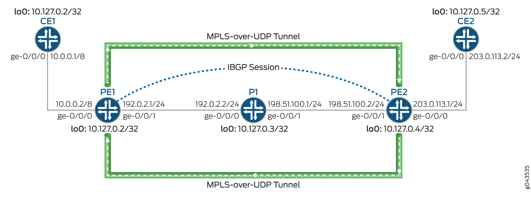
図 1 は、動的 MPLS-over-UDP トンネルを介したレイヤー 3 VPN のシナリオを示しています。カスタマーエッジ(CE)デバイスCE1およびCE2は、それぞれPE1およびPE2のプロバイダエッジ(PE)デバイスに接続します。PE デバイスはプロバイダ デバイス(デバイス P1)に接続され、内部 BGP(IBGP)セッションが 2 つの PE デバイスを相互接続します。動的ネクストホップベースの双方向 MPL-over-UDP トンネルが PE デバイス間に設定されています。
MPLS-over-UDP トンネルは次のように処理されます。
-
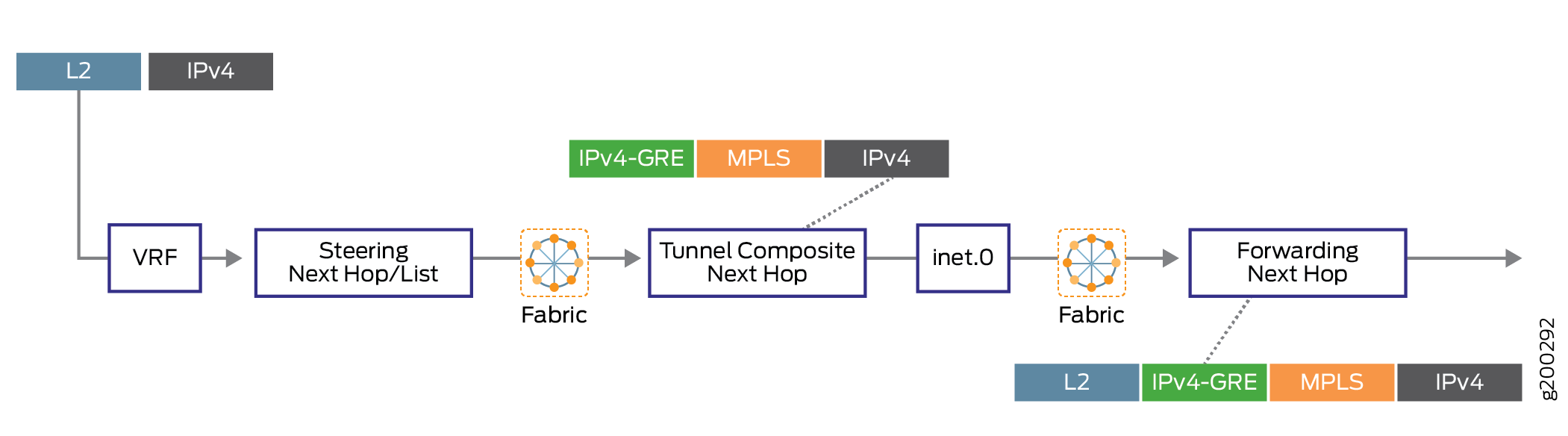
MPLS-over-UDP トンネルが設定された後、inet.3 ルーティング テーブルで、トンネル複合ネクストホップを持つトンネル宛先マスク ルートがトンネル用に作成されます。この IP トンネル ルートは、動的トンネル設定が削除される場合にのみ取り消されます。
トンネル複合ネクストホップ属性には、次のようなものがあります。
-
レイヤー3 VPN複合ネクストホップが無効の場合—送信元アドレスと宛先アドレス、カプセル化文字列、VPNラベル
-
レイヤー3 VPN複合ネクストホップとプレフィックス単位のVPNラベル割り当てが有効な場合—送信元アドレス、宛先アドレス、カプセル化文字列。
-
レイヤー3 VPN複合ネクストホップが有効で、プレフィックス単位のVPNラベル割り当てが無効になっている場合—送信元アドレス、宛先アドレス、およびカプセル化文字列。この場合のルートは、セカンダリルートを持つ他の仮想ルーティングおよび転送インスタンステーブルに追加されます。
-
-
PE デバイスは、IBGP セッションを使用して相互接続されます。リモート BGP ネイバーへの IBGP ルートネクストホップはプロトコルネクストホップであり、トンネルネクストホップとのトンネルマスクルートを使用して解決されます。
-
プロトコルネクストホップがトンネル複合ネクストホップ上で解決された後、転送ネクストホップを持つ間接ネクストホップが作成されます。
-
トンネル複合ネクストホップは、間接ネクストホップのネクストホップを転送するために使用されます。
設定
CLIクイック構成
この例を迅速に設定するには、以下のコマンドをコピーして、テキストファイルに貼り付け、改行を削除し、ネットワーク設定に一致させる必要がある詳細情報を変更し、コマンドを [edit] 階層レベルでCLIにコピーアンドペーストして、設定モードから commit を入力します。
CE1
set interfaces ge-0/0/0 unit 0 family inet address 10.0.0.1/8
set interfaces lo0 unit 0 family inet address 10.127.0.1/32
set routing-options router-id 10.127.0.1
set routing-options autonomous-system 65200
set protocols bgp group ce1-pe1 export export-loopback-direct
set protocols bgp group ce1-pe1 peer-as 100
set protocols bgp group ce1-pe1 neighbor 10.0.0.2
set policy-options policy-statement export-loopback-direct term term-1 from interface lo0.0
set policy-options policy-statement export-loopback-direct term term-1 from route-filter 10.127.0.1/32 exact
set policy-options policy-statement export-loopback-direct term term-1 then accept
CE2
set interfaces ge-0/0/0 unit 0 family inet address 203.0.113.2/24
set interfaces lo0 unit 0 family inet address 10.127.0.5/32
set routing-options router-id 10.127.0.5
set routing-options autonomous-system 65200
set protocols bgp group ce1-pe1 export export-loopback-direct
set protocols bgp group ce1-pe1 peer-as 65100
set protocols bgp group ce1-pe1 neighbor 203.0.113.1
set policy-options policy-statement export-loopback-direct term term-1 from interface lo0.0
set policy-options policy-statement export-loopback-direct term term-1 from route-filter 10.127.0.5/32 exact
set policy-options policy-statement export-loopback-direct term term-1 then accept
PE1
set interfaces ge-0/0/0 unit 0 family inet address 10.0.0.2/8
set interfaces ge-0/0/1 unit 0 family inet address 192.0.2.1/24
set interfaces ge-0/0/1 unit 0 family mpls
set interfaces lo0 unit 0 family inet address 10.127.0.2/32
set routing-options static route 10.33.0/16 next-hop 192.0.2.2
set routing-options router-id 10.127.0.2
set routing-options autonomous-system 65100
set routing-options forwarding-table export pplb
set routing-options dynamic-tunnels gre next-hop-based-tunnel
set routing-options dynamic-tunnels udp-dyn-tunnel-to-pe2 source-address 10.127.0.2
set routing-options dynamic-tunnels udp-dyn-tunnel-to-pe2 udp
set routing-options dynamic-tunnels udp-dyn-tunnel-to-pe2 destination-networks 10.127.0.0/24
set protocols bgp group IBGP type internal
set protocols bgp group IBGP local-address 10.127.0.2
set protocols bgp group IBGP family inet-vpn unicast
set protocols bgp group IBGP neighbor 10.127.0.4
set protocols ospf area 0.0.0.0 interface ge-0/0/1.0
set protocols ospf area 0.0.0.0 interface lo0.0 passive
set routing-instances MPLS-over-UDP-PE1 instance-type vrf
set routing-instances MPLS-over-UDP-PE1 interface ge-0/0/0.0
set routing-instances MPLS-over-UDP-PE1 route-distinguisher 10.127.0.2:1
set routing-instances MPLS-over-UDP-PE1 vrf-target target:600:1
set routing-instances MPLS-over-UDP-PE1 protocols bgp group pe1-ce1 peer-as 65200
set routing-instances MPLS-over-UDP-PE1 protocols bgp group pe1-ce1 neighbor 10.0.0.1 as-override
P1
set interfaces ge-0/0/0 unit 0 family inet address 192.0.2.2/24
set interfaces ge-0/0/0 unit 0 family mpls
set interfaces ge-0/0/1 unit 0 family inet address 198.51.100.1/24
set interfaces ge-0/0/1 unit 0 family mpls
set interfaces lo0 unit 0 family inet address 10.127.0.3/32
set routing-options router-id 10.127.0.3
set routing-options autonomous-system 65100
set protocols ospf area 0.0.0.0 interface ge-0/0/0.0
set protocols ospf area 0.0.0.0 interface ge-0/0/1.0
set protocols ospf area 0.0.0.0 interface lo0.0 passive
PE2
set interfaces ge-0/0/0 unit 0 family inet address 203.0.113.1/24
set interfaces ge-0/0/1 unit 0 family inet address 198.51.100.2/24
set interfaces ge-0/0/1 unit 0 family mpls
set interfaces lo0 unit 0 family inet address 10.127.0.4/8
set routing-options nonstop-routing
set routing-options router-id 10.127.0.4
set routing-options autonomous-system 65100
set routing-options forwarding-table export pplb
set routing-options dynamic-tunnels udp-dyn-tunnel-to-pe1 source-address 10.127.0.4
set routing-options dynamic-tunnels udp-dyn-tunnel-to-pe1 udp
set routing-options dynamic-tunnels udp-dyn-tunnel-to-pe1 destination-networks 10.127.0.0/24
set protocols bgp group IBGP type internal
set protocols bgp group IBGP local-address 10.127.0.4
set protocols bgp group IBGP family inet-vpn unicast
set protocols bgp group IBGP neighbor 10.127.0.2
set protocols ospf area 0.0.0.0 interface ge-0/0/1.0
set protocols ospf area 0.0.0.0 interface lo0.0 passive
set routing-instances MPLS-over-UDP-PE2 instance-type vrf
set routing-instances MPLS-over-UDP-PE2 interface ge-0/0/0.0
set routing-instances MPLS-over-UDP-PE2 route-distinguisher 10.127.0.4:1
set routing-instances MPLS-over-UDP-PE2 vrf-target target:600:1
set routing-instances MPLS-over-UDP-PE2 protocols bgp group ebgp peer-as 65200
set routing-instances MPLS-over-UDP-PE2 protocols bgp group ebgp neighbor 203.0.113.2 as-override
手順
ステップバイステップでの手順
次の例では、設定階層内のさまざまなレベルに移動する必要があります。CLI のナビゲーションについては、CLIユーザー・ガイド の コンフィギュレーション・モードでのCLIエディタの使用を参照してください。
デバイスPE1を設定するには:
-
デバイスのループバック インターフェイスを含むデバイス インターフェイスを設定します。
[edit interfaces]
user@PE1# set ge-0/0/0 unit 0 family inet address 10.0.0.2/8
user@PE1# set ge-0/0/1 unit 0 family inet address 192.0.2.1/24
user@PE1# set ge-0/0/1 unit 0 family mpls
user@PE1# set lo0 unit 0 family inet address 10.127.0.2/8
-
デバイス P1 をネクストホップ宛先とするデバイス PE1 からのルートのスタティック ルートを設定します。
[edit routing-options]
user@PE1# set static route 10.33.0.0/16 next-hop 192.0.2.2
-
機器 PE1 のルータ ID と自律システム番号を設定します。
[edit routing-options]
user@PE1# set router-id 10.127.0.2
user@PE1# set autonomous-system 65100
-
(PTXシリーズのみ)ポリシー制御を設定して、選択したプレフィックスを介した MPLS-over-UDP 動的トンネル ルートを解決します。
[edit routing-options dynamic-tunnels]
user@PTX-PE1# set forwarding-rib inet.0 inet-import dynamic-tunnel-fwd-route-import
-
(PTXシリーズのみ)を介した動的トンネル宛先ルートを解決するための inet-import ポリシーを設定します。
[edit policy-options]
user@PTX-PE1# set policy-statement dynamic-tunnel-fwd-route-import term 1 from route-filter 10.127.0.4/32 exact
user@PTX-PE1# set policy-statement dynamic-tunnel-fwd-route-import term 1 then accept
user@PTX-PE1# set policy-options policy-statement dynamic-tunnel-fwd-route-import then reject
-
PEデバイス間のIBGPピアリングを設定します。
[edit protocols]
user@PE1# set bgp group IBGP type internal
user@PE1# set bgp group IBGP local-address 10.127.0.2
user@PE1# set bgp group IBGP family inet-vpn unicast
user@PE1# set bgp group IBGP neighbor 10.127.0.4
-
管理インターフェイスを除くデバイス PE1 のすべてのインターフェイスで OSPF を設定します。
[edit protocols]
user@PE1# set ospf area 0.0.0.0 interface ge-0/0/1.0
user@PE1# set ospf area 0.0.0.0 interface lo0.0 passive
-
デバイス PE1 でネクストホップベースの動的 GRE トンネル設定を有効にします。
注:この手順は、ネクストホップベースの動的GREトンネルとMPLS-over-UDPトンネルの実装上の違いを説明するためにのみ必要です。
[edit routing-options]
user@PE1# set dynamic-tunnels gre next-hop-based-tunnel
-
デバイスPE1からデバイスPE2へのMPLS-over-UDPトンネルパラメータを設定します。
[edit routing-options]
user@PE1# set dynamic-tunnels udp-dyn-tunnel-to-pe2 source-address 10.127.0.2
user@PE1# set dynamic-tunnels udp-dyn-tunnel-to-pe2 udp
user@PE1# set dynamic-tunnels udp-dyn-tunnel-to-pe2 destination-networks 10.127.0.0/24
-
デバイス PE1 の VRF ルーティング インスタンスと、その他のルーティング インスタンス パラメーターを設定します。
[edit routing-instances]
user@PE1# set MPLS-over-UDP-PE1 instance-type vrf
user@PE1# set MPLS-over-UDP-PE1 interface ge-0/0/0.0
user@PE1# set MPLS-over-UDP-PE1 route-distinguisher 10.127.0.2:1
user@PE1# set MPLS-over-UDP-PE1 vrf-target target:600:1
-
デバイスCE1とのピアリングのルーティングインスタンス設定でBGPを有効にします。
[edit routing-instances]
user@PE1# set MPLS-over-UDP-PE1 protocols bgp group pe1-ce1 peer-as 65200
user@PE1# set MPLS-over-UDP-PE1 protocols bgp group pe1-ce1 neighbor 10.0.0.1 as-override
結果
設定モードから、show interfaces 、show routing-options、show protocols、およびshow routing-instances のコマンドを入力して設定を確認します。出力結果に意図した設定内容が表示されない場合は、この例の手順を繰り返して設定を修正します。
user@PE1# show interfaces
ge-0/0/0 {
    unit 0 {
        family inet {
            address 10.0.0.2/8;
        }
    }
}
ge-0/0/1 {
    unit 0 {
        family inet {
            address 192.0.2.1/24;
        }
        family mpls;
    }
}
lo0 {
    unit 0 {
        family inet {
            address 10.127.0.2/32;
        }
    }
}
user@PE1# show routing-options
static {
    route 10.33.0.0/16 next-hop 192.0.2.2;
}
router-id 10.127.0.2;
autonomous-system 65100;
forwarding-table {
    export pplb;
}
dynamic-tunnels {
    gre next-hop-based-tunnel;
    udp-dyn-tunnel-to-pe2 {
        source-address 10.127.0.2;
        udp;
        destination-networks {
            10.127.0.0/24;
        }
    }
}
user@PE1# show protocols
bgp {
    group IBGP {
        type internal;
        local-address 10.127.0.2;
        family inet-vpn {
            unicast;
        }
        neighbor 10.127.0.4;
    }
}
ospf {
    area 0.0.0.0 {
        interface ge-0/0/1.0;
        interface lo0.0 {
            passive;
        }
    }
}
user@PE1# show routing-instances
MPLS-over-UDP-PE1 {
    instance-type vrf;
    interface ge-0/0/0.0;
    route-distinguisher 10.127.0.2:1;
    vrf-target target:600:1;
    protocols {
        bgp {
            group pe1-ce1 {
                peer-as 65200;
                neighbor 10.0.0.1 {
                    as-override;
                }
            }
        }
    }
}
デバイスの設定が完了したら、設定モードから commit を入力します。
検証
設定が正常に機能していることを確認します。
PE デバイス間の接続の検証
目的
デバイス PE1 とデバイス PE2 間の BGP ピアリング ステータス、およびデバイス PE2 から受信した BGP ルートを確認します。
アクション
運用モードから、 show bgp summary コマンドを実行し、コマンド show route receive-protocol bgp ip-address table bgp.l3vpn.0 します。
user@PE1> show bgp summary
Groups: 2 Peers: 2 Down peers: 0
Table          Tot Paths  Act Paths Suppressed    History Damp State    Pending
bgp.l3vpn.0
                       2          2          0          0          0          0
Peer                     AS      InPkt     OutPkt    OutQ   Flaps Last Up/Dwn State|#Active/Received/Accepted/Damped...
10.127.0.4             65100        139        136       0       0       58:23 Establ
  bgp.l3vpn.0: 2/2/2/0
  MPLS-over-UDP-PE1.inet.0: 2/2/2/0
10.10.0.1               65200        135        136       0       0       58:53 Establ
MPLS-over-UDP-PE1.inet.0: 1/1/1/0user@PE1> show route receive-protocol bgp 10.127.0.4 table bgp.l3vpn.0 bgp.l3vpn.0: 2 destinations, 2 routes (2 active, 0 holddown, 0 hidden) Prefix Nexthop MED Lclpref AS path 10.127.0.4:1:127.0.0.5/8 * 10.127.0.4 65100 65200 I
意味
-
最初の出力では、BGP セッション状態は
Establであり、これはセッションが稼働中で、PE デバイスがピアリングされていることを意味します。 -
2番目の出力では、デバイスPE1がデバイスPE2から a BGPルート を学習しています。
デバイス PE1 での動的トンネル ルートの確認
目的
inet.3 ルーティングテーブル内のルートと、デバイス PE1 の動的トンネルデータベース情報を確認します。
アクション
動作モードから、 show route table inet.3、 show dynamic-tunnels database terse、 show dynamic-tunnels database、および show dynamic-tunnels database summary コマンドを実行します。
user@PE1> show route table inet.3
inet.3: 2 destinations, 2 routes (2 active, 0 holddown, 0 hidden)
+ = Active Route, - = Last Active, * = Both
10.127.0.0/24     *[Tunnel/300] 00:21:18
                      Tunnel
127.0.0.4/8     *[Tunnel/300] 00:21:18
Tunnel Compositeuser@PE1> show dynamic-tunnels database terse Table: inet.3 Destination-network: 10.127.0.0/24 Destination Source Next-hop Type Status 10.127.0.4/8 10.127.0.2 0xb395b10 nhid 613 udp Up
user@PE1> show dynamic-tunnels database
Table: inet.3
. . .
Tunnel to: 10.127.0.4/32
  Reference count: 2
  Next-hop type: UDP
    Source address: 10.127.0.2 Tunnel Id: 2
    Next hop: tunnel-composite, 0xb395b10, nhid 613
      VPN Label: Push 299776 Reference count: 3
      Traffic Statistics: Packets 0, Bytes 0
State: Upuser@PE1> show dynamic-tunnels database summary Dynamic Tunnels, Total 1 displayed GRE Tunnel: Active Tunnel Mode, Next Hop Base IFL Based, Total 0 displayed, Up 0, Down 0 Nexthop Based, Total 0 displayed, Up 0, Down 0 RSVP Tunnel: Total 0 displayed UDP Tunnel: Total 1 displayed, Up 1, Down 0
意味
-
最初の出力では、デバイス PE1 に MPLS-over-UDP トンネルが設定されているため、inet.3 ルーティング テーブルのルート エントリーに対してトンネル複合ルートが作成されます。
-
残りの出力では、MPLS-over-UDP トンネルが、トンネル カプセル化タイプ、トンネル ネクスト ホップ パラメータ、トンネル ステータスとともに表示されます。
デバイス PE2 での動的トンネル ルートの確認
目的
inet.3 ルーティング テーブル内のルートと、デバイス PE2 の動的トンネル データベース情報を確認します。
アクション
動作モードから、 show route table inet.3と show dynamic-tunnels database terse コマンドを実行します。
user@PE2> show route table inet.3
inet.3: 2 destinations, 2 routes (2 active, 0 holddown, 0 hidden)
+ = Active Route, - = Last Active, * = Both

10.127.0.0/24      *[Tunnel/300] 00:39:31
                      Tunnel
10.127.0.2/32     *[Tunnel/300] 00:24:53
Tunnel Compositeuser@PE1> show dynamic-tunnels database terse Table: inet.3 Destination-network: 127.0.0.0/8 Destination Source Next-hop Type Status 10.127.0.2/32 10.127.0.4 0xb395450 nhid 615 udp Up
意味
出力には、デバイス PE1 と同様に、MPLS-over-UDP トンネルの作成と、ネクストホップ インターフェイスとして割り当てられたネクストホップ ID が表示されます。
ルートに期待される間接ネクストホップフラグがあることを確認する
目的
デバイス PE1 とデバイス PE2 が、パケット転送エンジン転送テーブル上で、間接ネクストホップから転送ネクストホップ バインディングへの設定されていることを確認します。
アクション
動作モードから、デバイスPE1とデバイスPE2で show krt indirect-next-hop コマンドを実行します。
user@PE1> show krt indirect-next-hop
Indirect Nexthop:
Index: 1048574 Protocol next-hop address: 10.127.0.4
  RIB Table: bgp.l3vpn.0
  Label: Push 299776
  Policy Version: 1                     References: 1
  Locks: 3                              0xb2ab630
  Flags: 0x0
  INH Session ID: 0x0
  INH Version ID: 0
  Ref RIB Table: unknown
        Tunnel type: UDP, Reference count: 3, nhid: 613
        Destination address: 10.127.0.4, Source address: 10.127.0.2
        Tunnel id: 2, VPN Label: Push 299776, TTL action: prop-ttl
      IGP FRR Interesting proto count : 1
      Chain IGP FRR Node Num          : 1
         IGP Resolver node(hex)       : 0xb3c70dc
         IGP Route handle(hex)        : 0xb1ae688      IGP rt_entry protocol        : Tunnel
IGP Actual Route handle(hex) : 0x0 IGP Actual rt_entry protocol : Anyuser@PE2> show krt indirect-next-hop
Indirect Nexthop:
Index: 1048575 Protocol next-hop address: 10.127.0.2
RIB Table: bgp.l3vpn.0
Label: Push 299776
Policy Version: 1 References: 2
Locks: 3 0xb2ab740
Flags: 0x0
INH Session ID: 0x0
INH Version ID: 0
Ref RIB Table: unknown
Tunnel type: UDP, Reference count: 3, nhid: 615
Destination address: 10.127.0.2, Source address: 10.127.0.4
Tunnel id: 1, VPN Label: Push 299776, TTL action: prop-ttl
IGP FRR Interesting proto count : 2
Chain IGP FRR Node Num : 1
IGP Resolver node(hex) : 0xb3d3a28
IGP Route handle(hex) : 0xb1ae634 IGP rt_entry protocol : Tunnel
IGP Actual Route handle(hex) : 0x0 IGP Actual rt_entry protocol : Any意味
この出力は、ネクストホップベースの動的 MPLS-over-UDP トンネルが PE デバイス間に作成されたことを示しています。
トラブルシューティング
ネクストホップベースの動的トンネルのトラブルシューティングを行うには、以下を参照してください。
コマンドのトラブルシューティング
問題点
ネクストホップベースの動的 MPLS-over-UDP トンネル設定は有効になりません。
ソリューション
ネクストホップベースの MPLS-over-UDP トンネル設定をトラブルシューティングするには、[edit routing-options dynamic-tunnels] ステートメント階層で以下の traceroute コマンドを使用します。
-
traceoptions file file-name -
traceoptions file size file-size -
traceoptions flag all
以下はその一例です。
[edit routing-options dynamic-tunnels]
traceoptions {
    file udp_dyn_pe1.wri size 4294967295;
    flag all;
}
ネクストホップベースの動的トンネルのアンチスプーフィング保護の概要
データセンターへの大規模なIPトンネルの導入の増加に伴い、侵害された仮想マシン(VM)からの悪意のあるトラフィックをユーザーが制限できるセキュリティ対策を追加する必要があります。考えられる攻撃の1つは、ゲートウェイルーターを介して侵害されたサーバーから任意の顧客VPNにトラフィックを挿入することです。このような場合、IPトンネルのスプーフィング対策チェックにより、正当な送信元のみが指定されたIPトンネルからデータセンターにトラフィックを注入していることが確認されます。
ネクストホップベースの動的 IP トンネルは、デバイス上に作成されたすべての動的トンネルに対して、トンネル複合ネクストホップを作成します。ネクストホップベースの動的トンネルでは、新たに動的トンネルを設定するたびに物理インターフェイスに依存しなくなるため、ネクストホップベースの動的トンネルを設定すると、デバイスに作成できる動的トンネルの数に比べて拡張上のメリットが得られます。Junos OS Release 17.1 以降、ネクストホップベースの動的 IP トンネルのなりすまし対策機能が、ネクストホップベースの動的トンネルに提供されます。この機能拡張により、セキュリティ対策が実装され、ゲートウェイルーターを介して侵害されたサーバーから任意の顧客VPNにトラフィックが挿入されるのを防ぎます。
アンチスプーフィングは、パケット転送エンジンのリバースパス転送チェックを使用して実装されます。チェックは、トンネルを通ってルーティングインスタンスに到達するトラフィックに対して実装されます。現在、ゲートウェイルーターがトンネルからトラフィックを受信すると、宛先検索のみが行われ、それに応じてパケットが転送されます。なりすまし対策保護が有効になっている場合、ゲートウェイ ルーターは、トンネル宛先の検索に加えて、VPN 内のカプセル化パケット IP ヘッダーの送信元アドレス検索も実行します。これにより、正規の送信元が、指定された IP トンネルを介してトラフィックを注入していることを確認できます。その結果、なりすまし防止保護により、トンネル トラフィックが指定されたトンネル上の正当な送信元から受信されることが保証されます。
図 2 は、スプーフィング防止保護の要件を含むサンプル トポロジを示しています。
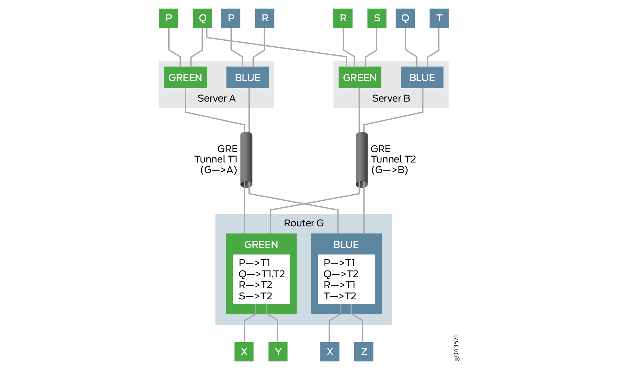
この例では、ゲートウェイルーターはルーターGです。ルーターGには緑と青の2つのVPNがあります。サーバー A とサーバー B の 2 つのサーバーは、それぞれネクストホップベースの動的トンネル T1 および T2 を介して、ルーター G の Green VPN と Blue VPN に到達できます。サーバーに接続された複数のホストと仮想マシン(P、Q、R、S、T)は、ゲートウェイルーターであるルーターGを介してVPNに到達できます。ルーターGには、グリーンVPNとブルーVPNのVRF(仮想ルーティングと転送)テーブルがあり、それぞれにこれらのVPN内の仮想マシンの到達可能性情報が入力されています。
たとえば、VPN Green では、ルーター G はトンネル T1 を使用してホスト P に到達し、トンネル T2 を使用してホスト R および S に到達し、トンネル T1 と T2 の間でロード バランシングを実行してマルチホーム ホスト Q に到達します。VPN Blueでは、ルーターGはトンネルT1を使用してホストPおよびRに到達し、トンネルT2を使用してホストQおよびTに到達します。
以下の場合、リバースパスフォワーディングのチェックに合格します。
パケットは、指定されたトンネル上の正当な送信元から送信されます。
VPN Green のホスト P は、トンネル T1 を使用してホスト X にパケットを送信します。ルーター G はトンネル T1 を通じてホスト P に到達できるため、パケットの通過を許可し、パケットをホスト X に転送します。
パケットは、指定されたトンネル上のマルチホーム送信元から送信されます。
VPN Green のホスト Q は、サーバー A および B 上でマルチホーム化されており、トンネル T1 および T2 を介してルーター G に到達できます。ホスト Q は、トンネル T1 を使用してホスト Y にパケットを送信し、トンネル T2 を使用してホスト X にパケットを送信します。ルーター G はトンネル T1 および T2 を介してホスト Q に到達できるため、パケットの通過を許可し、それぞれホスト Y および X に転送します。
レイヤー3 VPNでは、デフォルトでなりすまし対策が有効になっていません。ネクストホップベースの動的トンネルのアンチスプーフィングを有効にするには、[edit routing-instances routing-instance-name routing-options forwarding-table]階層レベルで ip-tunnel-rpf-checkステートメントを含めます。リバースパス転送チェックは、VRFルーティングインスタンスにのみ適用されます。デフォルト モードは strict に設定されており、非指定トンネル上の送信元からのパケットはチェックに合格しません。ip-tunnel-rpf-checkモードは、パケットが存在しない送信元から送信された場合、リバースパス転送チェックが失敗するlooseに設定することができます。オプションのファイアウォールフィルターを ip-tunnel-rpf-check ステートメントの下に設定して、リバースパス転送チェックに失敗したパケットをカウントして記録することができます。
次のサンプル出力は、スプーフィング対策の構成を示しています。
[edit routing-instances routing-instance-name routing-options forwarding-table]
ip-tunnel-rpf-check {
    mode loose;
    fail-filter filter-name;
}
ネクストホップベースの動的トンネルのなりすまし防止を構成する場合は、以下のガイドラインを考慮してください。
スプーフィング対策保護は、IPv4 トンネルと IPv4 データ トラフィックに対してのみ有効にできます。なりすまし対策機能は、IPv6 トンネルおよび IPv6 データ トラフィックではサポートされていません。
ネクストホップベースの動的トンネルのスプーフィング対策では、侵害された仮想マシンを検出して防止できますが(内部ソースのリバースパス転送チェック)、ラベルスプーフィングを行っている侵害されたサーバーは検出できません。
ネクストホップベースのIPトンネルは、inet.0ルーティングテーブルで開始および終了できます。
なりすまし防止は、VRFルーティングインスタンスにラベルスイッチインターフェイス(LSI)(
vrf-table-labelを使用)または仮想トンネル(VT)インターフェイスがある場合に有効です。VRFルーティングインスタンスにラベルper-next-hopと、なりすまし防止はサポートされていません。rpf fail-filterは、内部 IP パケットにのみ適用されます。アンチスプーフィングチェックを有効にしても、デバイス上のネクストホップベースの動的トンネルのスケーリング制限には影響しません。
VRF ルーティング インスタンスに対してスプーフィング対策保護を有効にした場合のシステム リソース使用率は、スプーフィング対策が有効になっていない場合のネクストホップベースの動的トンネルの使用率よりもわずかに高くなります。
スプーフィング対策保護には、追加の送信元 IP アドレス チェックが必要であり、ネットワーク パフォーマンスへの影響は最小限です。
なりすまし対策では、GRES(グレースフル ルーティング エンジン スイッチオーバー)と ISSU(インサービス ソフトウェア アップグレード)がサポートされています。
例:ネクストホップベースの動的トンネルのアンチスプーフィング保護の設定
この例では、仮想ルーティングおよび転送(VRF)ルーティング インスタンスのリバース パス フォワーディング チェックを設定し、ネクストホップベースの動的トンネルのアンチスプーフィング保護を有効にする方法を示します。このチェックでは、正規の送信元が、指定された IP トンネルを介してトラフィックを注入していることを確認します。
要件
この例では、以下のハードウェアとソフトウェアのコンポーネントを使用しています。
MICを備えた3台のMXシリーズルーター、それぞれがホストデバイスに接続されています。
1 つまたはすべてのルーターで実行されている Junos OS リリース 17.1 以降。
始める前に:
フレキシブルPICコンセントレータでトンネルサービスの設定を有効にします。
ルーター・インターフェイスを設定します。
ルーター ID を設定し、ルーターの自律システム番号を割り当てます。
トンネルエンドポイントとの内部BGP(IBGP)セッションを確立します。
すべてのルーターで RSVP を設定します。
すべてのルーターでOSPF またはその他の内部ゲートウェイ プロトコルを設定します。
2つのルーター間に2つの動的ネクストホップベースのIPトンネルを設定します。
ルーター/ホスト間接続ごとに VRF ルーティング インスタンスを設定します。
概要
Junos OS リリース 17.1 以降、ネクストホップベースの動的 IP トンネルにスプーフィング対策機能が追加され、パケット転送エンジンのリバースパスフォワーディングを使用して、トンネルを経由してルーティングインスタンスに到達するトラフィックのチェックが実装されます。
現在、ゲートウェイ ルーターがトンネルからトラフィックを受信すると、宛先アドレスの検索のみが実行されてから転送されます。なりすまし防止保護により、ゲートウェイ ルーターは VPN 内のカプセル化パケット IP ヘッダーの送信元アドレス検索を行い、正当な送信元が指定された IP トンネルを介してトラフィックを注入していることを確認します。これは厳密モードと呼ばれ、スプーフィング対策保護の既定の動作です。非指定トンネルからのトラフィックを転送させるには、損失モードでリバース パス フォワーディング チェックを有効にします。存在しない送信元から受信したトラフィックの場合、strict モードと loose モードの両方でリバース パス転送チェックが失敗します。
アンチスプーフィングは、VRF ルーティングインスタンスでサポートされています。動的トンネルのアンチスプーフィングを有効にするには、[edit routing-instances routing-instance-name routing-options forwarding-table]階層レベルで ip-tunnel-rpf-check ステートメントを含めます。
トポロジー
図 3 は、なりすまし防止保護が有効なサンプル ネットワーク トポロジを示しています。ルーター R0、R1、および R2 は、それぞれホスト Host0、Host1、および Host2 に接続されています。2つの汎用ルーティングカプセル化(GRE)ネクストホップベースの動的トンネル、トンネル1およびトンネル2 – それぞれルーターR0をルーターR1およびR2に接続します。VRFルーティングインスタンスは、各ルーターとそれに接続されたホストデバイスの間で実行されています。
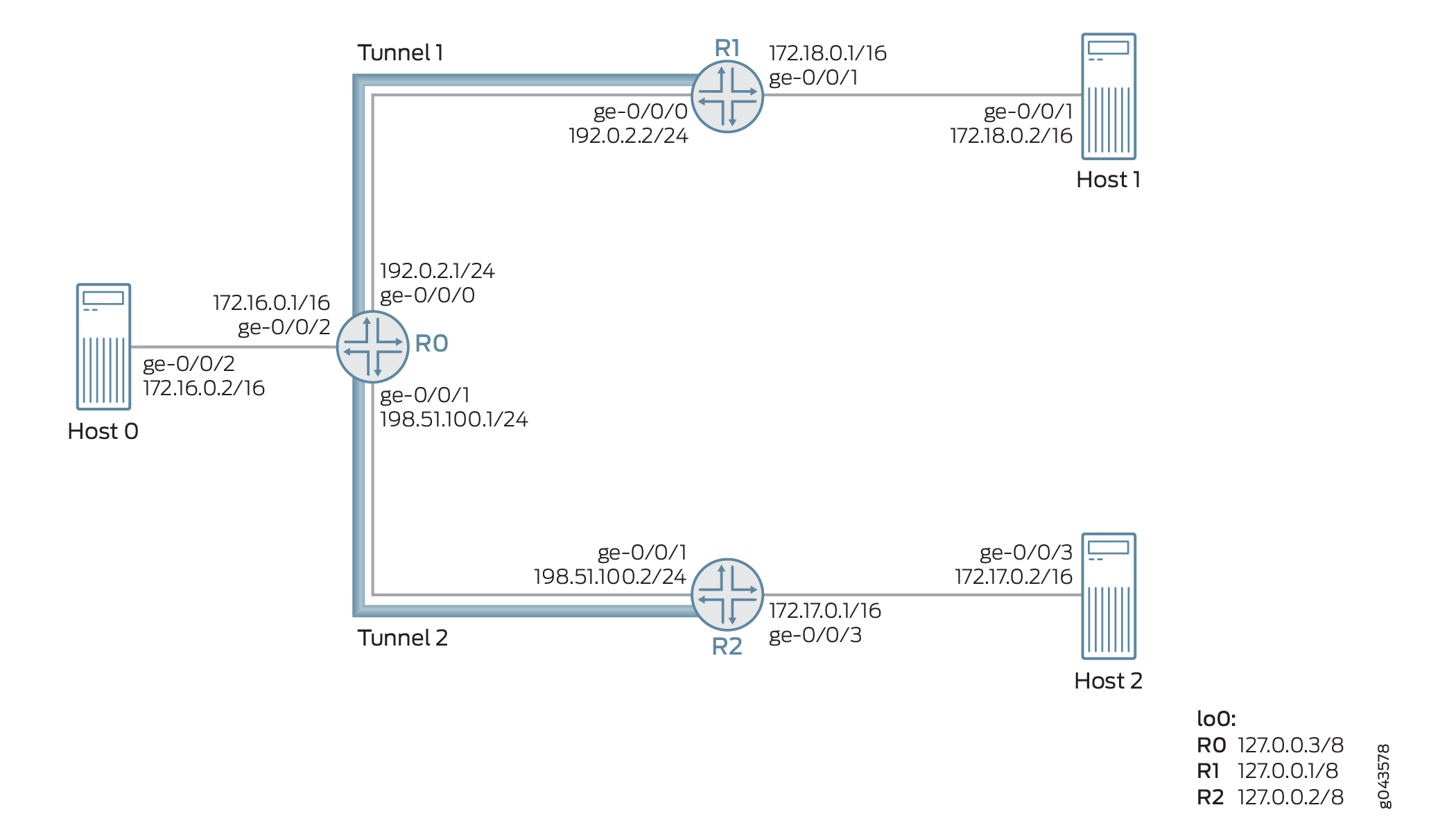
例として、3 つのパケット(パケット A、B、C)が、ネクストホップベースの動的 GRE トンネル(トンネル 2)を介してルーター R2 からルーター 0 で受信されます。これらのパケットの送信元 IP アドレスは、172.17.0.2 (パケット A)、172.18.0.2 (パケット B)、および 172.20.0.2 (パケット C) です。
パケットAとパケットBの送信元IPアドレスは、それぞれホスト2とホスト1に属しています。パケット C は存在しない送信元トンネルです。この例の指定トンネルはトンネル2で、非指定トンネルはトンネル1です。したがって、パケットは次のように処理されます。
Packet A- 送信元が指定されたトンネル(トンネル 2)から来ているため、パケット A はリバース パス転送チェックに合格し、トンネル 2 を通過する転送が処理されます。
Packet B- 送信元が非宛先トンネルであるトンネル1から来ているため、デフォルトでは、パケットBは厳密モードでリバースパス転送チェックに失敗します。ルーズ モードが有効になっている場合、パケット B は転送が許可されます。
Packet C- 送信元が存在しないトンネル送信元であるため、パケット C はリバース パス転送チェックに失敗し、パケットは転送されません。
設定
CLIクイック構成
この例を迅速に設定するには、以下のコマンドをコピーして、テキストファイルに貼り付け、改行を削除し、ネットワーク設定に一致させる必要がある詳細情報を変更し、コマンドを [edit] 階層レベルでCLIにコピーアンドペーストして、設定モードから commit を入力します。
ルーターR0
set interfaces ge-0/0/0 unit 0 family inet address 192.0.2.1/24
set interfaces ge-0/0/1 unit 0 family inet address 198.51.100.1/24
set interfaces ge-0/0/2 vlan-tagging
set interfaces ge-0/0/2 unit 0 vlan-id 1
set interfaces ge-0/0/2 unit 0 family inet address 172.16.0.1/16
set interfaces lo0 unit 0 family inet address 10.1.1.1/32
set routing-options router-id 10.1.1.1
set routing-options autonomous-system 100
set routing-options dynamic-tunnels gre next-hop-based-tunnel
set routing-options dynamic-tunnels T1 source-address 192.0.2.1
set routing-options dynamic-tunnels T1 gre
set routing-options dynamic-tunnels T1 destination-networks 192.0.2.0/24
set routing-options dynamic-tunnels T2 source-address 198.51.100.1
set routing-options dynamic-tunnels T2 gre
set routing-options dynamic-tunnels T2 destination-networks 198.51.100.0/24
set protocols rsvp interface all
set protocols rsvp interface fxp0.0 disable
set protocols bgp group IBGP type internal
set protocols bgp group IBGP local-address 10.1.1.1
set protocols bgp group IBGP family inet-vpn unicast
set protocols bgp group IBGP neighbor 20.1.1.1
set protocols bgp group IBGP neighbor 30.1.1.1
set protocols ospf traffic-engineering
set protocols ospf area 0.0.0.0 interface lo0.0 passive
set protocols ospf area 0.0.0.0 interface all
set routing-instances VPN1 instance-type vrf
set routing-instances VPN1 interface ge-0/0/2.0
set routing-instances VPN1 route-distinguisher 100:100
set routing-instances VPN1 vrf-target target:100:1
set routing-instances VPN1 vrf-table-label
set routing-instances VPN1 routing-options forwarding-table ip-tunnel-rpf-check mode strict
set routing-instances VPN1 protocols bgp group External type external
set routing-instances VPN1 protocols bgp group External family inet unicast
set routing-instances VPN1 protocols bgp group External peer-as 200
set routing-instances VPN1 protocols bgp group External neighbor 172.16.0.1
ルーター R1
set interfaces ge-0/0/0 unit 0 family inet address 192.0.2.2/24
set interfaces ge-0/0/1 vlan-tagging
set interfaces ge-0/0/1 unit 0 vlan-id 2
set interfaces ge-0/0/1 unit 0 family inet address 172.18.0.1/16
set interfaces lo0 unit 0 family inet address 20.1.1.1/32
set routing-options router-id 20.1.1.1
set routing-options autonomous-system 100
set routing-options dynamic-tunnels gre next-hop-based-tunnel
set routing-options dynamic-tunnels T1 source-address 192.0.2.2
set routing-options dynamic-tunnels T1 gre
set routing-options dynamic-tunnels T1 destination-networks 192.0.2.0/24
set protocols rsvp interface all
set protocols rsvp interface fxp0.0 disable
set protocols bgp group IBGP type internal
set protocols bgp group IBGP local-address 20.1.1.1
set protocols bgp group IBGP family inet-vpn unicast
set protocols bgp group IBGP neighbor 30.1.1.1
set protocols bgp group IBGP neighbor 10.1.1.1
set protocols ospf traffic-engineering
set protocols ospf area 0.0.0.0 interface lo0.0 passive
set protocols ospf area 0.0.0.0 interface all
set routing-instances VPN2 instance-type vrf
set routing-instances VPN2 interface ge-0/0/1.0
set routing-instances VPN2 route-distinguisher 100:200
set routing-instances VPN2 vrf-target target:200:1
set routing-instances VPN2 vrf-table-label
R2
set interfaces ge-0/0/1 unit 0 family inet address 198.51.100.2/24
set interfaces ge-0/0/2 vlan-tagging
set interfaces ge-0/0/2 unit 0 vlan-id 3
set interfaces ge-0/0/2 unit 0 family inet address 172.17.0.1/16
set interfaces lo0 unit 0 family inet address 30.1.1.1/32
set routing-options router-id 30.1.1.1
set routing-options autonomous-system 100
set routing-options dynamic-tunnels gre next-hop-based-tunnel
set routing-options dynamic-tunnels T2 source-address 198.51.100.2
set routing-options dynamic-tunnels T2 gre
set routing-options dynamic-tunnels T2 destination-networks 198.51.100.0/24
set protocols rsvp interface all
set protocols rsvp interface fxp0.0 disable
set protocols bgp group IBGP type internal
set protocols bgp group IBGP local-address 30.1.1.1
set protocols bgp group IBGP family inet-vpn unicast
set protocols bgp group IBGP neighbor 20.1.1.1
set protocols bgp group IBGP neighbor 10.1.1.1
set protocols ospf traffic-engineering
set protocols ospf area 0.0.0.0 interface lo0.0 passive
set protocols ospf area 0.0.0.0 interface all
set routing-instances VPN3 instance-type vrf
set routing-instances VPN3 interface ge-0/0/2.0
set routing-instances VPN3 route-distinguisher 100:300
set routing-instances VPN3 vrf-target target:300:1
set routing-instances VPN3 vrf-table-label
手順
ステップバイステップでの手順
次の例では、設定階層内のさまざまなレベルに移動する必要があります。CLI のナビゲーションについては、CLIユーザー・ガイド の コンフィギュレーション・モードでのCLIエディタの使用を参照してください。
ルーターR0を設定する。
ループバック インターフェイスを含め、ルーター R0 のインターフェイスを設定します。
[edit interfaces]
user@R0# set ge-0/0/0 unit 0 family inet address 192.0.2.1/24
user@R0# set ge-0/0/1 unit 0 family inet address 198.51.100.1/24
user@R0# set ge-0/0/2 vlan-tagging
user@R0# set ge-0/0/2 unit 0 vlan-id 1
user@R0# set ge-0/0/2 unit 0 family inet address 172.16.0.1/16
user@R0# set lo0 unit 0 family inet address 10.1.1.1/32
ルーター R0 のルーター ID と自律システム番号を割り当てます。
[edit routing-options]
user@R0# set router-id 10.1.1.1
user@R0# set autonomous-system 100
ルーター間のIBGPピアリングを設定します。
[edit protocols]
user@R0# set bgp group IBGP type internal
user@R0# set bgp group IBGP local-address 10.1.1.1
user@R0# set bgp group IBGP family inet-vpn unicast
user@R0# set bgp group IBGP neighbor 20.1.1.1
user@R0# set bgp group IBGP neighbor 30.1.1.1
管理インターフェイスを除くルーターR0のすべてのインターフェイスでOSPFを設定します。
[edit protocols]
user@R0# set ospf traffic-engineering
user@R0# set ospf area 0.0.0.0 interface lo0.0 passive
user@R0# set ospf area 0.0.0.0 interface all
管理インターフェイスを除くルーター R0 のすべてのインターフェイスで RSVP を設定します。
[edit protocols]
user@R0# set rsvp interface all
user@R0# set rsvp interface fxp0.0 disable
ルーター R0 でネクストホップベースの動的 GRE トンネル設定を有効にします。
[edit routing-options]
user@R0# set dynamic-tunnels gre next-hop-based-tunnel
ルーター R0 からルーター R1 への動的 GRE トンネル パラメーターを設定します。
[edit routing-options]
user@R0# set dynamic-tunnels T1 source-address 192.0.2.1
user@R0# set dynamic-tunnels T1 gre
user@R0# set dynamic-tunnels T1 destination-networks 192.0.2.0/24
ルーター R0 からルーター R2 への動的 GRE トンネル パラメーターを設定します。
[edit routing-options]
user@R0# set dynamic-tunnels T2 source-address 198.51.100.1
user@R0# set dynamic-tunnels T2 gre
user@R0# set dynamic-tunnels T2 destination-networks 198.51.100.0/24
ルーター R0 で仮想ルーティングおよび転送(VRF)ルーティング インスタンスを設定し、ホスト 1 に接続するインターフェイスを VRF インスタンスに割り当てます。
[edit routing-instances]
user@R0# set VPN1 instance-type vrf
user@R0# set VPN1 route-distinguisher 100:100
user@R0# set VPN1 vrf-target target:100:1
user@R0# set VPN1 vrf-table-label
user@R0# set VPN1 interface ge-0/0/2.0
VRFルーティングインスタンス用にホスト1との外部BGPセッションを設定します。
[edit routing-instances]
user@R0# set VPN1 protocols bgp group External type external
user@R0# set VPN1 protocols bgp group External family inet unicast
user@R0# set VPN1 protocols bgp group External peer-as 200
user@R0# set VPN1 protocols bgp group External neighbor 172.16.0.1
ルーター R0 の VRF ルーティング インスタンスのなりすまし防止を設定します。これにより、ルーター0でネクストホップベースの動的トンネルT1とT2のリバースパスフォワーディングチェックが有効になります。
[edit routing-instances]
user@R0# set VPN1 routing-options forwarding-table ip-tunnel-rpf-check mode strict
結果
設定モードから、show interfaces 、show routing-options、show protocols、およびshow routing-options のコマンドを入力して設定を確認します。出力結果に意図した設定内容が表示されない場合は、この例の手順を繰り返して設定を修正します。
user@R0# show interfaces
ge-0/0/0 {
    unit 0 {
        family inet {
            address 192.0.2.1/24;
        }
    }
}
ge-0/0/1 {
    unit 0 {
        family inet {
            address 198.51.100.1/24;
        }
    }
}
ge-0/0/2 {
    vlan-tagging;
    unit 0 {
        vlan-id 1;
        family inet {
            address 172.16.0.1/16;
        }
    }
}
lo0 {
    unit 0 {
        family inet {
            address 10.1.1.1/32;
        }
    }
}
user@R0# show routing-options
router-id 10.1.1.1;
autonomous-system 100;
dynamic-tunnels {
    gre next-hop-based-tunnel;
    T1 {
        source-address 192.0.2.1;
        gre;
        destination-networks {
            192.0.2.0/24;
        }
    }
    T2 {
        source-address 198.51.100.1;
        gre;
        destination-networks {
            198.51.100.0/24;
        }
    }
}
user@R0# show protocols
rsvp {
    interface all;
    interface fxp0.0 {
        disable;
    }
}
bgp {
    group IBGP {
        type internal;
        local-address 10.1.1.1;
        family inet-vpn {
            unicast;
        }
        neighbor 20.1.1.1;
        neighbor 30.1.1.1;
    }
}
ospf {
    traffic-engineering;
    area 0.0.0.0 {
        interface lo0.0 {
            passive;
        }
        interface all;
    }
}
user@R0# show routing-instances
VPN1 {
    instance-type vrf;
    interface ge-0/0/2.0;
    route-distinguisher 100:100;
    vrf-target target:100:1;
    vrf-table-label;
    routing-options {
        forwarding-table {
            ip-tunnel-rpf-check {
                mode strict;
            }
        }
    }
    protocols {
        bgp {
            group External {
                type external;
                family inet {
                    unicast;
                }
                peer-as 200;
                neighbor 172.16.0.1;
            }
        }
    }
}
検証
設定が正常に機能していることを確認します。
基本設定の確認
目的
ルーター R0 とルーター R1 および R2 の間の OSPF および BGP ピアリング ステータスを確認します。
アクション
運用モードから、 show ospf neighbor と show bgp summaryコマンドを実行します。
user@R0> show ospf neighbor
Address          Interface              State     ID               Pri  Dead
192.0.2.2        ge-0/0/0.0             Full      20.1.1.1         128    32
198.51.100.2     ge-0/0/1.0             Full      30.1.1.1         128    32

user@R0> show bgp summary
Groups: 2 Peers: 3 Down peers: 1
Table          Tot Paths  Act Paths Suppressed    History Damp State    Pending
bgp.l3vpn.0
                       0          0          0          0          0          0
Peer                     AS      InPkt     OutPkt    OutQ   Flaps Last Up/Dwn State|#Active/Received/Accepted/Damped...
20.1.1.1                100        182        178       0       0     1:20:27 Establ
  bgp.l3vpn.0: 0/0/0/0
30.1.1.1                100        230        225       0       0     1:41:51 Establ
  bgp.l3vpn.0: 0/0/0/0
172.16.0.1              200          0          0       0       0     1:42:08 Establ
意味
OSPF と BGP のセッションは、ルーター R0、R1、および R2 の間で稼働しています。
動的トンネル設定の確認
目的
ルーター R0 とルーター R1 および R2 の間にあるネクストホップベースの動的 GRE トンネルのステータスを確認します。
アクション
動作モードから、 show route table inet.3と show dynamic-tunnels database terse コマンドを実行します。
user@R0> show route table inet.3

inet.3: 2 destinations, 2 routes (2 active, 0 holddown, 0 hidden)
+ = Active Route, - = Last Active, * = Both

192.0.2.0/24       *[Tunnel/300] 01:47:57
                      Tunnel
192.0.2.2/24       *[Tunnel/300] 01:47:57
                      Tunnel Composite

198.51.100.0/24    *[Tunnel/300] 01:47:57
                      Tunnel
198.51.100.2/24    *[Tunnel/300] 01:47:57
Tunnel Compositeuser@R0> show dynamic-tunnels database terse Table: inet.3 Destination-network: 192.0.2.0/24 Destination Source Next-hop Type Status 192.0.2.2/24 192.0.2.1 0xb395e70 nhid 612 gre Up Destination-network: 198.51.100.0/24 Destination Source Next-hop Type Status 198.51.100.2 198.51.100.1 0xb395e70 nhid 612 gre Up
意味
2つのネクストホップベースの動的GREトンネル、トンネル1とトンネル2が立ち上がっています。
スプーフィング対策保護の設定の確認
目的
リバース パス フォワーディング チェックがルーター R0 の VRF ルーティング インスタンスで有効になっていることを確認します。
アクション
動作モードから、 show krt table VPN1.inet.0 detailを実行します。
user@R0> show krt table VPN1.inet.0 detail
KRT tables:
VPN1.inet.0                   : GF: 1 krt-index: 8     ID: 0 kernel-id: 8
        flags: (null)
        tunnel rpf config data : enable, strict, filter [0], 0x2
        tunnel rpf tlv data : enable, strict, filter [0], 0x4
        unicast reverse path: disabled
        fast-reroute-priority: 0
        Permanent NextHops
          Multicast        : 0 Broadcast : 0
          Receive          : 0   Discard   : 0
          Multicast Discard: 0   Reject    : 0
          Local            : 0   Deny      : 0
          Table            : 0
意味
設定されたリバースパス転送チェックは、厳密モードのVRFルーティングインスタンスで有効です。
ネクストホップベースの動的トンネルローカリゼーションの概要
ネクストホップベースの動的トンネルには、GRE(Generic Routing Encapsulation)トンネルと MPLS-over-UDP トンネルがあります。これらのトンネルは、インターフェイスベースのトンネルに比べて拡張上の利点があります。ただし、インターフェイスベースのトンネルとは異なり、ネクストホップベースの動的トンネルは本質的にアンカーレスであり、トンネルの転送情報がデバイス上のすべてのラインカードのパケット転送エンジン(PFE)に配信されます。これにより、デバイスでサポートされるトンネルの最大数が、1 つのラインカードのトンネル容量に制限されます。ローカリゼーションのサポートにより、ネクストホップベースの動的トンネルローカリゼーションを設定し、アンカーPFEとして指定されたラインカードのPFEでのみ転送情報を作成できます。デバイス上の他のラインカードのPFEには、パケットをアンカーPFEに誘導するための状態転送情報があります。これにより、デバイスでサポートされるトンネルの最大数を増やすことにより、拡張上の利点が得られます。
- ネクストホップベースの動的トンネルローカリゼーションのメリット
- ネクストホップベースの動的トンネルローカリゼーションの使用例
- ネクストホップベースの動的トンネルのローカライズによるトラフィック処理
- ネクストホップベースの動的トンネルローカリゼーションの設定
- ローカライズされたネクストホップベースの動的トンネルのトラブルシューティング
- ネクストホップベースの動的トンネルローカリゼーションでサポートされていない機能
ネクストホップベースの動的トンネルローカリゼーションのメリット
デバイスでサポートされるトンネルの最大数を増やすことにより、拡張上の利点を提供します。
ネクストホップベースの動的トンネルローカリゼーションの使用例
多数のMS-MPCをホストするIPsecゲートウェイデバイスは、IPSecトンネルの終端に使用され、中程度の負荷をサポートする必要があります。このサポートは、デバイスの拡張限界に達した場合に、ネクストホップベースの動的トンネルを使用することで影響を受けます。ネクストホップベースの動的トンネルのローカライズにより、サポートされるトンネルの最大数が増加し、デバイスは追加のファブリックホップを犠牲にして、より多くのトンネルを収容できます。
仮想パブリッククラウドデータセンターなどのインターネットまたはVPNゲートウェイデバイスの場合、ゲートウェイデバイスは多数のサーバーと通信する必要があります。データセンターサーバーには、ネクストホップベースの動的トンネルを介してアクセスできます。動的トンネルのアンカーレスプロパティは、デバイスの全体的なスケーリング数を制限します。ゲートウェイデバイスは、トラフィック需要の増加に伴い、複数のMPCをホストしています。ネクストホップベースの動的トンネルのローカライズにより、トンネルをMPC全体に分散できるため、トンネルスケーリング数を増やすことができます。
ネクストホップベースの動的トンネルのローカライズによるトラフィック処理
ローカリゼーションのサポートにより、ネクストホップベースの動的トンネル状態はアンカーのパケット転送エンジンに限定され、もう一方のパケット転送エンジンはトンネルアンカーにトラフィックを誘導するトンネルの状態を持ちます。
図 4 は、ローカライズなしのネクストホップベースの動的トンネルの転送パスを示しています。
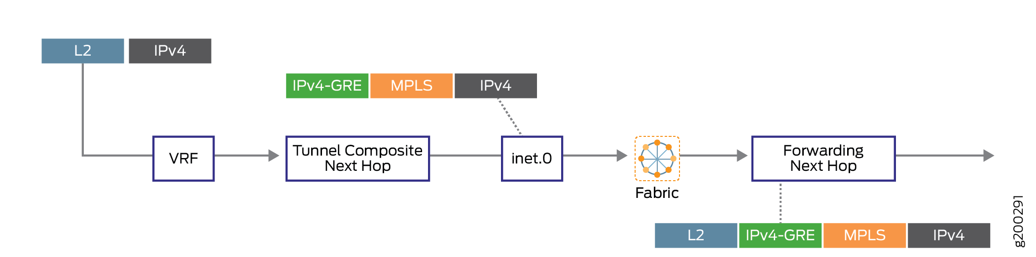
図 5 は、ローカライズを使用したネクストホップベースの動的トンネルの転送パスを示しています。
ネクストホップベースの動的トンネルローカリゼーションの設定
ローカリゼーションサポートは、新しく作成されたネクストホップベースの動的トンネル、または既存の非ローカル動的トンネルに対して設定できます。
新しいネクストホップベースの動的トンネルのローカリゼーションの設定
ネクストホップベースの動的トンネルのローカライズでは、ポリシーベースのアプローチを使用してプレフィックスグループを指定します。つまり、ルートポリシーは、ネクストホップベースの動的トンネルにローカリゼーションプロパティを適用するために使用されます。動的トンネル属性プロファイルは、 ポリシーを使用してプレフィックス グループに関連付けるためのルーティング オプションで作成および設定されます。
動的トンネル プロファイルの作成
動的トンネル プロファイルは、トンネル タイプとアンカー パケット転送エンジン情報を指定します。動的トンネルをローカライズするために、複数の動的トンネル プロファイルを作成できます。動的トンネル タイプの値は、GRE、UDP、または BGP-SIGNAL です。
BGP-SIGNALは有効なトンネルタイプではありませんが、BGP-SIGNALをトンネルタイプとして割り当てることで、BGP-signalled属性から作成されたトンネルがローカライズされます。BGP-SIGNALを使用する場合、トンネルタイプはBGPがTLVでアドバタイズするタイプに基づいて決定されます。BGP-SIGNALトンネルは、常にネクストホップベースのトンネルです。BGP-SIGNAL によって動的に作成される GRE トンネルは、ユーザーが GRE によって作成されたトンネルを IFL を使用するように手動で設定している場合でも、常にネクストホップベースです。
アンカーパケット転送エンジン値は、アンカーパケット転送エンジンのラインカード(例:pfe-x/y/0)です。この情報は、
show interfaces terse pfe*コマンドの出力から表示できます。Sample Configuration:
[edit routing-options]
dynamic-tunnels {
    dynamic-tunnel-attributes attribute-1 {
        dynamic-tunnel-type <GRE | UDP | BGP-SIGNAL>;
        dynamic-tunnel-anchor-pfe pfe-1/0/0;
    }
}
プレフィックス リストへの動的トンネル プロファイルの関連付け
アクションとして
dynamic-tunnel-attributesを使用してポリシーを設定すると、動的トンネルがプレフィックスリストに関連付けられます。ポリシーfromアクションでは、プレフィックス範囲、コミュニティ、BGPルートの送信元アドレスなど、条件に一致する条件に対して指定された属性を持つトンネルを作成することができます。Sample configuration:
[edit policy-options]
policy-statement policy-name {
    term term {
        from {
            <route-filter | next-hop | community>>;
        }
        then {
            dynamic-tunnel-attributes <attribute-name>;
        }
    }
}
転送テーブルのエクスポートポリシーの下にトンネルポリシーを含めます。
ポリシーが設定されると、ポリシーを解析するための転送テーブルのエクスポートポリシーに含まれます。
エクスポート ポリシーを使用すると、トンネル属性がルートに関連付けられます。BGP からのルートが解決のためにキューイングされるたびに、転送テーブルのエクスポート ポリシーが評価され、適用されたフィルタに基づいてポリシー モジュールからトンネル属性が取得されます。取得したトンネル属性は、トンネル複合ネクストホップの形式でネクストホップに付加されます。トンネル複合ネクストホップが送信される前に、パケット転送エンジン名とトンネルタイプに基づいて、対応するアンカー転送構造が作成され、転送テーブルに送信されます。ただし、どの属性もトンネル複合ネクストホップにマッピングされない場合は、ローカライズされていない動的トンネルと同様に、転送構造がすべてのパケット転送エンジンで作成されます。
Sample configuration:
[edit routing-options]
forwarding-table {
    export  dynamic-tunnel;
}
既存のネクストホップベースの動的トンネルのローカリゼーションの設定
動的トンネル属性をその場で変更すると、メモリ使用率が高くなり、FPCがクラッシュする可能性があります。そのため、ローカリゼーションを設定する前に、動的トンネル設定を無効にすることをお勧めします。
既存のネクストホップベースの動的トンネルのトンネル属性を更新するには、以下のを実行する必要があります。
[edit routing-options]階層レベルでdynamic-tunnels設定を無効化します。Sample configuration:
[edit routing-options]
user@host# deactivate dynamic-tunnels
user@host# commit
必要に応じてトンネルの属性を変更します。
[edit routing-options]階層レベルでdynamic-tunnels設定を有効にします。Sample configuration:
[edit routing-options]
user@host# activate dynamic-tunnels
user@host# commit
既存の非ローカルネクストホップベースの動的トンネルのローカリゼーションを設定するには、次の手順に従います。
既存の非ローカルネクストホップベースの動的トンネルのローカリゼーションを設定するためにその場で変更を行うと、メモリ使用率が高くなり、FPCがクラッシュする可能性があります。そのため、ローカリゼーションを設定する前に、動的トンネル設定を無効にすることをお勧めします。
[edit routing-options]階層レベルでdynamic-tunnels設定を無効化します。新しいネクストホップベースの動的トンネルと同様に、トンネル属性プロファイルを作成し、動的トンネルをローカライズするためのポリシーを追加します。
dynamic-tunnels設定を有効にします。
ローカライズされたネクストホップベースの動的トンネルのトラブルシューティング
ネクストホップベースの動的トンネルのローカライズでは、トンネル複合ネクストホップはアンカーパケット転送エンジンIDに関連付けられます。[edit routing-options]階層レベルでの以下のtraceroute設定ステートメントは、局所的な動的トンネルのトラブルシューティングに役立ちます。
dynamic-tunnels traceoptions flag all- DTM でのトンネルの作成と削除を追跡します。resolution traceoptions flag tunnel- BGP ルートでのリゾルバー操作を追跡します。forwarding-table traceoptions flag all- カーネルに送信されたトンネルを追跡します。traceoptions flag all- ルート学習プロセスの追跡。
以下のコマンドを使用して、ルートがローカライズされたネクストホップベースの動的トンネルを使用しているかどうかを確認できます。
show route prefix extensive- 間接ネクストホップを取得します。
以下はその一例です。
user@host> show route 1.2.3.4 extensive
MPLS-over-UDP-PE1.inet.0: 24 destinations, 26 routes (24 active, 0 holddown, 0 hidden)
1.2.3.4/32 (1 entry, 1 announced)
TSI:
KRT in-kernel 1.2.3.4/32 -> {indirect(1048577)}
Page 0 idx 1, (group pe1-ce1 type External) Type 1 val 0xb209a78 (adv_entry)
   Advertised metrics:
 	Nexthop: Self
 	AS path: [100] I
 	Communities: target:600:1 encapsulation:mpls-in-udp(0xd)
show krt indirect-next-hop index indirect-next-hop detail- 間接ネクスト ホップの詳細出力でアンカー パケット転送エンジン フィールドを確認します。
以下はその一例です。
user@host> show krt indirect-next-hop index 1048577 detail
Indirect Nexthop detail:
Index: 1048577 Protocol next-hop address: 1.1.1.6
  RIB Table: bgp.l3vpn.0            	Label: Push 299808
  Policy Version: 2                 	References: 11
  Locks: 3                          	0xb227980
  Flags: 0x0
  INH Session ID: 0x0
  Ref RIB Table: unknown
  Export policy detail:
 	(Dynamic tunnel hash : 309985522)
    	Tunnel type: UDP, Reference count: 4, nhid: 1016
    	Destination address: 1.1.1.6, Source address: 1.1.1.2
    	Anchored-PFE: pfe-1/0/0
    	VPN Label: Push 299808, TTL action: prop-ttl
  	IGP FRR Interesting proto count : 11
  	Chain IGP FRR Node Num      	: 1
     	IGP Resolver node(hex)   	: 0xc838b94
     	IGP Route handle(hex)    	: 0xb1d7674  	IGP rt_entry protocol    	: Tunnel
     	IGP Actual Route handle(hex) : 0x0        	IGP Actual rt_entry protocol : Any
ネクストホップベースの動的トンネルローカリゼーションでサポートされていない機能
Junos OS は、ネクストホップベースの動的トンネルのローカライズでは、以下の機能をサポートしていません。
[edit routing-options forwarding-table chained-composite-next-hop ingress l3vpn]階層レベルで連鎖された複合ネクストホップ。アンカーパケット転送エンジンの耐障害性。
ローカリゼーションを使用したネクストホップベースの動的トンネルの耐障害性サポートはありません。ネクストホップベースの動的トンネルをローカライズした後、アンカーのPacker転送エンジンは、デバイス上の任意のトンネルを処理する単一のエンティティになります。アンカー パッカー フォワーディング エンジンの耐障害性はサポートされていませんが、ゲートウェイ デバイスの場合、ゲートウェイ デバイスでの冗長性により、トンネル複合ネクストホップが委任されているパッカー転送エンジンがダウンしたときに、トラフィックを冗長ゲートウェイ デバイスに再ルーティングする必要があります。ルーティングプロトコルプロセスは、Packer転送エンジンの状態を監視し、そのPacker転送エンジンに固定されているトンネルコンポジットネクストホップを指すすべてのルートのBGPアドバタイズを撤回します。
アンカーされたパケット転送エンジンのみが本格的なトンネルコンポジットネクストホップを持ち、他のすべてのパケット転送エンジンは、アンカーパケット転送エンジンにトラフィックを転送するステアリングエントリーのみを持っています。これらのステアリングエントリは、アンカーFPCがダウンしても取り消されません。
ネクストホップベースの動的トンネルのローカライズは、論理システムではサポートされていません。
IPv6 は、ネクストホップベースの動的トンネルのローカライズではサポートされていません。
ローカリゼーションでは、アンカーのパケット転送エンジンラインカードの状態がアップしていない場合、
show dynamic-tunnels database summaryコマンドで正確なトンネルサマリーは表示されません。回避策として、show dynamic-tunnels databaseとshow dynamic-tunnels database terseコマンド出力を使用します。
IP-over-IP カプセル化を使用したネクストホップベースの動的トンネリングの概要
メリット
IP-over-IP トンネリングには、次のメリットがあります。
-
Alternative to MPLS over UDP- MPLS-over-UDP トンネリングの代替として使用でき、サービスごとに専用デバイスがある IP サービスを提供できます。
-
Ability to steer specific traffic- MPLSトンネルではなく、IPトンネルを介して特定のトラフィックをルーティングするためにルートをフィルタリングできるため、MPLSとIPネットワークが共存する場合にスムーズな移行が可能です。
-
Ability to support tunnels at increasing scale—BGP コントロール プレーンを使用した動的なトンネル作成により、大規模なトンネル作成が容易になります。
IP-over-IP 動的ネクストホップベーストンネリングとは何ですか?
IPネットワークには、エッジデバイスとコアデバイスが含まれます。これらのデバイス間でより高い拡張性と信頼性を実現するには、オーバーレイ カプセル化を使用して、エッジ デバイスが対話する外部ネットワークからコア ネットワークを論理的に分離する必要があります。
Junos OS Release 20.3R1以降、IPトランスポートネットワーク上でのIPオーバーレイの構築を容易にするために、IP-over-IPカプセル化がサポートされています。IP over IP では、ネクストホップベースのインフラストラクチャに依存して、より高い拡張性をサポートします。この機能は、IPv6 および IPv4 ペイロードの IPv4 カプセル化をサポートします。サポートされている他のオーバーレイカプセル化の中で、IP-over-IPカプセル化は以下を可能にする唯一の種類です。
-
内部ペイロードを解析し、ハッシュ計算に内部パケットフィールドを使用するトランジットデバイス
-
スループットを低下させることなく、トンネルに出入りするトラフィックをルーティングするカスタマーエッジデバイス
MX シリーズ ルーターでは、ルーティング プロトコル デーモン(RPD)がトンネル コンポジット ネクストホップでカプセル化ヘッダーを送信し、パケット転送エンジン(PFE)がトンネルの宛先アドレスを見つけてパケットを転送します。PTX シリーズ ルーターと QFX10000 スイッチでは、RPD は完全に解決されたネクストホップベースのトンネルをパケット転送エンジンに送信します。BGPプロトコルは、ルートを分散し、動的トンネルに信号を送るために使用されます。
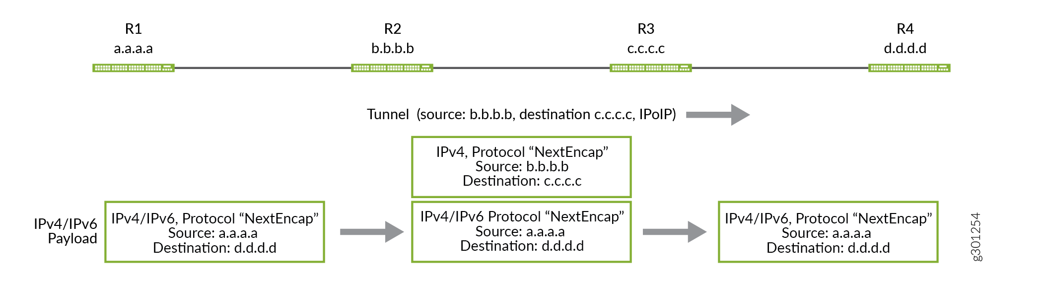
次の図は、R-2 と R-4 の間に確立された IP over IP トンネルを介して、IPv4 または IPv6 トラフィックが R-1 から R-5 に送信される方法を示しています。
IP-over-IP トンネルスティッチング
Junos OSリリース21.3R1では、MX240、MX480、MX960、PTX1000、PTX10008、PTX10016およびQFX10002にIP-over-IPトンネルスティッチが導入されています。この機能を使用して、デバイス上のIP-over-IPトンネルを終端し、同じデバイス上で別のトンネルを開始することができます。デバイスが IP-over-IP パケットを受信すると、外側のパケット ヘッダーのカプセル化が解除され、内側のパケット ルックアップが行われます。その後、内部 IP パケット ヘッダーは同じデバイス上の別のトンネルを指し示し、同じデバイスが別の IP-over-IP ヘッダーでパケットを再度カプセル化します。
例:ネクストホップベースのIP-over-IP動的トンネルの設定
IP-over-IP カプセル化を使用して、ネクストホップベースのトンネルを設定する方法について説明します。
- 要件
- 概要
- プロトコルネクストホップによるIP-over-IP動的トンネルの設定
- 例:静的設定を使用してinetcolor.0を介して解決されるLDPトンネルを使用してMPLS環境でIPoIPトンネルを設定する
- 例:BGPシグナリングを使用してinetcolor.0を介して解決されるMPLSクラウドのLDPトンネルでIPoIPトンネルを設定する
- 検証
要件
この例では、以下のハードウェアとソフトウェアのコンポーネントを使用しています。
5つのMXシリーズルーター。
Junos OS リリース 20.3R1 以降のバージョン。
- サポートされているプラットフォームについては、 機能エクスプローラー を参照してください。
概要
Junos OS Release 20.3R1以降、IPトランスポートネットワーク上でのIPオーバーレイの構築を容易にするために、IP-over-IPカプセル化がサポートされています。この例では、OSPFコアを介して接続されたR2とR4の間のIBGPピアリングを介したプロトコルネクストホップ(PNH)を持つデバイス間でユニキャストIP-over-IPトンネルを確立し、ルートを交換して動的トンネルに信号を送る様子を示しています。
トポロジー
図 1 は、5 つのデバイスを使用した IP-over-IP のシナリオを示しています。
この例では、R2とR4の間に確立されたIP-over-IP動的トンネルを介して、R1からR5へ、またR1からR5へ、またはその逆のルートを交換しています。プロトコル IS-IS を使用して、R1 からのルートは R2 に、R5 からのルートは R4 にエクスポートされます。R2 から R4 に Tunnel-01 ユニキャスト IPIP トンネルを設定し、R4 から R2 に Tunnel-01 別のトンネルを設定します。ピアデバイスの設定された宛先ネットワークからネットワークマスク内で生成されたルートプレフィックスは、トンネルを作成するために使用され、トラフィックはトンネル内のルートとは逆方向に流れます。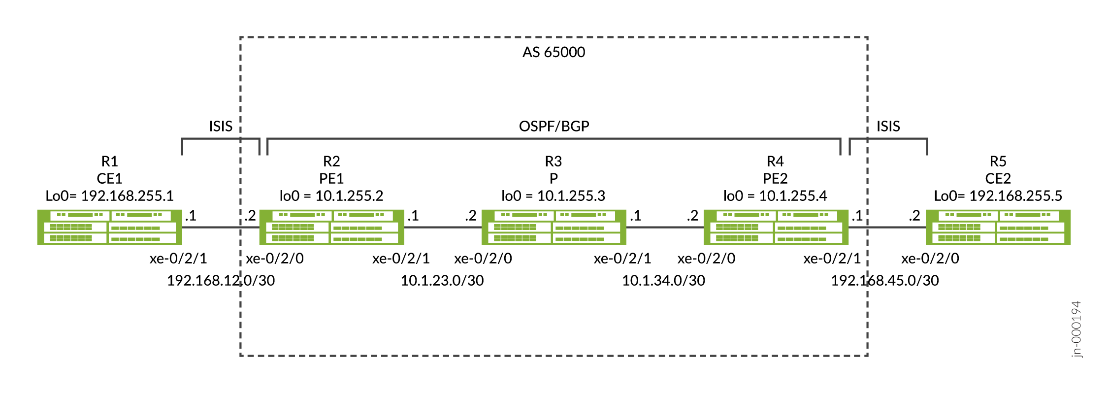
プロトコルネクストホップによるIP-over-IP動的トンネルの設定
CLIクイック構成
この例を迅速に設定するには、以下のコマンドをコピーして、テキスト ファイルに貼り付け、改行を削除し、ネットワーク設定に一致させる必要がある詳細情報を変更し、コマンドを 階[edit]層レベルで CLI にコピー アンド ペーストして、設定モードからコミットを入力します。
R1
set interfaces xe-0/2/0 unit 0 description R1-to-R2
set interfaces xe-0/2/0 unit 0 family inet address 192.168.12.1/30
set interfaces xe-0/2/0 unit 0 family iso
set interfaces lo0 unit 0 family inet address 192.168.255.1/32
set interfaces lo0 unit 0 family iso address 49.0001.1920.1682.5501.00
set routing-options router-id 192.168.255.1
set protocols isis interface xe-0/2/0.0
set protocols isis interface lo0.0
set protocols isis level 1 disable
R2
set interfaces xe-0/2/0 description R2-to-R1
set interfaces xe-0/2/0 unit 0 family inet address 192.168.12.2/30
set interfaces xe-0/2/0 unit 0 family iso
set interfaces xe-0/2/1 description R2-to-R3
set interfaces xe-0/2/1 unit 0 family inet address 10.1.23.1/30
set interfaces lo0 unit 0 family inet address 10.1.255.2/32
set interfaces lo0 unit 0 family iso address 49.0001.0010.1255.0002.00
set policy-options policy-statement export-bgp term t1 from protocol bgp
set policy-options policy-statement export-bgp term t1 then accept
set policy-options policy-statement export-isis term t1 from protocol isis
set policy-options policy-statement export-isis term t1 then next-hop self
set policy-options policy-statement export-isis term t1 then accept
set routing-options resolution rib inet.0 resolution-ribs inet.3
set routing-options router-id 10.1.255.2
set routing-options autonomous-system 65000
set routing-options dynamic-tunnels Tunnel-01 source-address 10.1.255.2
set routing-options dynamic-tunnels Tunnel-01 ipip
set routing-options dynamic-tunnels Tunnel-01 destination-networks 10.1.255.0/24
set protocols bgp group iBGP type internal
set protocols bgp group iBGP local-address 10.1.255.2
set protocols bgp group iBGP family inet unicast
set protocols bgp group iBGP export export-isis
set protocols bgp group iBGP neighbor 10.1.255.4
set protocols isis interface xe-0/2/0.0
set protocols isis interface lo0.0
set protocols isis level 1 disable
set protocols isis export export-bgp
set protocols ospf area 0.0.0.0 interface xe-0/2/1.0
set protocols ospf area 0.0.0.0 interface lo0.0
R3
set interfaces xe-0/2/0 unit 0 description R3-to-R2
set interfaces xe-0/2/0 unit 0 family inet address 10.1.23.2/30
set interfaces xe-0/2/1 unit 0 description R3-to-R4
set interfaces xe-0/2/1 unit 0 family inet address 10.1.34.1/30
set interfaces lo0 unit 0 family inet address 10.1.255.3/32
set routing-options router-id 10.1.255.3
set protocols ospf area 0.0.0.0 interface xe-0/2/0.0
set protocols ospf area 0.0.0.0 interface xe-0/2/1.0
set protocols ospf area 0.0.0.0 interface lo0.0 passive
R4
set interfaces xe-0/2/0 unit 0 description R4-to-R3
set interfaces xe-0/2/0 unit 0 family inet address 10.1.34.2/30
set interfaces xe-0/2/1 unit 0 description R4-to-R5
set interfaces xe-0/2/1 unit 0 family inet address 192.168.45.1/30
set interfaces xe-0/2/1 unit 0 family iso
set interfaces lo0 unit 0 family inet address 10.1.255.4/32
set interfaces lo0 unit 0 family iso address 49.0001.0010.1255.0004.00
set policy-options policy-statement export-bgp term t1 from protocol bgp
set policy-options policy-statement export-bgp term t1 then accept
set policy-options policy-statement export-isis term t1 from protocol isis
set policy-options policy-statement export-isis term t1 then next-hop self
set policy-options policy-statement export-isis term t1 then accept
set routing-options resolution rib inet.0 resolution-ribs inet.3
set routing-options router-id 10.1.255.4
set routing-options autonomous-system 65000
set routing-options dynamic-tunnels Tunnel-01 source-address 10.1.255.4
set routing-options dynamic-tunnels Tunnel-01 ipip
set routing-options dynamic-tunnels Tunnel-01 destination-networks 10.1.255.0/24
set protocols bgp group iBGP type internal
set protocols bgp group iBGP local-address 10.1.255.4
set protocols bgp group iBGP family inet unicast
set protocols bgp group iBGP export export-isis
set protocols bgp group iBGP neighbor 10.1.255.2
set protocols isis interface xe-0/2/1.0
set protocols isis interface lo0.0
set protocols isis level 1 disable
set protocols isis export export-bgp
set protocols ospf area 0.0.0.0 interface xe-0/2/0.0
set protocols ospf area 0.0.0.0 interface lo0.0
R5
set interfaces xe-0/2/0 unit 0 description R5-to-R4
set interfaces xe-0/2/0 unit 0 family inet address 192.168.45.2/30
set interfaces xe-0/2/0 unit 0 family iso
set interfaces lo0 unit 0 family inet address 192.168.255.5/32
set interfaces lo0 unit 0 family iso address 49.0001.1920.1682.5505.00
set routing-options router-id 192.168.255.5
set protocols isis interface xe-0/2/0.0
set protocols isis interface lo0.0
set protocols isis level 1 disable
プロトコルネクストホップを使用したIP-IP動的トンネルの設定
R1のステップバイステップ手順
R1 と R5 の構成は似ているため、R1 の手順のみを示します。
-
R1で設定モードに入ります。
-
R2に接続されたインターフェイスとインターフェイスlo0を設定します。ファミリー
inetとisoの両方を設定してください。プロトコル IS-IS にはファミリーisoが必要です。[edit] user@R1# set interfaces xe-0/2/0 unit 0 description R1-to-R2 user@R1# set interfaces xe-0/2/0 unit 0 family inet address 192.168.12.1/30 user@R1# set interfaces xe-0/2/0 unit 0 family iso user@R1# set interfaces lo0 unit 0 family inet address 192.168.255.1/32 user@R1# set interfaces lo0 unit 0 family iso address 49.0001.1920.1682.5501.00
-
ルーターIDを設定します。
[edit]
user@R1# set routing-options router-id 192.168.255.1
-
プロトコル IS-IS を設定します。ルートは、IS-IS プロトコルを使用して R1 と R2 の間でアドバタイズされます。
[edit]
user@R1# set protocols isis interface xe-0/2/0.0
user@R1# set protocols isis interface lo0.0
user@R1# set protocols isis level 1 disable
-
コンフィギュレーションモードからR1に
commitを入力します。
R2のステップバイステップ手順
R2 と R4 の構成は似ているため、R2 の手順のみを順を追って説明します。
-
R2で設定モードに入ります。
-
R1 および R3 に接続するインターフェイスとインターフェイス lo0 を設定します。R1とlo0に接続されたインターフェイスで
inetfamilyとisoの両方を設定してください。[edit] user@R2# set interfaces xe-0/2/0 description R2-to-R1 user@R2# set interfaces xe-0/2/0 unit 0 family inet address 192.168.12.2/30 user@R2# set interfaces xe-0/2/0 unit 0 family iso user@R2# set interfaces xe-0/2/1 description R2-to-R3 user@R2# set interfaces xe-0/2/1 unit 0 family inet address 10.1.23.1/30 user@R2# set interfaces lo0 unit 0 family inet address 10.1.255.2/32 user@R2# set interfaces lo0 unit 0 family iso address 49.0001.0010.1255.0002.00
-
R1 に接続されたインタフェースのプロトコル IS-IS を設定します。BGPルートをIS-ISにアドバタイズするためのエクスポートポリシーは、ポリシー設定ステップに示されています。
[edit]
user@R2# set protocols isis interface xe-0/2/0.0
user@R2# set protocols isis interface lo0.0
user@R2# set protocols isis level 1 disable
user@R2# set protocols isis export export-bgp
-
lo0到達可能性のために、R3に接続されたインターフェイスのOSPFプロトコルを設定します。
[edit]
user@R2# set protocols ospf area 0.0.0.0 interface xe-0/2/1.0
user@R2# set protocols ospf area 0.0.0.0 interface lo0.0
-
R2 と R4 の間に
router-idとautonomous-system、および IBGP を設定します。IS-IS ルートを BGP にアドバタイズするためのエクスポートポリシーは、ポリシー設定ステップに示されています。[edit] user@R2# set routing-options router-id 10.1.255.2 user@R2# set routing-options autonomous-system 65000 user@R2# set protocols bgp group iBGP type internal user@R2# set protocols bgp group iBGP local-address 10.1.255.2 user@R2# set protocols bgp group iBGP family inet unicast user@R2# set protocols bgp group iBGP export export-isis user@R2# set protocols bgp group iBGP neighbor 10.1.255.4
-
前の手順で適用した BGP および IS-IS のエクスポート ポリシーを設定します。
export-bgpポリシーは、BGPルートをIS-ISにアドバタイズするためのエクスポートとしてプロトコルIS-ISに適用され、export-isisポリシーは、IS-ISルートをBGPにアドバタイズするためのエクスポートとしてBGPに適用されます。ネクストホップセルフオプションを使用すると、R2は、R1のインターフェイスネクストホップではなく、R2をネクストホップとして、IS-ISルートをBGPにアドバタイズできます。[edit] user@R2# set policy-options policy-statement export-bgp term t1 from protocol bgp user@R2# set policy-options policy-statement export-bgp term t1 then accept user@R2# set policy-options policy-statement export-isis term t1 from protocol isis user@R2# set policy-options policy-statement export-isis term t1 then next-hop self user@R2# set policy-options policy-statement export-isis term t1 then accept
-
IP-IP 動的トンネル Tunnel-01 を R2 から R4 に設定します。設定オプション
resolution-ribs inet.3では、inet.3 でルート解決を行うことができ、トンネルを確立するために必要です。[edit] user@R2# set routing-options resolution rib inet.0 resolution-ribs inet.3 user@R2# set routing-options dynamic-tunnels Tunnel-01 source-address 10.1.255.2 user@R2# set routing-options dynamic-tunnels Tunnel-01 ipip user@R2# set routing-options dynamic-tunnels Tunnel-01 destination-networks 10.1.255.0/24
-
(オプション):R2からR4に Tunnel-01 IP-IP動的トンネルの代替設定。
resolution-ribs inet.3を設定する代わりに、トンネル エンドポイントへのルートのプロトコル ネクストホップ プリファレンスよりも低いトンネル プリファレンスを設定することができます。R4 のルートは OSPF を使用して学習され、プリファレンスは 10 で、トンネルのデフォルト プリファレンスは 305 です。トンネルのプリファレンスを OSPF プリファレンスよりも低く設定することで、トンネルを優先して確立することができます。[edit] user@R2# set routing-options dynamic-tunnels Tunnel-01 source-address 10.1.255.2 user@R2# set routing-options dynamic-tunnels Tunnel-01 ipip user@R2# set routing-options dynamic-tunnels Tunnel-01 destination-networks 10.1.255.0/24 preference 9
-
R2 の設定モードから
commitを入力します。
R3のステップバイステップ手順
-
R3で設定モードに入ります。
-
R2 および R4 に接続するインターフェイスとインターフェイス lo0 を設定します。
[edit]
user@R3# set interfaces xe-0/2/0 unit 0 description R3-to-R2
user@R3# set interfaces xe-0/2/0 unit 0 family inet address 10.1.23.2/30
user@R3# set interfaces xe-0/2/1 unit 0 description R3-to-R4
user@R3# set interfaces xe-0/2/1 unit 0 family inet address 10.1.34.1/30
user@R3# set interfaces lo0 unit 0 family inet address 10.1.255.3/32
-
ルーターIDを設定します。
[edit]
user@R3# set routing-options router-id 10.1.255.3
-
lo0 到達可能性のために、R2 および R4 に接続されたインターフェイスの OSPF プロトコルを設定します。
[edit]
user@R3# set protocols ospf area 0.0.0.0 interface xe-0/2/0.0
user@R3# set protocols ospf area 0.0.0.0 interface xe-0/2/1.0
user@R3# set protocols ospf area 0.0.0.0 interface lo0.0 passive
-
R3 デバイスで設定モードから
commitを入力します。
結果
以下のようなデバイスで、以下の設定を照合して、設定を検証します。
R2 での設定を検証する方法は、以下のようになります。
user@R2# show interfaces
xe-0/2/0 {
    description R2-to-R1;
    unit 0 {
        family inet {
            address 192.168.12.2/30;
        }
        family iso;
    }
}
xe-0/2/1 {
    description R2-to-R3;
    unit 0 {
        family inet {
            address 10.1.23.1/30;
        }
    }
}
lo0 {
    unit 0 {
        family inet {
            address 10.1.255.2/32;
        }
        family iso {
            address 49.0001.0010.1255.0002.00;
        }
    }
}
user@R2# show routing-options
resolution {
    rib inet.0 {
        resolution-ribs inet.3;
    }
}
router-id 10.1.255.2;
autonomous-system 65000;
dynamic-tunnels {
    Tunnel-01 {
        source-address 10.1.255.2;
        ipip;
        destination-networks {
            10.1.255.0/24;
        }
    }
}
user@R2# show protocols
bgp {
    group iBGP {
        type internal;
        local-address 10.1.255.2;
        family inet {
            unicast;
        }
        export export-isis;
        neighbor 10.1.255.4;
    }
}
isis {
    interface xe-0/2/0.0;
    interface lo0.0;
    level 1 disable;
    export export-bgp;
}
ospf {
    area 0.0.0.0 {
        interface xe-0/2/1.0;
        interface lo0.0;
    }
}
user@R2# show policy-options
policy-statement export-bgp {
    term t1 {
        from protocol bgp;
        then accept;
    }
}
policy-statement export-isis {
    term t1 {
        from protocol isis;
        then {
            next-hop self;
            accept;
        }
    }
}
検証
動的トンネル データベースの確認
目的
動的トンネル データベースの情報を確認するには、 show dynamic-tunnels database 運用モード コマンドを使用します。
アクション
user@R2> show dynamic-tunnels database
*- Signal Tunnels #- PFE-down
Table: inet.3

Destination-network: 10.1.255.0/24

Tunnel to: 10.1.255.4/32
  Reference count: 3
  Next-hop type: IPoIP (forwarding-nexthop)
    Source address: 10.1.255.2
    Next hop: tunnel-composite, 0x76b6c50, nhid 515
      Reference count: 2
      Ingress Route: [OSPF] 10.1.255.4/32, via metric 2
      Traffic Statistics: Packets 0, Bytes 0
      State: Up
  Aggregate Traffic Statistics:
    Tunnel Encapsulation: Dest 10.1.255.4, Src 10.1.255.2, IPoIP, Tunnel-Id 1
Traffic Statistics: Packets 0, Bytes 0 user@R4> show dynamic-tunnels database
*- Signal Tunnels #- PFE-down
Table: inet.3
Destination-network: 10.1.255.0/24
Tunnel to: 10.1.255.2/32
Reference count: 3
Next-hop type: IPoIP (forwarding-nexthop)
Source address: 10.1.255.4
Next hop: tunnel-composite, 0x76b6c50, nhid 513
Reference count: 2
Ingress Route: [OSPF] 10.1.255.2/32, via metric 2
Traffic Statistics: Packets 0, Bytes 0
State: Up
Aggregate Traffic Statistics:
Tunnel Encapsulation: Dest 10.1.255.2, Src 10.1.255.4, IPoIP, Tunnel-Id 1
Traffic Statistics: Packets 0, Bytes 0意味
この出力は、R2(192.168.0.21 送信元)とR4(192.168.0.41 宛先)の間にIPoIPトンネルが確立され、R4(192.168.0.41 送信元)とR2(192.168.0.21 宛先)の間に別のIPoIPトンネルが確立されていることを示しています。
inet.3でルートテーブルを検証
目的
inet.3テーブルで生成されたルートを検証するには、 show route table inet.3 operational modeコマンドを使用します。
アクション
user@R2> show route table inet.3

inet.3: 2 destinations, 2 routes (2 active, 0 holddown, 0 hidden)
+ = Active Route, - = Last Active, * = Both

10.1.255.0/24      *[Tunnel/305] 02:02:44
                       Tunnel
10.1.255.4/32      *[Tunnel/305] 02:02:44, metric 2
Tunnel Composite, IPoIP (src 10.1.255.2 dest 10.1.255.4)user@R4> show route table inet.3
inet.3: 2 destinations, 2 routes (2 active, 0 holddown, 0 hidden)
+ = Active Route, - = Last Active, * = Both
10.1.255.0/24 *[Tunnel/305] 6d 01:35:50
Tunnel
10.1.255.2/32 *[Tunnel/305] 6d 01:35:48, metric 2
Tunnel Composite, IPoIP (src 10.1.255.4 dest 10.1.255.2)意味
出力には、トンネルを使用するBGPトラフィックの解決に使用されるルートが表示されます。
トンネルを使用した BGP ルートの検証
目的
R1とR5のR2とR4で受信したBGPルートがトンネルを使用していることを確認するため。
アクション
user@R2> show route protocol bgp

inet.0: 17 destinations, 17 routes (17 active, 0 holddown, 0 hidden)
+ = Active Route, - = Last Active, * = Both

192.168.255.5/32   *[BGP/170] 02:42:48, MED 10, localpref 100, from 10.1.255.4
                      AS path: I, validation-state: unverified
                    >  via Tunnel Composite, IPoIP (src 10.1.255.2 dest 10.1.255.4)

inet.3: 2 destinations, 2 routes (2 active, 0 holddown, 0 hidden)

iso.0: 1 destinations, 1 routes (1 active, 0 holddown, 0 hidden)

inet6.0: 1 destinations, 1 routes (1 active, 0 holddown, 0 hidden)user@R4> show route protocol bgp
inet.0: 17 destinations, 17 routes (17 active, 0 holddown, 0 hidden)
+ = Active Route, - = Last Active, * = Both
192.168.255.1/32 *[BGP/170] 00:13:30, MED 10, localpref 100, from 10.1.255.2
AS path: I, validation-state: unverified
> via Tunnel Composite, IPoIP (src 10.1.255.4 dest 10.1.255.2)
inet.3: 2 destinations, 2 routes (2 active, 0 holddown, 0 hidden)
iso.0: 1 destinations, 1 routes (1 active, 0 holddown, 0 hidden)
inet6.0: 1 destinations, 1 routes (1 active, 0 holddown, 0 hidden)意味
出力は、R2 が R5 への BGP ルートにトンネルを使用し、R4 が R1 への BGP ルートにトンネルを使用していることを示しています。
エンドツーエンドの到達可能性の確認
目的
ping 192.168.255.5 source 192.168.255.1 count 2 運用モードコマンドを使用して、R1 が R5 に ping できることを確認します。
アクション
user@R1>ping 192.168.255.5 source 192.168.255.1 count 2
PING 192.168.255.5 (192.168.255.5): 56 data bytes
64 bytes from 192.168.255.5: icmp_seq=0 ttl=62 time=5.565 ms
64 bytes from 192.168.255.5: icmp_seq=1 ttl=62 time=5.957 ms

--- 192.168.255.5 ping statistics ---
2 packets transmitted, 2 packets received, 0% packet loss
round-trip min/avg/max/stddev = 5.565/5.761/5.957/0.196 ms
意味
R1からの出力は、R1がR5にpingできることを示しています。
例:静的設定を使用してinetcolor.0を介して解決されるLDPトンネルを使用してMPLS環境でIPoIPトンネルを設定する
デフォルトでは、MPLSはIPよりも優先されます。たとえば、MPLS と LDP を R2、R3、R4 で設定し、R2 は R4 から LDP 経由で到達可能である場合、R2 からのルートは優先度が高いため、IP-over-IP ではなく LDP 経由で解決されます。
特定のルートをLDPではなくIP-over-IP経由で解決したい場合は、IP-over-IPの方が優先度の高いinetcolorテーブルを作成し、inet3テーブルではなくinetcolorテーブル経由でそのルートを解決するようにBGPを設定します。次の例は、静的構成を使用してこれを行う方法を示しています。
トポロジー
この例では、R2とR4の間に確立されたIP-over-IP動的トンネルを介して、R1からR5へ、またR1からR5へ、またはその逆のルートを交換しています。プロトコル IS-IS を使用して、R1 からのルートは R2 に、R5 からのルートは R4 にエクスポートされます。R2 から R4 に Tunnel-01 ユニキャスト IPIP トンネルを設定し、R4 から R2 に Tunnel-01 別のトンネルを設定します。ピアデバイスの設定された宛先ネットワークからネットワークマスク内で生成されたルートプレフィックスは、トンネルを作成するために使用され、トラフィックはトンネル内のルートと反対方向に流れます。
CLIクイック構成
R1
set interfaces xe-0/2/0 unit 0 description R1-to-R2
set interfaces xe-0/2/0 unit 0 family inet address 192.168.12.1/30
set interfaces xe-0/2/0 unit 0 family iso
set interfaces lo0 unit 0 family inet address 192.168.255.1/32
set interfaces lo0 unit 0 family iso address 49.0001.1920.1682.5501.00
set routing-options router-id 192.168.255.1
set protocols isis interface xe-0/2/0.0
set protocols isis interface lo0.0
set protocols isis level 1 disable
R2
set interfaces xe-0/2/0 description R2-to-R1
set interfaces xe-0/2/0 unit 0 family inet address 192.168.12.2/30
set interfaces xe-0/2/0 unit 0 family iso
set interfaces xe-0/2/1 description R2-to-R3
set interfaces xe-0/2/1 unit 0 family inet address 10.1.23.1/30
set interfaces xe-0/2/1 unit 0 family mpls
set interfaces lo0 unit 0 family inet address 10.1.255.2/32
set interfaces lo0 unit 0 family iso address 49.0001.0010.1255.0002.00
set policy-options policy-statement export-bgp term t1 from protocol bgp
set policy-options policy-statement export-bgp term t1 then accept
set policy-options policy-statement export-isis term t1 from protocol isis
set policy-options policy-statement export-isis term t1 then next-hop self
set policy-options policy-statement export-isis term t1 then accept
set policy-options policy-statement ipip-tunnel-color term term-01 from route-filter 192.168.255.5/32 exact
set policy-options policy-statement ipip-tunnel-color term term-01 then community add red
set policy-options policy-statement ipip-tunnel-color term term-01 then accept
set policy-options policy-statement set-dynamic-tunnel-ep term t1 from route-filter 10.1.255.4/32 exact
set policy-options policy-statement set-dynamic-tunnel-ep term t1 then tunnel-end-point-address 10.1.255.4
set policy-options policy-statement set-dynamic-tunnel-ep term t1 then accept
set policy-options community red members color:0:100
set routing-options router-id 10.1.255.2
set routing-options autonomous-system 65000
set routing-options dynamic-tunnels Tunnel-01 source-address 10.1.255.2
set routing-options dynamic-tunnels Tunnel-01 ipip
set routing-options dynamic-tunnels Tunnel-01 destination-networks 10.1.255.0/24 dyn-tunnel-attribute-policy set-dynamic-tunnel-ep
set routing-options dynamic-tunnels Tunnel-01 destination-networks 10.1.255.0/24 colors 100
set protocols bgp group iBGP type internal
set protocols bgp group iBGP local-address 10.1.255.2
set protocols bgp group iBGP import ipip-tunnel-color
set protocols bgp group iBGP family inet unicast extended-nexthop-color
set protocols bgp group iBGP export export-isis
set protocols bgp group iBGP neighbor 10.1.255.4
set protocols isis interface xe-0/2/0.0
set protocols isis interface lo0.0
set protocols isis level 1 disable
set protocols isis export export-bgp
set protocols ldp interface xe-0/2/1.0
set protocols mpls interface xe-0/2/1.0
set protocols ospf area 0.0.0.0 interface xe-0/2/1.0
set protocols ospf area 0.0.0.0 interface lo0.0
R3
set interfaces xe-0/2/0 unit 0 description R3-to-R2
set interfaces xe-0/2/0 unit 0 family inet address 10.1.23.2/30
set interfaces xe-0/2/0 unit 0 family mpls
set interfaces xe-0/2/1 unit 0 description R3-to-R4
set interfaces xe-0/2/1 unit 0 family inet address 10.1.34.1/30
set interfaces xe-0/2/1 unit 0 family mpls
set interfaces lo0 unit 0 family inet address 10.1.255.3/32
set routing-options router-id 10.1.255.3
set protocols ldp interface xe-0/2/0.0
set protocols ldp interface xe-0/2/1.0
set protocols mpls interface xe-0/2/0.0
set protocols mpls interface xe-0/2/1.0
set protocols ospf area 0.0.0.0 interface xe-0/2/0.0
set protocols ospf area 0.0.0.0 interface xe-0/2/1.0
set protocols ospf area 0.0.0.0 interface lo0.0 passive
R4
set interfaces xe-0/2/0 unit 0 description R4-to-R3
set interfaces xe-0/2/0 unit 0 family inet address 10.1.34.2/30
set interfaces xe-0/2/0 unit 0 family mpls
set interfaces xe-0/2/1 unit 0 description R4-to-R5
set interfaces xe-0/2/1 unit 0 family inet address 192.168.45.1/30
set interfaces xe-0/2/1 unit 0 family iso
set interfaces lo0 unit 0 family inet address 10.1.255.4/32
set interfaces lo0 unit 0 family iso address 49.0001.0010.1255.0004.00
set policy-options policy-statement export-bgp term t1 from protocol bgp
set policy-options policy-statement export-bgp term t1 then accept
set policy-options policy-statement export-isis term t1 from protocol isis
set policy-options policy-statement export-isis term t1 then next-hop self
set policy-options policy-statement export-isis term t1 then accept
set policy-options policy-statement ipip-tunnel-color term term-01 from route-filter 192.168.255.1/32 exact
set policy-options policy-statement ipip-tunnel-color term term-01 then community add red
set policy-options policy-statement ipip-tunnel-color term term-01 then accept
set policy-options policy-statement set-dynamic-tunnel-ep term t1 from route-filter 10.1.255.2/32 exact
set policy-options policy-statement set-dynamic-tunnel-ep term t1 then tunnel-end-point-address 10.1.255.2
set policy-options policy-statement set-dynamic-tunnel-ep term t1 then accept
set policy-options community red members color:0:100
set routing-options router-id 10.1.255.4
set routing-options autonomous-system 65000
set routing-options dynamic-tunnels Tunnel-01 source-address 10.1.255.4
set routing-options dynamic-tunnels Tunnel-01 ipip
set routing-options dynamic-tunnels Tunnel-01 destination-networks 10.1.255.0/24 dyn-tunnel-attribute-policy set-dynamic-tunnel-ep
set routing-options dynamic-tunnels Tunnel-01 destination-networks 10.1.255.0/24 colors 100
set protocols bgp group iBGP type internal
set protocols bgp group iBGP local-address 10.1.255.4
set protocols bgp group iBGP import ipip-tunnel-color
set protocols bgp group iBGP family inet unicast extended-nexthop-color
set protocols bgp group iBGP export export-isis
set protocols bgp group iBGP neighbor 10.1.255.2
set protocols isis interface xe-0/2/1.0
set protocols isis interface lo0.0
set protocols isis level 1 disable
set protocols isis export export-bgp
set protocols ldp interface xe-0/2/0.0
set protocols mpls interface xe-0/2/0.0
set protocols ospf area 0.0.0.0 interface xe-0/2/0.0
set protocols ospf area 0.0.0.0 interface lo0.0
R5
set interfaces xe-0/2/0 unit 0 description R5-to-R4
set interfaces xe-0/2/0 unit 0 family inet address 192.168.45.2/30
set interfaces xe-0/2/0 unit 0 family iso
set interfaces lo0 unit 0 family inet address 192.168.255.5/32
set interfaces lo0 unit 0 family iso address 49.0001.1920.1682.5505.00
set routing-options router-id 192.168.255.5
set protocols isis interface xe-0/2/0.0
set protocols isis interface lo0.0
set protocols isis level 1 disable
手順
R1のステップバイステップ手順
R1 と R5 の構成は似ているため、R1 の手順のみを示します。
-
R1で設定モードに入ります。
-
R2に接続されたインターフェイスとインターフェイスlo0を設定します。ファミリー
inetとisoの両方を設定してください。プロトコル IS-IS にはファミリーisoが必要です。[edit] user@R1# set interfaces xe-0/2/0 unit 0 description R1-to-R2 user@R1# set interfaces xe-0/2/0 unit 0 family inet address 192.168.12.1/30 user@R1# set interfaces xe-0/2/0 unit 0 family iso user@R1# set interfaces lo0 unit 0 family inet address 192.168.255.1/32 user@R1# set interfaces lo0 unit 0 family iso address 49.0001.1920.1682.5501.00
-
ルーターIDを設定します。
[edit]
user@R1# set routing-options router-id 192.168.255.1
-
プロトコル IS-IS を設定します。ルートは、IS-IS プロトコルを使用して R1 と R2 の間でアドバタイズされます。
[edit]
user@R1# set protocols isis interface xe-0/2/0.0
user@R1# set protocols isis interface lo0.0
user@R1# set protocols isis level 1 disable
-
コンフィギュレーションモードからR1に
commitを入力します。
R2のステップバイステップ手順
R2 と R4 の構成は似ているため、R2 の手順のみを順を追って説明します。
-
R2で設定モードに入ります。
-
R1 および R3 に接続するインターフェイスとインターフェイス lo0 を設定します。R1 と lo0 に接続されたインターフェイスで family
inetとisoの両方を設定し、R3 に接続されたインターフェイスで familyinetとmplsの両方を設定していることを確認します。[edit] user@R2# set interfaces xe-0/2/0 description R2-to-R1 user@R2# set interfaces xe-0/2/0 unit 0 family inet address 192.168.12.2/30 user@R2# set interfaces xe-0/2/0 unit 0 family iso user@R2# set interfaces xe-0/2/1 description R2-to-R3 user@R2# set interfaces xe-0/2/1 unit 0 family inet address 10.1.23.1/30 user@R2# set interfaces xe-0/2/0 unit 0 family mpls user@R2# set interfaces lo0 unit 0 family inet address 10.1.255.2/32 user@R2# set interfaces lo0 unit 0 family iso address 49.0001.0010.1255.0002.00
-
R1 に接続されたインタフェースのプロトコル IS-IS を設定します。BGPルートをIS-ISにアドバタイズするためのエクスポートポリシーは、ポリシー設定ステップに示されています。
[edit]
user@R2# set protocols isis interface xe-0/2/0.0
user@R2# set protocols isis interface lo0.0
user@R2# set protocols isis level 1 disable
user@R2# set protocols isis export export-bgp
-
lo0到達可能性のために、R3に接続されたインターフェイスのOSPFプロトコルを設定します。
[edit]
user@R2# set protocols ospf area 0.0.0.0 interface xe-0/2/1.0
user@R2# set protocols ospf area 0.0.0.0 interface lo0.0
-
R3 に接続されたインタフェースの LDP および MPLS プロトコルを設定します。
[edit]
user@R2# set protocols ldp interface xe-0/2/1.0
user@R2# set protocols mpls interface xe-0/2/1.0
-
routing-options階層下のrouter-idとautonomous-systemを設定し、R2 と R4 の間で IBGP を設定します。BGPを使用して学習したルートにコミュニティを追加するインポートポリシーと、IS-ISルートをBGPにアドバタイズするエクスポートポリシーは、ポリシー設定ステップに示されています。inetcolor.0 テーブルを使用して解決できるようにextended-nexthop-colorオプションをfamily inet unicast構成に必ず含めてください。[edit] user@R2# set routing-options router-id 10.1.255.2 user@R2# set routing-options autonomous-system 65000 user@R2# set protocols bgp group iBGP type internal user@R2# set protocols bgp group iBGP local-address 10.1.255.2 user@R2# set protocols bgp group iBGP import ipip-tunnel-color user@R2# set protocols bgp group iBGP family inet unicast extended-nexthop-color user@R2# set protocols bgp group iBGP export export-isis user@R2# set protocols bgp group iBGP neighbor 10.1.255.4
-
IP-IP 動的トンネル Tunnel-01 を R2 から R4 に設定します。
colors設定オプションを使用すると、inetcolor.0ルートテーブルにトンネルを作成できます。dyn-tunnel-attribute-policyset-dynamic-tunnel-epは、静的トンネルのエンドポイントを設定します。ポリシーは、ポリシー設定手順で表示されます。[edit] user@R2# set routing-options dynamic-tunnels Tunnel-01 source-address 10.1.255.2 user@R2# set routing-options dynamic-tunnels Tunnel-01 ipip user@R2# set routing-options dynamic-tunnels Tunnel-01 destination-networks 10.1.255.0/24 dyn-tunnel-attribute-policy set-dynamic-tunnel-ep user@R2# set routing-options dynamic-tunnels Tunnel-01 destination-networks 10.1.255.0/24 colors 100
-
前の構成手順で適用したポリシーを構成します。export-bgpポリシーは、BGPルートをIS-ISにアドバタイズします。export-isisポリシーは、ネクストホップをR2に変更して、IS-ISルートをBGPにアドバタイズします。ipip-tunnel-colorポリシーは、動的トンネルの
colors設定で一致するルートにコミュニティを適用します。set-dynamic-tunnel-epポリシーは、R4をトンネルのエンドポイントとして設定します。[edit] user@R2# set policy-options policy-statement export-bgp term t1 from protocol bgp user@R2# set policy-options policy-statement export-bgp term t1 then accept user@R2# set policy-options policy-statement export-isis term t1 from protocol isis user@R2# set policy-options policy-statement export-isis term t1 then next-hop self user@R2# set policy-options policy-statement export-isis term t1 then accept user@R2# set policy-options policy-statement ipip-tunnel-color term term-01 from route-filter 192.168.255.5/32 exact user@R2# set policy-options policy-statement ipip-tunnel-color term term-01 then community add red user@R2# set policy-options policy-statement ipip-tunnel-color term term-01 then accept user@R2# set policy-options policy-statement set-dynamic-tunnel-ep term t1 from route-filter 10.1.255.4/32 exact user@R2# set policy-options policy-statement set-dynamic-tunnel-ep term t1 then tunnel-end-point-address 10.1.255.4 user@R2# set policy-options policy-statement set-dynamic-tunnel-ep term t1 then accept user@R2# set policy-options community red members color:0:100
-
設定モード
commitからを入力します。
R3のステップバイステップ手順
-
R3で設定モードに入ります。
-
R2 および R4 に接続するインターフェイスとインターフェイス lo0 を設定します。R2とR4に接続されたインターフェイスにファミリー
inetとmplsの両方を設定してください。[edit] user@R3# set interfaces xe-0/2/0 unit 0 description R3-to-R2 user@R3# set interfaces xe-0/2/0 unit 0 family inet address 10.1.23.2/30 user@R3# set interfaces xe-0/2/0 unit 0 family mpls user@R3# set interfaces xe-0/2/1 unit 0 description R3-to-R4 user@R3# set interfaces xe-0/2/1 unit 0 family inet address 10.1.34.1/30 user@R3# set interfaces xe-0/2/1 unit 0 family mpls user@R3# set interfaces lo0 unit 0 family inet address 10.1.255.3/32
-
ルーターIDを設定します。
[edit]
user@R3# set routing-options router-id 10.1.255.3
-
lo0 到達可能性のために、R2 および R4 に接続されたインターフェイスの OSPF プロトコルを設定します。
[edit]
user@R3# set protocols ospf area 0.0.0.0 interface xe-0/2/0.0
user@R3# set protocols ospf area 0.0.0.0 interface xe-0/2/1.0
user@R3# set protocols ospf area 0.0.0.0 interface lo0.0 passive
-
R2 および R4 に接続するインタフェースの LDP および MPLS プロトコルを設定します。
[edit]
user@R2# set protocols ldp interface xe-0/2/0.0
user@R2# set protocols ldp interface xe-0/2/1.0
user@R2# set protocols mpls interface xe-0/2/0.0
user@R2# set protocols mpls interface xe-0/2/1.0
-
R3 デバイスで設定モードから
commitを入力します。
結果
デバイスから以下の設定を確認して、設定を検証します。
R2の設定を確認する方法は、以下のようになります。
user@R2# show interfaces
xe-0/2/0 {
    description R2-to-R1;
    unit 0 {
        family inet {
            address 192.168.12.2/30;
        }
        family iso;
    }
}
xe-0/2/1 {
    description R2-to-R3;
    unit 0 {
        family inet {
            address 10.1.23.1/30;
        }
        family mpls;
    }
}
lo0 {
    apply-groups-except global;
    unit 0 {
        family inet {
            address 10.1.255.2/32;
        }
        family iso {
            address 49.0001.0010.1255.0002.00;
        }
    }
}
user@R2# show protocols
bgp {
    group iBGP {
        type internal;
        local-address 10.1.255.2;
        import ipip-tunnel-color;
        family inet {
            unicast {
                extended-nexthop-color;
            }
        }
        export export-isis;
        neighbor 10.1.255.4;
    }
}
isis {
    interface xe-0/2/0.0;
    interface lo0.0;
    level 1 disable;
    export export-bgp;
}
ldp {
    interface xe-0/2/1.0;
}
mpls {
    interface xe-0/2/1.0;
}
ospf {
    area 0.0.0.0 {
        interface xe-0/2/1.0;
        interface lo0.0;
    }
}
user@R2#show routing-options
router-id 10.1.255.2;
autonomous-system 65000;
dynamic-tunnels {
    Tunnel-01 {
        source-address 10.1.255.2;
        ipip;
        destination-networks {
            10.1.255.0/24 {
                dyn-tunnel-attribute-policy set-dynamic-tunnel-ep;
                colors 100;
            }
        }
    }
}
user@R2#show policy-options
policy-statement export-bgp {
    term t1 {
        from protocol bgp;
        then accept;
    }
}
policy-statement export-isis {
    term t1 {
        from protocol isis;
        then {
            next-hop self;
            accept;
        }
    }
}
policy-statement ipip-tunnel-color {
    term term-01 {
        from {
            route-filter 192.168.255.5/32 exact;
        }
        then {
            community add red;
            accept;
        }
    }
}
policy-statement set-dynamic-tunnel-ep {
    term t1 {
        from {
            route-filter 10.1.255.4/32 exact;
        }
        then {
            tunnel-end-point-address 10.1.255.4;
            accept;
        }
    }
}
community red members color:0:100;
検証
ルート解決の検証
目的
inet.3テーブルとinetcolor.0テーブルの両方でルートのルート解決を検証するには、 show route table inet.3 および show route table inetcolor.0 運用モードコマンドを使用します。
アクション
user@R2> show route table inet.3

inet.3: 3 destinations, 4 routes (3 active, 0 holddown, 0 hidden)
+ = Active Route, - = Last Active, * = Both

10.1.255.0/24      *[Tunnel/305] 00:12:21
                       Tunnel
10.1.255.3/32      *[LDP/9] 1d 19:37:01, metric 1
                    >  to 10.1.23.2 via xe-0/2/1.0
10.1.255.4/32      *[LDP/9] 1d 19:32:25, metric 1
                    >  to 10.1.23.2 via xe-0/2/1.0, Push 299792
                    [Tunnel/305] 00:13:38, metric 2
Tunnel Composite, IPoIP (src 10.1.255.2 dest 10.1.255.4)user@R2> show route table inetcolor.0
inetcolor.0: 2 destinations, 2 routes (2 active, 0 holddown, 0 hidden)
+ = Active Route, - = Last Active, * = Both
10.1.255.0-0<c>/24
*[Tunnel/305] 00:13:26
Tunnel
10.1.255.4-100<c>/64
*[Tunnel/305] 00:13:26, metric 2
Tunnel Composite, IPoIP (src 10.1.255.2 dest 10.1.255.4-100<c>)意味
R2 の出力は、inet.3 テーブルでは、IP-over-IP よりも優先度が高いため、ルート 10.1.255.4 が LDP によって解決されていることを示しています。一方、新しく作成されたinetcolor.0テーブルでは、ルート 10.1.255.4 は、 <c> が接続されたIP-over-IPトンネルを介して解決されています。
動的トンネル データベースの確認
目的
inetcolor.0テーブル内のルートによって作成されたIP-over-IP動的トンネルを確認するには、 show dynamic-tunnels database terse operational modeコマンドを使用します。
アクション
user@R2>show dynamic-tunnels database terse
*- Signal Tunnels #- PFE-down
Table: inet.3

Destination-network: 10.1.255.0/24

*- Signal Tunnels #- PFE-down
Table: inetcolor.0

Destination-network: 10.1.255.0-0<c>/24
Destination                      Source          Next-hop                 Type       Status
10.1.255.4-100<c>/64             10.1.255.2      0x76b71cc nhid 592       IPoIP      Up (via metric 2, tunnel-endpoint 10.1.255.4)
意味
R2出力は、ルート 192.168.0.41 がネクストホップベースの動的トンネルを作成したことを示しています。
ルートネクストホップの検証
目的
IP-over-IP で解決するように設定されたルートのすべてのネクストホップを検証するには、 show route 192.168.255.5 extensive expanded-nh 運用モード コマンドを使用します。
アクション
user@R2>show route 192.168.255.5 extensive expanded-nh

inet.0: 18 destinations, 18 routes (18 active, 0 holddown, 0 hidden)
192.168.255.5/32 (1 entry, 1 announced)
Installed-nexthop:
Indr Composite (0x76b7238) 10.1.255.4-100<c>
  Krt_cnh (0x6fb1928) Index:593
    Krt_inh (0x7164d3c) Index:1048575 PNH: 10.1.255.4-100<c>
      Tun-comp (0x76b71cc) Index:592 IPoIP src 10.1.255.2 dest 10.1.255.4-100<c> tunnel-endpoint 10.1.255.4
TSI:
KRT in-kernel 192.168.255.5/32 -> {composite(593)}
IS-IS level 2, LSP fragment 0
        *BGP    Preference: 170/-101
                Next hop type: Indirect, Next hop index: 0
                Address: 0x76b7238
                Next-hop reference count: 2
                Source: 10.1.255.4
                Next hop type: Tunnel Composite, Next hop index: 592
                Next hop: via Tunnel Composite, IPoIP (src 10.1.255.2 dest 10.1.255.4-100<c> tunnel-endpoint 10.1.255.4), selected
                Protocol next hop: 10.1.255.4-100<c>
                Composite next hop: 0x6fb1928 593 INH Session ID: 0
                Indirect next hop: 0x7164d3c 1048575 INH Session ID: 0
                State: <Active Int Ext>
                Local AS: 65000 Peer AS: 65000
                Age: 20:14      Metric: 10      Metric2: 2
                Validation State: unverified
                Task: BGP_65000.10.1.255.4
                Announcement bits (2): 0-KRT 5-IS-IS
                AS path: I
                Communities: color:0:100
                Accepted
                Localpref: 100
                Router ID: 10.1.255.4
                Route-nexthop:
                Indr (0x76b7238) 10.1.255.4-100<c>
                  Krt_cnh (0x6fb1928) Index:593
                    Krt_inh (0x7164d3c) Index:1048575
                      Tun-comp (0x76b71cc) Index:592
                Thread: junos-main
                Composite next hops: 1
                        Protocol next hop: 10.1.255.4-100<c> Metric: 2
                        Composite next hop: 0x6fb1928 593 INH Session ID: 0
                        Indirect next hop: 0x7164d3c 1048575 INH Session ID: 0
                        Indirect path forwarding next hops: 1
                                Next hop type: Tunnel Composite
                                Tunnel type: IPoIP, (forwarding-nexthop), Reference count: 2, nhid: 592
                                Destination address: 10.1.255.4-100<c>, Source address: 10.1.255.2
                                Tunnel endpoint: 10.1.255.4
                                10.1.255.4-100<c>/64 Originating RIB: inetcolor.0
                                  Metric: 2 Node path count: 1
                                  Forwarding nexthops: 1
                                        Next hop type: Tunnel Composite
                                        Tunnel type: IPoIP, (extended-attr), Reference count: 1, nhid: 0
                                        Destination address: 10.1.255.4-100<c>, Source address: 10.1.255.2
意味
R2からの出力では、 192.168.255.5 ルート用に拡張されたネクストホップが表示されています。R2はMXシリーズルーターであるため、プロトコルネクストホップと間接ネクストホップを送信します。
エンドツーエンドの到達可能性の確認
目的
ping 192.168.255.5 source 192.168.255.1 count 2 運用モードコマンドを使用して、R1 が R5 に ping できることを確認します。
アクション
user@R1>ping 192.168.255.5 source 192.168.255.1 count 2
PING 192.168.255.5 (192.168.255.5): 56 data bytes
64 bytes from 192.168.255.5: icmp_seq=0 ttl=62 time=6.009 ms
64 bytes from 192.168.255.5: icmp_seq=1 ttl=62 time=5.398 ms

--- 192.168.255.5 ping statistics ---
2 packets transmitted, 2 packets received, 0% packet loss
round-trip min/avg/max/stddev = 5.398/5.704/6.009/0.306 ms
意味
R1からの出力は、R1がR5にpingできることを示しています。
例:BGPシグナリングを使用してinetcolor.0を介して解決されるMPLSクラウドのLDPトンネルでIPoIPトンネルを設定する
LDP が有効な MPLS 環境では、MPLS は IP よりも優先されるため、BGP ルートは inet.3 テーブル上の LDP を介して解決されます。
それでも MPLS 環境で IP-over-IP を介してルートを解決したい場合は、IP-over-IP に高い優先度を割り当て、選択したルートを IP-over-IP 経由で解決する inetcolor.0 テーブルを作成することで解決できます。BGP を使用してこの機能を有効にするには、トンネルのリモート エンド デバイスでルート解決を実行し、リモート デバイスに設定されたエクスポート ポリシーを使用して、BGP シグナリングを通じてルートを受信およびアドバタイズします。この例では、BGP プロトコル設定を使用してこれを構成する方法を示します。
この例では、R2とR4の間に確立されたIP-over-IP動的トンネルを介して、R1からR5へ、またR1からR5へ、またはその逆のルートを交換しています。プロトコル IS-IS を使用して、R1 からのルートは R2 に、R5 からのルートは R4 にエクスポートされます。R2 から R4 に Tunnel-01 ユニキャスト IPIP トンネルを設定し、R4 から R2 に Tunnel-01 別のトンネルを設定します。ピアデバイスの設定された宛先ネットワークからネットワークマスク内で生成されたルートプレフィックスは、トンネルを作成するために使用され、トラフィックはトンネル内のルートと反対方向に流れます。
CLIクイック構成
R1
set interfaces xe-0/2/0 unit 0 description R1-to-R2
set interfaces xe-0/2/0 unit 0 family inet address 192.168.12.1/30
set interfaces xe-0/2/0 unit 0 family iso
set interfaces lo0 unit 0 family inet address 192.168.255.1/32
set interfaces lo0 unit 0 family iso address 49.0001.1920.1682.5501.00
set routing-options router-id 192.168.255.1
set protocols isis interface xe-0/2/0.0
set protocols isis interface lo0.0
set protocols isis level 1 disable
R2
set interfaces xe-0/2/0 description R2-to-R1
set interfaces xe-0/2/0 unit 0 family inet address 192.168.12.2/30
set interfaces xe-0/2/0 unit 0 family iso
set interfaces xe-0/2/1 description R2-to-R3
set interfaces xe-0/2/1 unit 0 family inet address 10.1.23.1/30
set interfaces xe-0/2/1 unit 0 family mpls
set interfaces lo0 unit 0 family inet address 10.1.255.2/32
set interfaces lo0 unit 0 family iso address 49.0001.0010.1255.0002.00
set policy-options policy-statement export-bgp term t1 from protocol bgp
set policy-options policy-statement export-bgp term t1 then accept
set policy-options policy-statement export-tunnel-route term t1 from route-filter 192.168.255.1/32 exact
set policy-options policy-statement export-tunnel-route term t1 then tunnel-attribute set tunnel-attr-01
set policy-options policy-statement export-tunnel-route term t1 then next-hop self
set policy-options policy-statement export-tunnel-route term t1 then accept
set policy-options tunnel-attribute tunnel-attr-01 tunnel-type ipip
set policy-options tunnel-attribute tunnel-attr-01 tunnel-color 100
set policy-options tunnel-attribute tunnel-attr-01 remote-end-point 10.1.255.4
set routing-options router-id 10.1.255.2
set routing-options autonomous-system 65000
set routing-options dynamic-tunnels Tunnel-01 source-address 10.1.255.2
set routing-options dynamic-tunnels Tunnel-01 bgp-signal
set routing-options dynamic-tunnels Tunnel-01 destination-networks 10.1.255.0/24 colors 100
set protocols bgp group iBGP type internal
set protocols bgp group iBGP local-address 10.1.255.2
set protocols bgp group iBGP family inet unicast extended-nexthop-tunnel
set protocols bgp group iBGP export export-tunnel-route
set protocols bgp group iBGP neighbor 10.1.255.4
set protocols isis interface xe-0/2/0.0
set protocols isis interface lo0.0
set protocols isis level 1 disable
set protocols isis export export-bgp
set protocols ldp interface xe-0/2/1.0
set protocols mpls interface xe-0/2/1.0
set protocols ospf area 0.0.0.0 interface xe-0/2/1.0
set protocols ospf area 0.0.0.0 interface lo0.0
R3
set interfaces xe-0/2/0 unit 0 description R3-to-R2
set interfaces xe-0/2/0 unit 0 family inet address 10.1.23.2/30
set interfaces xe-0/2/0 unit 0 family mpls
set interfaces xe-0/2/1 unit 0 description R3-to-R4
set interfaces xe-0/2/1 unit 0 family inet address 10.1.34.1/30
set interfaces xe-0/2/1 unit 0 family mpls
set interfaces lo0 unit 0 family inet address 10.1.255.3/32
set routing-options router-id 10.1.255.3
set protocols ldp interface xe-0/2/0.0
set protocols ldp interface xe-0/2/1.0
set protocols mpls interface xe-0/2/0.0
set protocols mpls interface xe-0/2/1.0
set protocols ospf area 0.0.0.0 interface xe-0/2/0.0
set protocols ospf area 0.0.0.0 interface xe-0/2/1.0
set protocols ospf area 0.0.0.0 interface lo0.0 passive
R4
set interfaces xe-0/2/0 unit 0 description R4-to-R3
set interfaces xe-0/2/0 unit 0 family inet address 10.1.34.2/30
set interfaces xe-0/2/0 unit 0 family mpls
set interfaces xe-0/2/1 unit 0 description R4-to-R5
set interfaces xe-0/2/1 unit 0 family inet address 192.168.45.1/30
set interfaces xe-0/2/1 unit 0 family iso
set interfaces lo0 unit 0 family inet address 10.1.255.4/32
set interfaces lo0 unit 0 family iso address 49.0001.0010.1255.0004.00
set policy-options policy-statement export-bgp term t1 from protocol bgp
set policy-options policy-statement export-bgp term t1 then accept
set policy-options policy-statement export-tunnel-route term t1 from route-filter 192.168.255.5/32 exact
set policy-options policy-statement export-tunnel-route term t1 then tunnel-attribute set tunnel-attr-01
set policy-options policy-statement export-tunnel-route term t1 then next-hop self
set policy-options policy-statement export-tunnel-route term t1 then accept
set policy-options tunnel-attribute tunnel-attr-01 tunnel-type ipip
set policy-options tunnel-attribute tunnel-attr-01 tunnel-color 100
set policy-options tunnel-attribute tunnel-attr-01 remote-end-point 10.1.255.2
set routing-options router-id 10.1.255.4
set routing-options autonomous-system 65000
set routing-options dynamic-tunnels Tunnel-01 source-address 10.1.255.4
set routing-options dynamic-tunnels Tunnel-01 bgp-signal
set routing-options dynamic-tunnels Tunnel-01 destination-networks 10.1.255.0/24 colors 100
set protocols bgp group iBGP type internal
set protocols bgp group iBGP local-address 10.1.255.4
set protocols bgp group iBGP family inet unicast extended-nexthop-tunnel
set protocols bgp group iBGP export export-tunnel-route
set protocols bgp group iBGP neighbor 10.1.255.2
set protocols isis interface xe-0/2/1.0
set protocols isis interface lo0.0
set protocols isis level 1 disable
set protocols isis export export-bgp
set protocols ldp interface xe-0/2/0.0
set protocols mpls interface xe-0/2/0.0
set protocols ospf area 0.0.0.0 interface xe-0/2/0.0
set protocols ospf area 0.0.0.0 interface lo0.0
R5
set interfaces xe-0/2/0 unit 0 description R5-to-R4
set interfaces xe-0/2/0 unit 0 family inet address 192.168.45.2/30
set interfaces xe-0/2/0 unit 0 family iso
set interfaces lo0 unit 0 family inet address 192.168.255.5/32
set interfaces lo0 unit 0 family iso address 49.0001.1920.1682.5505.00
set routing-options router-id 192.168.255.5
set protocols isis interface xe-0/2/0.0
set protocols isis interface lo0.0
set protocols isis level 1 disable
手順
R1のステップバイステップ手順
R1 と R5 の構成は似ているため、R1 の手順のみを示します。
-
R1で設定モードに入ります。
-
R2に接続されたインターフェイスとインターフェイスlo0を設定します。ファミリー
inetとisoの両方を設定してください。プロトコル IS-IS にはファミリーisoが必要です。[edit] user@R1# set interfaces xe-0/2/0 unit 0 description R1-to-R2 user@R1# set interfaces xe-0/2/0 unit 0 family inet address 192.168.12.1/30 user@R1# set interfaces xe-0/2/0 unit 0 family iso user@R1# set interfaces lo0 unit 0 family inet address 192.168.255.1/32 user@R1# set interfaces lo0 unit 0 family iso address 49.0001.1920.1682.5501.00
-
ルーターIDを設定します。
[edit]
user@R1# set routing-options router-id 192.168.255.1
-
プロトコル IS-IS を設定します。ルートは、IS-IS プロトコルを使用して R1 と R2 の間でアドバタイズされます。
[edit]
user@R1# set protocols isis interface xe-0/2/0.0
user@R1# set protocols isis interface lo0.0
user@R1# set protocols isis level 1 disable
-
コンフィギュレーションモードからR1に
commitを入力します。
R2のステップバイステップ手順
R2 と R4 の構成は似ているため、R2 の手順のみを順を追って説明します。
-
R2で設定モードに入ります。
-
R1 および R3 に接続するインターフェイスとインターフェイス lo0 を設定します。R1 と lo0 に接続されたインターフェイスで family
inetとisoの両方を設定し、R3 に接続されたインターフェイスで familyinetとmplsの両方を設定していることを確認します。[edit] user@R2# set interfaces xe-0/2/0 description R2-to-R1 user@R2# set interfaces xe-0/2/0 unit 0 family inet address 192.168.12.2/30 user@R2# set interfaces xe-0/2/0 unit 0 family iso user@R2# set interfaces xe-0/2/1 description R2-to-R3 user@R2# set interfaces xe-0/2/1 unit 0 family inet address 10.1.23.1/30 user@R2# set interfaces xe-0/2/0 unit 0 family mpls user@R2# set interfaces lo0 unit 0 family inet address 10.1.255.2/32 user@R2# set interfaces lo0 unit 0 family iso address 49.0001.0010.1255.0002.00
-
R1 に接続されたインタフェースのプロトコル IS-IS を設定します。BGPルートをIS-ISにアドバタイズするためのエクスポートポリシーは、ポリシー設定ステップに示されています。
[edit]
user@R2# set protocols isis interface xe-0/2/0.0
user@R2# set protocols isis interface lo0.0
user@R2# set protocols isis level 1 disable
user@R2# set protocols isis export export-bgp
-
lo0到達可能性のために、R3に接続されたインターフェイスのOSPFプロトコルを設定します。
[edit]
user@R2# set protocols ospf area 0.0.0.0 interface xe-0/2/1.0
user@R2# set protocols ospf area 0.0.0.0 interface lo0.0
-
R3 に接続されたインタフェースの LDP および MPLS プロトコルを設定します。
[edit]
user@R2# set protocols ldp interface xe-0/2/1.0
user@R2# set protocols mpls interface xe-0/2/1.0
-
routing-options階層下のrouter-idとautonomous-systemを設定し、R2 と R4 の間で IBGP を設定します。BGPを使用して学習したルートにコミュニティを追加するインポートポリシーと、IS-ISルートをBGPにアドバタイズしてトンネル属性を設定するエクスポートポリシーは、ポリシーの設定ステップに示されています。inetcolor.0 テーブルを使用して解決できるように、family inet unicast構成にextended-nexthop-tunnelオプションを必ず含めてください。[edit] user@R2# set routing-options router-id 10.1.255.2 user@R2# set routing-options autonomous-system 65000 user@R2# set protocols bgp group iBGP type internal user@R2# set protocols bgp group iBGP local-address 10.1.255.2 user@R2# set protocols bgp group iBGP family inet unicast extended-nexthop-tunnel user@R2# set protocols bgp group iBGP export export-tunnel-route user@R2# set protocols bgp group iBGP neighbor 10.1.255.4
-
R2でルーティングオプションを設定して、R2からR4へのトンネルを作成します。
bgp-signalオプションは、BGP によってシグナリングされるトンネル作成を有効にします。colors設定オプションを使用すると、inetcolor.0ルートテーブルにトンネルを作成できます。[edit] user@R2# set routing-options dynamic-tunnels Tunnel-01 source-address 10.1.255.2 user@R2# set routing-options dynamic-tunnels Tunnel-01 bgp-signal user@R2# set routing-options dynamic-tunnels Tunnel-01 destination-networks 10.1.255.0/24 colors 100
-
前の構成手順で適用したポリシーを構成します。export-bgpポリシーは、BGPルートをIS-ISにアドバタイズします。export-tunnel-routeポリシーは、R1からのIS-ISルートを
tunnel-attributeでBGPにアドバタイズし、ネクストホップをR2に変更します。tunnel-attr-01tunnel-attributeは、tunnel-type、トンネルのエンドポイント、および動的トンネルのcolors設定で一致するカラーを設定します。[edit] user@R2# set policy-options policy-statement export-bgp term t1 from protocol bgp user@R2# set policy-options policy-statement export-bgp term t1 then accept user@R2# set policy-options policy-statement export-tunnel-route term t1 from route-filter 192.168.255.1/32 exact user@R2# set policy-options policy-statement export-tunnel-route term t1 then tunnel-attribute set tunnel-attr-01 user@R2# set policy-options policy-statement export-tunnel-route term t1 then next-hop self user@R2# set policy-options policy-statement export-tunnel-route term t1 then accept user@R2# set policy-options tunnel-attribute tunnel-attr-01 tunnel-type ipip user@R2# set policy-options tunnel-attribute tunnel-attr-01 tunnel-color 100 user@R2# set policy-options tunnel-attribute tunnel-attr-01 remote-end-point 10.1.255.4
-
設定モード
commitからを入力します。
R3のステップバイステップ手順
-
R3で設定モードに入ります。
-
R2 および R4 に接続するインターフェイスとインターフェイス lo0 を設定します。R2とR4に接続されたインターフェイスにファミリー
inetとmplsの両方を設定してください。[edit] user@R3# set interfaces xe-0/2/0 unit 0 description R3-to-R2 user@R3# set interfaces xe-0/2/0 unit 0 family inet address 10.1.23.2/30 user@R3# set interfaces xe-0/2/0 unit 0 family mpls user@R3# set interfaces xe-0/2/1 unit 0 description R3-to-R4 user@R3# set interfaces xe-0/2/1 unit 0 family inet address 10.1.34.1/30 user@R3# set interfaces xe-0/2/1 unit 0 family mpls user@R3# set interfaces lo0 unit 0 family inet address 10.1.255.3/32
-
ルーターIDを設定します。
[edit]
user@R3# set routing-options router-id 10.1.255.3
-
lo0 到達可能性のために、R2 および R4 に接続されたインターフェイスの OSPF プロトコルを設定します。
[edit]
user@R3# set protocols ospf area 0.0.0.0 interface xe-0/2/0.0
user@R3# set protocols ospf area 0.0.0.0 interface xe-0/2/1.0
user@R3# set protocols ospf area 0.0.0.0 interface lo0.0 passive
-
R2 および R4 に接続するインタフェースの LDP および MPLS プロトコルを設定します。
[edit]
user@R2# set protocols ldp interface xe-0/2/0.0
user@R2# set protocols ldp interface xe-0/2/1.0
user@R2# set protocols mpls interface xe-0/2/0.0
user@R2# set protocols mpls interface xe-0/2/1.0
-
R3 デバイスで設定モードから
commitを入力します。
結果
設定モードから次の show コマンドを使用して、設定を確認できます。
R2 デバイスでの設定を確認する方法は次のとおりです。
user@R2# show interfaces
xe-0/2/0 {
    description R2-to-R1;
    unit 0 {
        family inet {
            address 192.168.12.2/30;
        }
        family iso;
    }
}
xe-0/2/1 {
    description R2-to-R3;
    unit 0 {
        family inet {
            address 10.1.23.1/30;
        }
        family mpls;
    }
}
lo0 {
    apply-groups-except global;
    unit 0 {
        family inet {
            address 10.1.255.2/32;
        }
        family iso {
            address 49.0001.0010.1255.0002.00;
        }
    }
}
user@R2# show protocols
bgp {
    group iBGP {
        type internal;
        local-address 10.1.255.2;
        family inet {
            unicast {
                extended-nexthop-tunnel;
            }
        }
        export export-tunnel-route;
        neighbor 10.1.255.4;
    }
}
isis {
    interface xe-0/2/0.0;
    interface lo0.0;
    level 1 disable;
    export export-bgp;
}
ldp {
    interface xe-0/2/1.0;
}
mpls {
    interface xe-0/2/1.0;
}
ospf {
    area 0.0.0.0 {
        interface xe-0/2/1.0;
        interface lo0.0;
    }
}
user@R2# show routing-options
router-id 10.1.255.2;
autonomous-system 65000;
dynamic-tunnels {
    Tunnel-01 {
        source-address 10.1.255.2;
        bgp-signal;
        destination-networks {
            10.1.255.0/24 colors 100;
        }
    }
}
user@R2# show policy-options
policy-statement export-bgp {
    term t1 {
        from protocol bgp;
        then accept;
    }
}
policy-statement export-tunnel-route {
    term t1 {
        from {
            route-filter 192.168.255.1/32 exact;
        }
        then {
            tunnel-attribute set tunnel-attr-01;
            next-hop self;
            accept;
        }
    }
}
tunnel-attribute tunnel-attr-01 {
    tunnel-type ipip;
    tunnel-color 100;
    remote-end-point 10.1.255.4;
}
検証
BGP ルートの検証
目的
BGPプロトコルを使用して送信されたルートを確認します。
アクション
R2
user@R2> show route protocol bgp

inet.0: 18 destinations, 18 routes (18 active, 0 holddown, 0 hidden)
+ = Active Route, - = Last Active, * = Both

192.168.255.5/32   *[BGP/170] 01:21:51, MED 10, localpref 100, from 10.1.255.4
                      AS path: I, validation-state: unverified
                    >  via Tunnel Composite, IPoIP (src 10.1.255.2 dest 10.1.255.4-100<c> tunnel-endpoint 10.1.255.2)

inet.3: 3 destinations, 3 routes (3 active, 0 holddown, 0 hidden)

iso.0: 1 destinations, 1 routes (1 active, 0 holddown, 0 hidden)

mpls.0: 7 destinations, 7 routes (7 active, 0 holddown, 0 hidden)

inet6.0: 1 destinations, 1 routes (1 active, 0 holddown, 0 hidden)

inetcolor.0: 2 destinations, 2 routes (2 active, 0 holddown, 0 hidden)
意味
出力はBGPからのルートを示しています。
受信ルートの確認
目的
以下の動作モードコマンドを使用して、BGP経由で受信したルートを確認します。
アクション
R2
user@R2> show route receive-protocol bgp 10.1.255.4 192.168.255.5 extensive

inet.0: 18 destinations, 18 routes (18 active, 0 holddown, 0 hidden)
* 192.168.255.5/32 (1 entry, 1 announced)
     Accepted
     Nexthop: 10.1.255.4
     MED: 10
     Localpref: 100
     AS path: I
     Tunnel type: ipip, Tunnel color: 100, Remote end point: 10.1.255.2
意味
R2 出力は、デバイスで受信したルートを示します。
動的トンネルの確認
目的
動的トンネルが立ち上がっており、BGP がシグナルを受信していることを確認します。
アクション
R2
user@R2> show dynamic-tunnels database
*- Signal Tunnels #- PFE-down
Table: inet.3

Destination-network: 10.1.255.0/24

*- Signal Tunnels #- PFE-down
Table: inetcolor.0

Destination-network: 10.1.255.0-0<c>/24

Tunnel to: 10.1.255.4-100<c>/64
  Reference count: 3
  Next-hop type: IPoIP (bgp-signalled forwarding-nexthop)     Tunnel-endpoint: 10.1.255.2
    Source address: 10.1.255.2
    Next hop: tunnel-composite, 0x76b7238, nhid 592
      Reference count: 2
      Ingress Route: [OSPF] 10.1.255.4/32, via metric 2
      Tunnel Endpoint Ingress Route: [Direct] 10.1.255.2/32
      Traffic Statistics: Packets 0, Bytes 0
      State: Up
  Aggregate Traffic Statistics:
    Tunnel Encapsulation: Dest 10.1.255.2, Src 10.1.255.2, IPoIP, Tunnel-Id 1
    Traffic Statistics: Packets 0, Bytes 0
意味
R2 の出力は、トンネルが稼働中で BGP がシグナル状態にあることを示しています。
ルート解決の検証
目的
inetcolor.0テーブル内のルートのルート解決を確認するには、 show route table inetcolor.0 操作モードコマンドを使用します。
アクション
user@R2> show route table inetcolor.0

inetcolor.0: 2 destinations, 2 routes (2 active, 0 holddown, 0 hidden)
+ = Active Route, - = Last Active, * = Both

10.1.255.0-0<c>/24
                   *[Tunnel/305] 01:33:33
                       Tunnel
10.1.255.4-100<c>/64
                   *[Tunnel/305] 01:28:44, metric 2
                       Tunnel Composite, BGP-Signal (src 10.1.255.2 dest 10.1.255.4-100<c>)
意味
R2 の出力は、 10.1.255.4 へのトンネルが BGP シグナリングであることを示しています。
エンドツーエンドの到達可能性の確認
目的
ping 192.168.255.5 source 192.168.255.1 count 2 運用モードコマンドを使用して、R1 が R5 に ping できることを確認します。
アクション
user@R1>ping 192.168.255.5 source 192.168.255.1 count 2
PING 192.168.255.5 (192.168.255.5): 56 data bytes
64 bytes from 192.168.255.5: icmp_seq=0 ttl=63 time=2.784 ms
64 bytes from 192.168.255.5: icmp_seq=1 ttl=63 time=1.904 ms

--- 192.168.255.5 ping statistics ---
2 packets transmitted, 2 packets received, 0% packet loss
round-trip min/avg/max/stddev = 1.904/2.344/2.784/0.440 ms
意味
R1からの出力は、R1がR5にpingできることを示しています。
変更履歴
サポートされる機能は、使用しているプラットフォームとリリースによって決まります。 特定の機能がお使いのプラットフォームでサポートされているかどうかを確認するには、 Feature Explorer をご利用ください。