VPN と VPLS
VPNとは、デバイスからネットワークへのインターネット経由の暗号化された接続であり、トラフィックへの不正アクセス傍受を防止し、ユーザーがリモートで作業を行うことができます。詳細については、次のトピックを参照してください。
VPLS の概要
VPLSは、イーサネットベースのポイントツーマルチポイントレイヤー2 VPNです。地理的に分散したイーサネット LAN(ローカル エリア ネットワーク)サイトを MPLS バックボーン全体で相互に接続できます。VPLS を実装しているお客様は、トラフィックがサービス プロバイダのネットワークを通過する場合でも、すべてのサイトが同じイーサネット LAN にあるように見えます。
VPLS の実装と設定では、レイヤー 2 VPN と多くの共通点があります。VPLS では、サービス プロバイダの顧客のネットワーク内で発生したパケットが、まずカスタマー エッジ(CE)デバイス(ルーターやイーサネット スイッチなど)に送信されます。その後、サービス プロバイダのネットワーク内の PE(プロバイダ エッジ)ルーターに送信されます。パケットは、MPLS LSP(ラベルスイッチ パス)を介してサービス プロバイダのネットワークを通過します。エグレス PE ルーターに到着し、宛先カスタマー サイトの CE デバイスにトラフィックを転送します。
VPLSマニュアルでは、ルーティング機能を提供するデバイスを指すためにPEルーターなどの用語でルーターを使用します。
違いは、VPLS では、パケットがポイントツーマルチポイントでサービス プロバイダのネットワークを通過できることです。つまり、CE デバイスから発生したパケットは、VPLS ルーティング インスタンスに属するすべての PE ルーターにブロードキャストできます。これとは対照的に、レイヤー 2 VPN はパケットをポイントツーポイントの方法でのみ転送します。
ルーティング インスタンスに参加する各 PE ルーター間で VPLS トラフィックを伝送するパスを pseudowire と呼びます。偽ワイヤは、BGP または LDP のいずれかを使用してシグナリングされます。
例:論理システムを使用したレイヤー 3 VPN および VPLS シナリオでのプロバイダ エッジおよびプロバイダ ルーターの設定
この例では、論理システムを使用して VPN および VPLS シナリオでプロバイダ エッジ(PE)およびプロバイダ(P)ルーターを設定する手順を順を追って説明します。
要件
この例では、デバイスの初期化以外の特別な設定は必要ありません。
概要
この例では、プロバイダ バックボーン全体で顧客のトラフィックを分離するために VPN を使用します。
トポロジ
図 1 は、MPLS バックボーン上で接続されている 4 組の CE ルーターを示しています。
ルーター CE1 と CE5 は red VPN の一部です。
ルーター CE2 と CE6 は青い VPN にあります。
ルーター CE3 および CE7 は VPLS ドメインに属します。
ルーター CE4 と CE8 は標準プロトコルで接続されています。
PE ルーター PE1 と PE2、プロバイダ コア ルーター P0 には、2 つの論理システムが設定されています。これらの 3 台のルーターにはそれぞれ、LS1 と LS2 の 2 つの論理システムがあります。論理システムの概念を示すために、どちらの VPN も論理システム LS1 の一部であり、VPLS インスタンスは論理システム LS2 に属し、残りのルーターはルーター PE1、P0、PE2 のメイン ルーター部分を使用します。
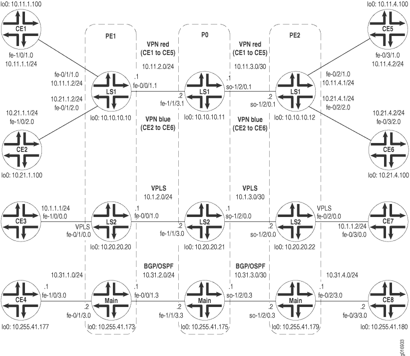
ルーター PE1 では、論理システム LS1 に 2 つの VPN ルーティングおよび転送(VRF)ルーティング インスタンスが作成されます。ルーティング インスタンスは赤と青と呼ばれます。この例では、ルーターCE1からのトラフィックが赤いVPNに配置され、ルーターCE2からのトラフィックが青いVPNに配置されるように、カスタマーエッジ(CE)側の論理インターフェイスを設定します。 fe-0/0/1.1 の論理インターフェイスは、ルーター P0 の論理システム LS1 に接続します。VPLS ルーティング インスタンスは論理システム LS2 にあります。論理インターフェイスは、ルーター CE3 からのトラフィックが VPLS ドメインに送信されるように設定されています。この論理インターフェイスは、ルーター P0 の論理システム LS2 に接続します。この例には、論理システム LS1 の管理者も含まれています。論理システム管理者は、この論理システムの保守を担当します。最後に、この例では、ルーター PE1 のメイン ルーター部分とルーター CE4 を相互接続するように論理インターフェイスを設定する方法を示しています。
ルーター PE2 には、論理システム LS1 に 2 つの VRF ルーティング インスタンス(赤と青)があります。CE側の論理インターフェイスにより、ルーターCE5からのトラフィックを赤いVPNに、ルーターCE6からのトラフィックを青いVPNに配置できます。 so-1/2/0.1 上の 1 つの論理インターフェイスが、ルーター P0 の論理システム LS1 に接続されます。VPLS ルーティング インスタンスは論理システム LS2 で設定されます。論理インターフェイスにより、ルーター CE7 からのトラフィックを VPLS ドメインに送信し、ルーター P0 の論理システム LS2 に接続できます。この例では、ルーター CE8 をルーター P0 のメイン ルーター部分と相互接続するように論理インターフェイスを設定する方法を示しています。最後に、論理システム LS1 の設定権限と論理システム LS2 の表示権限を持つ論理システム管理者を必要に応じて作成できます。
ルーター P0 では、論理システム LS1、LS2、メイン ルーターを設定する方法を例に示します。物理インターフェイス のプロパティは、メイン ルーター [edit interfaces] 階層レベルで設定する必要があります。次に、プロトコル(RSVP、MPLS、BGP、IS-IS など)、ルーティング オプション、論理システムのポリシー オプションを設定する方法を示します。最後に、この例では、ルーター PE1 で設定されている論理システム LS1 に同じ管理者を設定する方法を示しています。論理システム LS2 のこのシステム管理者は、LS2 設定を表示する権限を持っていますが、論理システム LS2 の設定は変更できません。
論理システム LS1 は、ルーター CE1 と CE5 の間に存在する red VPN のトラフィックを転送します。論理システム LS1 は、ルーター CE2 と CE6 の間に存在する blue VPN も接続します。論理システム LS2 は、ルーター CE3 と CE7 間で VPLS トラフィックを転送します。ルーター P0 のメイン ルーターでは、通常どおりにルーターを設定できます。メイン ルーターは、ルーター CE4 と CE8 間のトラフィックを転送します。この例では、ルーター PE1 および PE2 のメイン ルーター部分に接続するようにインターフェイスとルーティング プロトコル(OSPF、BGP)を設定する方法を示しています。
構成
論理システムで PE ルーターと P ルーターを構成するには、以下のタスクを実行する必要があります。
カスタマー エッジ デバイスでのインターフェイスの設定
手順
次の例では、設定階層のさまざまなレベルに移動する必要があります。CLI のナビゲーションの詳細については、『CLI ユーザー ガイド』の「設定モードでの CLI エディターの使用」を参照してください。
ルーター CE1 で、ルーター PE1 の論理システム LS1 の red VPN に接続するように OSPF を設定します。
user@CE1# set interfaces fe-1/0/1 vlan-tagging
user@CE1# set interfaces fe-1/0/1 unit 0 description "routing-instance red CE"
user@CE1# set interfaces fe-1/0/1 unit 0 vlan-id 101
user@CE1# set interfaces fe-1/0/1 unit 0 family inet address 10.11.1.1/24
user@CE1# set interfaces lo0 unit 0 family inet address 10.11.1.100/32
user@CE1# set protocols ospf area 0.0.0.0 interface fe-1/0/1.0
user@CE1# set protocols ospf area 0.0.0.0 interface lo0.0
ルーター CE2 で、ルーター PE1 の論理システム LS1 の blue VPN に接続するように BGP を設定します。
user@CE2# set interfaces fe-1/0/2 vlan-tagging
user@CE2# set interfaces fe-1/0/2 unit 0 description "routing-instance blue CE"
user@CE2# set interfaces fe-1/0/2 unit 0 vlan-id 102
user@CE2# set interfaces fe-1/0/2 unit 0 family inet address 10.21.1.1/24
user@CE2# set interfaces lo0 unit 0 family inet address 10.21.1.100/32
user@CE2# set policy-options policy-statement export_loopback from route-filter 10.21.1.100/32 exact
user@CE2# set policy-options policy-statement export_loopback then accept
user@CE2# set protocols bgp export export_loopback
user@CE2# set protocols bgp group to_PE type external
user@CE2# set protocols bgp group to_PE local-address 10.21.1.1
user@CE2# set protocols bgp group to_PE peer-as 100
user@CE2# set protocols bgp group to_PE neighbor 10.21.1.2
user@CE2# set routing-options autonomous-system 200
ルーター CE3 では、VLAN 600 のファスト イーサネット インターフェイスを設定し、ルーター PE1 の論理システム LS2 の VPLS ルーティング インスタンスと接続します。
user@CE3# set interfaces fe-1/0/0 vlan-tagging
user@CE3# set interfaces fe-1/0/0 unit 0 description "vpls interface"
user@CE3# set interfaces fe-1/0/0 unit 0 vlan-id 600
user@CE3# set interfaces fe-1/0/0 unit 0 family inet address 10.1.1.1/24
ルーター CE4 で、ルーター PE1 のメイン ルーターと接続するようにファスト イーサネット インターフェイスを設定します。
user@CE4# set interfaces fe-1/0/3 vlan-tagging
user@CE4# set interfaces fe-1/0/3 unit 0 description "main router interface"
user@CE4# set interfaces fe-1/0/3 unit 0 vlan-id 103
user@CE4# set interfaces fe-1/0/3 unit 0 family inet address 10.31.1.1/24
user@CE4# set interfaces lo0 unit 0 family inet address 10.255.41.177/32
ルーター CE5 で、ルーター PE2 の論理システム LS1 の red VPN に接続するように OSPF を設定します。
user@CE5# set interfaces fe-0/3/1 vlan-tagging
user@CE5# set interfaces fe-0/3/1 unit 0 description "routing-instance red CE"
user@CE5# set interfaces fe-0/3/1 unit 0 vlan-id 101
user@CE5# set interfaces fe-0/3/1 unit 0 family inet address 10.11.4.2/24
user@CE5# set interfaces lo0 unit 0 family inet address 10.11.4.100/32
user@CE5# set protocols ospf area 0.0.0.0 interface fe-0/3/1.0
user@CE5# set protocols ospf area 0.0.0.0 interface lo0.0
user@CE5# set system login class LS1admin logical-system LS1
user@CE5# set system login class LS1admin permissions all
user@CE5# set system login class LS1onlooker logical-system LS2
user@CE5# set system login class LS1onlooker permissions view
user@CE5# set system login user LS1admin class LS1admin
ルーター CE6 で、ルーター PE2 の論理システム LS1 の blue VPN に接続するように BGP を設定します。
user@CE6# set interfaces fe-0/3/2 vlan-tagging
user@CE6# set interfaces fe-0/3/2 unit 0 description "routing-instance blue CE"
user@CE6# set interfaces fe-0/3/2 unit 0 vlan-id 102
user@CE6# set interfaces fe-0/3/2 unit 0 family inet address 10.21.4.2/24
user@CE6# set interfaces lo0 unit 0 family inet address 10.21.4.100/32
user@CE6# set routing-options autonomous-system 300
user@CE6# set protocols bgp export export_loopback
user@CE6# set protocols bgp group to_PE type external
user@CE6# set protocols bgp group to_PE local-address 10.21.4.2
user@CE6# set protocols bgp group to_PE peer-as 100
user@CE6# set protocols bgp group to_PE neighbor 10.21.4.1
user@CE6# set policy-options policy-statement export_loopback from route-filter 10.21.4.100/32 exact
user@CE6# set policy-options policy-statement export_loopback then accept
ルーター CE7 では、VLAN 600 のファスト イーサネット インターフェイスを設定し、ルーター PE2 の論理システム LS2 の VPLS ルーティング インスタンスと接続します。
user@CE7# set interfaces fe-0/3/0 vlan-tagging
user@CE7# set interfaces fe-0/3/0 unit 0 description "vpls interface"
user@CE7# set interfaces fe-0/3/0 unit 0 vlan-id 600
user@CE7# set interfaces fe-0/3/0 unit 0 family inet address 10.1.1.2/24
ルーター CE8 で、ルーター PE2 のメイン ルーターと接続するようにファスト イーサネット インターフェイスを設定します。
user@CE8# set interfaces fe-0/3/3 vlan-tagging
user@CE8# set interfaces fe-0/3/3 unit 0 description "main router interface"
user@CE8# set interfaces fe-0/3/3 unit 0 vlan-id 103
user@CE8# set interfaces fe-0/3/3 unit 0 family inet address 10.31.4.2/24
user@CE8# set interfaces lo0 unit 0 family inet address 10.255.41.180/32
ルーター PE1 の設定
手順
ルーター PE1 でメイン ルーターを設定します。
user@PE1# set interfaces fe-0/0/1 vlan-tagging
user@PE1# set interfaces fe-0/0/1 unit 3 description "main router to P0"
user@PE1# set interfaces fe-0/0/1 unit 3 vlan-id 103
user@PE1# set interfaces fe-0/0/1 unit 3 family inet address 10.31.2.1/24
user@PE1# set interfaces fe-0/0/1 unit 3 family iso
user@PE1# set interfaces fe-0/0/1 unit 3 family mpls
user@PE1# set interfaces fe-0/1/0 vlan-tagging
user@PE1# set interfaces fe-0/1/0 encapsulation vlan-vpls
user@PE1# set interfaces fe-0/1/1 vlan-tagging
user@PE1# set interfaces fe-0/1/2 vlan-tagging
user@PE1# set interfaces fe-0/1/3 vlan-tagging
user@PE1# set interfaces fe-0/1/3 unit 0 description "main router to CE4"
user@PE1# set interfaces fe-0/1/3 unit 0 vlan-id 103
user@PE1# set interfaces fe-0/1/3 unit 0 family inet address 10.31.1.2/24
user@PE1# set interfaces lo0 unit 0 description "main router loopback"
user@PE1# set interfaces lo0 unit 0 family inet address 10.255.41.173/32
user@PE1# set protocols bgp group to_main_ls type internal
user@PE1# set protocols bgp group to_main_ls local-address 10.255.41.173
user@PE1# set protocols bgp group to_main_ls export export_address
user@PE1# set protocols bgp group to_main_ls neighbor 10.255.41.179
user@PE1# set protocols bgp group to_main_ls neighbor 10.255.41.175
user@PE1# set protocols ospf area 0.0.0.0 interface lo0.0
user@PE1# set protocols ospf area 0.0.0.0 interface fe-0/0/1.3
user@PE1# set routing-options static route 10.255.41.177/32 next-hop 10.31.1.1
user@PE1# set routing-options autonomous-system 500
user@PE1# set policy-options policy-statement export_address from route-filter 10.255.41.177/32 exact
user@PE1# set policy-options policy-statement export_address then accept
user@PE1# set system login class LS1-admin logical-system LS1
user@PE1# set system login class LS1-admin permissions all
user@PE1# set system login user LS1-admin class LS1-admin
user@PE1# set system login user LS1-admin authentication plain-text-password
New password:
Retype new password:
ルーター PE1 で論理システム LS1 を設定します。
user@PE1# set logical-systems LS1 interfaces fe-0/0/1 unit 1 description "LS1 interface"
user@PE1# set logical-systems LS1 interfaces fe-0/0/1 unit 1 vlan-id 101
user@PE1# set logical-systems LS1 interfaces fe-0/0/1 unit 1 family inet address 10.11.2.1/24
user@PE1# set logical-systems LS1 interfaces fe-0/0/1 unit 1 family iso
user@PE1# set logical-systems LS1 interfaces fe-0/0/1 unit 1 family mpls
user@PE1# set logical-systems LS1 interfaces fe-0/1/1 unit 0 description "routing-instance red interface"
user@PE1# set logical-systems LS1 interfaces fe-0/1/1 unit 0 vlan-id 101
user@PE1# set logical-systems LS1 interfaces fe-0/1/1 unit 0 family inet address 10.11.1.2/24
user@PE1# set logical-systems LS1 interfaces fe-0/1/2 unit 0 description "routing-instance blue interface"
user@PE1# set logical-systems LS1 interfaces fe-0/1/2 unit 0 vlan-id 102
user@PE1# set logical-systems LS1 interfaces fe-0/1/2 unit 0 family inet address 10.21.1.2/24
user@PE1# set logical-systems LS1 interfaces lo0 unit 1 description "LS1 loopback"
user@PE1# set logical-systems LS1 interfaces lo0 unit 1 family inet address 10.10.10.10/32
user@PE1# set logical-systems LS1 interfaces lo0 unit 1 family iso address 47.1111.1111.1111.1111.00
user@PE1# set logical-systems LS1 protocols rsvp interface all
user@PE1# set logical-systems LS1 protocols mpls label-switched-path to_10.10.10.12 to 10.10.10.12
user@PE1# set logical-systems LS1 protocols mpls interface all
user@PE1# set logical-systems LS1 protocols bgp group to_other_PE type internal
user@PE1# set logical-systems LS1 protocols bgp group to_other_PE local-address 10.10.10.10
user@PE1# set logical-systems LS1 protocols bgp group to_other_PE family inet-vpn any
user@PE1# set logical-systems LS1 protocols bgp group to_other_PE neighbor 10.10.10.12
user@PE1# set logical-systems LS1 protocols isis interface all
user@PE1# set logical-systems LS1 policy-options policy-statement from_bgp_to_ospf then accept
user@PE1# set logical-systems LS1 routing-instances blue instance-type vrf
user@PE1# set logical-systems LS1 routing-instances blue interface fe-0/1/2.0
user@PE1# set logical-systems LS1 routing-instances blue route-distinguisher 10.10.10.10:200
user@PE1# set logical-systems LS1 routing-instances blue vrf-target target:20:20
user@PE1# set logical-systems LS1 routing-instances blue protocols bgp group to_CE type external
user@PE1# set logical-systems LS1 routing-instances blue protocols bgp group to_CE local-address 10.21.1.2
user@PE1# set logical-systems LS1 routing-instances blue protocols bgp group to_CE peer-as 200
user@PE1# set logical-systems LS1 routing-instances blue protocols bgp group to_CE neighbor 10.21.1.1
user@PE1# set logical-systems LS1 routing-instances red instance-type vrf
user@PE1# set logical-systems LS1 routing-instances red interface fe-0/1/1.0
user@PE1# set logical-systems LS1 routing-instances red route-distinguisher 10.10.10.10:100
user@PE1# set logical-systems LS1 routing-instances red vrf-target target:10:10
user@PE1# set logical-systems LS1 routing-instances red protocols ospf export from_bgp_to_ospf
user@PE1# set logical-systems LS1 routing-instances red protocols ospf area 0.0.0.0 interface all
user@PE1# set logical-systems LS1 routing-options autonomous-system 100
ルーター PE1 で論理システム LS2 を設定します。
user@PE1# set logical-systems LS2 interfaces fe-0/0/1 unit 0 description "core-facing LS2 interface"
user@PE1# set logical-systems LS2 interfaces fe-0/0/1 unit 0 vlan-id 100
user@PE1# set logical-systems LS2 interfaces fe-0/0/1 unit 0 family inet address 10.1.2.1/24
user@PE1# set logical-systems LS2 interfaces fe-0/0/1 unit 0 family iso
user@PE1# set logical-systems LS2 interfaces fe-0/0/1 unit 0 family mpls
user@PE1# set logical-systems LS2 interfaces fe-0/1/0 unit 0 description "vpls interface to ce3"
user@PE1# set logical-systems LS2 interfaces fe-0/1/0 unit 0 encapsulation vlan-vpls
user@PE1# set logical-systems LS2 interfaces fe-0/1/0 unit 0 vlan-id 600
user@PE1# set logical-systems LS2 interfaces fe-0/1/0 unit 0 family vpls
user@PE1# set logical-systems LS2 interfaces lo0 unit 2 description "LS2 loopback"
user@PE1# set logical-systems LS2 interfaces lo0 unit 2 family inet address 10.20.20.20/32
user@PE1# set logical-systems LS2 interfaces lo0 unit 2 family iso address 47.2222.2222.2222.2222.00
user@PE1# set logical-systems LS2 protocols rsvp interface all
user@PE1# set logical-systems LS2 protocols mpls label-switched-path to_10.20.20.22 to 10.20.20.22
user@PE1# set logical-systems LS2 protocols mpls interface all
user@PE1# set logical-systems LS2 protocols bgp group to_VPLS_PE type internal
user@PE1# set logical-systems LS2 protocols bgp group to_VPLS_PE local-address 10.20.20.20
user@PE1# set logical-systems LS2 protocols bgp group to_VPLS_PE family l2vpn signaling
user@PE1# set logical-systems LS2 protocols bgp group to_VPLS_PE neighbor 10.20.20.22
user@PE1# set logical-systems LS2 protocols isis interface fe-0/0/1.0
user@PE1# set logical-systems LS2 protocols isis interface lo0.2
user@PE1# set logical-systems LS2 routing-instances new instance-type vpls
user@PE1# set logical-systems LS2 routing-instances new interface fe-0/1/0.0
user@PE1# set logical-systems LS2 routing-instances new route-distinguisher 10.20.20.20:100
user@PE1# set logical-systems LS2 routing-instances new vrf-target target:30:30
user@PE1# set logical-systems LS2 routing-instances new protocols vpls site-range 10
user@PE1# set logical-systems LS2 routing-instances new protocols vpls site newPE site-identifier 1
user@PE1# set logical-systems LS2 routing-options autonomous-system 400
ルーター PE2 の設定
手順
ルーター PE2 でメイン ルーターを設定します。
user@PE2# set interfaces fe-0/2/0 vlan-tagging
user@PE2# set interfaces fe-0/2/0 encapsulation vlan-vpls
user@PE2# set interfaces fe-0/2/1 vlan-tagging
user@PE2# set interfaces fe-0/2/2 vlan-tagging
user@PE2# set interfaces fe-0/2/3 vlan-tagging
user@PE2# set interfaces fe-0/2/3 unit 0 description "main router to CE8"
user@PE2# set interfaces fe-0/2/3 unit 0 vlan-id 103
user@PE2# set interfaces fe-0/2/3 unit 0 family inet address 10.31.4.1/24
user@PE2# set interfaces so-1/2/0 encapsulation frame-relay
user@PE2# set interfaces so-1/2/0 unit 3 description "main router to P0"
user@PE2# set interfaces so-1/2/0 unit 3 dlci 103
user@PE2# set interfaces so-1/2/0 unit 3 family inet address 10.31.3.2/24
user@PE2# set interfaces so-1/2/0 unit 3 family iso
user@PE2# set interfaces so-1/2/0 unit 3 family mpls
user@PE2# set interfaces lo0 unit 0 description "main router loopback"
user@PE2# set interfaces lo0 unit 0 family inet address 10.155.41.179/32
user@PE2# set protocols bgp group to_main_ls type internal
user@PE2# set protocols bgp group to_main_ls local-address 10.255.41.179
user@PE2# set protocols bgp group to_main_ls export export_address
user@PE2# set protocols bgp group to_main_ls neighbor 10.255.41.173
user@PE2# set protocols bgp group to_main_ls neighbor 10.255.41.175
user@PE2# set protocols ospf area 0.0.0.0 interface so-1/2/0.3
user@PE2# set protocols ospf area 0.0.0.0 interface fe-0/2/3.0
user@PE2# set protocols ospf area 0.0.0.0 interface lo0.0
user@PE2# set routing-options static route 10.255.41.180/32 next-hop 10.31.4.2
user@PE2# set routing-options autonomous-system 500
user@PE2# set policy-options policy-statement export_address from route-filter 10.255.41.180/32 exact
user@PE2# set policy-options policy-statement export_address then accept
user@PE2# set system login class LS1-admin logical-system LS1
user@PE2# set system login class LS1-admin permissions all
user@PE2# set system login class LS1-onlooker logical-system LS2
user@PE2# set system login class LS1-onlooker permissions view
user@PE2# set system login user LS1-admin class LS1-admin
ルーター PE2 で論理システム LS1 を設定します。
user@PE2# set logical-systems LS1 interfaces fe-0/2/0 unit 1 description "routing-instance red interface connects to Router CE5"
user@PE2# set logical-systems LS1 interfaces fe-0/2/0 unit 1 vlan-id 101
user@PE2# set logical-systems LS1 interfaces fe-0/2/0 unit 1 family inet address 10.11.4.1/24
user@PE2# set logical-systems LS1 interfaces fe-0/2/0 unit 2 description "routing-instance blue interface connects to Router CE6"
user@PE2# set logical-systems LS1 interfaces fe-0/2/0 unit 2 vlan-id 102
user@PE2# set logical-systems LS1 interfaces fe-0/2/0 unit 2 family inet address 10.21.4.1/24
user@PE2# set logical-systems LS1 interfaces so-1/2/0 unit 1 description "core-facing LS1 interface"
user@PE2# set logical-systems LS1 interfaces so-1/2/0 unit 1 dlci 101
user@PE2# set logical-systems LS1 interfaces so-1/2/0 unit 1 family inet address 10.11.3.2/24
user@PE2# set logical-systems LS1 interfaces so-1/2/0 unit 1 family iso
user@PE2# set logical-systems LS1 interfaces so-1/2/0 unit 1 family mpls
user@PE2# set logical-systems LS1 interfaces lo0 unit 1 description "LS1 loopback"
user@PE2# set logical-systems LS1 interfaces lo0 unit 1 family inet address 10.10.10.12/32
user@PE2# set logical-systems LS1 interfaces lo0 unit 1 family iso address 47.1111.1111.1111.1113.00
user@PE2# set logical-systems LS1 protocols rsvp interface all
user@PE2# set logical-systems LS1 protocols mpls label-switched-path to_10.10.10.10 to 10.10.10.10
user@PE2# set logical-systems LS1 protocols mpls interface all
user@PE2# set logical-systems LS1 protocols bgp group to_other_PE type internal
user@PE2# set logical-systems LS1 protocols bgp group to_other_PE local-address 10.10.10.12
user@PE2# set logical-systems LS1 protocols bgp group to_other_PE family inet any
user@PE2# set logical-systems LS1 protocols bgp group to_other_PE family inet-vpn any
user@PE2# set logical-systems LS1 protocols bgp group to_other_PE neighbor 10.10.10.10
user@PE2# set logical-systems LS1 protocols isis interface all
user@PE2# set logical-systems LS1 policy-options policy-statement from_bgp_to_ospf then accept
user@PE2# set logical-systems LS1 routing-instances blue instance-type vrf
user@PE2# set logical-systems LS1 routing-instances blue interface fe-0/2/2.0
user@PE2# set logical-systems LS1 routing-instances blue route-distinguisher 10.10.10.12:200
user@PE2# set logical-systems LS1 routing-instances blue vrf-target target:20:20
user@PE2# set logical-systems LS1 routing-instances blue protocols bgp group to_CE local-address 10.21.4.1
user@PE2# set logical-systems LS1 routing-instances blue protocols bgp group to_CE peer-as 300
user@PE2# set logical-systems LS1 routing-instances blue protocols bgp group to_CE neighbor 10.21.4.2
user@PE2# set logical-systems LS1 routing-instances red instance-type vrf
user@PE2# set logical-systems LS1 routing-instances red interface fe-0/2/1.0
user@PE2# set logical-systems LS1 routing-instances red route-distinguisher 10.10.10.12:100
user@PE2# set logical-systems LS1 routing-instances red vrf-target target:10:10
user@PE2# set logical-systems LS1 routing-instances red protocols ospf export from_bgp_to_ospf
user@PE2# set logical-systems LS1 routing-instances red protocols ospf area 0.0.0.0 interface all
user@PE2# set logical-systems LS1 routing-options autonomous-system 100
ルーター PE2 で論理システム LS2 を設定します。
user@PE2# set logical-systems LS2 interfaces fe-0/2/0 unit 0 description "vpls interface connects to Router CE7"
user@PE2# set logical-systems LS2 interfaces fe-0/2/0 unit 0 encapsulation vlan-vpls
user@PE2# set logical-systems LS2 interfaces fe-0/2/0 unit 0 vlan-id 600
user@PE2# set logical-systems LS2 interfaces fe-0/2/0 unit 0 family vpls
user@PE2# set logical-systems LS2 interfaces so-1/2/0 unit 0 description "core-facing LS2 interface"
user@PE2# set logical-systems LS2 interfaces so-1/2/0 unit 0 dlci 100
user@PE2# set logical-systems LS2 interfaces so-1/2/0 unit 0 family inet address 10.1.3.2/24
user@PE2# set logical-systems LS2 interfaces so-1/2/0 unit 0 family iso
user@PE2# set logical-systems LS2 interfaces so-1/2/0 unit 0 family mpls
user@PE2# set logical-systems LS2 interfaces lo0 unit 2 description "LS2 loopback"
user@PE2# set logical-systems LS2 interfaces lo0 unit 2 family inet address 10.20.20.22/32
user@PE2# set logical-systems LS2 interfaces lo0 unit 2 family iso address 47.2222.2222.2222.2224.00
user@PE2# set logical-systems LS2 protocols rsvp interface all
user@PE2# set logical-systems LS2 protocols mpls label-switched-path to_10.20.20.20 to 10.20.20.20
user@PE2# set logical-systems LS2 protocols mpls interface all
user@PE2# set logical-systems LS2 protocols bgp group to_VPLS_PE type internal
user@PE2# set logical-systems LS2 protocols bgp group to_VPLS_PE local-address 10.20.20.22
user@PE2# set logical-systems LS2 protocols bgp group to_VPLS_PE family l2vpn signaling
user@PE2# set logical-systems LS2 protocols bgp group to_VPLS_PE neighbor 10.20.20.20
user@PE2# set logical-systems LS2 protocols isis interface so-1/2/0.0
user@PE2# set logical-systems LS2 protocols isis interface lo0.2
user@PE2# set logical-systems LS2 routing-instances new instance-type vpls
user@PE2# set logical-systems LS2 routing-instances new interface fe-0/2/0.0
user@PE2# set logical-systems LS2 routing-instances new route-distinguisher 10.20.20.22:100
user@PE2# set logical-systems LS2 routing-instances new vrf-target target:30:30
user@PE2# set logical-systems LS2 routing-instances new protocols vpls site-range 10
user@PE2# set logical-systems LS2 routing-instances new protocols vpls site newPE site-identifier 2
user@PE2# set logical-systems LS2 routing-options autonomous-system 400
ルーター P0 の設定
手順
ルーター P0 でメイン ルーターを設定します。
user@P0# set interfaces fe-1/1/3 vlan-tagging
user@P0# set interfaces fe-1/1/3 unit 3 description "connects to the main router on pe1"
user@P0# set interfaces fe-1/1/3 unit 3 vlan-id 103
user@P0# set interfaces fe-1/1/3 unit 3 family inet address 10.31.2.2/24
user@P0# set interfaces fe-1/1/3 unit 3 family iso
user@P0# set interfaces fe-1/1/3 unit 3 family mpls
user@P0# set interfaces so-1/2/0 dce
user@P0# set interfaces so-1/2/0 encapsulation frame-relay
user@P0# set interfaces so-1/2/0 unit 3 description "connects to the main router on pe2"
user@P0# set interfaces so-1/2/0 unit 3 dlci 103
user@P0# set interfaces so-1/2/0 unit 3 family inet address 10.31.3.1/24
user@P0# set interfaces so-1/2/0 unit 3 family iso
user@P0# set interfaces so-1/2/0 unit 3 family mpls
user@P0# set interfaces lo0 unit 0 description "main router loopback"
user@P0# set interfaces lo0 unit 0 family inet address 10.255.41.175/32
user@P0# set routing-options autonomous-system 500
user@P0# set protocols bgp group to_main_ls type internal
user@P0# set protocols bgp group to_main_ls local-address 10.255.41.175
user@P0# set protocols bgp group to_main_ls neighbor 10.255.41.179
user@P0# set protocols bgp group to_main_ls neighbor 10.255.41.173
user@P0# set protocols ospf area 0.0.0.0 interface lo0.0
user@P0# set protocols ospf area 0.0.0.0 interface fe-1/1/3.3
user@P0# set protocols ospf area 0.0.0.0 interface so-1/2/0.3
user@P0# set system login class LS1-admin logical-system LS1
user@P0# set system login class LS1-admin permissions all
user@P0# set system login class LS1-onlooker logical-system LS2
user@P0# set system login class LS1-onlooker permissions view
user@P0# set system login user LS1-admin class LS1-admin
ルーター P0 で論理システム LS1 を設定します。
user@P0# set logical-systems LS1 interfaces fe-1/1/3 unit 1 description "LS1 interface connects to LS1 on pe1"
user@P0# set logical-systems LS1 interfaces fe-1/1/3 unit 1 vlan-id 101
user@P0# set logical-systems LS1 interfaces fe-1/1/3 unit 1 family inet address 10.11.2.2/24
user@P0# set logical-systems LS1 interfaces fe-1/1/3 unit 1 family iso
user@P0# set logical-systems LS1 interfaces fe-1/1/3 unit 1 family mpls
user@P0# set logical-systems LS1 interfaces so-1/2/0 unit 1 description "LS1 interface connects to LS1 on pe2"
user@P0# set logical-systems LS1 interfaces so-1/2/0 unit 1 dlci 101
user@P0# set logical-systems LS1 interfaces so-1/2/0 unit 1 family inet address 10.11.3.1/24
user@P0# set logical-systems LS1 interfaces so-1/2/0 unit 1 family iso
user@P0# set logical-systems LS1 interfaces so-1/2/0 unit 1 family mpls
user@P0# set logical-systems LS1 interfaces lo0 unit 1 description "LS1 loopback"
user@P0# set logical-systems LS1 interfaces lo0 unit 1 family inet address 10.10.10.11/32
user@P0# set logical-systems LS1 interfaces lo0 unit 1 family iso address 47.1111.1111.1111.1112.00
user@P0# set logical-systems LS1 protocols rsvp interface all
user@P0# set logical-systems LS1 protocols mpls interface all
user@P0# set logical-systems LS1 protocols isis interface all
ルーター P0 で論理システム LS2 を設定します。
user@P0# set logical-systems LS2 interfaces fe-1/1/3 unit 0 description "LS2 interface connects to LS2 on pe1"
user@P0# set logical-systems LS2 interfaces fe-1/1/3 unit 0 vlan-id 100
user@P0# set logical-systems LS2 interfaces fe-1/1/3 unit 0 family inet address 10.1.2.2/24
user@P0# set logical-systems LS2 interfaces fe-1/1/3 unit 0 family iso
user@P0# set logical-systems LS2 interfaces fe-1/1/3 unit 0 family mpls
user@P0# set logical-systems LS2 interfaces so-1/2/0 unit 0 description "LS2 interface connects to LS2 on pe2"
user@P0# set logical-systems LS2 interfaces so-1/2/0 unit 0 dlci 100
user@P0# set logical-systems LS2 interfaces so-1/2/0 unit 0 family inet address 10.1.3.1/24
user@P0# set logical-systems LS2 interfaces so-1/2/0 unit 0 family iso
user@P0# set logical-systems LS2 interfaces so-1/2/0 unit 0 family mpls
user@P0# set logical-systems LS2 interfaces lo0 unit 2 description "LS2 loopback"
user@P0# set logical-systems LS2 interfaces lo0 unit 2 family inet address 10.20.20.21/32
user@P0# set logical-systems LS2 interfaces lo0 unit 2 family iso address 47.2222.2222.2222.2223.00
user@P0# set logical-systems LS2 protocols rsvp interface all
user@P0# set logical-systems LS2 protocols mpls interface all
user@P0# set logical-systems LS2 protocols isis interface fe-1/1/3.0
user@P0# set logical-systems LS2 protocols isis interface so-1/2/0.0
user@P0# set logical-systems LS2 protocols isis interface lo0.2
結果
ルーター CE1 で、ルーター PE1 の論理システム LS1 の red VPN に接続するように OSPF を設定します。
ルーター CE1
[edit]
interfaces {
    fe-1/0/1 {
        vlan-tagging;
        unit 0 {
            description "routing-instance red CE";
            vlan-id 101;
            family inet {
                address 10.11.1.1/24;
            }
        }
    }
    lo0 {
        unit 0 {
            family inet {
                address 10.11.1.100/32;
            }
        }
    }
}
protocols {
    ospf {
        area 0.0.0.0 {
            interface fe-1/0/1.0;
            interface lo0.0;
        }
    }
}
ルーター CE2 で、ルーター PE1 の論理システム LS1 の blue VPN に接続するように BGP を設定します。
ルーター CE2
[edit]
interfaces {
    fe-1/0/2 {
        vlan-tagging;
        unit 0 {
            description "routing-instance blue CE";
            vlan-id 102;
            family inet {
                address 10.21.1.1/24;
            }
        }
    }
    lo0 {
        unit 0 {
            family inet {
                address 10.21.1.100/32;
            }
        }
    }
}
routing-options {
    autonomous-system 200;
}
protocols {
    bgp {
        export export_loopback;
        group to_PE {
            type external;
            local-address 10.21.1.1;
            peer-as 100;
            neighbor 10.21.1.2;
        }
    }
}
policy-options {
    policy-statement export_loopback {
        from {
            route-filter 10.21.1.100/32 exact;
        }
        then accept;
    }
}
ルーター CE3 で、VLAN 600 のファスト イーサネット インターフェイスを設定し、ルーター PE1 の論理システム LS2 の VPLS ルーティング インスタンスと接続します。
ルーター CE3
[edit]
interfaces {
    fe-1/0/0 {
        vlan-tagging;
        unit 0 {
            description "vpls interface";
            vlan-id 600;
            family inet {
                address 10.1.1.1/24;
            }
        }
    }
}
ルーター CE4 で、ルーター PE1 のメイン ルーターと接続するようにファスト イーサネット インターフェイスを設定します。
ルーター CE4
[edit]
interfaces {
    fe-1/0/3 {
        vlan-tagging;
        unit 0 {
            description "main router interface";
            vlan-id 103;
            family inet {
                address 10.31.1.1/24;
            }
        }
    }
    lo0 {
        unit 0 {
            family inet {
                address 10.255.41.177/32;
            }
        }
    }
}
ルーター PE1 で、論理システム LS1 で 2 つの VPN ルーティングおよび転送(VRF)ルーティング インスタンスを作成します。赤と青。ルーターCE1からのトラフィックが赤いVPNに配置され、ルーターCE2 からのトラフィックが青いVPNに配置されるように、CE側の論理インターフェイスを設定します。次に、 fe-0/0/1.1 で論理インターフェイスを作成し、ルーター P0 の論理システム LS1 に接続します。
ルーター PE1 でも、論理システム LS2 に VPLS ルーティング インスタンスを作成します。ルーター CE3 からのトラフィックが VPLS ドメインに送信され、ルーター P0 の論理システム LS2 に接続されるように、論理インターフェイスを設定します。
論理システム LS1 の管理者を作成します。論理システム管理者は、この論理システムの保守を担当することができます。
最後に、ルーター CE4 をルーター P0 のメイン ルーター部分と相互接続するように論理インターフェイスを設定します 。
ルーター PE1
[edit]
logical-systems {
    LS1 { # The configuration for the first logical system begins here.
        interfaces {
            fe-0/0/1 {
                unit 1 {  # This is the core-facing interface for Logical System LS1.
                    description "LS1 interface";
                    vlan-id 101;
                    family inet {
                        address 10.11.2.1/24;
                    }
                    family iso;
                    family mpls;
                }
            }
            fe-0/1/1 {
                unit 0 {   # This logical interface connects to Router CE1.
                    description "routing-instance red interface";
                    vlan-id 101;
                    family inet {
                        address 10.11.1.2/24;
                    }
                }
            }
            fe-0/1/2 {
                unit 0 {   # This logical interface connects to Router CE2.
                    description "routing-instance blue interface";
                    vlan-id 102;
                    family inet {
                        address 10.21.1.2/24;
                    }
                }
            }
            lo0 {
                unit 1 {
                    description "LS1 loopback";
                    family inet {
                        address 10.10.10.10/32;
                    }
                    family iso {
                        address 47.1111.1111.1111.1111.00;
                    }
                }
            }
        }
         protocols { # You configure RSVP, MPLS, IS-IS, and BGP for Logical System LS1.
            rsvp  {
                interface all;
            }
            mpls    {
                label-switched-path to_10.10.10.12 {
                    to 10.10.10.12;
                }
                interface all;
            }
             bgp {
                group to_other_PE {
                    type internal;
                    local-address 10.10.10.10;
                    family inet-vpn {
                        any;
                    }
                    neighbor 10.10.10.12;
                }
            }
            isis {
                interface all;
            }
        }
        policy-options {
            policy-statement from_bgp_to_ospf {
                then accept;
            }
        }
        routing-instances {
            blue {
                instance-type vrf; # You configure instance blue within Logical System LS1.
                interface fe-0/1/2.0;
                route-distinguisher 10.10.10.10:200;
                vrf-target target:20:20;
                protocols {
                    bgp {   #BGP connects the blue instance with Router CE2.
                        group to_CE {
                            type external;
                            local-address 10.21.1.2;
                            peer-as 200;
                            neighbor 10.21.1.1;
                        }
                    }
                }
            }
            red {
                 instance-type vrf; # You configure instance red within Logical System LS1.
                interface fe-0/1/1.0;
                route-distinguisher 10.10.10.10:100;
                vrf-target target:10:10;
                protocols {
                    ospf {#OSPF connects the red instance with Router CE1.
                        export from_bgp_to_ospf;
                        area 0.0.0.0 {
                            interface all;
                        }
                    }
                }
            }
        }
        routing-options {
            autonomous-system 100;
        }
    }
    LS2 {  # The configuration for the second logical system begins here.
        interfaces {
            fe-0/0/1 {
                unit 0 {  # This is the core-facing interface for Logical System LS2.
                    description "LS2 interface";
                    vlan-id 100;
                    family inet {
                        address 10.1.2.1/24;
                    }
                    family iso;
                    family mpls;
                }
            }
            fe-0/1/0 {
                 unit 0 {  # This logical interface connects to Router CE3.
                    description "vpls interface";
                    encapsulation vlan-vpls;
                    vlan-id 600;
                    family vpls;
                }
            }
            lo0 {
                unit 2 {
                    description "LS2 loopback";
                    family inet {
                        address 10.20.20.20/32;
                    }
                    family iso {
                        address 47.2222.2222.2222.2222.00;
                    }
                }
            }
        }
        protocols { # You configure RSVP, MPLS, IS-IS, and BGP for Logical System LS2.
             rsvp {
                interface all;
            }
             mpls {
                label-switched-path to_10.20.20.22 {
                    to 10.20.20.22;
                }
                interface all;
            }
            bgp {
                group to_VPLS_PE {
                    type internal;
                    local-address 10.20.20.20;
                    family l2vpn {
                        signaling;
                    }
                    neighbor 10.20.20.22;
                }
            }
            isis {
                interface fe-0/0/1.0;
                interface lo0.2;
            }
        }
        routing-instances {
            new {
                instance-type vpls; # You configure VPLS within Logical System LS2.
                interface fe-0/1/0.0;
                route-distinguisher 10.20.20.20:100;
                vrf-target target:30:30;
                protocols {
                    vpls {
                        site-range 10;
                        site newPE {
                            site-identifier 1;
                        }
                    }
                }
            }
        }
        routing-options {
            autonomous-system 400;
        }
    }
}
interfaces {
    fe-0/0/1 {
        vlan-tagging;
        unit 3 { # This is the core-facing interface for the main router of PE1.
            description "main router to P0";
            vlan-id 103;
            family inet {
                address 10.31.2.1/24;
            }
            family iso;
            family mpls;
        }
    }
    fe-0/1/3 {
        vlan-tagging;
        unit 0 { # This logical interface in the main router of PE1 connects to CE4.
            description "main router to CE4";
            vlan-id 103;
            family inet {
                address 10.31.1.2/24;
            }
        }
    }
    fe-0/1/0 {  # You must always configure physical interface statements for
        vlan-tagging;  # logical system interfaces at the [edit interfaces] hierarchy level.
        encapsulation vlan-vpls;
    }
                     fe-0/1/1 {
        vlan-tagging;
    }
                     fe-0/1/2 {
        vlan-tagging;
    }
    lo0 {
        unit 0 {
            description "main router loopback";
            family inet {
                address 10.255.41.173/32;
            }
        }
    }
}
routing-options {
    static {
        route 10.255.41.177/32 next-hop 10.31.1.1;
    }
    autonomous-system 500;
}
protocols {
    bgp {  # The main router uses BGP as the exterior gateway protocol.
        group to_main_ls {
            type internal;
            local-address 10.255.41.173;
            export export_address;
            neighbor 10.255.41.179;
            neighbor 10.255.41.175;
        }
    }
    ospf {  # The main router uses OSPF as the interior gateway protocol.
        area 0.0.0.0 {
            interface lo0.0;
            interface fe-0/0/1.3;
        }
    }
}
policy-options {
    policy-statement export_address {
        from {
            route-filter 10.255.41.177/32 exact;
        }
        then accept;
    }
}
system {
    login {
        class LS1–admin {
            permissions all;
            logical-system LS1;
        }
        user LS1–admin {
            class LS1–admin;
            authentication plain-text password;
            New password: password
            Retype new password: password
        }
    }
}
ルーター P0 で、論理システム LS1、LS2、メイン ルーターを設定します。論理システムでは、メイン ルーター [edit interfaces] 階層レベルで物理インターフェイス プロパティを設定し、論理インターフェイスを論理システムに割り当てる必要があります。次に、論理システムのプロトコル(RSVP、MPLS、BGP、IS-IS など)、ルーティング オプション、ポリシー オプションを設定する必要があります。最後に、ルーター PE1 で設定した論理システム LS1 に対して同じ管理者を設定します。論理システム LS2 の同じ管理者に、LS2 設定を表示する権限を付与するように設定しますが、LS2 の設定は変更しないでください。
この例では、論理システム LS1 は、ルーター CE1 と CE5 の間に存在する red VPN のトラフィックを転送します。論理システム LS1 は、ルーター CE2 と CE6 の間に存在する blue VPN も接続します。論理システム LS2 は、ルーター CE3 と CE7 間で VPLS トラフィックを転送します。
ルーター P0 のメイン ルーターでは、通常どおりにルーターを設定できます。この例では、メイン ルーターがルーター CE4 と CE8 間のトラフィックを転送します。その結果、ルーター PE1 および PE2 のメイン ルーター部分に接続するようにインターフェイスとルーティング プロトコル(OSPF、BGP)を設定します。
ルーター P0
[edit]
logical-systems {
    LS1 { # The configuration for the first logical system begins here.
        interfaces {
            fe-1/1/3 {
                unit 1 {  # This logical interface connects to LS1 on Router PE1.
                    description "LS1 interface";
                    vlan-id 101;
                    family inet {
                        address 10.11.2.2/24;
                    }
                    family iso;
                    family mpls;
                }
            }
             so-1/2/0 {
                unit 1 { # This logical interface connects to LS1 on Router PE2.
                    description "LS1 interface";
                    dlci 101;
                    family inet {
                        address 10.11.3.1/24;
                    }
                    family iso;
                    family mpls;
                }
            }
            lo0 {
                unit 1 {
                    description "LS1 loopback";
                    family inet {
                        address 10.10.10.11/32;
                    }
                    family iso {
                        address 47.1111.1111.1111.1112.00;
                    }
                }
            }
        }
        protocols { # You configure RSVP, MPLS, and IS-IS for Logical System LS1.
            rsvp  {
                interface all;
            }
            mpls  {
                interface all;
            }
            isis  {
                interface all;
            }
        }
    }
                     LS2 {  # The configuration for the second logical system begins here.
        interfaces {
            fe-1/1/3 {
                unit 0 {  # This logical interface connects to LS2 on Router PE1.
                    description "LS2 interface";
                    vlan-id 100;
                    family inet {
                        address 10.1.2.2/24;
                    }
                    family iso;
                    family mpls;
                }
            }
            so-1/2/0 {
                 unit 0 { # This logical interface connects to LS2 on Router PE2.
                    description "LS2 interface";
                    dlci 100;
                    family inet {
                        address 10.1.3.1/24;
                    }
                    family iso;
                    family mpls;
                }
            }
            lo0 {
                unit 2 {
                    description "LS2 loopback";
                    family inet {
                        address 10.20.20.21/32;
                    }
                    family iso {
                        address 47.2222.2222.2222.2223.00;
                    }
                }
            }
        }
        protocols { # You configure RSVP, MPLS, and IS-IS for Logical System LS2.
            rsvp   {
                interface all;
            }
            mpls {
                interface all;
            }
            isis {
                interface fe-1/1/3.0;
                interface so-1/2/0.0;
                interface lo0.2;
            }
        }
    }
}
interfaces {
    fe-1/1/3 {
        vlan-tagging;
        unit 3 { # This logical interface connects to the main router on Router PE1.
            description "main router interface";
            vlan-id 103;
            family inet {
                address 10.31.2.2/24;
            }
            family iso;
            family mpls;
        }
    }
                     so-1/2/0 {
                         dce;  # You must configure all physical interface statements for logical
        encapsulation frame-relay; # routers at the [edit interfaces] hierarchy level.
                           unit 3 { # This logical interface connects to the main router on Router PE2.
            description "main router interface";
            dlci 103;
            family inet {
                address 10.31.3.1/24;
            }
            family iso;
            family mpls;
        }
    }
    lo0 {
        unit 0 {
            description "main router loopback";
            family inet {
                address 10.255.41.175/32;
            }
        }
    }
}
routing-options {
    autonomous-system 500;
}
protocols { # You configure BGP and OSPF for the main router.
                     bgp {
        group to_main_ls {
            type internal;
            local-address 10.255.41.175
            neighbor 10.255.41.179;
            neighbor 10.255.41.173;
        }
    }
                     ospf {
        area 0.0.0.0 {
            interface lo0.0;
            interface fe-1/1/3.3;
            interface so-1/2/0.3;
        }
    }
}
system {
    login {
        class LS1–admin {
            permissions all;
            logical-system LS1;
        }
        class LS1–onlooker {
            permissions view;
            logical-system LS2;
        }
        user LS1–admin {
            class LS1–admin;
        }
    }
}
ルーター PE2 で、論理システム LS1 に 2 つの VRF ルーティング インスタンス(赤と青)を作成します。ルーター CE5 からのトラフィックが赤い VPN に配置され、ルーター CE6 からの トラフィックが青い VPN に配置されるように、CE 側の論理インターフェイスを設定します。次に、 so-1/2/0.1 上に 1 つの論理インターフェイスを作成し、ルーター P0 の論理システム LS1 に接続します。
ルーター PE2 でも、論理システム LS2 に VPLS ルーティング インスタンスを作成します。ルーター CE7 からのトラフィックが VPLS ドメインに送信され、ルーター P0 の論理システム LS2 に接続されるように、論理インターフェイスを設定します。
ルーター CE8 をルーター P0 のメイン ルーター部分と相互接続するための論理インターフェイスを設定します 。
最後に、論理システム LS1 の設定権限と論理システム LS2 の表示権限を持つ論理システム管理者を必要に応じて作成できます。
ルーター PE2
[edit]
logical-systems {
    LS1 { # The configuration for the first logical system begins here.
        interfaces {
            fe-0/2/0 {
                unit 1 { # This logical interface connects to Router CE5.
                    description "routing-instance red interface";
                    vlan-id 101;
                    family inet {
                        address 10.11.4.1/24;
                    }
                }
                unit 2 { # This logical interface connects to Router CE6.
                    description "routing-instance blue interface";
                    vlan-id 102;
                    family inet {
                        address 10.21.4.1/24;
                    }
                }
            }
            so-1/2/0 {
                unit 1 {# This is the core-facing interface for Logical System LS1.
                    description "LS1 interface";
                    dlci 101;
                    family inet {
                        address 10.11.3.2/24;
                    }
                    family iso;
                    family mpls;
                }
            }
            lo0 {
                unit 1 {
                    description "LS1 loopback";
                    family inet {
                        address 10.10.10.12/32;
                    }
                    family iso {
                        address 47.1111.1111.1111.1113.00;
                    }
                }
            }
        }
        protocols {
                                 rsvp {# You configure RSVP, MPLS, IS-IS, and BGP for Logical System LS1.
                interface all;
            }
            mpls {
                label-switched-path to_10.10.10.10 {
                    to 10.10.10.10;
                }
                interface all;
            }
            bgp {
                group to_other_PE {
                    type internal;
                    local-address 10.10.10.12;
                    family inet {
                        any;
                    }
                    family inet-vpn {
                        any;
                    }
                    neighbor 10.10.10.10;
                }
            }
            isis {
                interface all;
            }
        }
        policy-options {
            policy-statement from_bgp_to_ospf {
                then accept;
            }
        }
        routing-instances {
            blue {
                instance-type vrf;  # You configure instance blue within Logical System LS1.
                interface fe-0/2/2.0;
                route-distinguisher 10.10.10.12:200;
                vrf-target target:20:20;
                protocols {
                    bgp { # BGP connects the blue instance with Router CE6.
                        group to_CE {
                            local-address 10.21.4.1;
                            peer-as 300;
                            neighbor 10.21.4.2;
                        }
                    }
                }
            }
            red {
                instance-type vrf;  # You configure instance red within Logical System LS1.
                interface fe-0/2/1.0;
                route-distinguisher 10.10.10.12:100;
                vrf-target target:10:10;
                protocols {
                    ospf { # OSPF connects the red instance with Router CE5.
                        export from_bgp_to_ospf;
                        area 0.0.0.0 {
                            interface all;
                        }
                    }
                }
            }
        }
        routing-options {
            autonomous-system 100;
        }
    }
    logical-systems {
        LS2 { # The configuration for the second logical system begins here.
            interfaces {
                fe-0/2/0 {
                    unit 0 { # This logical interface connects to Router CE7.
                        description "vpls interface";
                        encapsulation vlan-vpls;
                        vlan-id 600;
                        family vpls;
                    }
                }
                so-1/2/0 {
                    unit 0 { # This is the core-facing interface for Logical System LS2.
                        description "LS2 interface";
                        dlci 100;
                        family inet {
                            address 10.1.3.2/24;
                        }
                        family iso;
                        family mpls;
                    }
                }
                lo0 {
                    unit 2 {
                        description "LS2 loopback";
                        family inet {
                            address 10.20.20.22/32;
                        }
                        family iso {
                            address 47.2222.2222.2222.2224.00;
                        }
                    }
                }
            }
                           protocols { # You configure RSVP, MPLS, IS-IS, and BGP for Logical System LS2.
            rsvp {
                interface all;
            }
            mpls {
                label-switched-path to_10.20.20.20 {
                    to 10.20.20.20;
                }
                interface all;
            }
            bgp {
                group to_VPLS_PE {
                    type internal;
                    local-address 10.20.20.22;
                    family l2vpn {
                        signaling;
                    }
                    neighbor 10.20.20.20;
                }
            }
            isis {
                interface so-1/2/0.0;
                interface lo0.2;
            }
        }
        routing-instances {
            new {
                instance-type vpls; # You configure VPLS within Logical System LS2.
                interface fe-0/2/0.0;
                route-distinguisher 10.20.20.22:100;
                vrf-target target:30:30;
                protocols {
                    vpls {
                        site-range 10;
                        site newPE {
                            site-identifier 2;
                        }
                    }
                }
            }
        }
        routing-options {
            autonomous-system 400;
        }
    }
    interfaces {
        fe-0/2/0 {   # You must always configure physical interface statements for the
            vlan-tagging; # logical system interfaces at the [edit interfaces] hierarchy level.
            encapsulation vlan-vpls;
        }
        fe-0/2/1 {
            vlan-tagging;
        }
        fe-0/2/2 {
            vlan-tagging;
        }
        fe-0/2/3 {
            vlan-tagging;
            unit 0 { # This logical interface in the main router of PE2 connects to CE8.
                description "main router to CE8";
                vlan-id 103;
                family inet {
                    address 10.31.4.1/24;
                }
            }
        }
        so-1/2/0 {
            encapsulation frame-relay;
            unit 3 { # This is the core-facing interface for the main router of PE2.
                description "main router to P0";
                dlci 103;
                family inet {
                    address 10.31.3.2/24;
                }
                family iso;
                family mpls;
            }
        }
        lo0 {
            unit 0 {
                description "main router loopback";
                family inet {
                    address 10.155.41.179/32;
                }
            }
        }
    }
    routing-options {
        static {
            route 10.255.41.180/32 next-hop 10.31.4.2;
        }
        autonomous-system 500;
    }
    protocols {
                           bgp {# The main router uses BGP as the exterior gateway protocol.
            group to_main_ls {
                type internal;
                local-address 10.255.41.179;
                export export_address;
                neighbor 10.255.41.173;
                neighbor 10.255.41.175;
            }
        }
                           ospf {# The main router uses OSPF as the interior gateway protocol.
            area 0.0.0.0 {
                interface so-1/2/0.3;
                interface fe-0/2/3.0;
                interface lo0.0;
            }
        }
    }
    policy-options {
        policy-statement export_address {
            from {
                route-filter 10.255.41.180/32 exact;
            }
            then accept;
        }
    }
}
system {
    login {
        class LS1–admin {
            permissions all;
            logical-system LS1;
        }
        class LS1–onlooker {
            permissions view;
            logical-system LS2;
        }
        user LS1–admin {
            class LS1–admin;
        }
    }
}
ルーター CE5 で、ルーター PE2 の論理システム LS1 の red VPN に接続するように OSPF を設定します。
ルーター CE5
[edit]
interfaces {
    fe-0/3/1 {
        vlan-tagging;
        unit 0 {
            description "routing-instance red CE";
            vlan-id 101;
            family inet {
                address 10.11.4.2/24;
            }
        }
    }
    lo0 {
        unit 0 {
            family inet {
                address 10.11.4.100/32;
            }
        }
    }
}
protocols {
    ospf {
        area 0.0.0.0 {
            interface fe-0/3/1.0;
            interface lo0.0;
        }
    }
}
system {
    login {
        class LS1–admin {
            permissions all;
            logical-system LS1;
        }
        class LS1–onlooker {
            permissions view;
            logical-system LS2;
        }
        user LS1–admin {
            class LS1–admin;
        }
    }
}
ルーター CE6 で、ルーター PE2 の論理システム LS1 の blue VPN に接続するように BGP を設定します。
ルーター CE6
[edit]
interfaces {
    fe-0/3/2 {
        vlan-tagging;
        unit 0 {
            description "routing-instance blue CE";
            vlan-id 102;
            family inet {
                address 10.21.4.2/24;
            }
        }
    }
    lo0 {
        unit 0 {
            family inet {
                address 10.21.4.100/32;
            }
        }
    }
}
routing-options {
    autonomous-system 300;
}
protocols {
    bgp {
        export export_loopback;
        group to_PE {
            type external;
            local-address 10.21.4.2;
            peer-as 100;
            neighbor 10.21.4.1;
        }
    }
}
policy-options {
    policy-statement export_loopback {
        from {
            route-filter 10.21.4.100/32 exact;
        }
        then accept;
    }
}
ルーター CE7 で、VLAN 600 のファスト イーサネット インターフェイスを設定し、ルーター PE2 の論理システム LS2 の VPLS ルーティング インスタンスと接続します。
ルーター CE7
[edit]
interfaces {
    fe-0/3/0 {
        vlan-tagging;
        unit 0 {
            description "vpls interface";
            vlan-id 600;
            family inet {
                address 10.1.1.2/24;
            }
        }
    }
}
ルーター CE8 で、ルーター PE2 のメイン ルーターと接続するようにファスト イーサネット インターフェイスを設定します。
ルーター CE8
[edit]
interfaces {
    fe-0/3/3 {
        vlan-tagging;
        unit 0 {
            description "main router interface";
            vlan-id 103;
            family inet {
                address 10.31.4.2/24;
            }
        }
    }
}
lo0 {
    unit 0 {
        family inet {
            address 10.255.41.180/32;
        }
    }
}
検証
次のコマンドを実行して、設定が正しく機能していることを確認します。
show bgp summary (論理システム logical-system-name)
show isis 隣接関係 (論理システム logical-system-name)
show mpls lsp (論理システム logical-system-name)
show(ospf | ospf3)ネイバー (論理システム logical-system-name)
show route (論理システム logical-system-name)
show route protocol (論理システム logical-system-name)
show rsvp session (論理システム logical-system-name )
次のセクションでは、設定例で使用されるコマンドの出力を示します。
- ルーター CE1 ステータス
- ルーター CE2 ステータス
- ルーター CE3 ステータス
- ルーター PE1 ステータス:メイン ルーター
- ルーター PE1 ステータス:論理システム LS1
- ルーター PE1 ステータス:論理システム LS2
- ルーター P0 ステータス:メイン ルーター
- ルーター P0 ステータス:メイン ルーター
- ルーター P0 ステータス:論理システム LS1
- ルーター P0 ステータス:論理システム LS2
- ルーター PE2 ステータス:メイン ルーター
- ルーター PE2 ステータス:論理システム LS1
- ルーター PE2 ステータス:論理システム LS2
- ルーター CE5 ステータス
- ルーター CE6 ステータス
- ルーター CE7 ステータス
- 論理システム管理者の検証出力
ルーター CE1 ステータス
目的
接続性を検証します。
アクション
user@CE1> show route table
inet.0: 6 destinations, 6 routes (6 active, 0 holddown, 0 hidden)
+ = Active Route, - = Last Active, * = Both

10.11.1.0/24       *[Direct/0] 00:20:20
                    > via fe-1/0/1.0
10.11.1.1/32       *[Local/0] 00:20:24
                      Local via fe-1/0/1.0
10.11.1.100/32     *[Direct/0] 00:21:53
                    > via lo0.0
10.11.4.0/24       *[OSPF/150] 00:18:30, metric 0, tag 3489661028
                    > to 10.11.1.2 via fe-1/0/1.0
10.11.4.100/32     *[OSPF/10] 00:18:30, metric 2
                    > to 10.11.1.2 via fe-1/0/1.0
224.0.0.5/32       *[OSPF/10] 00:21:58, metric 1
                      MultiRecv
ルーター CE2 ステータス
目的
接続性を検証します。
アクション
user@CE2> show route table
inet.0: 5 destinations, 5 routes (5 active, 0 holddown, 0 hidden)
+ = Active Route, - = Last Active, * = Both

10.21.1.0/24       *[Direct/0] 00:20:30
                    > via fe-1/0/2.0
10.21.1.1/32       *[Local/0] 00:20:34
                      Local via fe-1/0/2.0
10.21.1.100/32     *[Direct/0] 00:22:03
                    > via lo0.0
10.21.4.0/24       *[BGP/170] 00:18:43, localpref 100
                      AS path: 100 I
                    > to 10.21.1.2 via fe-1/0/2.0
10.21.4.100/32     *[BGP/170] 00:18:43, localpref 100
                      AS path: 100 300 I
                    > to 10.21.1.2 via fe-1/0/2.0
ルーター CE3 ステータス
目的
接続性を検証します。
アクション
user@CE3> show route table
inet.0: 2 destinations, 2 routes (2 active, 0 holddown, 0 hidden)
+ = Active Route, - = Last Active, * = Both

10.1.1.0/24       *[Direct/0] 00:20:13
                    > via fe-1/0/0.0
10.1.1.1/32       *[Local/0] 00:20:17
                      Local via fe-1/0/0.0
ルーター PE1 ステータス:メイン ルーター
目的
BGP 運用を検証します。
アクション
user@PE1> show bgp summary
Groups: 1 Peers: 2 Down peers: 0
Table          Tot Paths  Act Paths Suppressed    History Damp State    Pending
inet.0                 1          0          0          0          0          0
Peer               AS      InPkt     OutPkt    OutQ   Flaps Last Up/DwnState|#Active/Received/Damped...
10.255.41.175     500          5          8       0       0        2:31 0/0/0                0/0/0
10.255.41.179     500          6          9       0       0        2:35 0/1/0                0/0/0
user@PE1> show route protocol bgp
inet.0: 20 destinations, 21 routes (20 active, 0 holddown, 0 hidden)
+ = Active Route, - = Last Active, * = Both
10.255.41.180/32    [BGP/170] 00:02:48, localpref 100, from 10.255.41.179
                      AS path: I
                    > to 10.31.2.2 via fe-0/0/1.3
iso.0: 1 destinations, 1 routes (1 active, 0 holddown, 0 hidden)
inet6.0: 2 destinations, 2 routes (2 active, 0 holddown, 0 hidden)

user@PE1> show ospf neighbor
  Address         Interface             State      ID              Pri  Dead
10.31.2.2        fe-0/0/1.3             Full      10.255.41.175    128   32

user@PE1> show isis adjacency
IS-IS instance is not running
ルーター PE1 ステータス:論理システム LS1
目的
BGP 運用を検証します。
アクション
user@PE1> show bgp summary logical-system LS1
Groups: 2 Peers: 2 Down peers: 0
Table          Tot Paths  Act Paths Suppressed    History Damp State    Pending
bgp.l3vpn.0            4          4          0          0          0          0
bgp.l3vpn.2            0          0          0          0          0          0
Peer               AS      InPkt     OutPkt    OutQ   Flaps Last Up/DwnState|#Active/Received/Damped...
10.10.10.12       100         13         14       0       0        2:50 Establ
  bgp.l3vpn.0: 4/4/0
  bgp.l3vpn.2: 0/0/0
  blue.inet.0: 2/2/0
  red.inet.0: 2/2/0
10.21.1.1         200         13         14       0       0        4:33 Establ
  blue.inet.0: 1/1/0
Red VPN
プライマリ管理者または論理システム管理者は、次のコマンドを発行して、特定の論理システムの出力を表示できます。
user@PE1> show route logical-system LS1 table red
red.inet.0: 6 destinations, 6 routes (6 active, 0 holddown, 0 hidden)
+ = Active Route, - = Last Active, * = Both

10.11.1.0/24       *[Direct/0] 00:04:51
                    > via fe-0/1/1.0
10.11.1.2/32       *[Local/0] 00:05:45
                      Local via fe-0/1/1.0
10.11.1.100/32     *[OSPF/10] 00:04:02, metric 1
                    > to 10.11.1.1 via fe-0/1/1.0
10.11.4.0/24       *[BGP/170] 00:03:05, localpref 100, from 10.10.10.12
                      AS path: I
                    > to 10.11.2.2 via fe-0/0/1.1, label-switched-path to_10.10.10.12
10.11.4.100/32     *[BGP/170] 00:03:05, MED 1, localpref 100, from 10.10.10.12
                      AS path: I
                    > to 10.11.2.2 via fe-0/0/1.1, label-switched-path to_10.10.10.12
224.0.0.5/32       *[OSPF/10] 00:07:02, metric 1
                      MultiRecv
青い VPN
プライマリ管理者または論理システム管理者は、次のコマンドを発行して、特定の論理システムの出力を表示できます。
user@PE1> show route logical-system LS1 table blue
blue.inet.0: 5 destinations, 5 routes (5 active, 0 holddown, 0 hidden)
+ = Active Route, - = Last Active, * = Both

10.21.1.0/24       *[Direct/0] 00:05:29
                    > via fe-0/1/2.0
10.21.1.2/32       *[Local/0] 00:06:23
                      Local via fe-0/1/2.0
10.21.1.100/32     *[BGP/170] 00:05:26, localpref 100
                      AS path: 200 I
                    > to 10.21.1.1 via fe-0/1/2.0
10.21.4.0/24       *[BGP/170] 00:03:43, localpref 100, from 10.10.10.12
                      AS path: I
                    > to 10.11.2.2 via fe-0/0/1.1, label-switched-path to_10.10.10.12
10.21.4.100/32     *[BGP/170] 00:03:43, localpref 100, from 10.10.10.12
                      AS path: 300 I
                    > to 10.11.2.2 via fe-0/0/1.1, label-switched-path to_10.10.10.12

user@PE1>  show route logical-system LS1 table inet.0
inet.0: 6 destinations, 6 routes (6 active, 0 holddown, 0 hidden)
+ = Active Route, - = Last Active, * = Both

10.10.10.10/32     *[Direct/0] 00:08:05
                    > via lo0.1
10.10.10.11/32     *[IS-IS/15] 00:05:07, metric 10
                    > to 10.11.2.2 via fe-0/0/1.1
10.10.10.12/32     *[IS-IS/15] 00:04:58, metric 20
                    > to 10.11.2.2 via fe-0/0/1.1
10.11.2.0/24       *[Direct/0] 00:05:38
                    > via fe-0/0/1.1
10.11.2.1/32       *[Local/0] 00:06:51
                      Local via fe-0/0/1.1
10.11.3.0/24       *[IS-IS/15] 00:05:07, metric 20
                    > to 10.11.2.2 via fe-0/0/1.1

user@PE1> ping logical-system LS1 routing-instance red 10.11.4.100
PING 10.11.4.100 (10.11.4.100): 56 data bytes
64 bytes from 10.11.4.100: icmp_seq=0 ttl=251 time=1.055 ms
^C
--- 10.11.4.100 ping statistics ---
1 packets transmitted, 1 packets received, 0% packet loss
round-trip min/avg/max/stddev = 1.055/1.055/1.055/0.000 ms
ルーター PE1 ステータス:論理システム LS2
目的
VPLS 動作を確認します。
アクション
user@PE1> show vpls connections logical-system LS2
Layer-2 VPN Connections:

Legend for connection status (St)
OR -- out of range              WE -- intf encaps != instance encaps
EI -- encapsulation invalid     Dn -- down
EM -- encapsulation mismatch    VC-Dn -- Virtual circuit down
CM -- control-word mismatch     -> -- only outbound conn is up
CN -- circuit not provisioned   <- -- only inbound conn is up
OL -- no outgoing label         Up -- operational
NC -- intf encaps not CCC/TCC   XX -- unknown
NP -- intf h/w not present

Legend for interface status
Up -- operational
Dn -- down

Instance: new
Local site: newPE (1)
    connection-site           Type  St     Time last up          # Up trans
    2                         rmt   Up     Jul 16 14:05:25 2003           1
      Local interface: vt-1/2/0.49152, Status: Up, Encapsulation: VPLS
      Remote PE: 10.20.20.22, Negotiated control-word: No
      Incoming label: 800001, Outgoing label: 800000
ルーター P0 ステータス:メイン ルーター
目的
接続性を検証します。
アクション
user@P0> show interfaces terse lo0
Interface               Admin Link Proto Local                 Remote
lo0                     up    up
lo0.0                   up    up   inet  10.255.41.175       --> 0/0
                                         127.0.0.1           --> 0/0
                                   iso   47.0005.80ff.f800.0000.0108.0003.0102.5501.4175.00
                                   inet6 fe80::2a0:a5ff:fe12:2b09
                                         feee::10:255:14:175
lo0.1                   up    up   inet  10.10.10.11         --> 0/0
                                   iso   47.1111.1111.1111.1112.00
lo0.2                   up    up   inet  10.20.20.21         --> 0/0
                                   iso   47.2222.2222.2222.2223.00
lo0.16383               up    up   inet

user@P0> show ospf neighbor
  Address         Interface             State      ID              Pri  Dead
10.31.2.1        fe-1/1/3.3             Full      10.255.41.173    128   34
10.31.3.2        so-1/2/0.3             Full      10.255.41.179    128   37
ルーター P0 ステータス:メイン ルーター
目的
ルーティング プロトコルの動作を検証します。
アクション
user@P0> show interfaces terse lo0
Interface               Admin Link Proto Local                 Remote
lo0                     up    up
lo0.0                   up    up   inet  10.255.41.175       --> 0/0
                                         127.0.0.1           --> 0/0
                                   iso   47.0005.80ff.f800.0000.0108.0003.0102.5501.4175.00
                                   inet6 fe80::2a0:a5ff:fe12:2b09
                                         feee::10:255:14:175
lo0.1                   up    up   inet  10.10.10.11         --> 0/0
                                   iso   47.1111.1111.1111.1112.00
lo0.2                   up    up   inet  10.20.20.21         --> 0/0
                                   iso   47.2222.2222.2222.2223.00
lo0.16383               up    up   inet

user@P0> show ospf neighbor
  Address         Interface             State      ID              Pri  Dead
10.31.2.1        fe-1/1/3.3             Full      10.255.41.173    128   34
10.31.3.2        so-1/2/0.3             Full      10.255.41.179    128   37
ルーター P0 ステータス:論理システム LS1
目的
ルーティング プロトコルの動作を検証します。
アクション
user@P0> show isis adjacency logical-system LS1
Interface          System         L State        Hold (secs) SNPA
fe-1/1/3.1         PE1            2 Up           21          0:90:69:9:4:1
fe-1/1/3.1         PE1            1 Up           24          0:90:69:9:4:1
so-1/2/0.1         PE2            3 Up           25
user@P0> show bgp summary logical-system LS1
BGP is not running

user@P0> show route protocol isis logical-system LS1
inet.0: 7 destinations, 7 routes (7 active, 0 holddown, 0 hidden)
+ = Active Route, - = Last Active, * = Both
10.10.10.10/32     *[IS-IS/15] 00:09:15, metric 10
                    > to 10.11.2.1 via fe-1/1/3.1
10.10.10.12/32     *[IS-IS/15] 00:09:39, metric 10
                    > to 10.11.3.2 via so-1/2/0.1

iso.0: 1 destinations, 1 routes (1 active, 0 holddown, 0 hidden)

mpls.0: 7 destinations, 7 routes (7 active, 0 holddown, 0 hidden)
ルーター P0 ステータス:論理システム LS2
目的
ルーティング プロトコルの動作を検証します。
アクション
user@P0> show bgp summary logical-system LS2
BGP is not running

user@P0> show isis adjacency logical-system LS2
Interface             System         L State        Hold (secs) SNPA
fe-1/1/3.0            PE1            2 Up                   24  0:90:69:9:4:1
fe-1/1/3.0            PE1            1 Up                   23  0:90:69:9:4:1
so-1/2/0.0            PE2            3 Up                   24

user@P0> show route protocol isis logical-system LS2

inet.0: 7 destinations, 7 routes (7 active, 0 holddown, 0 hidden)
+ = Active Route, - = Last Active, * = Both

10.20.20.20/32     *[IS-IS/15] 00:09:44, metric 10
                    > to 10.1.2.1 via fe-1/1/3.0
10.20.20.22/32     *[IS-IS/15] 00:09:45, metric 10
                    > to 10.1.3.2 via so-1/2/0.0

iso.0: 1 destinations, 1 routes (1 active, 0 holddown, 0 hidden)

mpls.0: 7 destinations, 7 routes (7 active, 0 holddown, 0 hidden)
ルーター PE2 ステータス:メイン ルーター
目的
ルーティング プロトコルの動作を検証します。
アクション
user@PE2> show ospf neighbor
  Address         Interface             State      ID              Pri  Dead
10.31.4.2        fe-0/2/3.0             Full      10.255.41.180    128   38
10.31.3.1        so-1/2/0.3             Full      10.255.41.175    128   36
user@PE2> show interfaces terse lo0
Interface               Admin Link Proto Local                 Remote
lo0                     up    up
lo0.0                   up    up   inet  10.255.41.179       --> 0/0
                                         127.0.0.1           --> 0/0
                                   iso   47.0005.80ff.f800.0000.0108.0003.0102.5501.4179.00
                                   inet6 fe80::2a0:a5ff:fe12:29ff
                                         feee::10:255:14:179
lo0.1                   up    up   inet  10.10.10.12         --> 0/0
                                   iso   47.1111.1111.1111.1113.00
lo0.2                   up    up   inet  10.20.20.22         --> 0/0
                                   iso   47.2222.2222.2222.2224.00
lo0.16383               up    up   inet

user@PE2> show bgp summary
Groups: 1 Peers: 2 Down peers: 0
Table          Tot Paths  Act Paths Suppressed    History Damp State    Pending
inet.0                 1          1          0          0          0          0
Peer               AS      InPkt     OutPkt    OutQ   Flaps Last Up/DwnState|#Active/Received/Damped...
10.255.41.175     500         24         27       0       0       11:46 0/0/0                0/0/0
10.255.41.173     500         25         25       0       0       11:11 1/1/0                0/0/0
user@PE2> show route protocol ospf

inet.0: 20 destinations, 22 routes (19 active, 0 holddown, 1 hidden)
+ = Active Route, - = Last Active, * = Both

10.255.41.175/32   *[OSPF/10] 00:00:20, metric 1
                    > via so-1/2/0.3
10.255.41.180/32    [OSPF/10] 00:00:20, metric 1
                    > to 10.31.4.2 via fe-0/2/3.0
10.255.41.173/32    *[OSPF/10] 00:00:20, metric 2
                    > via so-1/2/0.3
10.31.2.0/24       *[OSPF/10] 00:00:20, metric 2
                    > via so-1/2/0.3
10.31.3.0/24        [OSPF/10] 00:00:20, metric 1
                    > via so-1/2/0.3
224.0.0.5/32       *[OSPF/10] 00:13:46, metric 1
                      MultiRecv

iso.0: 1 destinations, 1 routes (1 active, 0 holddown, 0 hidden)

inet6.0: 2 destinations, 2 routes (2 active, 0 holddown, 0 hidden)

user@PE2> show route protocol bgp

inet.0: 20 destinations, 22 routes (19 active, 0 holddown, 1 hidden)
+ = Active Route, - = Last Active, * = Both

10.255.41.177/32   *[BGP/170] 00:11:23, localpref 100, from 10.255.41.173
                      AS path: I
                    > via so-1/2/0.3

iso.0: 1 destinations, 1 routes (1 active, 0 holddown, 0 hidden)

inet6.0: 2 destinations, 2 routes (2 active, 0 holddown, 0 hidden)
ルーター PE2 ステータス:論理システム LS1
目的
ルーティング プロトコルの動作を検証します。
アクション
user@PE2> show bgp summary logical-system LS1
Groups: 2 Peers: 2 Down peers: 0
Table          Tot Paths  Act Paths Suppressed    History Damp State    Pending
inet.0                 0          0          0          0          0          0
inet.2                 0          0          0          0          0          0
bgp.l3vpn.0            4          4          0          0          0          0
bgp.l3vpn.2            0          0          0          0          0          0
Peer               AS      InPkt     OutPkt    OutQ   Flaps Last Up/Dwn
State|#Active/Received/Damped...
10.10.10.10       100         29         31       0       0       11:25 Establ
  bgp.l3vpn.0: 4/4/0
  bgp.l3vpn.2: 0/0/0
  blue.inet.0: 2/2/0
  red.inet.0: 2/2/0
10.21.4.2         300         27         28       0       0       11:40 Establ
  blue.inet.0: 1/1/0
Red VPN
user@PE2> show route logical-system LS1 table red
red.inet.0: 6 destinations, 6 routes (6 active, 0 holddown, 0 hidden)
+ = Active Route, - = Last Active, * = Both
10.11.1.0/24       *[BGP/170] 00:12:02, localpref 100, from 10.10.10.10
                      AS path: I
                    > via so-1/2/0.1, label-switched-path to_10.10.10.10
10.11.1.100/32     *[BGP/170] 00:12:02, MED 1, localpref 100, from 10.10.10.10
                      AS path: I
                    > via so-1/2/0.1, label-switched-path to_10.10.10.10
10.11.4.0/24       *[Direct/0] 00:13:22
                    > via fe-0/2/1.0
10.11.4.1/32       *[Local/0] 00:13:29
                      Local via fe-0/2/1.0
10.11.4.100/32     *[OSPF/10] 00:12:35, metric 1
                    > to 10.11.4.2 via fe-0/2/1.0
224.0.0.5/32       *[OSPF/10] 00:15:02, metric 1
                      MultiRecv
青い VPN
user@PE2> show route logical-system LS1 table blue
blue.inet.0: 5 destinations, 5 routes (5 active, 0 holddown, 0 hidden)
+ = Active Route, - = Last Active, * = Both
10.21.1.0/24       *[BGP/170] 00:13:12, localpref 100, from 10.10.10.10
                      AS path: I
                    > via so-1/2/0.1, label-switched-path to_10.10.10.10
10.21.1.100/32     *[BGP/170] 00:13:12, localpref 100, from 10.10.10.10
                      AS path: 200 I
                    > via so-1/2/0.1, label-switched-path to_10.10.10.10
10.21.4.0/24       *[Direct/0] 00:14:32
                    > via fe-0/2/2.0
10.21.4.1/32       *[Local/0] 00:14:39
                      Local via fe-0/2/2.0
10.21.4.100/32     *[BGP/170] 00:13:27, localpref 100
                      AS path: 300 I
                    > to 10.21.4.2 via fe-0/2/2.0

user@PE2> show mpls lsp logical-system LS1
Ingress LSP: 1 sessions
To              From            State Rt ActivePath       P     LSPname
10.10.10.10     10.10.10.12     Up     0                  *     to_10.10.10.10
Total 1 displayed, Up 1, Down 0
Egress LSP: 1 sessions
To              From            State Rt Style Labelin Labelout LSPname
10.10.10.12     10.10.10.10     Up     0 1 FF       3        - to_10.10.10.12
Total 1 displayed, Up 1, Down 0
Transit LSP: 0 sessions
Total 0 displayed, Up 0, Down 0

user@PE2> show rsvp session logical-system LS1
Ingress RSVP: 1 sessions
To              From            State Rt Style Labelin Labelout LSPname
10.10.10.10     10.10.10.12     Up     0 1 FF       -   100000 to_10.10.10.10
Total 1 displayed, Up 1, Down 0
Egress RSVP: 1 sessions
To              From            State Rt Style Labelin Labelout LSPname
10.10.10.12     10.10.10.10     Up     0 1 FF       3        - to_10.10.10.12
Total 1 displayed, Up 1, Down 0
Transit RSVP: 0 sessions
Total 0 displayed, Up 0, Down 0
ルーター PE2 ステータス:論理システム LS2
目的
ルーティング プロトコルの動作を検証します。
アクション
user@PE2> show vpls connections logical-system LS2
Layer-2 VPN Connections:

Legend for connection status (St)
OR -- out of range              WE -- intf encaps != instance encaps
EI -- encapsulation invalid     Dn -- down
EM -- encapsulation mismatch    VC-Dn -- Virtual circuit down
CM -- control-word mismatch     -> -- only outbound conn is up
CN -- circuit not provisioned   <- -- only inbound  conn is up
OL -- no outgoing label         Up -- operational
NC -- intf encaps not CCC/TCC   XX -- unknown
NP -- intf h/w not present

Legend for interface status
Up -- operational
Dn -- down

Instance: new
Local site: newPE (2)
    connection-site           Type  St     Time last up          # Up trans
    1                         rmt   Up     Jul 16 14:05:25 2003           1
      Local interface: vt-1/1/0.40960, Status: Up, Encapsulation: VPLS
      Remote PE: 10.20.20.20, Negotiated control-word: No
      Incoming label: 800000, Outgoing label: 800001
user@PE2> show bgp summary logical-system LS2
Groups: 1 Peers: 1 Down peers: 0
Table          Tot Paths  Act Paths Suppressed    History Damp State    Pending
bgp.l2vpn.0            1          1          0          0          0          0
Peer               AS      InPkt     OutPkt    OutQ   Flaps Last Up/DwnState|#Active/Received/Damped...
10.20.20.20       400         29         31       0       0       13:29 Establ
  bgp.l2vpn.0: 1/1/0
  new.l2vpn.0: 1/1/0
user@PE2> show mpls lsp logical-system LS2
Ingress LSP: 1 sessions
To              From            State Rt ActivePath       P     LSPname
10.20.20.20     10.20.20.22     Up     0                  *     to_10.20.20.20
Total 1 displayed, Up 1, Down 0

Egress LSP: 1 sessions
To              From            State Rt Style Labelin Labelout LSPname
10.20.20.22     10.20.20.20     Up     0 1 FF       3        - to_10.20.20.22
Total 1 displayed, Up 1, Down 0

Transit LSP: 0 sessions
Total 0 displayed, Up 0, Down 0

user@PE2> show rsvp session logical-system LS2
Ingress RSVP: 1 sessions
To              From            State Rt Style Labelin Labelout LSPname
10.20.20.20     10.20.20.22     Up     0 1 FF       -   100016 to_10.20.20.20
Total 1 displayed, Up 1, Down 0

Egress RSVP: 1 sessions
To              From            State Rt Style Labelin Labelout LSPname
10.20.20.22     10.20.20.20     Up     0 1 FF       3        - to_10.20.20.22
Total 1 displayed, Up 1, Down 0

Transit RSVP: 0 sessions
Total 0 displayed, Up 0, Down 0
ルーター CE5 ステータス
目的
接続性を検証します。
アクション
user@CE5> show route table
inet.0: 6 destinations, 6 routes (6 active, 0 holddown, 0 hidden)
+ = Active Route, - = Last Active, * = Both
10.11.1.0/24       *[OSPF/150] 00:19:47, metric 0, tag 3489661028
                    > to 10.11.4.1 via fe-0/3/1.0
10.11.1.100/32     *[OSPF/10] 00:19:47, metric 2
                    > to 10.11.4.1 via fe-0/3/1.0
10.11.4.0/24       *[Direct/0] 00:21:12
                    > via fe-0/3/1.0
10.11.4.2/32       *[Local/0] 00:21:24
                      Local via fe-0/3/1.0
10.11.4.100/32     *[Direct/0] 00:22:37
                    > via lo0.0
224.0.0.5/32       *[OSPF/10] 00:22:44, metric 1
                      MultiRecv
ルーター CE6 ステータス
目的
接続性を検証します。
アクション
user@CE6> show route table
inet.0: 5 destinations, 5 routes (5 active, 0 holddown, 0 hidden)
+ = Active Route, - = Last Active, * = Both

10.21.1.0/24       *[BGP/170] 00:19:53, localpref 100
                      AS path: 100 I
                    > to 10.21.4.1 via fe-0/3/2.0
10.21.1.100/32     *[BGP/170] 00:19:53, localpref 100
                      AS path: 100 200 I
                    > to 10.21.4.1 via fe-0/3/2.0
10.21.4.0/24       *[Direct/0] 00:21:16
                    > via fe-0/3/2.0
10.21.4.2/32       *[Local/0] 00:21:28
                      Local via fe-0/3/2.0
10.21.4.100/32     *[Direct/0] 00:22:41
                    > via lo0.0
ルーター CE7 ステータス
目的
接続性を検証します。
アクション
user@CE7> show route table

inet.0: 2 destinations, 2 routes (2 active, 0 holddown, 0 hidden)
+ = Active Route, - = Last Active, * = Both

10.1.1.0/24       *[Direct/0] 00:21:03
                    > via fe-0/3/0.0
10.1.1.2/32       *[Local/0] 00:21:15
                      Local via fe-0/3/0.0
論理システム管理者の検証出力
目的
論理システム管理者は、割り当てられている論理システムの設定情報にのみアクセスできるため、検証出力はこれらの論理システムにも限定されます。次の出力は、この設定例の論理システム管理者 LS1-admin が表示する内容を示しています。
CE ルーターの各ペアがエンドツーエンドの接続性を持っていることを確認するには、ルーター CE1、CE2、および CE3 でコマンドを発行 ping します。
アクション
CE1 から、ping CE5(Red VPN)
CE2 から、ping CE6(Blue VPN)を実行します。
CE3 から、ping CE7(VPLS)を実行します。
user@CE1> ping 10.11.4.100
PING 10.11.4.100 (10.11.4.100): 56 data bytes
64 bytes from 10.11.4.100: icmp_seq=0 ttl=252 time=1.216 ms
64 bytes from 10.11.4.100: icmp_seq=1 ttl=252 time=1.052 ms
^C
--- 10.11.4.100 ping statistics ---
2 packets transmitted, 2 packets received, 0% packet loss
round-trip min/avg/max/stddev = 1.052/1.134/1.216/0.082 ms
user@CE2> ping 10.21.4.100
PING 10.21.4.100 (10.21.4.100): 56 data bytes
64 bytes from 10.21.4.100: icmp_seq=0 ttl=252 time=1.205 ms
64 bytes from 10.21.4.100: icmp_seq=1 ttl=252 time=1.021 ms
^C
--- 10.21.4.100 ping statistics ---
2 packets transmitted, 2 packets received, 0% packet loss
round-trip min/avg/max/stddev = 1.021/1.113/1.205/0.092 ms
user@CE3> ping 10.1.1.2
PING 10.1.1.2 (10.1.1.2): 56 data bytes
64 bytes from 10.1.1.2: icmp_seq=0 ttl=255 time=1.186 ms
64 bytes from 10.1.1.2: icmp_seq=1 ttl=255 time=1.091 ms
64 bytes from 10.1.1.2: icmp_seq=2 ttl=255 time=1.081 ms
^C
--- 10.1.1.2 ping statistics ---
3 packets transmitted, 3 packets received, 0% packet loss
round-trip min/avg/max/stddev = 1.081/1.119/1.186/0.047 ms