IS-IS でリンク遅延の測定と広告を有効にする方法
IS-IS におけるリンク遅延測定とアドバタイズについて
IS-ISにおけるリンク遅延測定とアドバタイズの利点
IS-ISにおけるリンク遅延の測定とアドバタイズには、以下のメリットがあります。
- 競合他社よりも迅速に取引を行うために、市場データにリアルタイムでアクセスすることが不可欠な株式市場データプロバイダーなどの特定のネットワークで非常に有益です。この領域では、ネットワークのパフォーマンス基準や遅延がデータパス選択の鍵となります。
- 費用対効果と拡張性に優れた方法で、パフォーマンスデータ(遅延など)に基づいてパス選択の決定を行うのに役立ちます。
- ホップ数やコストなどのメトリックをルーティングメトリックとして使用するよりも優れた代替手段。
IS-IS におけるリンク遅延測定と広告の概要
ネットワーク パフォーマンスは TWAMP -Light を使用して測定されます。Junos OS リリース 21.1R1 以降、プローブ メッセージを使用して IP ネットワークのさまざまなパフォーマンス メトリックの測定を取得できます。IS-ISトラフィックエンジニアリング拡張は、ネットワークパフォーマンス情報を拡張可能な方法で配布するのに役立ちます。この情報を使用して、ネットワークのパフォーマンスに基づいてパス選択を決定できます。
境界ゲートウェイプロトコルリンクステート(BGP-LS)により、BGPはIGPから取得したリンクステート情報を伝送することができ、インターネットサービスプロバイダ(ISP)は、通常のBGPピアリングを介して、他のISP、サービスプロバイダ、CDNなどとの間で選択的に情報を公開することができます。新しいBGPリンク状態(BGP-LS)TLVは、IGPトラフィック制御メトリック拡張を伝送するように定義されています。
次の図は、コア、メトロ、およびアクセス ネットワークで構成されるネットワークにおける最小 IGP メトリックと最小遅延メトリックを示しています。
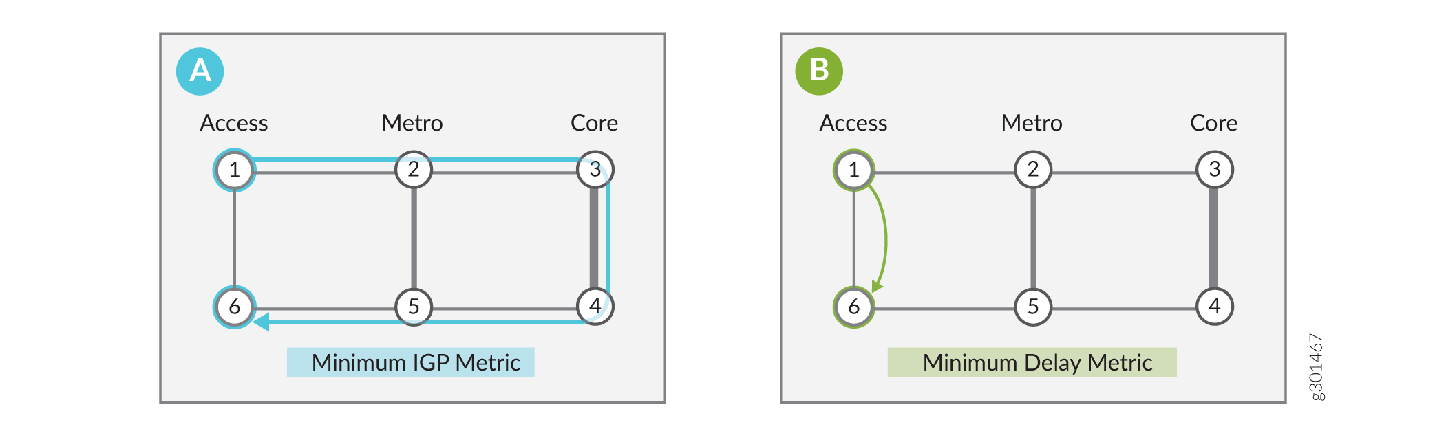
このシナリオでは、コア ネットワークは安価ですが、遅延が長くなります。アクセスのショートカットは、遅延が最も少ないため、高価です。コアネットワークはより安価であるため、通常、トラフィックの大部分は最小IGPメトリックを使用して1>2>3>4>5>から6に移動します。シナリオa)に示されているように、適切なコストを設定し、デフォルトのIS-ISアルゴリズムをゼロに設定してIS-ISを実行することで、IGPの最小要件を達成できます。超低遅延が重要なビジネスでは、パケットを1から6にする必要があります。シナリオb)に示されているように、最小遅延のIS-ISフレックスアルゴリズムを定義することで、エンドポイントまでの遅延を最小限に抑える最小遅延メトリックを実現できます。この flex アルゴリズムは、ノード 1 とノード 6 のみで構成されます。
例:レイヤー 3 仮想プライベート ネットワーク(VPN)で、ネットワークのソース パケット ルーティング(SPRING)で IS-IS リンク遅延を有効にする
この例では、レイヤー3 VPNシナリオでSPRINGを使用してIS-ISリンク遅延を設定する方法を示しています。この例では、PE1とPE2の間に2つのVPNを作成できます。VPN1はリンク遅延を最適化し、VPN2はIGPメトリックを最適化します。この機能を設定して、テスト トポロジーで双方向トラフィックを有効にすることもできますが、この例では単方向トラフィックのシナリオに焦点を当てています。具体的には、あなたの仕事は、PE1によってPE2によってアドバタイズされた宛先にPE1によって送信されたレイヤー3 VPNトラフィックの転送パスを制御することです。
必要条件
この例では、以下のハードウェアとソフトウェアのコンポーネントを使用しています。
-
MXシリーズルーター4台
-
すべてのデバイスでJunos OS リリース 21.1R1 以降が作動
位相幾何学
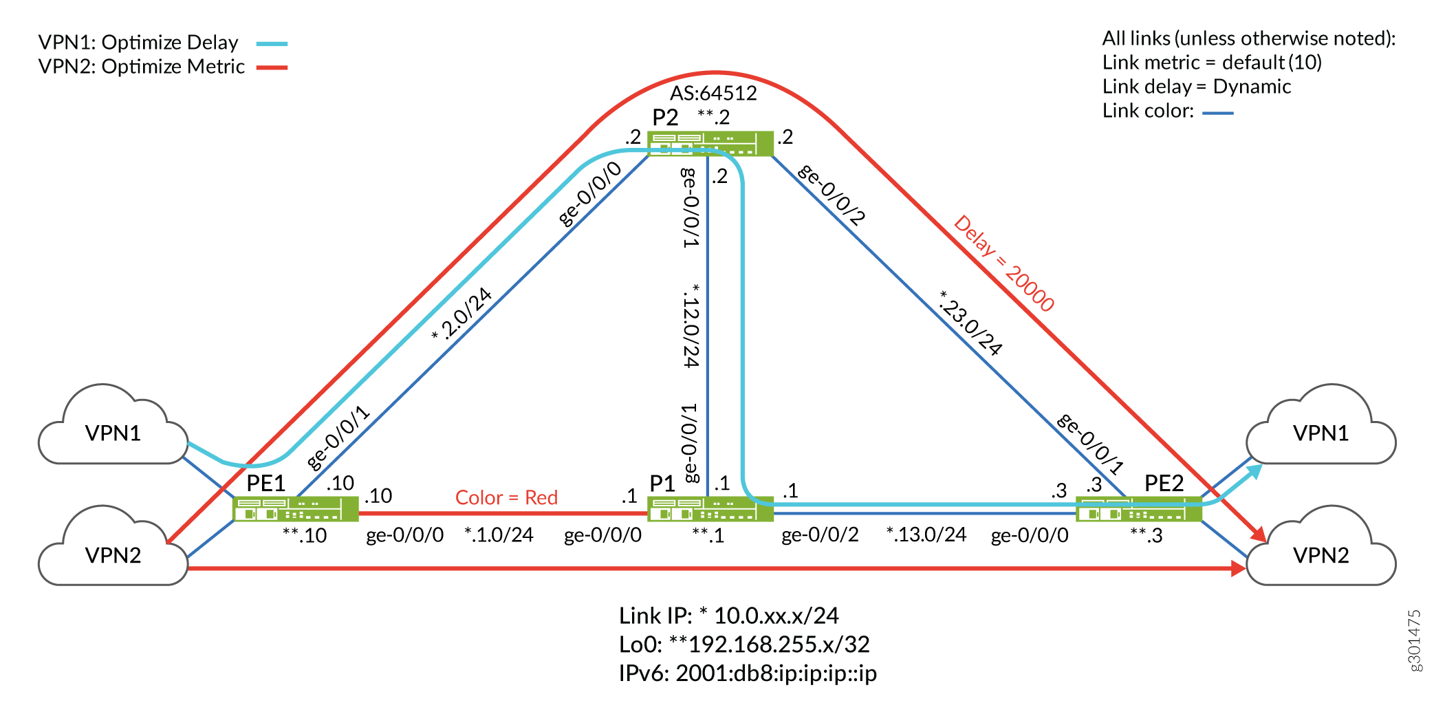
トポロジーでは、ほとんどのリンクの(デフォルトの)IGPメトリックは10、動的遅延測定、青色のカラーリングを備えています。例外は、PE1とP1の間の赤色のパスと、P2からPE2へのリンクの静的遅延設定です。
IPv4とIPv6の両方でIS-ISリンク遅延をサポートするようにテストトポロジーを設定しました。P2ルーターをルートリフレクタとして設定し、PEデバイスをクライアントとして設定しました。トポロジーをシンプルに保つために、PE2 ルーターの VRF でスタティック ルートを使用しています。これにより、CE デバイスや EBGP などの PE-CE ルーティング プロトコルが不要になります。
目標は、PE2 によって VPN1 用にアドバタイズされたルートが、青色のリンクのみを使用するように制限しながら、遅延を最適化するパスを取るようにネットワークを構成することです。対照的に、VPN2に関連付けられたルートに送信されるトラフィックは、IGPメトリックに基づくパス最適化により、青または赤のリンクのいずれかを取ることができます。
- VPN1 の Flex Algorithm Definition(FAD)では、アルゴリズム 128 を使用しています。遅延を減らすために最適化されたパス上で、青色のリンク(PE1>P2>P1>PE2)のみを使用するように設定しました。適切なパス選択を示すために、P2とPE2の間に20000マイクロ秒の静的遅延を設定します。この遅延は、残りのリンクで測定された動的遅延よりも大幅に大きくなります。その結果、フレックス アルゴリズム 128 トラフィックは P2 から PE2 へのリンクを回避し、代わりに青色のパス(PE1>P2>P1>PE2)に沿った追加のホップを優先することが予想されます。
- VPN2 の Flex Algorithm Definition(FAD)は、アルゴリズム 129 を使用します。青または赤のリンク(PE1>P1>PE2またはPE1>P2>PE2)を使用するように設定し、パスはIGPメトリックで最適化されています。その結果、フレックスアルゴリズム129を使用するトラフィックは、PE1とPE2の間に2つの等コストパスを持ち、どちらも2つのホップとその結果のメトリック20を負担する。
概要
IPネットワークでは、トラフィックの大部分がコアネットワークを経由することが多いため、コストは削減されますが、レイテンシが増加する可能性があります。しかし、ビジネストラフィックは、単にIGPメトリックに基づく従来のパス最適化を中継するのではなく、パス遅延などの他のパフォーマンスメトリックに基づいてパス選択の決定を行う機能からメリットを受けることがよくあります。パスを最適化して遅延を減らすことは、リアルタイムの音声やビデオなどのアプリケーションに大きなメリットをもたらします。また、ミリ秒単位が大きな利益または損失につながる可能性のある金融市場データへの高性能アクセスも可能になります。
Junos OS リリース 21.1R1 以降では、IP ネットワークで IS-IS リンク遅延を有効にできます。デフォルトのIS-ISアルゴリズム(0)を使用して、適切なリンクコストでIS-ISを設定することで、最小IGPメトリックパスを実現できます。これにより、リンクメトリックの合計に厳密に基づいてエンドポイントへのパスが最適化されます。IS-IS遅延フレックスアルゴリズムを使用すると、エンドツーエンドの遅延に基づいてパスを最適化できます。
リンク遅延は、TWAMP(Two-Way Active Measurement Probes)を使用して動的に測定できます。次に、ルーターはリンク遅延パラメータをフラッディングします。エリア内のルーターは、これらのパラメータを共有リンクステートデータベース(LSDB)に保存します。イングレスノードは、LSDBに対してSPFアルゴリズムを実行し、リンクカラー、IGPメトリック、トラフィックエンジニアリング(TE)メトリック、またはこの例に示すようにリンク遅延など、さまざまな属性で最適化されたパスを計算します。
egressルーターは、BGP を介してアドバタイズされたルートに関連するカラーコミュニティをアタッチすることによって、どのフレックスアルゴリズムが望ましいかを知らせます。送信側(リモート PE によってアドバタイズされたタグ付きルートを受信したローカル PE)では、これらのカラー コミュニティを使用して、リモート プロトコル ネクスト ホップ(PE のループバック アドレス)をフレックス アルゴリズム識別子に解決するカラー テーブルにインデックスが作成されます。レイヤー 3 VPN のコンテキストでは、カラー マッピング ポリシーがイングレス ノードで使用され、カラー テーブルを介してネクスト ホップを解決するプレフィックスが選択されます。
次に、ローカル PE はローカルの Flex Algorithm Definition(FAD)を使用して、フレックス アルゴリズム識別子をパス選択基準のセットにマッピングします(例:「青色のリンクを使用し、遅延時に最適化する」)。イングレスPEは、LSDBの値に基づいて最適なパスを計算し、関連するMPLSラベルスタックをパケットにプッシュして、関連するネクストホップに送信します。これにより、シグナリング プロトコルとして IS-IS を使用するトラフィック制御 MPLS パスが生成されます。
構成
CLIクイック構成
この例を素早く設定するには、以下のコマンドをコピーしてテキストファイルに貼り付け、改行を削除し、ネットワーク設定に合わせて必要な詳細を変更し、コマンドを[edit]階層レベルのCLIにコピー&ペーストしてください。
MXシリーズ ルーターのMPCのタイプによっては、IS-IS遅延機能をサポートするために、拡張IPサービスを明示的に有効にする必要がある場合があります。 set chassis network-services enhanced-ip 設定ステートメントをコミットすると、システムを再起動するように求められます。
PE1
set system host-name PE1
set chassis network-services enhanced-ip
set services rpm twamp server authentication-mode none
set services rpm twamp server light
set interfaces ge-0/0/0 description To_R1
set interfaces ge-0/0/0 unit 0 family inet address 10.0.1.10/24
set interfaces ge-0/0/0 unit 0 family iso
set interfaces ge-0/0/0 unit 0 family inet6 address 2001:db8:10:0:1::10/80
set interfaces ge-0/0/0 unit 0 family mpls maximum-labels 16
set interfaces ge-0/0/1 description To_R2
set interfaces ge-0/0/1 unit 0 family inet address 10.0.2.10/24
set interfaces ge-0/0/1 unit 0 family iso
set interfaces ge-0/0/1 unit 0 family inet6 address 2001:db8:10:0:2::10/80
set interfaces ge-0/0/1 unit 0 family mpls maximum-labels 16
set interfaces lo0 unit 0 family inet address 192.168.255.10/32
set interfaces lo0 unit 0 family inet address 127.0.0.1/32
set interfaces lo0 unit 0 family iso address 49.0001.000a.0a0a.0a00
set interfaces lo0 unit 0 family inet6 address 2001:db8:192:168:255::10/128
set interfaces lo0 unit 1 family inet address 172.16.10.1/32
set interfaces lo0 unit 1 family inet6 address 2001:db8:172:16:10::1/128
set interfaces lo0 unit 2 family inet address 172.16.10.2/32
set interfaces lo0 unit 2 family inet6 address 2001:db8:172:16:10::2/128
set policy-options policy-statement pplb then load-balance per-packet
set policy-options policy-statement prefix-sid term 1 from route-filter 192.168.255.10/32 exact
set policy-options policy-statement prefix-sid term 1 then prefix-segment algorithm 128 index 1280
set policy-options policy-statement prefix-sid term 1 then prefix-segment algorithm 128 node-segment
set policy-options policy-statement prefix-sid term 1 then prefix-segment algorithm 129 index 1290
set policy-options policy-statement prefix-sid term 1 then prefix-segment algorithm 129 node-segment
set policy-options policy-statement prefix-sid term 1 then prefix-segment index 1000
set policy-options policy-statement prefix-sid term 1 then prefix-segment node-segment
set policy-options policy-statement prefix-sid term 1 then accept
set policy-options policy-statement prefix-sid term 2 from route-filter 2001:db8:192:168:255::10/128 exact
set policy-options policy-statement prefix-sid term 2 then prefix-segment algorithm 128 index 4280
set policy-options policy-statement prefix-sid term 2 then prefix-segment algorithm 128 node-segment
set policy-options policy-statement prefix-sid term 2 then prefix-segment algorithm 129 index 4290
set policy-options policy-statement prefix-sid term 2 then prefix-segment algorithm 129 node-segment
set policy-options policy-statement prefix-sid term 2 then prefix-segment index 4000
set policy-options policy-statement prefix-sid term 2 then prefix-segment node-segment
set policy-options policy-statement prefix-sid term 2 then accept
set policy-options policy-statement v6vpn1_res_map1 from route-filter 2001:db8:172:16:1::/80 orlonger
set policy-options policy-statement v6vpn1_res_map1 then accept
set policy-options policy-statement v6vpn1_res_map1 then resolution-map map1
set policy-options policy-statement v6vpn2_res_map1 from route-filter 2001:db8:172:16:2::/80 orlonger
set policy-options policy-statement v6vpn2_res_map1 then accept
set policy-options policy-statement v6vpn2_res_map1 then resolution-map map1
set policy-options policy-statement vpn1_res_map1 term 1 from route-filter 172.16.1.0/24 orlonger
set policy-options policy-statement vpn1_res_map1 term 1 then accept
set policy-options policy-statement vpn1_res_map1 term 1 then resolution-map map1
set policy-options policy-statement vpn2_res_map1 term 1 from route-filter 172.16.2.0/24 orlonger
set policy-options policy-statement vpn2_res_map1 term 1 then accept
set policy-options policy-statement vpn2_res_map1 term 1 then resolution-map map1
set policy-options resolution-map map1 mode ip-color
set routing-instances vpn1 instance-type vrf
set routing-instances vpn1 interface lo0.1
set routing-instances vpn1 route-distinguisher 64512:1
set routing-instances vpn1 vrf-target target:64512:1
set routing-instances vpn1 vrf-table-label
set routing-instances vpn2 instance-type vrf
set routing-instances vpn2 interface lo0.2
set routing-instances vpn2 route-distinguisher 64512:2
set routing-instances vpn2 vrf-target target:64512:2
set routing-instances vpn2 vrf-table-label
set protocols bgp group to-RRv6 type internal
set protocols bgp group to-RRv6 local-address 2001:db8:192:168:255::10
set protocols bgp group to-RRv6 import v6vpn1_res_map1
set protocols bgp group to-RRv6 import v6vpn2_res_map1
set protocols bgp group to-RRv6 family inet6 unicast extended-nexthop-color
set protocols bgp group to-RRv6 family inet6-vpn unicast
set protocols bgp group to-RRv6 neighbor 2001:db8:192:168:255::2
set protocols bgp group to-RR type internal
set protocols bgp group to-RR local-address 192.168.255.10
set protocols bgp group to-RR import vpn1_res_map1
set protocols bgp group to-RR import vpn2_res_map1
set protocols bgp group to-RR family inet unicast extended-nexthop-color
set protocols bgp group to-RR family inet-vpn unicast
set protocols bgp group to-RR family traffic-engineering unicast
set protocols bgp group to-RR neighbor 192.168.255.2
set protocols bgp group to-RR vpn-apply-export
set protocols isis interface ge-0/0/0.0 level 2 post-convergence-lfa node-protection
set protocols isis interface ge-0/0/0.0 delay-measurement advertisement periodic threshold 100
set protocols isis interface ge-0/0/0.0 point-to-point
set protocols isis interface ge-0/0/1.0 level 2 post-convergence-lfa node-protection
set protocols isis interface ge-0/0/1.0 delay-measurement advertisement periodic threshold 100
set protocols isis interface ge-0/0/1.0 point-to-point
set protocols isis interface lo0.0 passive
set protocols isis source-packet-routing srgb start-label 80000
set protocols isis source-packet-routing srgb index-range 5000
set protocols isis source-packet-routing flex-algorithm 128
set protocols isis source-packet-routing flex-algorithm 129
set protocols isis level 1 disable
set protocols isis backup-spf-options use-post-convergence-lfa maximum-backup-paths 8
set protocols isis backup-spf-options use-source-packet-routing
set protocols isis traffic-engineering l3-unicast-topology
set protocols isis traffic-engineering advertisement always
set protocols isis export prefix-sid
set protocols mpls traffic-engineering
set protocols mpls admin-groups RED 0
set protocols mpls admin-groups BLUE 1
set protocols mpls icmp-tunneling
set protocols mpls interface all
set protocols mpls interface fxp0.0 disable
set protocols mpls interface ge-0/0/0.0 admin-group RED
set protocols mpls interface ge-0/0/1.0 admin-group BLUE
set routing-options flex-algorithm 128 definition metric-type delay-metric
set routing-options flex-algorithm 128 definition spf
set routing-options flex-algorithm 128 definition admin-group include-any BLUE
set routing-options flex-algorithm 129 definition metric-type igp-metric
set routing-options flex-algorithm 129 definition spf
set routing-options flex-algorithm 129 definition admin-group include-any RED
set routing-options flex-algorithm 129 definition admin-group include-any BLUE
set routing-options router-id 192.168.255.10
set routing-options autonomous-system 64512
set routing-options forwarding-table export pplb
set routing-options forwarding-table ecmp-fast-reroute
set routing-options forwarding-table chained-composite-next-hop ingress l3vpn
P1の
set system host-name P1
set chassis network-services enhanced-ip
set services rpm twamp server authentication-mode none
set services rpm twamp server light
set interfaces ge-0/0/0 description To_R0
set interfaces ge-0/0/0 unit 0 family inet address 10.0.1.1/24
set interfaces ge-0/0/0 unit 0 family iso
set interfaces ge-0/0/0 unit 0 family inet6 address 2001:db8:10:0:1::1/80
set interfaces ge-0/0/0 unit 0 family mpls maximum-labels 16
set interfaces ge-0/0/1 description To_R2
set interfaces ge-0/0/1 unit 0 family inet address 10.0.12.1/24
set interfaces ge-0/0/1 unit 0 family iso
set interfaces ge-0/0/1 unit 0 family inet6 address 2001:db8:10:0:12::1/80
set interfaces ge-0/0/1 unit 0 family mpls maximum-labels 16
set interfaces ge-0/0/2 description To_R3
set interfaces ge-0/0/2 unit 0 family inet address 10.0.13.1/24
set interfaces ge-0/0/2 unit 0 family iso
set interfaces ge-0/0/2 unit 0 family inet6 address 2001:db8:10:0:13::1/80
set interfaces ge-0/0/2 unit 0 family mpls maximum-labels 16
set interfaces lo0 unit 0 family inet address 192.168.255.1/32
set interfaces lo0 unit 0 family iso address 49.0001.0005.0505.0500
set interfaces lo0 unit 0 family inet6 address 2001:db8:192:168:255::1/128
set policy-options policy-statement pplb then load-balance per-packet
set policy-options policy-statement prefix-sid term 1 from route-filter 192.168.255.1/32 exact
set policy-options policy-statement prefix-sid term 1 then prefix-segment algorithm 128 index 1281
set policy-options policy-statement prefix-sid term 1 then prefix-segment algorithm 128 node-segment
set policy-options policy-statement prefix-sid term 1 then prefix-segment algorithm 129 index 1291
set policy-options policy-statement prefix-sid term 1 then prefix-segment algorithm 129 node-segment
set policy-options policy-statement prefix-sid term 1 then prefix-segment index 1001
set policy-options policy-statement prefix-sid term 1 then prefix-segment node-segment
set policy-options policy-statement prefix-sid term 1 then accept
set policy-options policy-statement prefix-sid term 2 from route-filter 2001:db8:192:168:255::1/128 exact
set policy-options policy-statement prefix-sid term 2 then prefix-segment algorithm 128 index 4281
set policy-options policy-statement prefix-sid term 2 then prefix-segment algorithm 128 node-segment
set policy-options policy-statement prefix-sid term 2 then prefix-segment algorithm 129 index 4291
set policy-options policy-statement prefix-sid term 2 then prefix-segment algorithm 129 node-segment
set policy-options policy-statement prefix-sid term 2 then prefix-segment index 4001
set policy-options policy-statement prefix-sid term 2 then prefix-segment node-segment
set policy-options policy-statement prefix-sid term 2 then accept
set protocols isis interface ge-0/0/0.0 level 2 post-convergence-lfa node-protection
set protocols isis interface ge-0/0/0.0 delay-measurement advertisement periodic threshold 100
set protocols isis interface ge-0/0/0.0 point-to-point
set protocols isis interface ge-0/0/1.0 level 2 post-convergence-lfa node-protection
set protocols isis interface ge-0/0/1.0 delay-measurement advertisement periodic threshold 100
set protocols isis interface ge-0/0/1.0 point-to-point
set protocols isis interface ge-0/0/2.0 level 2 post-convergence-lfa node-protection
set protocols isis interface ge-0/0/2.0 delay-measurement advertisement periodic threshold 100
set protocols isis interface ge-0/0/2.0 point-to-point
set protocols isis interface lo0.0 passive
set protocols isis source-packet-routing srgb start-label 80000
set protocols isis source-packet-routing srgb index-range 5000
set protocols isis source-packet-routing flex-algorithm 128
set protocols isis source-packet-routing flex-algorithm 129
set protocols isis level 1 disable
set protocols isis backup-spf-options use-post-convergence-lfa maximum-backup-paths 8
set protocols isis backup-spf-options use-source-packet-routing
set protocols isis traffic-engineering l3-unicast-topology
set protocols isis traffic-engineering advertisement always
set protocols isis export prefix-sid
set protocols mpls admin-groups RED 0
set protocols mpls admin-groups BLUE 1
set protocols mpls icmp-tunneling       set protocols mpls interface all
set protocols mpls interface fxp0.0 disable
set protocols mpls interface ge-0/0/0.0 admin-group RED
set protocols mpls interface ge-0/0/1.0 admin-group BLUE
set protocols mpls interface ge-0/0/2.0 admin-group BLUE
set routing-options router-id 192.168.255.1
set routing-options autonomous-system 65412
set routing-options forwarding-table export pplb
P2の
set system host-name P2
set chassis network-services enhanced-ip
set services rpm twamp server authentication-mode none
set services rpm twamp server light
set interfaces ge-0/0/0 unit 0 family inet address 10.0.2.2/24
set interfaces ge-0/0/0 unit 0 family iso
set interfaces ge-0/0/0 unit 0 family inet6 address 2001:db8:10:0:2::2/80
set interfaces ge-0/0/0 unit 0 family mpls maximum-labels 16
set interfaces ge-0/0/1 description To_R1
set interfaces ge-0/0/1 unit 0 family inet address 10.0.12.2/24
set interfaces ge-0/0/1 unit 0 family iso
set interfaces ge-0/0/1 unit 0 family inet6 address 2001:db8:10:0:12::2/80
set interfaces ge-0/0/1 unit 0 family mpls maximum-labels 16
set interfaces ge-0/0/2 description To_R3
set interfaces ge-0/0/2 unit 0 family inet address 10.0.23.2/24
set interfaces ge-0/0/2 unit 0 family iso
set interfaces ge-0/0/2 unit 0 family inet6 address 2001:db8:10:0:23::2/80
set interfaces ge-0/0/2 unit 0 family mpls maximum-labels 16
set interfaces lo0 unit 0 family inet address 192.168.255.2/32
set interfaces lo0 unit 0 family iso address 49.0001.0002.0202.0200
set interfaces lo0 unit 0 family inet6 address 2001:db8:192:168:255::2/128
set policy-options policy-statement pplb then load-balance per-packet
set policy-options policy-statement prefix-sid term 1 from route-filter 192.168.255.2/32 exact
set policy-options policy-statement prefix-sid term 1 then prefix-segment algorithm 128 index 1282
set policy-options policy-statement prefix-sid term 1 then prefix-segment algorithm 128 node-segment
set policy-options policy-statement prefix-sid term 1 then prefix-segment algorithm 129 index 1292
set policy-options policy-statement prefix-sid term 1 then prefix-segment algorithm 129 node-segment
set policy-options policy-statement prefix-sid term 1 then prefix-segment index 1002
set policy-options policy-statement prefix-sid term 1 then prefix-segment node-segment
set policy-options policy-statement prefix-sid term 1 then accept
set policy-options policy-statement prefix-sid term 2 from route-filter 2001:db8:192:168:255::2/128 exact
set policy-options policy-statement prefix-sid term 2 then prefix-segment algorithm 128 index 4282
set policy-options policy-statement prefix-sid term 2 then prefix-segment algorithm 128 node-segment
set policy-options policy-statement prefix-sid term 2 then prefix-segment algorithm 129 index 4292
set policy-options policy-statement prefix-sid term 2 then prefix-segment algorithm 129 node-segment
set policy-options policy-statement prefix-sid term 2 then prefix-segment index 4002
set policy-options policy-statement prefix-sid term 2 then prefix-segment node-segment
set policy-options policy-statement prefix-sid term 2 then accept
set policy-options policy-statement ted2nlri_igp term 1 from family traffic-engineering
set policy-options policy-statement ted2nlri_igp term 1 from protocol isis
set policy-options policy-statement ted2nlri_igp term 1 then accept
set protocols bgp group to-RRv6 type internal
set protocols bgp group to-RRv6 local-address 2001:db8:192:168:255::2
set protocols bgp group to-RRv6 family inet6 unicast
set protocols bgp group to-RRv6 family inet6-vpn unicast
set protocols bgp group to-RRv6 neighbor 2001:db8:192:168:255::10
set protocols bgp group to-RRv6 neighbor 2001:db8:192:168:255::3
set protocols bgp group to-RR type internal
set protocols bgp group to-RR local-address 192.168.255.2
set protocols bgp group to-RR family inet unicast
set protocols bgp group to-RR family inet-vpn unicast
set protocols bgp group to-RR neighbor 192.168.255.10
set protocols bgp group to-RR neighbor 192.168.255.3
set protocols bgp cluster 192.168.255.2
set protocols isis interface ge-0/0/0.0 level 2 post-convergence-lfa node-protection
set protocols isis interface ge-0/0/0.0 delay-measurement advertisement periodic threshold 100
set protocols isis interface ge-0/0/0.0 point-to-point
set protocols isis interface ge-0/0/1.0 level 2 post-convergence-lfa node-protection
set protocols isis interface ge-0/0/1.0 delay-measurement advertisement periodic threshold 100
set protocols isis interface ge-0/0/1.0 point-to-point
set protocols isis interface ge-0/0/2.0 level 2 post-convergence-lfa node-protection
set protocols isis interface ge-0/0/2.0 delay-metric 20000
set protocols isis interface ge-0/0/2.0 delay-measurement advertisement periodic threshold 100
set protocols isis interface ge-0/0/2.0 point-to-point
set protocols isis interface lo0.0 passive
set protocols isis source-packet-routing srgb start-label 80000
set protocols isis source-packet-routing srgb index-range 5000
set protocols isis source-packet-routing flex-algorithm 128
set protocols isis source-packet-routing flex-algorithm 129
set protocols isis level 1 disable
set protocols isis backup-spf-options use-post-convergence-lfa maximum-backup-paths 8
set protocols isis backup-spf-options use-source-packet-routing
set protocols isis traffic-engineering l3-unicast-topology
set protocols isis traffic-engineering advertisement always
set protocols isis export prefix-sid
set protocols mpls traffic-engineering
set protocols mpls admin-groups RED 0
set protocols mpls admin-groups BLUE 1
set protocols mpls icmp-tunneling       set protocols mpls interface all
set protocols mpls interface fxp0.0 disable
set protocols mpls interface ge-0/0/0.0 admin-group BLUE
set protocols mpls interface ge-0/0/1.0 admin-group BLUE
set protocols mpls interface ge-0/0/2.0 admin-group BLUE
set routing-options router-id 192.168.255.2
set routing-options autonomous-system 64512
set routing-options forwarding-table export pplb
PE2の
set system host-name PE2
set chassis network-services enhanced-ip
set services rpm twamp server authentication-mode none
set services rpm twamp server light
set interfaces ge-0/0/0 description To_R1
set interfaces ge-0/0/0 unit 0 family inet address 10.0.13.3/24
set interfaces ge-0/0/0 unit 0 family iso
set interfaces ge-0/0/0 unit 0 family inet6 address 2001:db8:10:0:13::3/80
set interfaces ge-0/0/0 unit 0 family mpls maximum-labels 16
set interfaces ge-0/0/1 description To_R2
set interfaces ge-0/0/1 unit 0 family inet address 10.0.23.3/24
set interfaces ge-0/0/1 unit 0 family iso
set interfaces ge-0/0/1 unit 0 family inet6 address 2001:db8:10:0:23::364/128
set interfaces ge-0/0/1 unit 0 family mpls maximum-labels 16
set interfaces lo0 unit 0 family inet address 192.168.255.3/32
set interfaces lo0 unit 0 family inet address 127.0.0.1/32
set interfaces lo0 unit 0 family iso address 49.0001.0007.0707.0700
set interfaces lo0 unit 0 family inet6 address 2001:db8:192:168:255::3/128
set interfaces lo0 unit 1 family inet address 172.16.3.1/32
set interfaces lo0 unit 1 family inet6 address 2001:db8:172:16:3::1/128
set interfaces lo0 unit 2 family inet address 172.16.3.2/32
set interfaces lo0 unit 2 family inet6 address 2001:db8:172:16:3::2/128
set policy-options policy-statement pplb then load-balance per-packet
set policy-options policy-statement prefix-sid term 1 from route-filter 192.168.255.3/32 exact
set policy-options policy-statement prefix-sid term 1 then prefix-segment algorithm 128 index 1283
set policy-options policy-statement prefix-sid term 1 then prefix-segment algorithm 128 node-segment
set policy-options policy-statement prefix-sid term 1 then prefix-segment algorithm 129 index 1293
set policy-options policy-statement prefix-sid term 1 then prefix-segment algorithm 129 node-segment
set policy-options policy-statement prefix-sid term 1 then prefix-segment index 1003
set policy-options policy-statement prefix-sid term 1 then prefix-segment node-segment
set policy-options policy-statement prefix-sid term 1 then accept
set policy-options policy-statement prefix-sid term 2 from route-filter 2001:db8:192:168:255::3/128 exact
set policy-options policy-statement prefix-sid term 2 then prefix-segment algorithm 128 index 4283
set policy-options policy-statement prefix-sid term 2 then prefix-segment algorithm 128 node-segment
set policy-options policy-statement prefix-sid term 2 then prefix-segment algorithm 129 index 4293
set policy-options policy-statement prefix-sid term 2 then prefix-segment algorithm 129 node-segment
set policy-options policy-statement prefix-sid term 2 then prefix-segment index 4003
set policy-options policy-statement prefix-sid term 2 then prefix-segment node-segment
set policy-options policy-statement prefix-sid term 2 then accept
set policy-options policy-statement vpn_1_export term 1 from route-filter 172.16.1.0/24 orlonger
set policy-options policy-statement vpn_1_export term 1 then community add color128
set policy-options policy-statement vpn_1_export term 1 then next-hop 192.168.255.3
set policy-options policy-statement vpn_1_export term 1 then accept
set policy-options policy-statement vpn_1_export_v6 term 1 from route-filter 2001:db8:172:16:1::/80 orlonger
set policy-options policy-statement vpn_1_export_v6 term 1 then community add color128
set policy-options policy-statement vpn_1_export_v6 term 1 then next-hop 2001:db8:192:168:255::3
set policy-options policy-statement vpn_1_export_v6 term 1 then accept
set policy-options policy-statement vpn_1_export_v6 term 2 from route-filter 2001:db8:172:16:3::1/128 exact
set policy-options policy-statement vpn_1_export_v6 term 2 then community add color128
set policy-options policy-statement vpn_1_export_v6 term 2 then next-hop 2001:db8:192:168:255::3
set policy-options policy-statement vpn_1_export_v6 term 2 then accept
set policy-options policy-statement vpn_2_export term 1 from route-filter 172.16.2.0/24 orlonger
set policy-options policy-statement vpn_2_export term 1 then community add color129
set policy-options policy-statement vpn_2_export term 1 then next-hop 192.168.255.3
set policy-options policy-statement vpn_2_export term 1 then accept
set policy-options policy-statement vpn_2_export_v6 term 1 from route-filter 2001:db8:172:16:2::/80 orlonger
set policy-options policy-statement vpn_2_export_v6 term 1 then community add color129
set policy-options policy-statement vpn_2_export_v6 term 1 then next-hop 2001:db8:192:168:255::3
set policy-options policy-statement vpn_2_export_v6 term 1 then accept
set policy-options community color128 members color:0:128
set policy-options community color129 members color:0:129
set policy-options resolution-map map1 mode ip-color
set routing-instances vpn1 instance-type vrf
set routing-instances vpn1 routing-options rib vpn1.inet6.0 static route 2001:db8:172:16:1::/80 receive
set routing-instances vpn1 routing-options static route 172.16.1.0/24 receive
set routing-instances vpn1 interface lo0.1
set routing-instances vpn1 route-distinguisher 64512:1
set routing-instances vpn1 vrf-target target:64512:1
set routing-instances vpn1 vrf-table-label
set routing-instances vpn2 instance-type vrf
set routing-instances vpn2 routing-options rib vpn2.inet6.0 static route 2001:db8:172:16:2::/80 receive
set routing-instances vpn2 routing-options static route 172.16.2.0/24 receive
set routing-instances vpn2 interface lo0.2
set routing-instances vpn2 route-distinguisher 64512:2
set routing-instances vpn2 vrf-target target:64512:2
set routing-instances vpn2 vrf-table-label
set protocols bgp group to-RRv6 type internal
set protocols bgp group to-RRv6 local-address 2001:db8:192:168:255::3
set protocols bgp group to-RRv6 family inet6 unicast extended-nexthop-color
set protocols bgp group to-RRv6 family inet6-vpn unicast
set protocols bgp group to-RRv6 export vpn_1_export_v6
set protocols bgp group to-RRv6 export vpn_2_export_v6
set protocols bgp group to-RRv6 neighbor 2001:db8:192:168:255::2
set protocols bgp group to-RRv6 vpn-apply-export
set protocols bgp group to-RR type internal
set protocols bgp group to-RR local-address 192.168.255.3
set protocols bgp group to-RR family inet unicast extended-nexthop-color
set protocols bgp group to-RR family inet-vpn unicast
set protocols bgp group to-RR export vpn_1_export
set protocols bgp group to-RR export vpn_2_export
set protocols bgp group to-RR neighbor 192.168.255.2
set protocols bgp group to-RR vpn-apply-export
set protocols isis interface ge-0/0/0.0 level 2 post-convergence-lfa node-protection
set protocols isis interface ge-0/0/0.0 delay-measurement advertisement periodic threshold 100
set protocols isis interface ge-0/0/0.0 point-to-point
set protocols isis interface ge-0/0/1.0 level 2 post-convergence-lfa node-protection
set protocols isis interface ge-0/0/1.0 delay-measurement advertisement periodic threshold 100
set protocols isis interface ge-0/0/1.0 point-to-point
set protocols isis interface ge-0/0/2.0 delay-metric 20000
set protocols isis interface lo0.0 passive
set protocols isis source-packet-routing srgb start-label 80000
set protocols isis source-packet-routing srgb index-range 5000
set protocols isis source-packet-routing flex-algorithm 128
set protocols isis source-packet-routing flex-algorithm 129
set protocols isis level 1 disable
set protocols isis backup-spf-options use-post-convergence-lfa maximum-backup-paths 8
set protocols isis backup-spf-options use-source-packet-routing
set protocols isis traffic-engineering l3-unicast-topology
set protocols isis traffic-engineering advertisement always
set protocols isis export prefix-sid
set protocols mpls admin-groups RED 0
set protocols mpls admin-groups BLUE 1
set protocols mpls icmp-tunneling       set protocols mpls interface all
set protocols mpls interface fxp0.0 disable
set protocols mpls interface ge-0/0/0.0 admin-group BLUE
set protocols mpls interface ge-0/0/1.0 admin-group BLUEset routing-options router-id 192.168.255.3
set routing-options autonomous-system 64512
set routing-options forwarding-table export pplb
set routing-options forwarding-table ecmp-fast-reroute
set routing-options forwarding-table chained-composite-next-hop ingress l3vpn
手順
-
ホスト名、IPv4、IPv6アドレス、ループバックインターフェイスアドレス、
enhanced-ipモードなどの基本的なデバイス設定を行い、4つすべてのルーターのすべてのインターフェイスでISOおよびMPLSプロトコルファミリーを有効にします。user@PE1# set system host-name PE1 set chassis network-services enhanced-ip set interfaces ge-0/0/0 description To_R1 set interfaces ge-0/0/0 unit 0 family inet address 10.0.1.10/24 set interfaces ge-0/0/0 unit 0 family iso set interfaces ge-0/0/0 unit 0 family inet6 address 2001:db8:10:0:1::10/80 set interfaces ge-0/0/0 unit 0 family mpls maximum-labels 16 set interfaces ge-0/0/1 description To_R2 set interfaces ge-0/0/1 unit 0 family inet address 10.0.2.10/24 set interfaces ge-0/0/1 unit 0 family iso set interfaces ge-0/0/1 unit 0 family inet6 address 2001:db8:10:0:2::10/80 set interfaces ge-0/0/1 unit 0 family mpls maximum-labels 16 set interfaces lo0 unit 0 family inet address 192.168.255.10/32 set interfaces lo0 unit 0 family inet address 127.0.0.1/32 set interfaces lo0 unit 0 family iso address 49.0001.000a.0a0a.0a00 set interfaces lo0 unit 0 family inet6 address 2001:db8:192:168:255::10/128 set interfaces lo0 unit 1 family inet address 172.16.10.1/32 set interfaces lo0 unit 1 family inet6 address 2001:db8:172:16:10::1/128 set interfaces lo0 unit 2 family inet address 172.16.10.2/32 set interfaces lo0 unit 2 family inet6 address 2001:db8:172:16:10::2/128
-
ルーター ID、自律システム(AS)番号を設定し、すべてのルーターのロードバランシング エクスポート ポリシーを転送テーブルに適用して、トラフィックのロードバランシングを有効にします。
user@PE1#
set routing-options router-id 192.168.255.10
set routing-options autonomous-system 64512
set routing-options forwarding-table export pplb
-
PE1とPE2では、ECMP(等価コストマルチパス)を設定して、高速再ルート保護を有効にします。また、連鎖された複合ネクストホップを設定して、ルーターが同じ宛先を共有するルートを共通の転送ネクストホップに向けられるようにします。このオプションにより、転送情報ベース(FIB)のスケーリングが向上します。
user@PE1#
set routing-options forwarding-table ecmp-fast-reroute
set routing-options forwarding-table chained-composite-next-hop ingress l3vpn
-
すべてのルーターのすべてのインターフェイスで MPLS プロトコル処理を有効にします。トラフィック制御も有効にします。
user@PE1#
set protocols mpls interface fxp0.0 disable
set protocols mpls interface all
set protocols mpls traffic-engineering
-
すべてのルーターでTWAMPプローブを有効にします。これらのプローブは、ルーターの各ペア間のリンク遅延の動的測定をサポートします。
user@PE1#
set services rpm twamp server authentication-mode none
set services rpm twamp server light
-
IS-IS プロトコルをポイントツーポイント動作に設定し(TWAMP ベースの遅延測定はマルチポイント リンクではサポートされていません)、すべてのインターフェイスで Topology-Independent Loop-Free Alternate(TILFA)動作のノード保護モードを有効にします。また、ループバック インターフェイスでパッシブ モードの IS-IS を有効にし、IS-IS レベル 1 を無効にして IS-IS レベル 2 のみを使用します。レイヤー3ユニキャストトポロジーでトラフィック制御を有効にして、IGPトポロジーをTEDにダウンロードします。SPRINGルーティングパスをサポートするようにIS-ISを設定します。 prefix-sid エクスポート・ポリシーは、次のステップで定義します。このポリシーは、ローカルノードに、1つ以上のフレックスアルゴリズムへのマッピングでループバックアドレスをアドバタイズさせるために使用されます。
user@PE1#
set protocols isis level 1 disable
set protocols isis interface ge-0/0/0.0 point-to-point
set protocols isis interface ge-0/0/0.0 level 2 post-convergence-lfa node-protection
set protocols isis interface ge-0/0/1.0 point-to-point
set protocols isis interface ge-0/0/1.0 level 2 post-convergence-lfa node-protection
set protocols isis interface lo0.0 passive
set protocols isis backup-spf-options use-post-convergence-lfa maximum-backup-paths 8
set protocols isis backup-spf-options use-source-packet-routing
set protocols isis traffic-engineering l3-unicast-topology
set protocols isis traffic-engineering advertisement always
set protocols isis export prefix-sid
-
すべてのルーターのすべてのIS-ISインターフェイスで、TWAMPプローブを使用して動的なIS-ISリンク遅延測定を設定します(ただし、この例では静的な遅延値を使用するP2とPE2の間のリンクは除きます)。
user@PE1#
set protocols isis interface ge-0/0/0.0 delay-measurement advertisement periodic threshold 100
set protocols isis interface ge-0/0/1.0 delay-measurement advertisement periodic threshold 100
user@P1#
set protocols isis interface ge-0/0/0.0 delay-measurement advertisement periodic threshold 100
set protocols isis interface ge-0/0/1.0 delay-measurement advertisement periodic threshold 100
set protocols isis interface ge-0/0/2.0 delay-measurement advertisement periodic threshold 100
user@P2#
set protocols isis interface ge-0/0/0.0 delay-measurement advertisement periodic threshold 100
set protocols isis interface ge-0/0/1.0 delay-measurement advertisement periodic threshold 100
set protocols isis interface ge-0/0/2.0 delay-measurement advertisement periodic threshold 100
user@PE2#
set protocols isis interface ge-0/0/0.0 delay-measurement advertisement periodic threshold 100
set protocols isis interface ge-0/0/1.0 delay-measurement advertisement periodic threshold 100
-
P2とPE2の間のリンクで静的遅延メトリックを設定します。
user@P2#
set protocols isis interface ge-0/0/2.0 delay-metric 20000
user@PE2#
set protocols isis interface ge-0/0/1.0 delay-metric 20000
-
2つのレイヤー3 VPN(VPN1とVPN2)をサポートするようにPE1とPE2を設定します。
user@PE1#
set routing-instances vpn1 instance-type vrf
set routing-instances vpn1 interface lo0.1
set routing-instances vpn1 route-distinguisher 64512:1
set routing-instances vpn1 vrf-target target:64512:1
set routing-instances vpn1 vrf-table-label

set routing-instances vpn2 instance-type vrf
set routing-instances vpn2 interface lo0.2
set routing-instances vpn2 route-distinguisher 64512:2
set routing-instances vpn2 vrf-target target:64512:2
set routing-instances vpn2 vrf-table-label
手記:PE2のルーティングインスタンスは、IPv4およびIPv6スタティックルートで設定されていることに注意してください。これらのルートは
receiveオプションで設定されており、ping を使用して接続をテストできます。レイヤー 3 VPN が PE と接続された CE デバイス間で動的ルーティング プロトコルを使用する場合、IS-IS 遅延機能は同じように動作します。この例では、トポロジーをシンプルに保ち、IS-IS遅延最適化機能に集中できるようにするために、スタティックルートを使用しています。user@PE2# set routing-instances vpn1 instance-type vrf set routing-instances vpn1 routing-options rib vpn1.inet6.0 static route 2001:db8:172:16:1::/80 receive set routing-instances vpn1 routing-options static route 172.16.1.0/24 receive set routing-instances vpn1 interface lo0.1 set routing-instances vpn1 route-distinguisher 64512:1 set routing-instances vpn1 vrf-target target:64512:1 set routing-instances vpn1 vrf-table-label set routing-instances vpn2 instance-type vrf set routing-instances vpn2 routing-options rib vpn2.inet6.0 static route 2001:db8:172:16:2::/80 receive set routing-instances vpn2 routing-options static route 172.16.2.0/24 receive set routing-instances vpn2 interface lo0.2 set routing-instances vpn2 route-distinguisher 64512:2 set routing-instances vpn2 vrf-target target:64512:2 set routing-instances vpn2 vrf-table-label
-
PE1でマップポリシーを設定し、BGPカラーテーブルに対してプレフィックスを一致させるためのVPNルート解決を有効にします。これにより、プレフィックス単位でフレックスパス転送アルゴリズムを呼び出すことができます。 map1 解決ポリシーは、
ip-color解決モードに設定されます。手記:レイヤー 3 VPN のコンテキストでは、カラー テーブルでネクスト ホップを解決できるプレフィックスを選択するためのマッピング ポリシーが必要です。拡張ネクストホップとカラーコミュニティが接続されたルートがあるだけでは、マッピングポリシーが使用されていない限り、カラーテーブルは使用されません。
user@PE1#
set policy-options policy-statement vpn1_res_map1 term 1 from route-filter 172.16.1.0/24 orlonger
set policy-options policy-statement vpn1_res_map1 term 1 then accept
set policy-options policy-statement vpn1_res_map1 term 1 then resolution-map map1
set policy-options policy-statement vpn2_res_map1 term 1 from route-filter 172.16.2.0/24 orlonger
set policy-options policy-statement vpn2_res_map1 term 1 then accept
set policy-options policy-statement vpn2_res_map1 term 1 then resolution-map map1
set policy-options policy-statement v6vpn1_res_map1 from route-filter 2001:db8:172:16:1::/80 orlonger
set policy-options policy-statement v6vpn1_res_map1 then accept
set policy-options policy-statement v6vpn1_res_map1 then resolution-map map1
set policy-options policy-statement v6vpn2_res_map1 from route-filter 2001:db8:172:16:2::/80 orlonger
set policy-options policy-statement v6vpn2_res_map1 then accept
set policy-options policy-statement v6vpn2_res_map1 then resolution-map map1
set policy-options resolution-map map1 mode ip-color
-
PE2 で VPN ルート エクスポート ポリシーを設定して、PE1 にアドバタイズする VPN ルートに目的のカラー コミュニティをアタッチします(ルート リフレクタ経由)。ここで重要なのは、VPN1 からのルートにフレックス パス 128(遅延の最適化)のカラー コミュニティが付加されているのに対し、VPN2 からアドバタイズされたルートに 129 カラー コミュニティ(IGP メトリックの最適化)が付加されていることです。
user@PE2#
set policy-options policy-statement vpn_1_export term 1 from route-filter 172.16.1.0/24 orlonger
set policy-options policy-statement vpn_1_export term 1 then community add color128
set policy-options policy-statement vpn_1_export term 1 then next-hop 192.168.255.3
set policy-options policy-statement vpn_1_export term 1 then accept

set policy-options policy-statement vpn_2_export term 1 from route-filter 172.16.2.0/24 orlonger
set policy-options policy-statement vpn_2_export term 1 then community add color129
set policy-options policy-statement vpn_2_export term 1 then next-hop 192.168.255.3
set policy-options policy-statement vpn_2_export term 1 then accept

set policy-options policy-statement vpn_1_export_v6 term 1 from route-filter 2001:db8:172:16:1::/80 orlonger
set policy-options policy-statement vpn_1_export_v6 term 1 then community add color128
set policy-options policy-statement vpn_1_export_v6 term 1 then next-hop 2001:db8:192:168:255::3
set policy-options policy-statement vpn_1_export_v6 term 1 then accept
set policy-options policy-statement vpn_2_export_v6 term 1 from route-filter 2001:db8:172:16:2::/80 orlonger
set policy-options policy-statement vpn_2_export_v6 term 1 then community add color129
set policy-options policy-statement vpn_2_export_v6 term 1 then next-hop 2001:db8:192:168:255::3
set policy-options policy-statement vpn_2_export_v6 term 1 then accept

set policy-options community color128 members color:0:128
set policy-options community color129 members color:0:129
-
PEデバイスとルートリフレクタ間のBGPピアリングを設定します。PE デバイスで拡張カラー ネクスト ホップをサポートするように、ユニキャスト ネットワーク層到達可能性情報(NLRI)を設定します。このオプションを有効にすると、カラー コミュニティを持つルートは、ネクスト ホップがカラー テーブルを通じて解決できるようになります。拡張ネクストホップがない場合、カラーコミュニティが通常のネクストホップ分解能を受け、フレックスアルゴリズムパスを使用しないルートを設定します。
-
また、IPv4 および IPv6 レイヤー 3 VPN ユニキャスト ルートのサポートも有効にします。PE1 では、カラー マッピング ポリシーをインポートとして適用し、リモート PE デバイスから受信したルートに作用できるようにします。
user@PE1#
set protocols bgp group to-RR type internal
set protocols bgp group to-RR local-address 192.168.255.10
set protocols bgp group to-RR neighbor 192.168.255.2
set protocols bgp group to-RR family inet unicast extended-nexthop-color
set protocols bgp group to-RR family inet-vpn unicast
set protocols bgp group to-RR family traffic-engineering unicast
set protocols bgp group to-RR import vpn1_res_map1
set protocols bgp group to-RR import vpn2_res_map1
set protocols bgp group to-RRv6 type internal
set protocols bgp group to-RRv6 local-address 2001:db8:192:168:255::10
set protocols bgp group to-RRv6 neighbor 2001:db8:192:168:255::2
set protocols bgp group to-RRv6 family inet6 unicast extended-nexthop-color
set protocols bgp group to-RRv6 family inet6-vpn unicast
set protocols bgp group to-RRv6 import v6vpn1_res_map1
set protocols bgp group to-RRv6 import v6vpn2_res_map1
user@P2#
set protocols bgp group to-RR type internal
set protocols bgp group to-RR local-address 192.168.255.2
set protocols bgp group to-RR neighbor 192.168.255.10
set protocols bgp group to-RR neighbor 192.168.255.3
set protocols bgp cluster 192.168.255.2
set protocols bgp group to-RR family inet unicast
set protocols bgp group to-RR family inet-vpn unicast
PE 2 では、エクスポート ポリシーを適用して、PE1 に送信される VPN ルート アドバタイズメントに目的のカラー コミュニティをアタッチします。
vpn-apply-exportオプションは、リモート PE にアドバタイズされた VPN ルートにエクスポート ポリシーを動作させるために、PE2 で必要です。user@PE2# set protocols bgp group to-RR type internal set protocols bgp group to-RR local-address 192.168.255.3 set protocols bgp group to-RR neighbor 192.168.255.2 set protocols bgp group to-RR family inet unicast extended-nexthop-color set protocols bgp group to-RR family inet-vpn unicast set protocols bgp group to-RR export vpn_1_export set protocols bgp group to-RR export vpn_2_export set protocols bgp group to-RR vpn-apply-export set protocols bgp group to-RRv6 type internal set protocols bgp group to-RRv6 local-address 2001:db8:192:168:255::3 set protocols bgp group to-RRv6 neighbor 2001:db8:192:168:255::2 set protocols bgp group to-RRv6 family inet6 unicast extended-nexthop-color set protocols bgp group to-RRv6 family inet6-vpn unicast set protocols bgp group to-RRv6 export vpn_1_export_v6 set protocols bgp group to-RRv6 export vpn_2_export_v6 set protocols bgp group to-RRv6 vpn-apply-export
-
すべてのルーターでパケットごとのロードバランシングポリシーを定義します。
user@PE1#
set policy-options policy-statement pplb then load-balance per-packet
-
すべてのルーターで 2 つのフレックスアルゴリズム(128 と 129)を使用してセグメントルーティングのサポートを設定します。
user@PE1#
set protocols isis source-packet-routing srgb start-label 80000
set protocols isis source-packet-routing srgb index-range 5000
set protocols isis source-packet-routing flex-algorithm 128
set protocols isis source-packet-routing flex-algorithm 129
-
すべてのルータが、128と129の両方のフレックスアルゴリズムをサポートして、ループバックアドレスをアドバタイズするように設定します。
prefix-segment indexオプションは、各ルーターのループバックアドレスのベースラベルを設定します。この例では、IPv4ベースインデックスとIPv6ベースインデックスがルーター番号を反映するように設定されています。その結果、R0(PE1)はIPv4に1000を使用し、R1(P1)は1001を使用します。user@PE1# set policy-options policy-statement prefix-sid term 1 from route-filter 192.168.255.10/32 exact set policy-options policy-statement prefix-sid term 1 then prefix-segment algorithm 128 index 1280 set policy-options policy-statement prefix-sid term 1 then prefix-segment algorithm 128 node-segment set policy-options policy-statement prefix-sid term 1 then prefix-segment algorithm 129 index 1290 set policy-options policy-statement prefix-sid term 1 then prefix-segment algorithm 129 node-segment set policy-options policy-statement prefix-sid term 1 then prefix-segment index 1000 set policy-options policy-statement prefix-sid term 1 then prefix-segment node-segment set policy-options policy-statement prefix-sid term 1 then accept set policy-options policy-statement prefix-sid term 2 from route-filter 2001:db8:192:168:255::10/128 exact set policy-options policy-statement prefix-sid term 2 then prefix-segment algorithm 128 index 4280 set policy-options policy-statement prefix-sid term 2 then prefix-segment algorithm 128 node-segment set policy-options policy-statement prefix-sid term 2 then prefix-segment algorithm 129 index 4290 set policy-options policy-statement prefix-sid term 2 then prefix-segment algorithm 129 node-segment set policy-options policy-statement prefix-sid term 2 then prefix-segment index 4000 set policy-options policy-statement prefix-sid term 2 then prefix-segment node-segment set policy-options policy-statement prefix-sid term 2 then accept
user@P1#
set policy-options policy-statement prefix-sid term 1 from route-filter 192.168.255.1/32 exact
set policy-options policy-statement prefix-sid term 1 then prefix-segment algorithm 128 index 1281
set policy-options policy-statement prefix-sid term 1 then prefix-segment algorithm 128 node-segment
set policy-options policy-statement prefix-sid term 1 then prefix-segment algorithm 129 index 1291
set policy-options policy-statement prefix-sid term 1 then prefix-segment algorithm 129 node-segment
set policy-options policy-statement prefix-sid term 1 then prefix-segment index 1001
set policy-options policy-statement prefix-sid term 1 then prefix-segment node-segment
set policy-options policy-statement prefix-sid term 1 then accept

set policy-options policy-statement prefix-sid term 2 from route-filter 2001:db8:192:168:255::1/128 exact
set policy-options policy-statement prefix-sid term 2 then prefix-segment algorithm 128 index 4281
set policy-options policy-statement prefix-sid term 2 then prefix-segment algorithm 128 node-segment
set policy-options policy-statement prefix-sid term 2 then prefix-segment algorithm 129 index 4291
set policy-options policy-statement prefix-sid term 2 then prefix-segment algorithm 129 node-segment
set policy-options policy-statement prefix-sid term 2 then prefix-segment index 4001
set policy-options policy-statement prefix-sid term 2 then prefix-segment node-segment
set policy-options policy-statement prefix-sid term 2 then accept
user@P2#
set policy-options policy-statement prefix-sid term 1 from route-filter 192.168.255.2/32 exact
set policy-options policy-statement prefix-sid term 1 then prefix-segment algorithm 128 index 1282
set policy-options policy-statement prefix-sid term 1 then prefix-segment algorithm 128 node-segment
set policy-options policy-statement prefix-sid term 1 then prefix-segment algorithm 129 index 1292
set policy-options policy-statement prefix-sid term 1 then prefix-segment algorithm 129 node-segment
set policy-options policy-statement prefix-sid term 1 then prefix-segment index 1002
set policy-options policy-statement prefix-sid term 1 then prefix-segment node-segment
set policy-options policy-statement prefix-sid term 1 then accept

set policy-options policy-statement prefix-sid term 2 from route-filter 2001:db8:192:168:255::2/128 exact
set policy-options policy-statement prefix-sid term 2 then prefix-segment algorithm 128 index 4282
set policy-options policy-statement prefix-sid term 2 then prefix-segment algorithm 128 node-segment
set policy-options policy-statement prefix-sid term 2 then prefix-segment algorithm 129 index 4292
set policy-options policy-statement prefix-sid term 2 then prefix-segment algorithm 129 node-segment
set policy-options policy-statement prefix-sid term 2 then prefix-segment index 4002
set policy-options policy-statement prefix-sid term 2 then prefix-segment node-segment
set policy-options policy-statement prefix-sid term 2 then accept
user@PE2#
set policy-options policy-statement prefix-sid term 1 from route-filter 192.168.255.3/32 exact
set policy-options policy-statement prefix-sid term 1 then prefix-segment algorithm 128 index 1283
set policy-options policy-statement prefix-sid term 1 then prefix-segment algorithm 128 node-segment
set policy-options policy-statement prefix-sid term 1 then prefix-segment algorithm 129 index 1293
set policy-options policy-statement prefix-sid term 1 then prefix-segment algorithm 129 node-segment
set policy-options policy-statement prefix-sid term 1 then prefix-segment index 1003
set policy-options policy-statement prefix-sid term 1 then prefix-segment node-segment
set policy-options policy-statement prefix-sid term 1 then accept

set policy-options policy-statement prefix-sid term 2 from route-filter 2001:db8:192:168:255::3/128 exact
set policy-options policy-statement prefix-sid term 2 then prefix-segment algorithm 128 index 4283
set policy-options policy-statement prefix-sid term 2 then prefix-segment algorithm 128 node-segment
set policy-options policy-statement prefix-sid term 2 then prefix-segment algorithm 129 index 4293
set policy-options policy-statement prefix-sid term 2 then prefix-segment algorithm 129 node-segment
set policy-options policy-statement prefix-sid term 2 then prefix-segment index 4003
set policy-options policy-statement prefix-sid term 2 then prefix-segment node-segment
set policy-options policy-statement prefix-sid term 2 then accept
-
すべてのルーターで、 RED と BLUE MPLS管理グループを定義し、各インターフェイスに必要な色を割り当てます。また、ICMP トンネリングを有効化して、MPLS ベースのレイヤー 3 VPN のコンテキストでトレース ルートのサポートを許可します。
user@PE1#
set protocols mpls admin-groups RED 0
set protocols mpls admin-groups BLUE 1
set protocols mpls icmp-tunneling set protocols mpls interface ge-0/0/0.0 admin-group RED
set protocols mpls interface ge-0/0/1.0 admin-group BLUE
user@P1#
set protocols mpls admin-groups RED 0
set protocols mpls admin-groups BLUE 1
set protocols mpls icmp-tunneling       set protocols mpls interface ge-0/0/0.0 admin-group RED
set protocols mpls interface ge-0/0/1.0 admin-group BLUE
set protocols mpls interface ge-0/0/2.0 admin-group BLUE
user@P2#
set protocols mpls admin-groups RED 0
set protocols mpls admin-groups BLUE 1
set protocols mpls icmp-tunneling       set protocols mpls interface ge-0/0/0.0 admin-group BLUE
set protocols mpls interface ge-0/0/1.0 admin-group BLUE
set protocols mpls interface ge-0/0/2.0 admin-group BLUE
user@PE2#
set protocols mpls admin-groups RED 0
set protocols mpls admin-groups BLUE 1
set protocols mpls icmp-tunneling       set protocols mpls interface ge-0/0/0.0 admin-group BLUE
set protocols mpls interface ge-0/0/1.0 admin-group BLUE
-
routing-options階層の下にあるイングレスPEデバイス(PE1)でFADを設定します。この場合、フレックス アルゴリズム 128 を割り当ててdelay-metricに基づいてパスを最適化し、129 をigp-metricに基づいて最適化します。この例では、フレックスアルゴリズム128は青色のパスのみをとらなければならないが、フレックスアルゴリズム129は青色または赤色のパスのいずれかをとることができる。この例では、PE1からPE2への転送パスのみに焦点を当てているため、PE1でのみFADを定義します。双方向のフレックスパス転送をサポートするには、PE2デバイスで目的のFADを定義する必要があります。P ルーターは、FAD はエグレス ノードへのパスを計算するときにイングレス ノードによってのみ使用されるため、FAD 定義は必要ありません。
user@PE1#
set routing-options flex-algorithm 128 definition metric-type delay-metric
set routing-options flex-algorithm 128 definition spf
set routing-options flex-algorithm 128 definition admin-group include-any BLUE

set routing-options flex-algorithm 129 definition metric-type igp-metric
set routing-options flex-algorithm 129 definition spf
set routing-options flex-algorithm 129 definition admin-group include-any RED
set routing-options flex-algorithm 129 definition admin-group include-any BLUE
-
設定モードから
committo を入力します。
業績
構成の結果を確認します。
user@PE1# show interfaces
ge-0/0/0 {
    description To_R1;
    unit 0 {
        family inet {
            address 10.0.1.10/24;
        }
        family iso;
        family inet6 {
            address 2001:db8:10:0:1::10/80;
        }
        family mpls {
            maximum-labels 16;
        }
    }
}
ge-0/0/1 {
    description To_R2;
    unit 0 {
        family inet {
            address 10.0.2.10/24;
        }
        family iso;
        family inet6 {
            address 2001:db8:10:0:2::10/80;
        }
        family mpls {
            maximum-labels 16;
        }
    }
}
lo0 {
    unit 0 {
        family inet {
            address 192.168.255.10/32;
            address 127.0.0.1/32;
        }
        family iso {
            address 49.0001.000a.0a0a.0a00;
        }
        family inet6 {
            address 2001:db8:192:168:255::10/128;
        }
    }
    unit 1 {
        family inet {
            address 172.16.10.1/32;
        }
        family inet6 {
            address 2001:db8:172:16:10::1/128;
        }
    }
    unit 2 {
        family inet {
            address 172.16.10.2/32;
        }
        family inet6 {
            address 2001:db8:172:16:10::2/128;
        }
    }
}
user@PE1# show policy-options
policy-statement pplb {
    then {
        load-balance per-packet;
    }
}
policy-statement prefix-sid {
    term 1 {
        from {
            route-filter 192.168.255.10/32 exact;
        }
        then {
            prefix-segment {
                algorithm 128 index 1280 node-segment;
                algorithm 129 index 1290 node-segment;
                index 1000;
                node-segment;
            }
            accept;
        }
    }
    term 2 {
        from {
            route-filter 2001:db8:192:168:255::10/128 exact;
        }
        then {
            prefix-segment {
                algorithm 128 index 4280 node-segment;
                algorithm 129 index 4290 node-segment;
                index 4000;
                node-segment;
            }
            accept;
        }
    }
}
policy-statement v6vpn1_res_map1 {
    from {
        route-filter 2001:db8:172:16:1::/80 orlonger;
    }
    then {
        accept;
        resolution-map map1;
    }
}
policy-statement v6vpn2_res_map1 {
    from {
        route-filter 2001:db8:172:16:2::/80 orlonger;
    }
    then {
        accept;
        resolution-map map1;
    }
}
policy-statement vpn1_res_map1 {
    term 1 {
        from {
            route-filter 172.16.1.0/24 orlonger;
        }
        then {
            accept;
            resolution-map map1;
        }
    }
}
policy-statement vpn2_res_map1 {
    term 1 {
        from {
            route-filter 172.16.2.0/24 orlonger;
        }
        then {
            accept;
            resolution-map map1;
        }
    }
}
resolution-map map1 {
    mode ip-color;
}
user@PE1# show protocols
bgp {
    group to-RRv6 {
        type internal;
        local-address 2001:db8:192:168:255::10;
        import [ v6vpn1_res_map1 v6vpn2_res_map1 ];
        family inet6 {
            unicast {
                extended-nexthop-color;
            }
        }
        family inet6-vpn {
            unicast;
        }
        neighbor 2001:db8:192:168:255::2;
    }
    group to-RR {
        type internal;
        local-address 192.168.255.10;
        import [ vpn1_res_map1 vpn2_res_map1 ];
        family inet {
            unicast {
                extended-nexthop-color;
            }
        }
        family inet-vpn {
            unicast;
        }
        family traffic-engineering {
            unicast;
        }
        neighbor 192.168.255.2;
    }
}
isis {
    interface ge-0/0/0.0 {
        level 2 {
            post-convergence-lfa {
                node-protection;
            }
        }
        delay-measurement {
            advertisement {
                periodic {
                    threshold 100;
                }
            }
        }
        point-to-point;
    }
    interface ge-0/0/1.0 {
        level 2 {
            post-convergence-lfa {
                node-protection;
            }
        }
        delay-measurement {
            advertisement {
                periodic {
                    threshold 100;
                }
            }
        }
        point-to-point;
    }
    interface lo0.0 {
        passive;
    }
    source-packet-routing {
        srgb start-label 80000 index-range 5000;
        flex-algorithm [ 128 129 ];
    }
    level 1 disable;
    backup-spf-options {
        use-post-convergence-lfa maximum-backup-paths 8;
        use-source-packet-routing;
    }
    traffic-engineering {
        l3-unicast-topology;
        advertisement always;
    }
    export prefix-sid;
}
mpls {
    traffic-engineering;
    admin-groups {
        RED 0;
        BLUE 1;
    }
    icmp-tunneling;
    interface all;
    interface fxp0.0 {
        disable;
    }
    interface ge-0/0/0.0 {
        admin-group RED;
    }
    interface ge-0/0/1.0 {
        admin-group BLUE;
    }
}
user@PE1# show routing-options
flex-algorithm 128 {
    definition {
        metric-type delay-metric;
        spf;
        admin-group include-any BLUE;
    }
}
flex-algorithm 129 {
    definition {
        metric-type igp-metric;
        spf;
        admin-group include-any [ RED BLUE ];
    }
}
router-id 192.168.255.10;
autonomous-system 64512;
forwarding-table {
    export pplb;
    ecmp-fast-reroute;
    chained-composite-next-hop {
        ingress {
            l3vpn;
        }
    }
}
user@PE1# show routing-instances
vpn1 {
    instance-type vrf;
    interface lo0.1;
    route-distinguisher 64512:1;
    vrf-target target:64512:1;
    vrf-table-label;
}
vpn2 {
    instance-type vrf;
    interface lo0.2;
    route-distinguisher 64512:2;
    vrf-target target:64512:2;
    vrf-table-label;
}
user@PE1# show services rpm
twamp {
    server {
        authentication-mode none;
        light;
    }
}
検証
- IS-IS隣接関係の確認
- IS-IS データベースの検証
- BGP ピアリングの検証
- VPNルートでのカラーコミュニティの検証
- inetcolor.0ルーティングテーブルの確認
- TWAMP 動作の確認
- ルート解決の確認
- フォワーディングパスの確認
IS-IS隣接関係の確認
目的
ルーティングデバイス上で予期されるIS-IS隣接関係を確認します。
アクション
動作モードから、 show isis adjacency コマンドを入力します。
user@PE1> show isis adjacency
Interface             System         L State        Hold (secs) SNPA
ge-0/0/0.0            P1          2  Up                   26
ge-0/0/1.0            P2          2  Up                   25
意味
この出力は、PE1が ge-0/0/0.0 および ge-0/0/1.0 インターフェイス上でIS-IS隣接関係を正常に形成し、それぞれP1およびP2ルーターに接続したことを示しています。
IS-IS データベースの検証
目的
リンク遅延パラメータが IS-IS データベースに存在することを確認します。
アクション
show isis database extensive | match delay操作コマンドを使用します。
user@PE1> show isis database extensive | match delay
Unidirectional link delay: 1041
        Min unidirectional link delay: 841
        Max unidirectional link delay: 1885
        Unidirectional delay variation: 71
        Unidirectional link delay: 2469
        Min unidirectional link delay: 766
        Max unidirectional link delay: 15458
        Unidirectional delay variation: 129
        Unidirectional link delay: 20000
        Min unidirectional link delay: 20000
        Max unidirectional link delay: 20000
        Unidirectional delay variation: 20000
        Unidirectional link delay: 1272
        Min unidirectional link delay: 628
        Max unidirectional link delay: 3591
        Unidirectional delay variation: 1559
        Unidirectional link delay: 8470
        Min unidirectional link delay: 855
        Max unidirectional link delay: 52934
        Unidirectional delay variation: 7900
        Unidirectional link delay: 5736
        Min unidirectional link delay: 3650
        Max unidirectional link delay: 7946
        Unidirectional delay variation: 4416
        Unidirectional link delay: 2312
        Min unidirectional link delay: 740
        Max unidirectional link delay: 14227
        Unidirectional delay variation: 3144
        Unidirectional link delay: 1233
        Min unidirectional link delay: 711
        Max unidirectional link delay: 2833
        Unidirectional delay variation: 366
        Unidirectional link delay: 928
        Min unidirectional link delay: 844
        Max unidirectional link delay: 1042
        Unidirectional delay variation: 143
        Unidirectional link delay: 7570
        Min unidirectional link delay: 761
        Max unidirectional link delay: 61926
        Unidirectional delay variation: 27290
意味
出力には、トポロジー内のさまざまなインターフェイスに関連付けられた動的遅延が表示されます。出力の強調表示された部分は、P2 から PE2 へのリンクで設定された 20000 マイクロ秒の静的遅延を指定しています。静的に設定された遅延値は、動的遅延測定のいずれよりも大幅に高くなります。この大きな遅延は、ネットワークを介して遅延に最適化された青色のパスを予測しやすく設定されています。
BGP ピアリングの検証
目的
両方のPEがルートリフレクタへのIPv4およびIPv6ピアリングセッションを正常に確立していることを確認します。
アクション
show bgp summary操作コマンドを使用します。この場合、ルートリフレクタであるP2でコマンドを実行します。これは、単一のコマンドを使用して両方のPEから両方のピアリングセッションを確認するのに便利な場所を提供するからです。
user@P2 show bgp summary
Threading mode: BGP I/O
Default eBGP mode: advertise - accept, receive - accept
Groups: 2 Peers: 4 Down peers: 0
Table          Tot Paths  Act Paths Suppressed    History Damp State    Pending
inet6.0
                       0          0          0          0          0          0
bgp.l3vpn-inet6.0
                       6          6          0          0          0          0
inet.0
                       0          0          0          0          0          0
bgp.l3vpn.0
                       6          6          0          0          0          0
Peer                     AS      InPkt     OutPkt    OutQ   Flaps Last Up/Dwn State|#Active/Received/Accepted/Damped...
192.168.255.3         64512       2511       2489       0       0    18:49:42 Establ
  inet.0: 0/0/0/0
  bgp.l3vpn.0: 4/4/4/0
192.168.255.10        64512       2511       2491       0       0    18:49:46 Establ
  inet.0: 0/0/0/0
  bgp.l3vpn.0: 2/2/2/0
2001:db8:192:168:255::3       64512       2512       2490       0       0    18:49:46 Establ
  inet6.0: 0/0/0/0
  bgp.l3vpn-inet6.0: 4/4/4/0
2001:db8:192:168:255::10       64512       2510       2490       0       0    18:49:42 Establ
  inet6.0: 0/0/0/0
  bgp.l3vpn-inet6.0: 2/2/2/0
意味
この出力では、すべてのBGPピアリングセッションが正しく確立されていることを確認します。また、この表示では、レイヤー3 VPNルートがこれらのピアリングセッションでアドバタイズ/学習されていることも確認できます。
VPNルートでのカラーコミュニティの検証
目的
PE2によってアドバタイズされたVPNルートが、カラーコミュニティで正しくタグ付けされていることを確認します。
アクション
PE1で show route detail <prefix> table <table-name> 運用コマンドを使用して、PE2から学習したレイヤー3 VPNルートに関する詳細を表示します。
user@PE1 show route detail 172.16.1.0 table vpn1
vpn1.inet.0: 3 destinations, 3 routes (3 active, 0 holddown, 0 hidden)
172.16.1.0/24 (1 entry, 1 announced)
        *BGP    Preference: 170/-101
                Route Distinguisher: 64512:1
                Next hop type: Indirect, Next hop index: 0
                Address: 0xc5b9d5c
                Next-hop reference count: 3
                Source: 192.168.255.2
                Next hop type: Router, Next hop index: 0
                Next hop: 10.0.2.2 via ge-0/0/1.0 weight 0x1, selected
                Label operation: Push 81282
                Label TTL action: prop-ttl
                Load balance label: Label 81282: None;
                Label element ptr: 0xcbf1440
                Label parent element ptr: 0x0
                Label element references: 2
                Label element child references: 0
                Label element lsp id: 0
                Session Id: 0x0
                Protocol next hop: 192.168.255.3-128<c>
                Label operation: Push 16
                Label TTL action: prop-ttl
                Load balance label: Label 16: None;
                Composite next hop: 0xbd50440 665 INH Session ID: 0x0
                Indirect next hop: 0xc74e684 1048588 INH Session ID: 0x0
                State: <Secondary Active Int Ext ProtectionCand>
                Local AS: 64512 Peer AS: 64512
                Age: 19:10:35   Metric2: 2204
                Validation State: unverified
                ORR Generation-ID: 0
                Task: BGP_64512.192.168.255.2
                Announcement bits (1): 0-KRT
                AS path: I  (Originator)
                Cluster list:  192.168.255.2
                Originator ID: 192.168.255.3
                Communities: target:64512:1 color:0:128
                Import Accepted
                VPN Label: 16
                Localpref: 100
                Router ID: 192.168.255.2
                Primary Routing Table: bgp.l3vpn.0
                Thread: junos-main
意味
この出力では、VPN1 ルーティング インスタンスの VPN プレフィックスにカラー コミュニティ color:0:128 が付加されていることを確認します。さらに、このルートのプロトコル ネクストホップが、カラー テーブル内の一致するエントリをインデックス化する拡張ネクスト ホップを持つ PE2 ルーターのループバック アドレスであることが確認できます。
表示されませんが、VPN2 テーブル内のプレフィックスに対してこのコマンドを繰り返すことができます。これらのルートには color:0:129 が付いていることがわかります。
inetcolor.0ルーティングテーブルの確認
目的
inetcolor.0ルーティングテーブルに、128と129の両方のフレックスアルゴリズムをサポートしていることを示すすべてのルーターID(ループバックアドレス)が正しく入力されていることを確認します。
IPv6 ルートは、 inet6color.0 テーブルを介してサポートされます。このテーブルは、IPv4カラーテーブルのこのセクションで示したのと同じ方法を使用して確認できます。
アクション
show route table inetcolor.0操作コマンドを使用します。
user@PE1> show route table inetcolor.0
inetcolor.0: 6 destinations, 6 routes (6 active, 0 holddown, 0 hidden)
+ = Active Route, - = Last Active, * = Both

192.168.255.1-128<c>/64
                   *[L-ISIS/14] 6d 14:40:37, metric 1527
                    >  to 10.0.2.2 via ge-0/0/1.0, Push 81281
192.168.255.1-129<c>/64
                   *[L-ISIS/14] 6d 14:40:35, metric 10
                    >  to 10.0.1.1 via ge-0/0/0.0
                       to 10.0.2.2 via ge-0/0/1.0, Push 81291
192.168.255.2-128<c>/64
                   *[L-ISIS/14] 6d 14:40:40, metric 761
                    >  to 10.0.2.2 via ge-0/0/1.0
192.168.255.2-129<c>/64
                   *[L-ISIS/14] 6d 14:40:35, metric 10
                    >  to 10.0.2.2 via ge-0/0/1.0
                       to 10.0.1.1 via ge-0/0/0.0, Push 81292
192.168.255.3-128<c>/64
                   *[L-ISIS/14] 6d 14:40:37, metric 2382
                    >  to 10.0.2.2 via ge-0/0/1.0, Push 81283
192.168.255.3-129<c>/64
                   *[L-ISIS/14] 6d 14:40:35, metric 20
                    >  to 10.0.1.1 via ge-0/0/0.0, Push 81293
                       to 10.0.2.2 via ge-0/0/1.0, Push 81293
意味
出力は、 inetcolor.0 ルートテーブル内のルートを表示します。強調表示された部分は、2つのルートがPE2から発信されていることを示しています。 192.168.255.3-128<c> ルートには可能なパスが1つしかなく、P2への ge-0/0/1.0 インターフェイスをネクストホップとして使用します。128フレックスアルゴリズムは青色のリンクを使用しなければならず、PE1の観点からは青色の ge-0/0/1 インターフェイスのみが有効なパスとして残されることを思い出してください。
対照的に、 192.168.255.3-129<c> のルートは、P1 への ge-0/0/0.0 インターフェイスと P2 への ge-0/0/1.0 の両方のインターフェイスでロード バランシングを行うことができます。この path for flex アルゴリズムは、青または赤の任意のパスを取ることができるため、関連する宛先に転送するときにどちらのインターフェイスも使用できることを思い出してください。
TWAMP 動作の確認
目的
TWAMP プローブが、動的リンク遅延が設定されたルーター間で動作していることを確認します。
アクション
show services rpm twamp client運用モードコマンドを使用します。
user@PE1> show services rpm twamp client
Connection      Session         Sender           Sender Reflector        Reflector
Name            Name            address          port   address          port
__r__8          __r__9          10.0.1.10         56570 10.0.1.1            862
__r__10         __r__11         10.0.2.10         64074 10.0.2.2            862
意味
出力の強調表示された部分は、PE1にP2(10.0.1.2)とP1(10.0.1.1)の2つのTWAMPネイバーがあることを示しています。
必要に応じて、 show services rpm twamp client probe-results 動作モードコマンドを使用して、現在および過去の遅延測定値を確認します。
user@PE1> show services rpm twamp client probe-results
root@PE1# run show services rpm twamp client probe-results
    Owner: __r__12, Test: __r__13
    TWAMP-Server-Status: Light, Number-Of-Retries-With-TWAMP-Server: 0
    Reflector address: 10.0.2.2, Reflector port: 862, Sender address: 10.0.2.10, sender-port: 57270
    Test size: 10 probes
    Probe results:
      Response received
      Probe sent time: Thu May  6 14:43:26 2021
      Probe rcvd/timeout time: Thu May  6 14:43:26 2021
      Rtt: 1931 usec, Egress jitter: 259 usec, Ingress jitter: 96 usec, Round trip jitter: 353 usec
      Egress interarrival jitter: 5489 usec, Ingress interarrival jitter: 855 usec, Round trip interarrival jitter: 6076 usec
    Results over current test:
      Probes sent: 8, Probes received: 8, Loss percentage: 0.000000
      Measurement: Round trip time
        Samples: 8, Minimum: 1576 usec, Maximum: 13289 usec, Average: 6100 usec, Peak to peak: 11713 usec, Stddev: 4328 usec,
        Sum: 48797 usec
      Measurement: Ingress delay
        Samples: 2, Minimum: 8466 usec, Maximum: 8488 usec, Average: 8477 usec, Peak to peak: 22 usec, Stddev: 11 usec,
        Sum: 16954 usec
      Measurement: Egress delay
        Samples: 2, Minimum: 118 usec, Maximum: 4801 usec, Average: 2460 usec, Peak to peak: 4683 usec, Stddev: 2342 usec,
        Sum: 4919 usec
      Measurement: Positive egress jitter
        Samples: 4, Minimum: 259 usec, Maximum: 11250 usec, Average: 4465 usec, Peak to peak: 10991 usec, Stddev: 4225 usec,
        Sum: 17859 usec
      Measurement: Negative egress jitter
        Samples: 4, Minimum: 201 usec, Maximum: 6564 usec, Average: 4467 usec, Peak to peak: 6363 usec, Stddev: 2566 usec,
        Sum: 17869 usec
      Measurement: Positive ingress jitter
        Samples: 5, Minimum: 96 usec, Maximum: 4954 usec, Average: 1431 usec, Peak to peak: 4858 usec, Stddev: 1843 usec,
        Sum: 7155 usec
      Measurement: Negative ingress jitter
        Samples: 3, Minimum: 202 usec, Maximum: 4990 usec, Average: 2340 usec, Peak to peak: 4788 usec, Stddev: 1988 usec,
        Sum: 7021 usec
      Measurement: Positive round trip jitter
        Samples: 4, Minimum: 353 usec, Maximum: 11585 usec, Average: 5827 usec, Peak to peak: 11232 usec, Stddev: 4797 usec,
        Sum: 23309 usec
      Measurement: Negative round trip jitter
        Samples: 4, Minimum: 2056 usec, Maximum: 9734 usec, Average: 5831 usec, Peak to peak: 7678 usec, Stddev: 2776 usec,
        Sum: 23325 usec
    Results over last test:
. . .
ルート解決の確認
目的
VPN1 と VPN2 のルートが、予想されるフレックス アルゴリズム パス上で解決されることを確認します。
アクション
show route運用モードコマンドを使用します。
user@PE1> show route 172.16.1.0
inet.0: 18 destinations, 18 routes (17 active, 0 holddown, 1 hidden)
+ = Active Route, - = Last Active, * = Both
. . .
vpn1.inet.0: 3 destinations, 3 routes (3 active, 0 holddown, 0 hidden)
+ = Active Route, - = Last Active, * = Both

172.16.1.0/24      *[BGP/170] 6d 16:32:32, localpref 100, from 192.168.255.2
                      AS path: I, validation-state: unverified
                    >  to 10.0.2.2 via ge-0/0/1.0, Push 16, Push 81287(top)
user@PE1> show route 172.16.2.0
inet.0: 18 destinations, 18 routes (17 active, 0 holddown, 1 hidden)
+ = Active Route, - = Last Active, * = Both. . .

vpn2.inet.0: 3 destinations, 3 routes (3 active, 0 holddown, 0 hidden)
+ = Active Route, - = Last Active, * = Both

172.16.2.0/24      *[BGP/170] 6d 16:36:02, localpref 100, from 192.168.255.2
                      AS path: I, validation-state: unverified
                       to 10.0.1.1 via ge-0/0/0.0, Push 17, Push 81297(top)
                    >  to 10.0.2.2 via ge-0/0/1.0, Push 17, Push 81297(top)
意味
強調表示された出力は、PE1 デバイスで、VPN1 の 172.16.1.0 ルートが FAD 128 を使用して青色のパスのみを取り、P1(10.0.2.2)をネクスト ホップにしているのに対し、VPN2 のルートである 172.16.2.0 は FAD 129 を使用していることを示しています。つまり、ge-0/0/0.0 インターフェイスから P1>PE2 または ge-0/0/1.0 インターフェイスを介して P2>PE2 への赤色のパスを取ることができるということです。これは IPv6 ルートにも当てはまり、以下の VPN1 の場合も同様です。
user@PE1> show route 2001:db8:172:16:1::/80
vpn1.inet6.0: 5 destinations, 5 routes (5 active, 0 holddown, 0 hidden)
+ = Active Route, - = Last Active, * = Both

2001:db8:172:16:1::/80
                   *[BGP/170] 01:26:27, localpref 100, from 2001:db8:192:168:255::2
                      AS path: I, validation-state: unverified
                    >  to fe80::5668:a5ff:fed1:21d9 via ge-0/0/1.0, Push 16, Push 84287(top)
VPN1 からの IPv6 ルートは、IPv4 ルートと同じ転送パスに解決されますが、これは、どちらもフレックス アルゴリズム 128 を使用して、遅延最適化を伴う青色のリンクの使用を強制している点で理にかなっています。これらのルートの送信元であるPE2で、IPv4ルートに1287、IPv6ルートに4287のラベルベースを使用し、8000に source-packet-routing srgb start-label したことを思い出してください。その結果、VPN1 からの IPv4 ルートのラベルは 81287 になり、VPN1 からの IPv6 ルートは 84287 を使用します。
フォワーディングパスの確認
目的
VPN1 と VPN2 のルートが、想定される flex アルゴリズム パス上で転送されることを確認します。
アクション
pingおよびtrace route運用モードコマンドを使用して、到達可能性を確認し、PE2としてVPN宛先にトラフィックを送信する際にPE1が使用するIPv4転送パスを確認します。
PE2で受信ネクストホップを持つ静的ルートを使用すると、リモートルートにpingを実行できます。ただし、IPv4 スタティック受信ルートをターゲットとする場合、トレース ルート処理はサポートされないため、トレース ルートの最終ホップがタイムアウトになることが予想されます。
user@PE1> ping 172.16.1.0 routing-instance vpn1 count 2
PING 172.16.1.0 (172.16.1.0): 56 data bytes
64 bytes from 172.16.1.0: icmp_seq=0 ttl=63 time=6.617 ms
64 bytes from 172.16.1.0: icmp_seq=1 ttl=63 time=33.849 ms

--- 172.16.1.0 ping statistics ---
2 packets transmitted, 2 packets received, 0% packet loss
round-trip min/avg/max/stddev = 6.617/20.233/33.849/13.616 ms
user@PE1> traceroute 172.16.1.0 routing-instance vpn1 no-resolve
traceroute to 172.16.1.0 (172.16.1.0), 30 hops max, 52 byte packets
 1  10.0.2.2 (10.0.2.2)  4.729 ms  4.698 ms  4.559 ms
     MPLS Label=81282 CoS=0 TTL=1 S=0
     MPLS Label=16 CoS=0 TTL=1 S=1
 2  10.0.12.1 (10.0.12.1)  8.524 ms  7.780 ms  4.338 ms
     MPLS Label=81282 CoS=0 TTL=1 S=0
     MPLS Label=16 CoS=0 TTL=2 S=1
 3  * * *
*^C
user@PE1>
user@PE1> ping 172.16.2.0 routing-instance vpn1 count 2
PING 172.16.2.0 (172.16.2.0): 56 data bytes
64 bytes from 172.16.2.0: icmp_seq=0 ttl=63 time=31.723 ms
64 bytes from 172.16.2.0: icmp_seq=1 ttl=63 time=3.873 ms

--- 172.16.2.0 ping statistics ---
2 packets transmitted, 2 packets received, 0% packet loss
round-trip min/avg/max/stddev = 3.873/17.798/31.723/13.925 ms
user@PE1> traceroute 172.16.2.0 routing-instance vpn2 no-resolve
traceroute to 172.16.2.0 (172.16.2.0), 30 hops max, 52 byte packets
 1  10.0.1.1  7.102 ms  8.746 ms  7.820 ms
     MPLS Label=81292 CoS=0 TTL=1 S=0
     MPLS Label=17 CoS=0 TTL=1 S=1
 2  * * *
*^C
user@PE1>
意味
この出力は、予想される転送パスが使用されていることを示しています。例えば、VPN1 の 172.16.1.0/24 ルートのトレース ルートは、青色のパスが使用され、P2 と PE2 間の高遅延リンクが回避されていることを示しています。これは、フレックスアルゴリズムが、エンドツーエンドのパスレイテンシの低減につながる場合、余分なホップを持つパスを優先することを示しています。この場合、P2とP1の間の10.0.12.0リンクが使用され、P2とPE2間の直接リンクは回避されます。
対照的に、VPN2およびフレックスアルゴリズム129に関連付けられた172.16.2.0/24ルートに対して取られたパスは、PE1とPE2の間の直接パスのいずれかを取ることができます。この場合、転送パスはPE1からP1、そして宛先(PE2)へと進み、前述のとおりラストホップがタイムアウトします。このラスト ホップでのタイムアウトは、(この例では静的受信ルートとは対照的に)CE デバイスを指すルートでは発生しません。
ここでは簡潔にするために示していませんが、IPv6 VPN ルートへのトレース ルートがフレックス アルゴリズム 128 または 129(この例ではそれぞれ VPN1 と VPN2 に関連付けられていることを意味します)にマッピングされているかどうかに基づいて、同じ転送パスが想定されます。