インライン NAT
インラインネットワークアドレス変換の概要
インライン NAT は MPC ライン カードの機能を使用するため、NAT 用のサービス カードは必要ありません。その結果、ラインレートで低遅延のアドレス変換(スロットあたり最大120Gbps)を実現できます。現在の実装では、以下が提供されます。
-
1:1の静的アドレスマッピング。
-
双方向マッピング - アウトバウンドトラフィックのソース NAT と、インバウンドトラフィックの宛先 NAT。
-
フロー数に制限はありません。
-
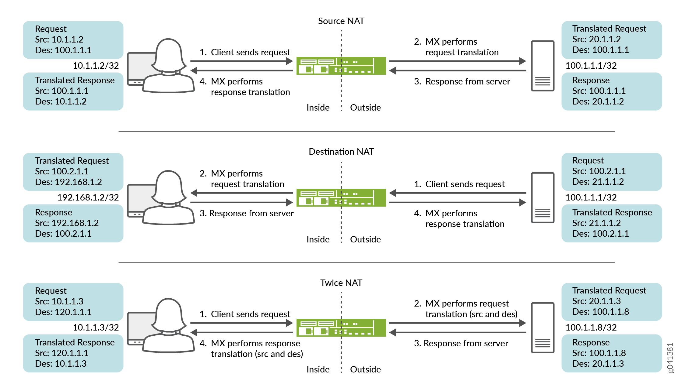
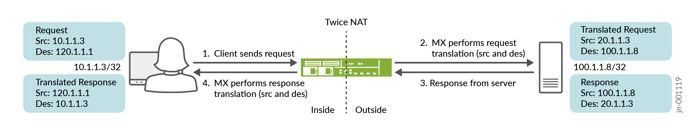
送信元、宛先、および 2 回 NAT のサポート( 図 1 を参照)。インラインNATは、変換タイプ
basic-nat44をサポートしています。Junos OSリリース15.1R1以降、インラインNATもtwice-basic-nat-44をサポートします。 -
ヘアピンのサポート。
インラインNATを設定するには、サービスインターフェイスをタイプ si- (サービスインライン)インターフェイスとして定義します。また、インラインインターフェイス用に十分な帯域幅を確保する必要があります。これにより、NAT に使用するインターフェイスまたはネクストホップ サービス セットの両方を設定できます。 si- インターフェイスは、「仮想サービスPIC」として機能します。
-
静的NATのみサポートされます。ポート変換、ダイナミック NAT、ALG はサポートされていません。そのため、NAT の高度な処理を必要とする SIP や FTP アクティブ モードなどのアプリケーションは機能しません。ステートフルファイアウォール処理、ALGサポート、およびダイナミックポート変換には、MS-MPC、MS-MIC、MS-DPC、またはMS-PICが引き続き必要です。
-
インライン NAT は、パケットのサンプリングやロギングをサポートしていません。
インラインNATのメリット
-
サービスカードが不要
-
サービスカードよりも多くのNATフローをサポート
関連項目
例:インラインネットワークアドレス変換の設定 - インターフェイスベースの方式
この設定例では、インターフェイススタイルのサービスセットを備えた si- (サービスインライン)インターフェイスを使用して、MXシリーズデバイス上でインターフェイスベースのインラインネットワークアドレス変換(NAT)を設定する方法を示しています。
このトピックでは、以下の内容を取り上げます。
要件
この例では、以下のハードウェアおよびソフトウェアコンポーネントを使用しています。
-
モジュラーポートコンセントレータ(MPC)ラインカードを搭載したMXシリーズルーター
-
Junos OSリリース11.4R1以降
概要とトポロジー
Junos OSリリース11.4R1以降、MPCラインカードは、MS-MPCなどの専用サービスカードを必要とせずに一部のサービスを実行できます。インライン サービスは一般に、サービス カードを使用するよりも優れたパフォーマンスを提供しますが、その機能はより基本的なものになる傾向があります。例えば、インラインNATは静的NATのみをサポートします。
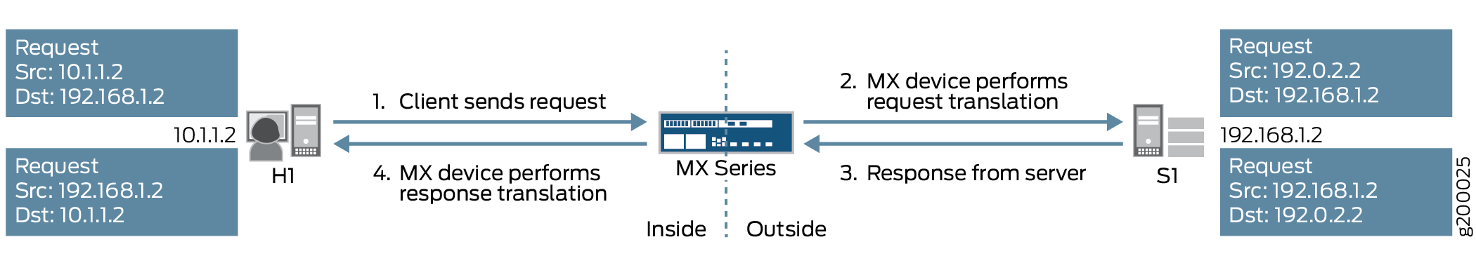
この例では、MPCラインカードを搭載したMXシリーズデバイスが、2つのエンドホスト間を流れるトラフィックにインラインソースNATサービスを提供します。このシナリオのトポロジーを図 2 に示します
 を備えたMXシリーズデバイスを使用したインラインソースNAT
図に示すように、ホストH1はサーバーS1にトラフィックを送信します。MXシリーズデバイスは、ソースNATを実行して、H1の送信元IPアドレスを10.1.1.2から192.0.2.2に変換します。その後、サーバーS1は宛先IPアドレス192.0.2.2を使用してホストH1にリターントラフィックを送信し、MXシリーズデバイスはH1のIPアドレスを10.1.1.2に戻します。
このシナリオでは、以下の設定要素が使用されます。
-
インライン サービス インターフェイス - MPC のパケット転送エンジン上に存在する仮想インターフェイス。サービスにアクセスするために、トラフィックはこれらの
si-(サービスインライン)インターフェイスに出入りします。 -
サービスセット—実行するサービスを定義し、どのインラインインターフェイスがサービスセットとの間でトラフィックを送り込むかを特定します。サービスセットを実装するには、2つの方法があります。
-
インターフェイススタイル—インターフェイスに到着したパケットがインラインサービスを介して転送される、インターフェイスベースの方式。
-
ネクストホップスタイル—ルートベースの方式で、静的ルートを使用して、特定の宛先宛てのパケットをインラインサービスを介して転送します。
この例では、インターフェイススタイルのサービスセットを使用しています。
-
-
NATルール—if-then構造(ファイアウォールフィルターと同様)を使用して一致条件を定義し、一致するトラフィックにアドレス変換を適用します。
-
NATプール—変換のためにNATルールによって使用されるIPアドレスのユーザー定義NATセット。
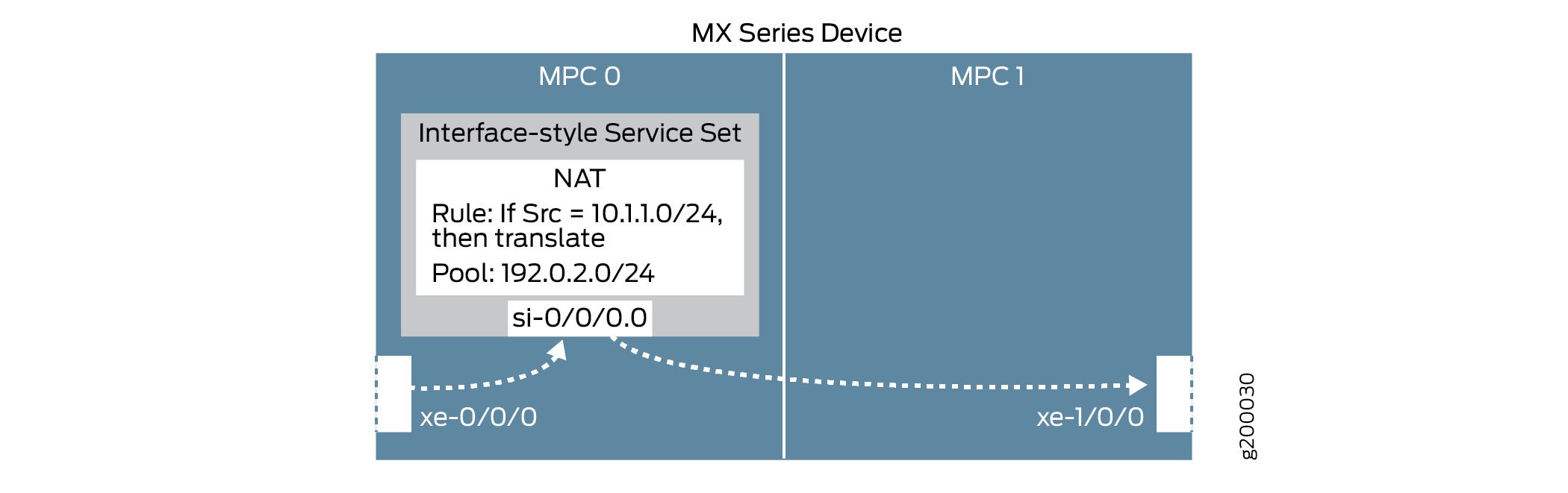
これらの要素は、図3に示すようにまとめられています
インラインネットワークアドレス変換の設定
インターフェイススタイルのサービスセットを使用してインラインNATを設定するには、以下のタスクを実行します。
- CLIクイックコンフィグレーション
- インラインサービスを有効にし、インラインインターフェイスを作成する
- NATルールとプールの設定
- (インターフェイススタイルの)サービスセットを設定します
- 物理インターフェイスの設定
CLIクイックコンフィグレーション
この例をすばやく設定するには、以下のコマンドをコピーしてテキストファイルに貼り付け、改行を削除して、ネットワーク構成に合わせて必要な詳細を変更し、[edit]階層レベルのCLIにコマンドをコピー&ペーストします。
## Enable inline services, create an si- interface, reserve bandwidth ##
set chassis fpc 0 pic 0 inline-services bandwidth 1g
set interfaces si-0/0/0 unit 0 family inet
## Configure a NAT rule and pool ##
set services nat rule SRC-NAT1 match-direction input
set services nat rule SRC-NAT1 term r1 from source-address 10.1.1.0/24
set services nat rule SRC-NAT1 term r1 then translated translation-type basic-nat44
set services nat rule SRC-NAT1 term r1 then translated source-pool p1
set services nat pool p1 address 192.0.2.0/24
## Configure the (interface-style) service set ##
set services service-set INT-STYLE-SS-NAT1 nat-rules SRC-NAT1
set services service-set INT-STYLE-SS-NAT1 interface-service service-interface si-0/0/0.0
## Configure interfaces ##
set interfaces xe-0/0/0 unit 0 family inet address 10.1.1.1/24
set interfaces xe-0/0/0 description INSIDE
set interfaces xe-1/0/0 unit 0 family inet address 192.168.1.1/24
set interfaces xe-1/0/0 description OUTSIDE
set interfaces xe-0/0/0 unit 0 family inet service input service-set INT-STYLE-SS-NAT1
set interfaces xe-0/0/0 unit 0 family inet service output service-set  INT-STYLE-SS-NAT1
インラインサービスを有効にし、インラインインターフェイスを作成する
ステップバイステップの手順
関連するFPCスロットとPICスロットのインラインサービスを有効にし、インラインサービス専用の帯域幅の量を定義します。
ここでのFPCとPIC設定は、
si-インターフェイスを作成し、マッピングします。[edit chassis fpc 0 pic 0] user@MX# set inline-services bandwidth 1g
si-インターフェイスで、NATサービスを必要とするプロトコルファミリーを指定します。注:ここでのFPCとPICの設定は、上記で定義した設定と一致する必要があります。
[edit interfaces si-0/0/0]
user@MX# set unit 0 family inet
NATルールとプールの設定
ステップバイステップの手順
H1のサブネット(10.1.1.0/24)からMXデバイスに到着するトラフィックに一致し、基本的なIPv4 NATを使用して変換し、プール
p1のIPアドレスを使用するNATルールを設定します。[edit services nat] user@MX# set rule SRC-NAT1 match-direction input user@MX# set rule SRC-NAT1 term r1 from source-address 10.1.1.0/24 user@MX# set rule SRC-NAT1 term r1 then translated translation-type basic-nat44 user@MX# set rule SRC-NAT1 term r1 then translated source-pool p1
NATプールを設定します。
[edit services nat]
user@MX# set pool p1 address 192.0.2.0/24
(インターフェイススタイルの)サービスセットを設定します
ステップバイステップの手順
インラインNATサービス(
nat-rules)と上記で定義したインラインインターフェイスを使用するサービスセットを設定します。interface-serviceパラメーターを使用して、これがインターフェイス スタイルのサービス セットであることを指定します。トラフィックは、インラインNATサービスにアクセスするために、
si-インターフェイスに出入りします。[edit services] user@MX# set service-set INT-STYLE-SS-NAT1 nat-rules SRC-NAT1 user@MX# set service-set INT-STYLE-SS-NAT1 interface-service service-interface si-0/0/0.0
物理インターフェイスの設定
ステップバイステップの手順
物理インターフェイスを設定します。
[edit interfaces]
user@MX# set xe-0/0/0 unit 0 family inet address 10.1.1.1/24
user@MX# set xe-0/0/0 description INSIDE
user@MX# set xe-1/0/0 unit 0 family inet address 192.168.1.1/24
user@MX# set xe-1/0/0 description OUTSIDE
「inside」インターフェイスで、トラフィックが上記で定義されたサービスセットを介して送信されることを指定します。
[edit interfaces xe-0/0/0 unit 0]
user@MX# set family inet service input service-set INT-STYLE-SS-NAT1
user@MX# set family inet service output service-set  INT-STYLE-SS-NAT1
結果
chassis {
    fpc 0 {
        pic 0 {
            inline-services {
                bandwidth 1g;
            }
        }
    }
}

services {
    service-set INT-STYLE-SS-NAT1 {
        nat-rules SRC-NAT1;
        interface-service {
            service-interface si-0/0/0.0;
        }
    }
    nat {
        pool p1 {
            address 192.0.2.0/24;
        }
        rule SRC-NAT1 {
            match-direction input;
            term r1 {
                from {
                    source-address {
                        10.1.1.0/24;
                    }
                }
                then {
                    translated {
                        source-pool p1;
                        translation-type {
                            basic-nat44;
                        }
                    }
                }
            }
        }
    }
}

interfaces {
    si-0/0/0 {
        unit 0 {
            family inet;
        }
    }
    xe-0/0/0 {
        description INSIDE;
        unit 0 {
            family inet {
                service {
                    input {
                        service-set INT-STYLE-SS-NAT1;
                    }
                    output {
                        service-set INT-STYLE-SS-NAT1;
                    }
                }
                address 10.1.1.1/24;
            }
        }
    }
    xe-1/0/0 {
        description OUTSIDE;
        unit 0 {
            family inet {
                address 192.168.1.1/24;
            }
        }
    }
}
検証
設定が正常に機能していることを確認します。
ホストH1からサーバーS1への到達可能性の検証
目的
H1とS1の間の到達可能性を検証します。
アクション
ホストH1で、ホストがサーバーS1にpingを実行していることを確認します。
user@H1> ping 192.168.1.2 count 5
PING 192.168.1.2 (192.168.1.2): 56 data bytes
64 bytes from 192.168.1.2: icmp_seq=0 ttl=63 time=0.991 ms
64 bytes from 192.168.1.2: icmp_seq=1 ttl=63 time=14.186 ms
64 bytes from 192.168.1.2: icmp_seq=2 ttl=63 time=3.016 ms
64 bytes from 192.168.1.2: icmp_seq=3 ttl=63 time=3.742 ms
64 bytes from 192.168.1.2: icmp_seq=4 ttl=63 time=4.748 ms

--- 192.168.1.2 ping statistics ---
5 packets transmitted, 5 packets received, 0% packet loss
round-trip min/avg/max/stddev = 0.991/5.337/14.186/4.593 ms
意味
H1は正常にS1に到達できます。
アドレス変換の検証
目的
アドレス変換が正しく機能していることを確認します。
アクション
MXデバイスで、インラインNAT設定の詳細が正しく適用されていることを確認します。
user@MX> show services inline nat pool
Interface: si-0/0/0, Service set: INT-STYLE-SS-NAT1
  NAT pool: p1, Translation type: BASIC NAT44
    Address range: 192.0.2.0-192.0.2.255
    NATed packets: 5, deNATed packets: 5, Errors: 0
サーバーS1で、サーバーがH1のNAT変換された送信元IPアドレス(192.0.2.2)からpingを受信していることを確認します。
以下のコマンドを発行し、H1から再度pingを送信します。
注:この設定では、別のMXデバイスを使用してサーバーS1を表し、インバウンドトラフィックの監視を可能にします。
user@S1> monitor traffic interface xe-1/1/1 no-resolve
verbose output suppressed, use <detail> or <extensive> for full protocol decode
Address resolution is OFF.
Listening on xe-1/1/1, capture size 96 bytes

23:28:28.577377  In IP 192.0.2.2 > 192.168.1.2: ICMP echo request, id 3293, seq 0, length 64
23:28:28.577405 Out IP 192.168.1.2 > 192.0.2.2: ICMP echo reply, id 3293, seq 0, length 64
23:28:29.579253  In IP 192.0.2.2 > 192.168.1.2: ICMP echo request, id 3293, seq 1, length 64
23:28:29.579278 Out IP 192.168.1.2 > 192.0.2.2: ICMP echo reply, id 3293, seq 1, length 64
23:28:30.579275  In IP 192.0.2.2 > 192.168.1.2: ICMP echo request, id 3293, seq 2, length 64
23:28:30.579302 Out IP 192.168.1.2 > 192.0.2.2: ICMP echo reply, id 3293, seq 2, length 64
23:28:31.580279  In IP 192.0.2.2 > 192.168.1.2: ICMP echo request, id 3293, seq 3, length 64
23:28:31.580305 Out IP 192.168.1.2 > 192.0.2.2: ICMP echo reply, id 3293, seq 3, length 64
23:28:32.581266  In IP 192.0.2.2 > 192.168.1.2: ICMP echo request, id 3293, seq 4, length 64
23:28:32.581293 Out IP 192.168.1.2 > 192.0.2.2: ICMP echo reply, id 3293, seq 4, length 64
^C
10 packets received by filter
0 packets dropped by kernel
意味
上記のステップ1では、インラインNATサービスパラメーターとインターフェイススタイルサービスセットが正しく実装されていることを確認します。上記のステップ2では、サーバーS1がNAT変換された送信元IPアドレスからH1のpingを正しく受信していることを確認します。
Twice NATの設定
インターフェイススタイルのサービスセットを使用してTwice NATを設定するには、以下のタスクを実行します。
CLIクイックコンフィグレーション
この例をすばやく設定するには、以下のコマンドをコピーしてテキストファイルに貼り付け、改行を削除して、ネットワーク構成に合わせて必要な詳細を変更し、[edit]階層レベルのCLIにコマンドをコピー&ペーストします。
## Configure a NAT rule and pool ##
set services nat pool dst-pool-p1 address 100.1.1.2/32
set services nat pool dst-pool-p2 address 100.1.1.4/32
set services nat pool src-pool-p2 address 20.0.0.0/8
set services nat allow-overlapping-nat-pools
set services nat rule TWICE_rule_1 match-direction output
set services nat rule TWICE_rule_1 term TWICE_rule_1_term_1 from source-address 10.0.0.0/8
set services nat rule TWICE_rule_1 term TWICE_rule_1_term_1 from destination-address 120.1.1.2/32
set services nat rule TWICE_rule_1 term TWICE_rule_1_term_1 then translated source-pool src-pool-p1
set services nat rule TWICE_rule_1 term TWICE_rule_1_term_1 then translated destination-pool dst-pool-p1
set services nat rule TWICE_rule_1 term TWICE_rule_1_term_1 then translated translation-type twice-basic-nat-44
set services nat rule TWICE_rule_1 term TWICE_rule_1_term_2 from source-address 10.0.0.0/8
set services nat rule TWICE_rule_1 term TWICE_rule_1_term_2 from destination-address 120.1.1.4/32
set services nat rule TWICE_rule_1 term TWICE_rule_1_term_2 then translated source-pool src-pool-p2
set services nat rule TWICE_rule_1 term TWICE_rule_1_term_2 then translated destination-pool dst-pool-p2
set services nat rule TWICE_rule_1 term TWICE_rule_1_term_2 then translated translation-type twice-basic-nat-44
set services nat rule-set TWICE_NAT_RS1 rule TWICE_rule_1
set services service-set TWICE_SS_1 nat-rule-sets TWICE_NAT_RS1
set services service-set TWICE_SS_1 interface-service service-interface si-2/0/0
## Configure interfaces ##
set interfaces si-2/0/0 unit 0 family inet filter input log_filer
set interfaces xe-2/0/0 unit 0 family inet address 10.1.1.251/16
set interfaces xe-2/0/1 unit 0 family inet service input service-set TWICE_SS_1 service-filter TWICE_SF_in
set interfaces xe-2/0/1 unit 0 family inet service output service-set TWICE_SS_1 service-filter TWICE_SF_out
set interfaces xe-2/0/1 unit 0 family inet address 100.1.1.251/16
## Configure firewall filters ##
set firewall family inet service-filter TWICE_SF_in term SF_R1_term_1 from source-address 100.1.1.2/32
set firewall family inet service-filter TWICE_SF_in term SF_R1_term_1 then service
set firewall family inet service-filter TWICE_SF_in term SF_R1_term_2 from source-address 100.1.1.4/32
set firewall family inet service-filter TWICE_SF_in term SF_R1_term_2 then service
set firewall family inet service-filter TWICE_SF_in term default then count non-matching-packets-in
set firewall family inet service-filter TWICE_SF_out term SF_R1_out_term_1 from destination-address 120.1.1.2/32
set firewall family inet service-filter TWICE_SF_out term SF_R1_out_term_1 then service
set firewall family inet service-filter TWICE_SF_out term SF_R1_out_term_2 from destination-address 120.1.1.4/32
set firewall family inet service-filter TWICE_SF_out term SF_R1_out_term_2 then service
set firewall family inet service-filter TWICE_SF_out term default then count non-matching-packets-out
set firewall family inet service-filter TWICE_SF_out term default then skip
(インターフェイススタイルの)サービスセットを設定します
Twice NATサービス(
nat-rules)を使用するサービスセットを設定します。ainterface-serviceパラメーターを使用して、これがインターフェイススタイルのサービスセットであることを指定します。[edit services] user@MX# set service-set TWICE_SS_1 nat-rule-sets TWICE_NAT_RS1 user@MX# set service-set TWICE_SS_1 interface-service service-interface si-2/0/0
物理インターフェイスの設定
ステップバイステップの手順
物理インターフェイスを設定します。
[edit interfaces]
user@MX# set si-2/0/0 unit 0 family inet filter input log_filer
user@MX# set xe-2/0/0 unit 0 family inet address 10.1.1.251/16
user@MX# set xe-2/0/1 unit 0 family inet service input service-set TWICE_SS_1 service-filter TWICE_SF_in
user@MX# set xe-2/0/1 unit 0 family inet service output service-set TWICE_SS_1 service-filter TWICE_SF_out
user@MX# set xe-2/0/1 unit 0 family inet address 100.1.1.251/16
インターフェイスで、トラフィックが上記で定義されたサービスセットを介して送信されることを指定します。
[edit interfaces]
user@MX# set xe-2/0/1 unit 0 family inet service input service-set TWICE_SS_1 service-filter TWICE_SF_in
user@MX# set xe-2/0/1 unit 0 family inet service output service-set TWICE_SS_1 service-filter TWICE_SF_out
ファイアウォールフィルターオプションを設定して、トラフィックを
siインターフェイスに誘導します。[edit firewall] user@MX# set family inet service-filter TWICE_SF_in term SF_R1_term_1 from source-address 100.1.1.2/32 user@MX# set family inet service-filter TWICE_SF_in term SF_R1_term_1 then service user@MX# set family inet service-filter TWICE_SF_in term SF_R1_term_2 from source-address 100.1.1.4/32 user@MX# set family inet service-filter TWICE_SF_in term SF_R1_term_2 then service user@MX# set family inet service-filter TWICE_SF_in term default then count non-matching-packets-in user@MX# set family inet service-filter TWICE_SF_out term SF_R1_out_term_1 from destination-address 120.1.1.2/32 user@MX# set family inet service-filter TWICE_SF_out term SF_R1_out_term_1 then service user@MX# set family inet service-filter TWICE_SF_out term SF_R1_out_term_2 from destination-address 120.1.1.4/32 user@MX# set family inet service-filter TWICE_SF_out term SF_R1_out_term_2 then service user@MX# set family inet service-filter TWICE_SF_out term default then count non-matching-packets-out user@MX# set family inet service-filter TWICE_SF_out term default then skip
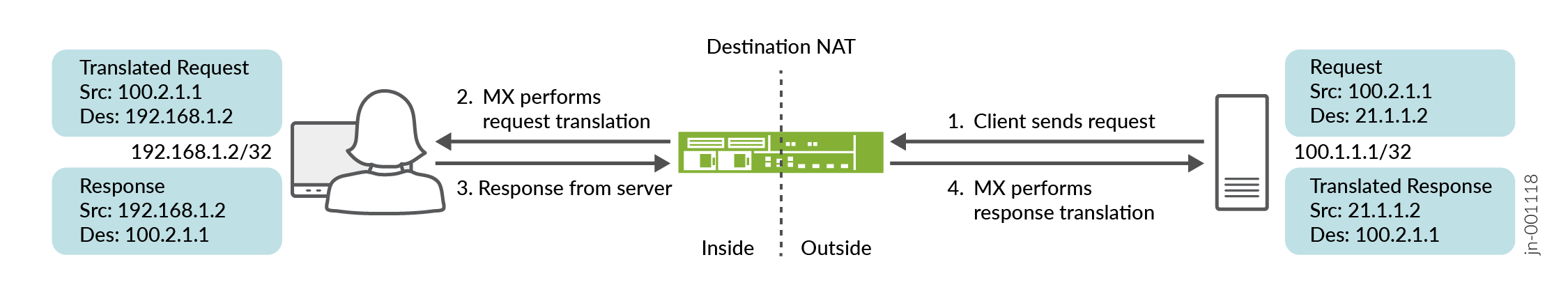
宛先 NAT の設定
インターフェイススタイルのサービスセットを使用して宛先NATを設定するには、以下のタスクを実行します。
CLIクイックコンフィグレーション
この例をすばやく設定するには、以下のコマンドをコピーしてテキストファイルに貼り付け、改行を削除して、ネットワーク構成に合わせて必要な詳細を変更し、[edit]階層レベルのCLIにコマンドをコピー&ペーストします。
## Enable inline services, create an si- interface ##
set chassis fpc 2 pic 0 inline-services
set chassis fpc 2 pic 1 inline-services
set services service-set DANT44_SS_1 nat-rule-sets DNAT44_RS_1
set services service-set DANT44_SS_1 interface-service service-interface si-2/0/0.0
## Configure a NAT rule  ##
set services nat rule DNAT44_rule_1 match-direction output
set services nat rule DNAT44_rule_1 term DNAT44_R1_term_1 from destination-address 21.1.1.2/32
set services nat rule DNAT44_rule_1 term DNAT44_R1_term_1 then translated destination-prefix 192.168.1.2/32
set services nat rule DNAT44_rule_1 term DNAT44_R1_term_1 then translated translation-type dnat-44
set services nat rule-set DNAT44_RS_1 rule DNAT44_rule_1
##  Configure interfaces (and the interface-style) and service filters ##
set interfaces si-2/0/0 unit 0 family inet
set interfaces xe-2/0/0 unit 0 family inet address 100.2.1.2/24
set interfaces xe-2/0/1 unit 0 family inet service input service-set DANT44_SS_1 service-filter SF_in
set interfaces xe-2/0/1 unit 0 family inet service output service-set DANT44_SS_1 service-filter SF_out
set interfaces xe-2/0/1 unit 0 family inet address 192.168.1.251/24
##  Configure the firewall filter options and static route options##
set firewall family inet service-filter SF_in term SF_in_term1 from source-address 192.168.1.2/32
set firewall family inet service-filter SF_in term SF_in_term1 then service
set firewall family inet service-filter SF_out term SF_out_term1 from destination-address 21.1.1.2/32
set firewall family inet service-filter SF_out term SF_out_term1 then service
set routing-options static route 21.1.0.0/16 next-hop 100.2.1.2
インラインサービスを有効にする
関連するFPCスロットとPICスロットのインラインサービスを有効にします。
ここでのFPCとPIC設定は、
si-インターフェイスを作成し、マッピングします。[edit chassis fpc 2 pic 0] user@MX# set inline-services
[edit chassis fpc 2 pic 1]
user@MX# set inline-services
(インターフェイススタイルの)サービスセットを設定します
宛先NATサービス(
nat-rules)を使用するサービスセットを設定します。ainterface-serviceパラメーターを使用して、これがインターフェイススタイルのサービスセットであることを指定します。[edit services service-set] user@MX# set DANT44_SS_1 nat-rule-sets DNAT44_RS_1 user@MX# set DANT44_SS_1 DANT44_SS_1 interface-service service-interface si-2/0/0.0
物理インターフェイスの設定
物理インターフェイスを設定します。
[edit interfaces]
user@MX# set si-2/0/0 unit 0 family inet
user@MX# set xe-2/0/0 unit 0 family inet address 100.2.1.2/24
インターフェイス上で、トラフィックが以前に定義したサービスセットを介して送信されることを指定します。
[edit interfaces]
user@MX# set xe-2/0/1 unit 0 family inet service input service-set DANT44_SS_1 service-filter SF_in
user@MX# set xe-2/0/1 unit 0 family inet service output service-set DANT44_SS_1 service-filter SF_out
user@MX# set interfaces xe-2/0/1 unit 0 family inet address 192.168.1.251/24
ファイアウォールフィルターオプションを設定して、トラフィックを
siインターフェイスに誘導します。[edit firewall] user@MX# set firewall family inet service-filter SF_in term SF_in_term1 from source-address 192.168.1.2/32 user@MX# set firewall family inet service-filter SF_in term SF_in_term1 then service user@MX# set firewall family inet service-filter SF_out term SF_out_term1 from destination-address 21.1.1.2/32 user@MX# set firewall family inet service-filter SF_out term SF_out_term1 then service
スタティックルーティングオプションを設定します。
[edit routing-optipons]
user@MX# set static route 21.1.0.0/16 next-hop 100.2.1.2
例:インラインネットワークアドレス変換の設定 - ルートベース方式
この設定例では、ネクストホップスタイルのサービスセットを備えた si- (サービスインライン)インターフェイスを使用して、MXシリーズデバイス上でルートベースのインラインネットワークアドレス変換(NAT)を設定する方法を示しています。
このトピックでは、以下の内容を取り上げます。
要件
この例では、以下のハードウェアおよびソフトウェアコンポーネントを使用しています。
モジュラーポートコンセントレータ(MPC)ラインカードを搭載したMXシリーズルーター
Junos OSリリース11.4R1以降
概要とトポロジー
Junos OSリリース11.4R1以降、MPCラインカードは、MS-MPCなどの専用サービスカードを必要とせずに一部のサービスを実行できます。インライン サービスは一般に、サービス カードを使用するよりも優れたパフォーマンスを提供しますが、その機能はより基本的なものになる傾向があります。例えば、インラインNATは静的NATのみをサポートします。
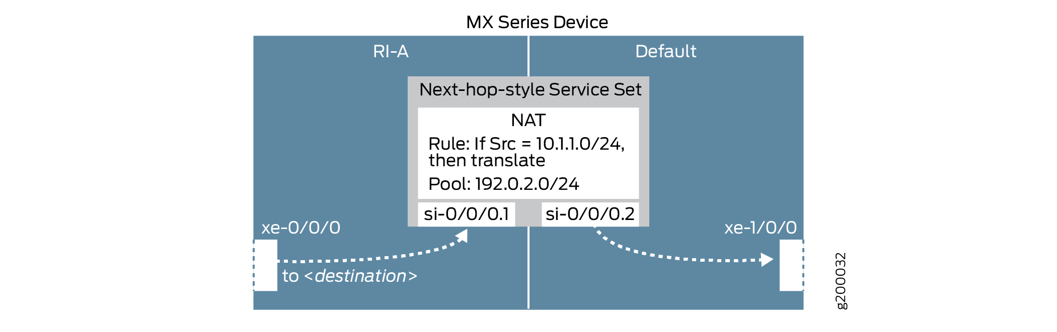
この例では、MPCラインカードを搭載したMXシリーズデバイスが、2つのエンドホスト間を流れるトラフィックにインラインソースNATサービスを提供します。このシナリオのトポロジーを図6に示します
を備えたMXシリーズデバイスを使用したインラインソースNAT
図に示すように、ホストH1はサーバーS1にトラフィックを送信します。MXシリーズデバイスは、ソースNATを実行して、H1の送信元IPアドレスを10.1.1.2から192.0.2.2に変換します。その後、サーバーS1は宛先IPアドレス192.0.2.2を使用してホストH1にリターントラフィックを送信し、MXシリーズデバイスはH1のIPアドレスを10.1.1.2に戻します。
このシナリオでは、以下の設定要素が使用されます。
インライン サービス インターフェイス - MPC のパケット転送エンジン上に存在する仮想インターフェイス。サービスにアクセスするために、トラフィックはこれらの
si-(サービスインライン)インターフェイスに出入りします。サービスセット—実行するサービスを定義し、どのインラインインターフェイスがサービスセットとの間でトラフィックを送り込むかを特定します。サービスセットを実装するには、2つの方法があります。
インターフェイススタイル—インターフェイスに到着したパケットがインラインサービスを介して転送される、インターフェイスベースの方式。
ネクストホップスタイル—ルートベースの方式で、静的ルートを使用して、特定の宛先宛てのパケットをインラインサービスを介して転送します。
この例では、ネクストホップスタイルのサービスセットを使用しています。
NATルール—if-then構造(ファイアウォールフィルターと同様)を使用して一致条件を定義し、一致するトラフィックにアドレス変換を適用します。
NATプール—変換のためにNATルールによって使用されるIPアドレスのユーザー定義NATセット。
ルーティングインスタンス—メイン(デフォルト)ルーティングインスタンスとは別に実行されるルーティングテーブル、インターフェイス、ルーティングプロトコルパラメーターの集合。
ルートベースのインライン NAT は、通常、ルーティング インスタンスが含まれるシナリオで使用されます。
これらの要素は、 図7に示すようにまとめられています。
設定
ネクストホップスタイルのサービスセットを使用してインラインNATを設定するには、以下のタスクを実行します。
- CLIクイックコンフィグレーション
- 物理インターフェイスの設定
- インラインサービスを有効にし、インラインインターフェイスを作成する
- ルーティングインスタンスを設定し、インラインNATサービスを介して送信するトラフィックを特定する
- NATルールとプールの設定
- (ネクストホップスタイルの)サービスセットを設定します
CLIクイックコンフィグレーション
この例をすばやく設定するには、以下のコマンドをコピーしてテキストファイルに貼り付け、改行を削除して、ネットワーク構成に合わせて必要な詳細を変更し、[edit]階層レベルのCLIにコマンドをコピー&ペーストします。
## Configure interfaces ##
set interfaces xe-0/0/0 unit 0 family inet address 10.1.1.1/24
set interfaces xe-0/0/0 description INSIDE
set interfaces xe-1/0/0 unit 0 family inet address 192.168.1.1/24
set interfaces xe-1/0/0 description OUTSIDE
## Enable inline services, create an si- interface, reserve bandwidth ##
set chassis fpc 0 pic 0 inline-services bandwidth 1g
set interfaces si-0/0/0 unit 1 family inet
set interfaces si-0/0/0 unit 1 service-domain inside
set interfaces si-0/0/0 unit 2 family inet
set interfaces si-0/0/0 unit 2 service-domain outside
## Configure routing instance, feed traffic into the inline NAT service ##
set routing-instances RI-A instance-type virtual-router
set routing-instances RI-A interface xe-0/0/0.0
set routing-instances RI-A interface si-0/0/0.1
set routing-instances RI-A routing-options static route 192.168.1.2/32 next-hop si-0/0/0.1
## Configure a NAT rule and pool ##
set services nat rule SRC-NAT1 match-direction input
set services nat rule SRC-NAT1 term r1 from source-address 10.1.1.0/24
set services nat rule SRC-NAT1 term r1 then translated translation-type basic-nat44
set services nat rule SRC-NAT1 term r1 then translated source-pool p1
set services nat pool p1 address 192.0.2.0/24
## Configure the (next-hop-style) service set ##
set services service-set NH-STYLE-SS-NAT1 nat-rules SRC-NAT1
set services service-set NH-STYLE-SS-NAT1 next-hop-service inside-service-interface si-0/0/0.1
set services service-set NH-STYLE-SS-NAT1 next-hop-service outside-service-interface si-0/0/0.2
物理インターフェイスの設定
ステップバイステップの手順
物理インターフェイスを設定します。
[edit interfaces]
user@MX# set xe-0/0/0 unit 0 family inet address 10.1.1.1/24
user@MX# set xe-0/0/0 description INSIDE
user@MX# set xe-1/0/0 unit 0 family inet address 192.168.1.1/24
user@MX# set xe-1/0/0 description OUTSIDE
インラインサービスを有効にし、インラインインターフェイスを作成する
ステップバイステップの手順
関連するFPCスロットとPICスロットのインラインサービスを有効にし、インラインサービス専用の帯域幅の量を定義します。
ここでのFPCとPIC設定は、
si-インターフェイスを作成し、マッピングします。[edit chassis fpc 0 pic 0] user@MX# set inline-services bandwidth 1g
si-インターフェイスで、2つの論理ユニットを作成します。ユニットごとに、NATサービスを必要とするプロトコルファミリー(または複数のファミリー)と、サービスドメインの「内部」または「外部」インターフェイスを指定します。注:ここでのFPCとPICの設定は、上記で定義した設定と一致する必要があります。
[edit interfaces si-0/0/0]
user@MX# set unit 1 family inet
user@MX# set unit 1 service-domain inside
user@MX# set unit 2 family inet
user@MX# set unit 2 service-domain outside
ルーティングインスタンスを設定し、インラインNATサービスを介して送信するトラフィックを特定する
ステップバイステップの手順
「ínside」の物理インターフェイスと
si-インターフェイス、およびsi-インターフェイスを介してインラインNATサービスに転送するトラフィックを特定する静的ルートを含むルーティングインスタンスを設定します。わかりやすくするために、ここで使用する静的ルートは、単にサーバーS1を識別します。
[edit routing-instances]
user@MX# set RI-A instance-type virtual-router
user@MX# set RI-A interface xe-0/0/0.0
user@MX# set RI-A interface si-0/0/0.1
user@MX# set RI-A routing-options static route 192.168.1.2/32 next-hop si-0/0/0.1
NATルールとプールの設定
ステップバイステップの手順
H1のサブネット(10.1.1.0/24)からMXデバイスに到着するトラフィックに一致し、基本的なIPv4 NATを使用して変換し、プール
p1のIPアドレスを使用するNATルールを設定します。[edit services nat] user@MX# set rule SRC-NAT1 match-direction input user@MX# set rule SRC-NAT1 term r1 from source-address 10.1.1.0/24 user@MX# set rule SRC-NAT1 term r1 then translated translation-type basic-nat44 user@MX# set rule SRC-NAT1 term r1 then translated source-pool p1
NATプールを設定します。
[edit services nat]
user@MX# set pool p1 address 192.0.2.0/24
(ネクストホップスタイルの)サービスセットを設定します
ステップバイステップの手順
インラインNATサービス(
nat-rules)、および上記で定義したインラインインターフェイスを使用するサービスセットを設定します。next-hop-serviceパラメータを使用して、これがネクストホップスタイルのサービスセットであることを指定し、上記の設定に基づいてsi-インターフェイスを「inside」と「outside」に割り当てます。トラフィックは、インラインNATサービスにアクセスするために、
si-インターフェイスに出入りします。[edit services] user@MX# set service-set NH-STYLE-SS-NAT1 nat-rules SRC-NAT1 user@MX# set service-set NH-STYLE-SS-NAT1 next-hop-service inside-service-interface si-0/0/0.1 user@MX# set service-set NH-STYLE-SS-NAT1 next-hop-service outside-service-interface si-0/0/0.2
結果
chassis {
    fpc 0 {
        pic 0 {
            inline-services {
                bandwidth 1g;
            }
        }
    }
}

services {
    service-set NH-STYLE-SS-NAT1 {
        nat-rules SRC-NAT1;
        next-hop-service {
            inside-service-interface si-0/0/0.1;
            outside-service-interface si-0/0/0.2;
        }
    }
    nat {
        pool p1 {
            address 192.0.2.0/24;
        }
        rule SRC-NAT1 {
            match-direction input;
            term r1 {
                from {
                    source-address {
                        10.1.1.0/24;
                    }
                }
                then {
                    translated {
                        source-pool p1;
                        translation-type {
                            basic-nat44;
                        }
                    }
                }
            }
        }
    }
}

interfaces {
    si-0/0/0 {
       unit 1 {
            family inet;
            service-domain inside;
        }
        unit 2 {
            family inet;
            service-domain outside;
        }
    }
    xe-0/0/0 {
        description INSIDE;
        unit 0 {
            family inet {
                  address 10.1.1.1/24;
            }
        }
    }
    xe-1/0/0 {
        description OUTSIDE;
        unit 0 {
            family inet {
                address 192.168.1.1/24;
            }
        }
    }
}

routing-instances {
    RI-A {
        instance-type virtual-router;
        interface xe-0/0/0.0;
        interface si-0/0/0.1;
        routing-options {
            static {
                route 192.168.1.2/32 next-hop si-0/0/0.1;
            }
        }
    }
}
検証
設定が正常に機能していることを確認します。
ホストH1からサーバーS1への到達可能性の検証
目的
H1とS1の間の到達可能性を検証します。
アクション
ホストH1で、ホストがサーバーS1にpingを実行していることを確認します。
user@H1> ping 192.168.1.2 count 5
PING 192.168.1.2 (192.168.1.2): 56 data bytes
64 bytes from 192.168.1.2: icmp_seq=0 ttl=63 time=0.926 ms
64 bytes from 192.168.1.2: icmp_seq=1 ttl=63 time=0.859 ms
64 bytes from 192.168.1.2: icmp_seq=2 ttl=63 time=0.853 ms
64 bytes from 192.168.1.2: icmp_seq=3 ttl=63 time=0.825 ms
64 bytes from 192.168.1.2: icmp_seq=4 ttl=63 time=0.930 ms

--- 192.168.1.2 ping statistics ---
5 packets transmitted, 5 packets received, 0% packet loss
round-trip min/avg/max/stddev = 0.825/0.879/0.930/0.042 ms
意味
H1は正常にS1に到達できます。
アドレス変換の検証
目的
アドレス変換が正しく機能していることを確認します。
アクション
MXデバイスで、インラインNAT設定の詳細が正しく適用されていることを確認します。
user@MX> show services inline nat pool
Interface: si-0/0/0, Service set: NH-STYLE-SS-NAT1
  NAT pool: p1, Translation type: BASIC NAT44
    Address range: 192.0.2.0-192.0.2.255
    NATed packets: 5, deNATed packets: 5, Errors: 0, Skipped packets: 0
サーバーS1で、サーバーがH1のNAT変換された送信元IPアドレス(192.0.2.2)からpingを受信していることを確認します。
以下のコマンドを発行し、H1から再度pingを送信します。
注:この設定では、別のMXデバイスを使用してサーバーS1を表し、インバウンドトラフィックの監視を可能にします。
user@S1> monitor traffic interface xe-1/1/1 no-resolve
verbose output suppressed, use <detail> or <extensive> for full protocol decode
Address resolution is OFF.
Listening on xe-1/1/1, capture size 96 bytes

20:19:36.182690  In IP 192.0.2.2 > 192.168.1.2: ICMP echo request, id 4436, seq 0, length 64
20:19:36.182719 Out IP 192.168.1.2 > 192.0.2.2: ICMP echo reply, id 4436, seq 0, length 64
20:19:37.182918  In IP 192.0.2.2 > 192.168.1.2: ICMP echo request, id 4436, seq 1, length 64
20:19:37.182945 Out IP 192.168.1.2 > 192.0.2.2: ICMP echo reply, id 4436, seq 1, length 64
20:19:38.183914  In IP 192.0.2.2 > 192.168.1.2: ICMP echo request, id 4436, seq 2, length 64
20:19:38.183940 Out IP 192.168.1.2 > 192.0.2.2: ICMP echo reply, id 4436, seq 2, length 64
20:19:39.184872  In IP 192.0.2.2 > 192.168.1.2: ICMP echo request, id 4436, seq 3, length 64
20:19:39.184896 Out IP 192.168.1.2 > 192.0.2.2: ICMP echo reply, id 4436, seq 3, length 64
20:19:40.185882  In IP 192.0.2.2 > 192.168.1.2: ICMP echo request, id 4436, seq 4, length 64
20:19:40.185907 Out IP 192.168.1.2 > 192.0.2.2: ICMP echo reply, id 4436, seq 4, length 64
^C
10 packets received by filter
0 packets dropped by kernel
意味
上記のステップ1では、インラインNATサービスパラメーターとネクストホップスタイルサービスセットが正しく実装されていることを確認します。上記のステップ2では、サーバーS1がNAT変換された送信元IPアドレスからH1のpingを正しく受信していることを確認します。
変更履歴テーブル
サポートされる機能は、使用しているプラットフォームとリリースによって決まります。 機能エクスプローラー を使用して、機能がお使いのプラットフォームでサポートされているかどうかを確認します。
twice-basic-nat-44をサポートします