パケットベース転送
SRXシリーズファイアウォールは、パケットモードとフローモードの2種類のモードで動作します。フローモードでは、SRXはトラフィックの状態またはセッションを分析してすべてのトラフィックを処理します。これは、トラフィックのステートフル処理とも呼ばれます。パケットモードでは、SRXはパケットごとにトラフィックを処理します。これは、トラフィックのステートレス処理とも呼ばれます。
パケットベース処理について
Junos OSを実行しているジュニパーネットワークスデバイスに出入りするパケットは、パケットベース処理を受けることができます。パケットベース(ステートレス)パケット処理では、パケットを個別に処理します。各パケットは、治療のために個別に評価されます。ステートレスパケットベースの転送は、フローや状態情報に関係なく、パケットごとに実行されます。各パケットは、治療のために個別に評価されます。
図1は、パケットベース転送のトラフィックフローを示しています。
 のトラフィックフロー
パケットがデバイスに入ると、分類子、フィルター、およびポリサーが適用されます。次に、パケットのエグレスインターフェイスがルートルックアップによって決定されます。パケットのegressインターフェイスが見つかると、フィルターが適用され、パケットがegressインターフェイスに送信され、そこでキューに入れられ、送信がスケジュールされます。
パケットベースの転送では、特定の接続に属する前後のパケットに関する情報は必要なく、トラフィックの許可または拒否の決定はパケット固有です。このアーキテクチャには、個々のフローや状態を追跡せずにパケットを転送するため、大規模な拡張性という利点があります。
選択的ステートレスパケットベースサービスについて
選択的なステートレスパケットベースサービスにより、フローベースとパケットベースの両方の転送をシステム上で同時に使用できます。ACL(アクセスコントロールリスト)とも呼ばれるステートレスファイアウォールフィルターを使用することで、ステートフルフローベースの転送を回避するために、パケットベースのステートレス転送を必要とするトラフィックを選択的に誘導することができます。そのように指示されていないトラフィックは、デフォルトのフローベースの転送パスに従います。フローベース転送をバイパスすることは、フローセッションのスケーリングの制約を明示的に回避したいトラフィックに有効です。
デフォルトでは、Junos OSを実行しているジュニパーネットワークスセキュリティデバイスはフローベースの転送を使用します。選択的ステートレスパケットベースサービスでは、入力フィルターの条件に基づいて、選択したトラフィックに対してパケットベースの処理のみを提供するようにデバイスを設定できます。その他のトラフィックは、フローベースの転送のために処理されます。フローベース転送をバイパスすることは、セッションスケーリングの制約やセッション作成およびメンテナンスコストを回避したい導入環境に有効です。
選択的なステートレスパケットベース処理のためにデバイスを設定する場合、システムに入るパケットは特定の条件によって異なる方法で処理されます。
パケットが入力フィルターの条件で指定された一致条件を満たす場合、パケット モードとしてマークされ、設定されたすべてのパケット モード機能が適用されます。フローベースのセキュリティ機能は適用されません。それはそれらを迂回します。
パケットにパケットモードのフラグが付けられていない場合、通常の処理が行われます。このトラフィックには、MPLS を除くすべてのサービスに適用できます。
図2 は、フローベース処理をバイパスした選択的なステートレスパケットベースサービスによるトラフィックフローを示しています。
パケットがインターフェイスに着信すると、インターフェイスに設定された入力パケットフィルターが適用されます。
パケットが ファイアウォールフィルターで指定された条件に一致する場合、
packet-modeアクション修飾子がパケットに設定されます。パケットモードアクション修飾子は、パケットキーバッファのビットフィールドを更新します。このビットフィールドは、フローベースの転送をバイパスする必要があるかどうかを判断するために使用されます。その結果、パケットモードアクション修飾子を持つパケットは、フローベースの転送を完全にバイパスします。パケットのエグレスインターフェイスは、ルートルックアップによって決定されます。パケットのegressインターフェイスが見つかると、フィルターが適用され、パケットがegressインターフェイスに送信され、そこでキューに入れられ、送信がスケジュールされます。パケットがこのフィルター条件で指定された条件に一致しない場合、フィルターで設定された他の条件に対して評価されます。すべての用語が評価された後、パケットがフィルター内の用語に一致しない場合、パケットはサイレントに破棄されます。パケットが破棄されないようにするには、すべてのパケットを受け入れるアクションを指定する条件をフィルターに設定します。
定義済みのステートレス サービスのセットは、選択されたステートレス パケットベース サービスで利用できます。
IPv4/IPv6ルーティング(ユニキャストおよびマルチキャストプロトコル)
サービスクラス (CoS)
リンクのフラグメント化およびインターリーブ(LFI)
一般的なルーティングカプセル化(GRE)
レイヤー2スイッチング
MPLS(MPLS)
ステートレスファイアウォールフィルター
CRTP(Compressed Real-Time Transport Protocol)
MPLSサービスを必要とするトラフィックはパケットモードで処理する必要がありますが、状況によっては、ステートフルインスペクション、NAT、IPsecなど、フローモードでのみ提供できる特定のサービスをこのトラフィックに同時に適用する必要がある場合があります。フローモードとパケットモードの両方でトラフィックを処理するようにシステムに指示するには、トンネルインターフェイスを介して接続された複数のルーティングインスタンスを設定する必要があります。一方のルーティングインスタンスはフローモードでパケットを処理するように設定し、もう一方のルーティングインスタンスはパケットモードでパケットを処理するように設定する必要があります。トンネルインターフェイスを使用してルーティングインスタンスを接続すると、それらのルーティングインスタンス間のトラフィックが再び転送パスに注入され、その後別の転送方法を使用して再処理することができます。
選択的ステートレスパケットベースサービス設定の概要
この機能は、SRX300、SRX320、SRX340、SRX345、vSRX仮想ファイアウォールデバイスでサポートされています。アクセスコントロールリスト(ACL)とも呼ばれるステートレスファイアウォールフィルターを使用して、選択的なステートレスパケットベースサービスを設定します。ファイアウォールフィルターで一致条件を指定し、アクションを指定するために packet-mode アクション修飾子を設定することで、パケットベース転送のトラフィックを分類します。一致条件とアクションが定義されると、ファイアウォールフィルターが関連するインターフェイスに適用されます。
ファイアウォールフィルターを設定するには:
パケットがインターフェイスに着信すると、インターフェイスに設定された入力パケットフィルターが適用されます。パケットが指定された条件に一致し、アクション packet-mode 設定されている場合、パケットはフローベース転送を完全にバイパスします。
フィルターを設定する際は、ファイアウォールフィルター内の用語の順序に注意してください。パケットは、設定に記載されている順番に各条件に対してテストされます。最初の一致条件が見つかった場合、その条件に関連付けられたアクションがパケットに適用され、 next term アクション修飾子が含まれていない限り、ファイアウォールフィルターの評価は終了します。 next term アクションが含まれている場合、一致するパケットはファイアウォールフィルター内の次の条件に対して評価されます。それ以外の場合、一致するパケットはファイアウォールフィルター内の後続の条件に対して評価されません。
選択的なステートレスパケットベースサービス用にファイアウォールフィルターを設定する場合:
不要なパケットドロップを回避するために、フローをバイパスする必要があるトラフィックを正確に特定します。
パケットベースのフローパスに関与するすべてのインターフェイスに、パケットモードアクションを持つファイアウォールフィルターを適用してください。
フローベース転送を使用するようにホストバウンドTCPトラフィックを必ず設定してください。
packet-modeアクション修飾子を含むファイアウォールフィルター条件の一致条件を指定する場合は、このトラフィックを除外します。フローをバイパスするように設定されたホストバウンドのTCPトラフィックはすべて破棄されます。非同期フローモード処理は、選択的なステートレスパケットベースサービスではサポートされていません。packet-modeアクション修飾子で入力パケットフィルター(出力ではありません)を設定します。
ネストされたファイアウォールフィルター(別のフィルターの条件内でフィルターを設定する)は、選択的なステートレスパケットベースサービスではサポートされていません。
選択的なステートレスパケットベースサービスを設定できる一般的な導入シナリオを以下に示します。
エンドツーエンドの転送がパケットベースであるイントラネットトラフィックなど、プライベートLANとWANインターフェイス間のトラフィックフロー
プライベートLANとあまり安全でないWANインターフェイス間のトラフィックフロー。トラフィックはパケットベースとフローベースの転送を使用して、それぞれセキュアなトラフィックとあまり安全でないトラフィックに
プライベートLANとWANインターフェイス間のトラフィックフローは、プライベートWANリンクがダウンしているときにフローベースのIPsec WANにフェイルオーバーします。
フローベースの LAN からパケットベースの MPLS WAN へのトラフィックフロー
例:エンドツーエンドのパケットベース転送のための選択的ステートレスパケットベースサービスの設定
この例では、エンドツーエンドのパケットベース転送用に、選択的なステートレスパケットベースサービスを設定する方法を示しています。この機能は、SRX300、SRX320、SRX340、SRX345、vSRX仮想ファイアウォールデバイスでサポートされています
要件
始める前に:
-
ステートレスファイアウォールフィルターの設定方法を理解します。
-
基本的な接続性を確立します。.
概要
この例では、各デバイス上のインターフェイスのIPアドレスを設定します。R0の場合は10.1.1.2 / 24です。R1の場合は、10.1.1.1/24、10.2.1.1/24、203.0.113.1/30です。R2の場合は203.0.113.2/30です。R3の場合は10.2.1.2/24です。スタティックルートを作成し、デバイスのネクストホップアドレスを関連付けるには、R0は10.1.1.2、R1は198.51.100.2、R2は203.0.113.1、R3は10.2.1.1です。
次に、デバイスR1でuntrustというゾーンを設定し、インターフェイスge-0/0/3に割り当てます。また、trustと呼ばれるゾーンを作成し、インターフェイスge-0/0/1とge-0/0/2を割り当てます。trustゾーンとuntrustゾーンを設定して、サポートされているすべてのアプリケーションサービスをインバウンドサービスとして許可します。送信元アドレス、宛先アドレス、アプリケーションからのトラフィックがゾーン間を通過できるようにします。
次に、ファイアウォールフィルターbypass-flow-filterを作成し、内部インターフェイスge-0/0/1とge-0/0/2間のトラフィックに一致し、パケットモードアクション修飾子を含む用語bypass-flow-term-1とbypass-flow-term-2を定義します。条件accept-restを定義して、残りのすべてのトラフィックを受け入れます。最後に、ファイアウォールフィルターbypass-flow-filterを内部インターフェイスge-0/0/1およびge-0/0/2(外部インターフェイスにはない)に適用します。その結果、すべての内部トラフィックはフローベース転送をバイパスし、インターネットとの間のトラフィックはフローベース転送をバイパスしません。
図3は、この例で使用されているネットワークトポロジーを示しています。
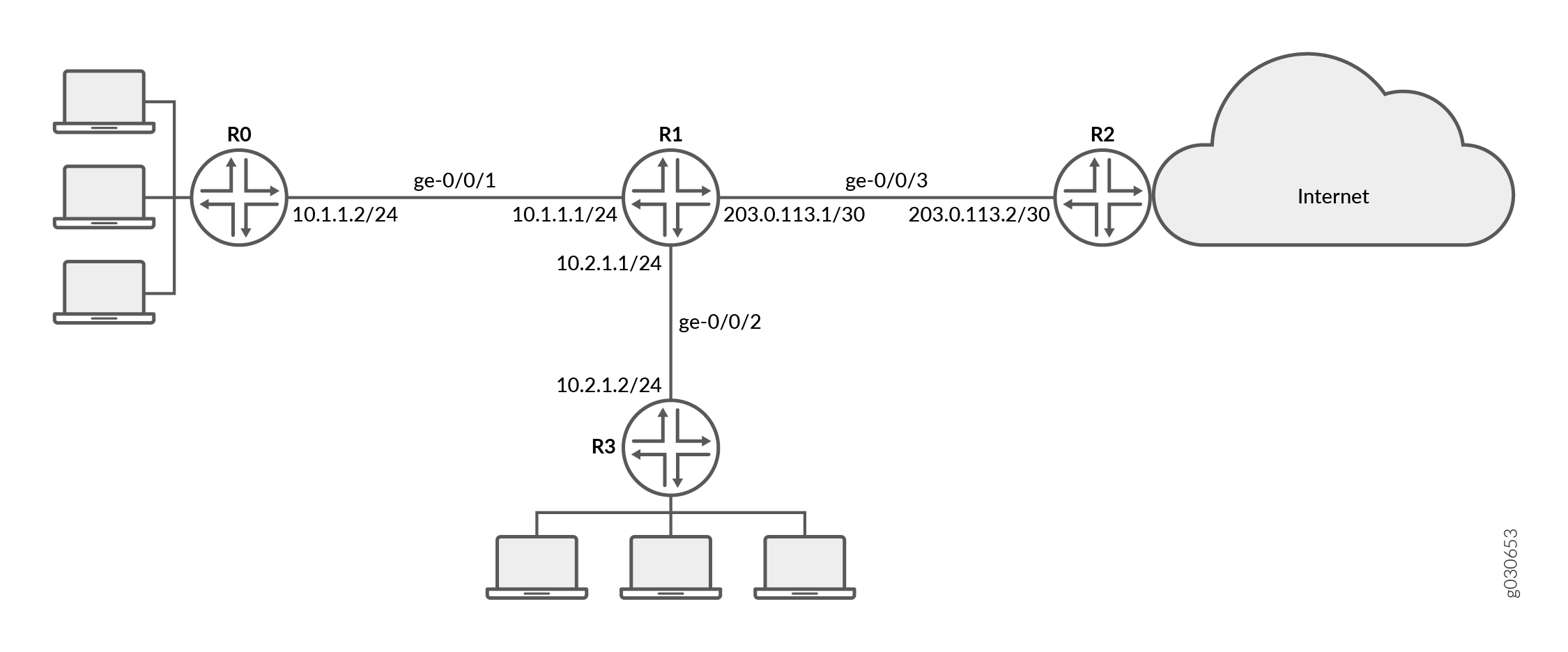
社内の支社は、プライベートWANを介して相互に接続されています。この内部トラフィックでは、セキュリティが問題にならないため、パケット転送が必要です。したがって、このトラフィックでは、フローベースの転送をバイパスするように、選択的なステートレスパケットベースサービスを設定することにしました。インターネットとの間の残りのトラフィックは、フローベースの転送を使用します。
設定
手順
CLIクイックコンフィグレーション
この例をすばやく設定するには、以下のコマンドをコピーしてテキストファイルに貼り付け、改行を削除して、ネットワーク設定に一致させる必要がある詳細を変更し、コマンドを [edit] 階層レベルのCLIにコピーアンドペーストして、設定モードから commit を入力します。
{device R0}
[edit]
set interfaces ge-0/0/1 description "Internal 1" unit 0 family inet address 10.1.1.2/24
set routing-options static route 0.0.0.0/0 next-hop 10.1.1.1
{device R1}
set interfaces ge-0/0/1 description "Internal 1" unit 0 family inet address 10.1.1.1/24
set interfaces ge-0/0/2 description "Internal 2" unit 0 family inet address 10.2.1.1/24
set interfaces ge-0/0/3 description "Internet" unit 0 family inet address 203.0.113.1/30
set routing-options static route 0.0.0.0/0 next-hop 203.0.113.2
set security zones security-zone untrust interfaces ge-0/0/3
set security zones security-zone trust interfaces ge-0/0/1
set security zones security-zone trust interfaces ge-0/0/2
set security zones security-zone trust host-inbound-traffic system-services all
set security zones security-zone untrust host-inbound-traffic system-services all
set security policies from-zone trust to-zone untrust policy Internet-traffic match source-address any destination-address any application any
set security policies from-zone trust to-zone untrust policy Internet-traffic then permit
set security policies from-zone untrust to-zone trust policy Incoming-traffic match source-address any destination-address any application any
set security policies from-zone untrust to-zone trust policy Incoming-traffic then permit
set security policies from-zone trust to-zone trust policy Intrazone-traffic match source-address any destination-address any application any
set security policies from-zone trust to-zone trust policy Intrazone-traffic then permit
set firewall family inet filter bypass-flow-filter term bypass-flow-term-1 from source-address 10.1.1.0/24
set firewall family inet filter bypass-flow-filter term bypass-flow-term–1 from destination-address 10.2.1.0/24
set firewall family inet filter bypass-flow-filter term bypass-flow-term-1 then packet-mode
set firewall family inet filter bypass-flow-filter term bypass-flow-term-2 from source-address 10.2.1.0/24
set firewall family inet filter bypass-flow-filter term bypass-flow-term-2 from destination-address 10.1.1.0/24
set firewall family inet filter bypass-flow-filter term bypass-flow-term-2 then packet-mode
set firewall family inet filter bypass-flow-filter term accept-rest then accept
set interfaces ge-0/0/1 description "Internal 1" unit 0 family inet filter input bypass-flow-filer
set interfaces ge-0/0/2 description "Internal 2" unit 0 family inet filter input bypass-flow-filer
{device R2}
set interfaces ge-0/0/3 description "Internet" unit 0 family inet address 10.1.1.2/30
set routing-options static route 0.0.0.0/0 next-hop 10.1.1.1
{device R3}
[edit]
set interfaces ge-0/0/2 description "Internal 2" unit 0 family inet address 10.2.1.2/24
set routing-options static route 0.0.0.0/0 next-hop 10.2.1.1
ステップバイステップの手順
次の例では、設定階層のさまざまなレベルに移動する必要があります。その方法の詳細については、『CLIユーザーガイド』の「構成モードでのCLIエディターの使用」を参照してください。
エンドツーエンドのパケットベース転送用に、選択的なステートレスパケットベースサービスを設定するには:
-
デバイスR0、R1、R2、およびR3上のインターフェイスのIPアドレスを設定します。
{device R0} [edit] user@host#set interfaces ge-0/0/1 description "Internal 1" unit 0 family inet address 10.1.1.2/24{device R1} [edit] user@host#set interfaces ge-0/0/1 description "Internal 1" unit 0 family inet address 10.1.1.1/24user@host#set interfaces ge-0/0/2 description "Internal 2" unit 0 family inet address 10.2.1.1/24user@host#set interfaces ge-0/0/3 description "Internet" unit 0 family inet address 203.0.113.1/30{device R2} [edit] user@host#set interfaces ge-0/0/3 description "Internet" unit 0 family inet address 203.0.113.1/30{device R3} [edit] user@host#set interfaces ge-0/0/2 description "Internal 2" unit 0 family inet address 10.2.1.2/24 -
静的ルートを作成し、デバイスR0、R1、R2、R3に適切なネクストホップアドレスを関連付けます。
{device R0} [edit] user@host#set routing-options static route 0.0.0.0/0 next-hop 10.1.1.1{device R1} [edit] user@host#set routing-options static route 0.0.0.0/0 next-hop 203.0.113.1{device R2} [edit] user@host#set routing-options static route 0.0.0.0/0 next-hop 203.0.113.2{device R3} [edit] user@host#set routing-options static route 0.0.0.0/0 next-hop 10.2.1.1 -
セキュリティゾーンを設定し、インターフェイスを割り当てます。
{device R1} [edit] user@host#set security zones security-zone untrust interfaces ge-0/0/3user@host#set security zones security-zone trust interfaces ge-0/0/1user@host#set security zones security-zone trust interfaces ge-0/0/2 -
ゾーンのアプリケーションサービスを設定します。
{device R1} [edit] user@host#set security zones security-zone trust host-inbound-traffic system-services alluser@host#set security zones security-zone untrust host-inbound-traffic system-services all -
セキュリティポリシーを設定する
{device R1} [edit] user@host#set security policies from-zone trust to-zone untrust policy Internet-traffic match source-address any destination-address any application anyuser@host#set security policies from-zone trust to-zone untrust policy Internet-traffic then permituser@host#set security policies from-zone untrust to-zone trust policy Incoming-traffic match source-address any destination-address any application anyuser@host#set security policies from-zone untrust to-zone trust policy Incoming-traffic then permituser@host#set security policies from-zone trust to-zone trust policy Intrazone-traffic match source-address any destination-address any application anyuser@host#set security policies from-zone trust to-zone trust policy Intrazone-traffic then permit -
ファイアウォールフィルターを作成し、すべてのパケットベースの転送トラフィックの条件を定義します。
{device R1} [edit] user@host#set firewall family inet filter bypass-flow-filter term bypass-flow-term-1 from source-address 10.1.1.0/24user@host#set firewall family inet filter bypass-flow-filter term bypass-flow-term–1 from destination-address 10.2.1.0/24user@host#set firewall family inet filter bypass-flow-filter term bypass-flow-term-1 then packet-modeuser@host#set firewall family inet filter bypass-flow-filter term bypass-flow-term-2 from source-address 10.2.1.0/24user@host#set firewall family inet filter bypass-flow-filter term bypass-flow-term-2 from destination-address 10.1.1.0/24user@host#set firewall family inet filter bypass-flow-filter term bypass-flow-term-2 then packet-mode -
残りのトラフィックに別の条件を指定します。
{device R1} [edit] user@host#set firewall family inet filter bypass-flow-filter term accept-rest then accept -
ファイアウォールフィルターを関連するインターフェイスに適用します。
{device R1} [edit] user@host#set interfaces ge-0/0/1 description "Internal 1" unit 0 family inet filter input bypass-flow-fileruser@host#set interfaces ge-0/0/2 description "Internal 2" unit 0 family inet filter input bypass-flow-filer
結果
設定モードから、 show interfaces、 show routing-options、 show firewall コマンドを入力して設定を確認します。出力に意図した設定が表示されない場合は、この例の設定手順を繰り返して修正します。
{device R0}
[edit]
user@host# show interfaces
ge-0/0/1 {
    description “Internal 1”
    unit 0 {
        family inet {
            address 10.1.1.2/24
        }
    }
}
{device R0}
[edit]
user@host# show routing-options
static {
    route 0.0.0.0/0 next-hop 10.1.1.1;
}
{device R2}
[edit]
user@host# show interfaces
ge-0/0/3 {
    description “Internet”
    unit 0 {
        family inet {
            address 203.0.113.2/30;
        }
    }
}
{device R2}
[edit]
user@host# show routing-options
static {
    route 0.0.0.0/0 next-hop 203.0.113.1;
}
{device R3}
[edit]
user@host# show interfaces
ge-0/0/2 {
    description “Internal 2”
    unit 0 {
        family inet {
            address 10.2.1.2/24;
        }
    }
}
{device R3}
user@host# show routing-options
static {
    route 0.0.0.0/0 next-hop 10.2.1.1;
}
{device R1}
[edit]
user@host# show interfaces
ge-0/0/1 {
    description “internal 1”
    unit 0 {
        family inet {
            filter {
                input bypass-flow-filter;
                }
            address 10.1.1.1/24;
        }
    }
}
ge-0/0/2 {
    description “Internal 2”
    unit 0 {
        family inet {
            filter {
                input bypass-flow-filter;
                }
            address 10.2.1.1/24;
        }
    }
}
ge-0/0/3 {
    description “Internet”
    unit 0 {
        family inet {
            address 203.0.113.1/30;
        }
    }
}
{device R1}
[edit]
user@host# show routing-options
static {
    route 0.0.0.0/0 next-hop 203.0.113.1;
}
{device R1}
[edit]
user@host# show firewall
family inet {
    filter bypass-flow-filter {
        term bypass-flow-term-1 {
            from {
                source-address {
                    10.1.1.0/24;
                }
                destination-address {
                    10.2.1.0/24;
                }
            }
            then packet-mode;
        }
        term bypass-flow-term-2 {
            from {
                source-address {
                    10.2.1.0/24;
                }
                destination-address {
                    10.1.1.0/24;
                }
            }
            then packet-mode;
        }
        term accept-rest {
            then accept;
        }
    }
}
デバイスの設定が完了したら、設定モードから commit を入力します。
検証
設定が正常に機能していることを確認します。
エンドツーエンドのパケットベース設定の検証
目的
選択的なステートレスパケットベースサービスが設定されていることを確認します。
アクション
設定モードから、 show interfaces、 show routing-options、 show security zones、 show security policies、および show firewall コマンドを入力します。
出力が、ファイアウォールフィルター、インターフェイス、ポリシーの意図した設定を示していることを確認します。
パケットをテストする順序で用語が表示されていることを確認します。 insert コマンドを使用して、ファイアウォールフィルター内で用語を移動できます。
イントラネットトラフィックでのセッション確立の確認
目的
トラフィックがイントラネット内のインターフェイスに送信されるときに、セッションが確立されていることを確認します。
アクション
セッションが確立されていることを確認するには、以下のタスクを実行します。
-
デバイス
R1で、動作モードclear security flow session allコマンドを入力して、既存のセキュリティフローセッションをすべてクリアします。 -
デバイス
R0で、動作モードpingコマンドを入力して、デバイスR3にトラフィックを送信します。 -
デバイス
R1で、デバイスからR1経由でR3にトラフィックR0転送されている場合、コマンドshow security flow session動作モードを入力します。Flow Sessions on FPC10 PIC1: Total sessions: 0 Flow Sessions on FPC10 PIC2: Total sessions: 0 Flow Sessions on FPC10 PIC3: Total sessions: 0
確立されたセッションを確認するには、pingコマンドがパケットを送受信している間に必ずshow security flow sessionコマンドを入力してください。
{device R0}
user@host> ping 203.0.113.6
PING 203.0.113.6 (203.0.113.6): 56 data bytes 64 bytes from 203.0.113.6: icmp_seq=0 ttl=63 time=2.326 ms 64 bytes from 203.0.113.6: icmp_seq=1 ttl=63 time=2.569 ms 64 bytes from 203.0.113.6: icmp_seq=2 ttl=63 time=2.565 ms 64 bytes from 203.0.113.6: icmp_seq=3 ttl=63 time=2.563 ms 64 bytes from 203.0.113.6: icmp_seq=4 ttl=63 time=2.306 ms 64 bytes from 203.0.113.6: icmp_seq=5 ttl=63 time=2.560 ms 64 bytes from 203.0.113.6: icmp_seq=6 ttl=63 time=4.130 ms 64 bytes from 203.0.113.6: icmp_seq=7 ttl=63 time=2.316 ms ...
{device R1}
user@host> show security flow session
Flow Sessions on FPC10 PIC1:
Total sessions: 0

Flow Sessions on FPC10 PIC2:
Total sessions: 0

Flow Sessions on FPC10 PIC3:
Total sessions: 0
出力は、R0からR3に送信するトラフィックを示していますが、セッションは確立されていません。この例では、社内のイントラネットトラフィックのインターフェイスInternal 1とInternal 2にpacket-modeアクション修飾子を使用してbypass-flow-filterを適用しました。この出力では、2つのインターフェイス間のトラフィックがフローベース転送を正しくバイパスしているため、セッションが確立されていないことを確認します。
インターネットトラフィックでのセッション確立の検証
目的
トラフィックがインターネットに送信されたときにセッションが確立されていることを確認します。
アクション
インターネットへのトラフィックがフローベースの転送を使用しており、セッションが確立されていることを確認するには、以下のタスクを実行します。
-
デバイス
R1で、動作モードclear security flow session allコマンドを入力して、既存のセキュリティフローセッションをすべてクリアします。 -
デバイス
R0で、動作モードpingコマンドを入力して、デバイスR2にトラフィックを送信します。 -
デバイス
R1で、トラフィックがR1を介してR0からR2に送信されている場合、コマンドshow security flow session動作モードを入力します。
確立されたセッションを確認するには、pingコマンドがパケットを送受信している間に必ずshow security flow sessionコマンドを入力してください。
{device R0}
user@host> ping 10.2.1.2 -c 10
PING 10.2.1.2 (10.2.1.2) 56(84) bytes of data. 64 bytes from 10.2.1.2: icmp_seq=1 ttl=63 time=6.07 ms 64 bytes from 10.2.1.2: icmp_seq=2 ttl=63 time=4.24 ms 64 bytes from 10.2.1.2: icmp_seq=3 ttl=63 time=2.85 ms 64 bytes from 10.2.1.2: icmp_seq=4 ttl=63 time=6.14 ms ...
{device R1}
user@host>show security flow session
Flow Sessions on FPC10 PIC1: Session ID: 410000077, Policy name: Internet-traffic/5, Timeout: 2, Valid In: 10.1.1.2/3 --> 10.2.1.2/32055;icmp, If: ge-0/0/1.0, Pkts: 1, Bytes: 84, CP Session ID: 410000198 Out: 10.2.1.2/32055 --> 10.1.1.2/3;icmp, If: ge-0/0/2.0, Pkts: 1, Bytes: 84, CP Session ID: 410000198 Total sessions: 1 Flow Sessions on FPC10 PIC2: Session ID: 420000079, Policy name: Internet-traffic/5, Timeout: 2, Valid In: 10.1.1.2/5 --> 10.2.1.2/32055;icmp, If: ge-0/0/1.0, Pkts: 1, Bytes: 84, CP Session ID: 420000163 Out: 10.2.1.2/32055 --> 10.1.1.2/5;icmp, If: ge-0/0/2.0, Pkts: 1, Bytes: 84, CP Session ID: 420000163 Total sessions: 1 Flow Sessions on FPC10 PIC3: Session ID: 430000090, Policy name: Internet-traffic/5, Timeout: 4, Valid In:10.1.1.2/7 --> 10.2.1.2/32055;icmp, If: ge-0/0/1.0, Pkts: 1, Bytes: 84, CP Session ID: 430000088 Out: 10.2.1.2/32055 --> 10.1.1.2/7;icmp, If: ge-0/0/2.0, Pkts: 1, Bytes: 84, CP Session ID: 430000088 Total sessions: 1
出力は、デバイスからR1および確立されたセッションに送信されるトラフィックR0を示しています。この例では、社内のインターネットトラフィックのインターフェイスInternetでpacket-modeアクション修飾子を使用したbypass-flow-filterを適用しませんでした。この出力では、インターネットへのトラフィックがフローベース転送を正しく使用しているため、セッションが確立されていることを検証します。
デバイス R3 から R2 にトラフィックを送信し、このセクションのコマンドを使用して確立されたセッションを確認します。
例:パケットベースからフローベースへの転送のための選択的なステートレスパケットベースサービスの設定
この例では、パケットベースからフローベースの転送用に、選択的なステートレスパケットベースサービスを設定する方法を示しています。この機能は、SRX300、SRX320、SRX340、SRX345、vSRX仮想ファイアウォールデバイスでサポートされています。
要件
始める前に:
-
ステートレスファイアウォールフィルターの設定方法を理解します。
-
基本的な接続性を確立します。.
概要
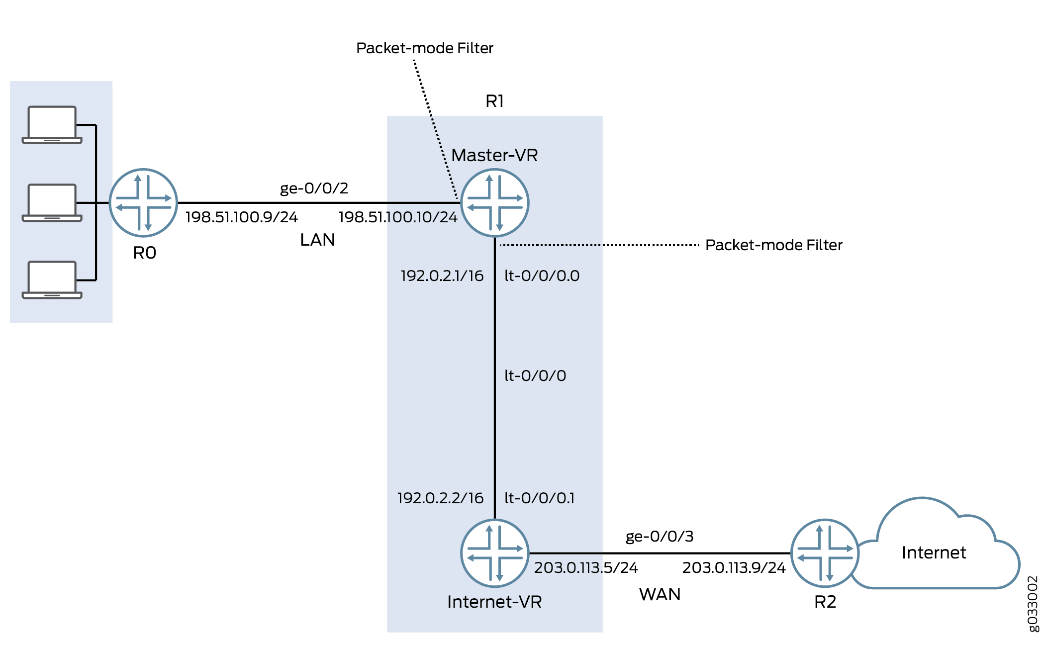
この例では、各デバイス上のインターフェイスのIPアドレスを設定します。デバイスR0の場合、198.51.100.9/24;R1の場合、は198.51.100.10/24および203.0.113.5/24です。R2の場合は203.0.113.9/24です。デバイスR1では、ルーティングインスタンス間に内部サービスインターフェイスlt-0/0/0を設定し、2つの仮想デバイス間のピア関係を設定します。次に、プライマリVRゾーンとインターネットVRゾーンの2つのセキュリティゾーンを作成し、関連するインターフェイスを割り当てて、サポートされているすべてのアプリケーションとプロトコルを許可するように設定します。
次に、ポリシーを設定し、すべてのパケットが許可されるように指定します。仮想デバイスルーティングインスタンスInternet-VRを設定し、フローベース転送用のインターフェイスを割り当てます。デバイスR0、R1、およびR2でOSPFを有効にします。デバイスR2では、パケットモードアクション修飾子を含む条件bypass-flow-termでフィルターbypass-flow-filterを設定します。一致条件を指定していないため、このフィルターは適用されているインターフェイスを通過するすべてのトラフィックに適用されます。
最後に、デバイスR1で、ファイアウォールフィルターbypass-flow-filterを内部インターフェイスge-0/0/2.0およびlt-0/0/0.0に適用します。Internet-VRルーティングインスタンスに関連付けられたインターフェイスには、フィルターを適用しません。その結果、プライマリルーティングインスタンスに関連付けられたLANインターフェイスを通過するすべてのトラフィックはパケットベース転送を使用し、Internet-VRルーティングインスタンスを通過するすべてのトラフィックはフローベース転送を使用します。
図4は、この例で使用されているネットワークトポロジーを示しています。
 のための選択的ステートレスパケットベースサービス
プライベートLANに面したインターフェイスにはセキュリティサービスは必要ありませんが、WANに面したインターフェイスにはセキュリティが必要です。この例では、パケットベースの転送を処理するルーティングインスタンスとフローベースの転送を処理する2つのルーティングインスタンスを設定することで、セキュアなトラフィックとあまり安全でないトラフィックに対して、パケットベースとフローベースの両方の転送を設定することにしました。
設定
手順
CLIクイックコンフィグレーション
この例をすばやく設定するには、以下のコマンドをコピーしてテキストファイルに貼り付け、改行を削除して、ネットワーク設定に一致させる必要がある詳細を変更し、コマンドを [edit] 階層レベルのCLIにコピーアンドペーストして、設定モードから commit を入力します。
{device R0}
set interfaces description “Connect to Primary VR” ge-0/0/2 unit 0 family inet address 198.51.100.9/24
set protocols ospf area 0.0.0.0 interface ge-0/0/2.0
{device R1}
set interfaces description “Connect to R0” ge-0/0/2 unit 0 family inet address 198.51.100.10/24
set interfaces description “Connect to R2” ge-0/0/3 unit 0 family inet address 203.0.113.5/24
set interfaces lt-0/0/0 unit 0 encapsulation frame-relay dlci 100 peer-unit 1 family inet address 192.0.2.1/16
set interfaces lt-0/0/0 unit 1 encapsulation frame-relay dlci 100 peer-unit 0 family inet address 192.0.2.2/16
set security zones security-zone Primary-VR-zone host-inbound-traffic system-services all
set security zones security-zone Primary-VR-zone host-inbound-traffic protocols all
set security zones security-zone Primary-VR-zone interfaces ge-0/0/2.0
set security zones security-zone Primary-VR-zone interfaces lt-0/0/0.0
set security zones security-zone Internet-VR-zone host-inbound-traffic system-services all
set security zones security-zone Internet-VR-zone host-inbound-traffic protocols all
set security zones security-zone Internet-VR-zone interfaces ge-0/0/3.0
set security zones security-zone Internet-VR-zone interfaces lt-0/0/0.1
set security policies default-policy permit-all
set routing-instances Internet-VR instance-type virtual-router interface lt-0/0/0.1
set routing-instances Internet-VR instance-type virtual-router interface ge-0/0/3.0
set protocols ospf area 0.0.0.0 interface ge-0/0/2.0
set protocols ospf area 0.0.0.0 interface lt-0/0/0.0
set routing-instances Internet-VR protocols ospf area 0.0.0.0 interface lt-0/0/0.1
set routing-instances Internet-VR protocols ospf area 0.0.0.0 interface ge-0/0/3.0
set firewall family inet filter bypass-flow-filter term bypass-flow-term then accept
set firewall family inet filter bypass-flow-filter term bypass-flow-term then packet-mode
set interfaces ge-0/0/2 unit 0 family inet filter input bypass-flow-filter
set interfaces lt-0/0/0 unit 0 family inet filter input bypass-flow-filter
{device R2}
set interfaces description “Connect to Internet-VR” ge-0/0/3 unit 0 family inet address 203.0.113.9/24
set protocols ospf area 0.0.0.0 interface ge-0/0/3
ステップバイステップの手順
次の例では、設定階層のさまざまなレベルに移動する必要があります。その方法の詳細については、『CLIユーザーガイド』の「構成モードでのCLIエディターの使用」を参照してください。
エンドツーエンドのパケットベース転送用に、選択的なステートレスパケットベースサービスを設定するには:
-
インターフェイスのIPアドレスを設定します。
{device R0} [edit] user@host#set interfaces description “Connect to Primary VR” ge-0/0/2 unit 0 family inet address 198.51.100.9/24{device R1} [edit] user@host#set interfaces description “Connect to R0” ge-0/0/2 unit 0 family inet address 198.51.100.10/24user@host#set interfaces description “Connect to R2” ge-0/0/3 unit 0 family inet address 203.0.113.5/24{device R2} [edit] user@host#set interfaces description “Connect to Internet-VR” ge-0/0/3 unit 0 family inet address 203.0.113.9/24 -
ルーティングインスタンス間の内部サービスインターフェイスを設定します。
{device R1} [edit] user@host#set interfaces lt-0/0/0 unit 0 encapsulation frame-relay dlci 100 peer-unit 1 family inet address 192.0.2.1/16user@host#set interfaces lt-0/0/0 unit 1 encapsulation frame-relay dlci 100 peer-unit 0 family inet address 192.0.2.2/16 -
セキュリティゾーンを設定します。
{device R1} [edit] user@host#set security zones security-zone Primary-VR-zone host-inbound-traffic system-services alluser@host#set security zones security-zone Primary-VR-zone host-inbound-traffic protocols alluser@host#set security zones security-zone Primary-VR-zone interfaces ge-0/0/2.0user@host#set security zones security-zone Primary-VR-zone interfaces lt-0/0/0.0user@host#set security zones security-zone Internet-VR-zone host-inbound-traffic system-services alluser@host#set security zones security-zone Internet-VR-zone host-inbound-traffic protocols alluser@host#set security zones security-zone Internet-VR-zone interfaces ge-0/0/3.0user@host#set security zones security-zone Internet-VR-zone interfaces lt-0/0/0.1 -
ポリシーを設定します。
{device R1} [edit] user@host#set security policies default-policy permit-all -
仮想デバイスのルーティングインスタンスを設定します。
{device R1} [edit] user@host#set routing-instances Internet-VR instance-type virtual-router interface lt-0/0/0.1user@host#set routing-instances Internet-VR instance-type virtual-router interface ge-0/0/3.0 -
ネットワーク内のすべてのインターフェイスで OSPF を有効にします。
{device R0} [edit] user@host#set protocols ospf area 0.0.0.0 interface ge-0/0/2.0{device R1 for Primary-VR} [edit] user@host#set protocols ospf area 0.0.0.0 interface ge-0/0/2.0user@host#set protocols ospf area 0.0.0.0 interface lt-0/0/0.0{device R1 for Internet-VR} [edit] user@host#set routing-instances Internet-VR protocols ospf area 0.0.0.0 interface lt-0/0/0.1user@host#set routing-instances Internet-VR protocols ospf area 0.0.0.0 interface ge-0/0/3.0{device R2} [edit] user@host#set protocols ospf area 0.0.0.0 interface ge-0/0/3 -
ファイアウォールフィルターを作成し、パケットベースの転送トラフィックの条件を定義します。
{device R1} [edit] user@host#set firewall family inet filter bypass-flow-filter term bypass-flow-term then acceptuser@host#set firewall family inet filter bypass-flow-filter term bypass-flow-term then packet-mode -
ファイアウォールフィルターを関連するインターフェイスに適用します。
{device R1} [edit] user@host#set interfaces ge-0/0/2 unit 0 family inet filter input bypass-flow-filteruser@host#set interfaces lt-0/0/0 unit 0 family inet filter input bypass-flow-filter
結果
設定モードから、 show interfaces、 show protocols、 show security、 show routing-instances、および show firewall コマンドを入力して設定を確認します。出力に意図した設定が表示されない場合は、この例の設定手順を繰り返して修正します。
{device R0}
[edit]
user@host# show interfaces
ge-0/0/2 {
description “Connect to Primary-VR”
unit 0 {
family inet {
address 198.51.100.9/24
}
}
}
{device R0}
[edit]
user@host# show protocols
ospf {
area 0.0.0.0/0 {
interface ge-0/0/2.0;
}
}
{device R2}
[edit]
user@host# show interfaces
ge-0/0/3 {
description “Connect to Internet-VR”
unit 0 {
family inet {
address 203.0.113.9/24;
}
}
}
{device R2}
[edit]
user@host# show protocols
ospf {
area 0.0.0.0/0 {
interface ge-0/0/3.0;
}
}
{device R1}
[edit]
user@host# show interfaces
ge-0/0/2 {
description “Connect to R0”
unit 0 {
family inet {
filter {
input bypass-flow-filter;
}
address 198.51.100.10/24;
}
}
}
lt-0/0/0 {
unit 0 {
encapsulation frame-relay;
dlci 100;
peer-unit 1;
family inet {
filter {
input bypass-flow-filter
}
address 192.0.2.1/16;
}
}
unit 1{
encapsulation frame-relay;
dlci 100;
peer-unit 0;
family inet {
address 192.0.2.2/16 ;
}
}
}
{device R1}
[edit]
user@host# show protocols
ospf {
area 0.0.0.0/0 {
interface ge-0/0/2.0;
interface lt-0/0/0.0;
}
}
{device R1}
[edit]
user@host# show firewall
filter bypass-flow-filter {
term bypass-flow-term {
then {
packet-mode;
accept;
}
}
}
{device R1}
[edit]
user@host# show routing-instances
Internet-VR {
instance-type virtual-router;
interface lt-0/0/0.1;
interface ge-0/0/3.0;
protocols {
ospf {
area 0.0.0.0 {
interface ge-0/0/3.0;
lt-0/0/0.1;
}
}
}
}
{device R1}
[edit]
user@host# show security
security zone Primary-VR-zone {
host-inbound-traffic {
system-services {
all;
{
protocols {
all;
{
{
intefaces {
ge-0/0/2.0;
lt-0/0/0.0;
{
{
security zone Internet-VR-zone {
host-inbound-traffic {
system-services {
all;
{
protocols {
all;
}
}
intefaces {
ge-0/0/3.0;
lt-0/0/0.1;
{
{
policies {
default-policy {
permit-all;
}
}
デバイスの設定が完了したら、設定モードから commit を入力します。
検証
設定が正常に機能していることを確認します。
パケットベースからフローベースの設定の検証
目的
選択的なステートレスパケットベースサービスが、パケットベースからフローベースの転送用に設定されていることを確認します。
アクション
設定モードから、 show interfaces、 show protocols、 show security、 show routing-instances、および show firewall コマンドを入力します。
出力が、ファイアウォールフィルター、ルーティングインスタンス、インターフェイス、ポリシーの意図した設定を示していることを確認します。
パケットをテストする順序で用語が表示されていることを確認します。 insert コマンドを使用して、ファイアウォールフィルター内で用語を移動できます。
LANトラフィックでのセッション確立の検証
目的
LAN内のインターフェイスでトラフィックが送信されたときに、セッションが確立されていることを確認します。
アクション
セッションが確立されていることを確認するには、以下のタスクを実行します。
-
デバイス
R1で、動作モードからclear security flow session allコマンドを入力して、既存のセキュリティフローセッションをすべてクリアします。 -
デバイス
R0で、動作モードからpingコマンドを入力して、デバイスPrimary-VRにトラフィックを送信します。 -
デバイス
R1で、デバイスからトラフィックがR1経由R0送信されている場合、動作モードからshow security flow sessionコマンドを入力します。
確立されたセッションを確認するには、pingコマンドがパケットを送受信しているときに必ずshow security flow sessionコマンドを入力してください。
{device R0}
user@host> ping 192.0.2.1
PING 192.0.2.1 (192.0.2.1): 56 data bytes 64 bytes from 192.0.2.1: icmp_seq=0 ttl=63 time=2.208 ms 64 bytes from 192.0.2.1: icmp_seq=1 ttl=63 time=2.568 ms 64 bytes from 192.0.2.1: icmp_seq=2 ttl=63 time=2.573 ms 64 bytes from 192.0.2.1: icmp_seq=3 ttl=63 time=2.310 ms 64 bytes from 192.0.2.1: icmp_seq=4 ttl=63 time=1.566 ms 64 bytes from 192.0.2.1: icmp_seq=5 ttl=63 time=1.569 ms ...
{device R1}
user@host> show security flow session
0 sessions displayed
出力は、R0からPrimary-VRに送信するトラフィックと、確立されたセッションなしを示しています。この例では、社内のLANトラフィックのインターフェイスge-0/0/0とlt-0/0/0.0にpacket-modeアクション修飾子を使用してbypass-flow-filterを適用しました。この出力では、2つのインターフェイス間のトラフィックがフローベース転送を正しくバイパスしているため、セッションが確立されていないことを確認します。
インターネットトラフィックでのセッション確立の検証
目的
トラフィックがインターネットに送信されたときにセッションが確立されていることを確認します。
アクション
インターネットへのトラフィックがフローベースの転送を使用しており、セッションが確立されていることを確認するには、以下のタスクを実行します。
-
デバイス
R1で、動作モードからclear security flow session allコマンドを入力して、既存のセキュリティフローセッションをすべてクリアします。 -
デバイス
R0で、動作モードからpingコマンドを入力して、デバイスR2にトラフィックを送信します。 -
デバイス
R1で、トラフィックがR1を介してR0からR2に送信されている場合、動作モードからshow security flow sessionコマンドを入力します。root@host> show security flow session Flow Sessions on FPC10 PIC1: Total sessions: 0 Flow Sessions on FPC10 PIC2: Total sessions: 0 Flow Sessions on FPC10 PIC3: Total sessions: 0
確立されたセッションを確認するには、pingコマンドがパケットを送受信しているときに必ずshow security flow sessionコマンドを入力してください。
{device R0}
user@host> ping 192.0.2.1 -c 10
PING 60.0.0.1 (60.0.0.1) 56(84) bytes of data. 64 bytes from 192.0.2.1: icmp_seq=1 ttl=64 time=1.98 ms 64 bytes from 192.0.2.1: icmp_seq=2 ttl=64 time=1.94 ms 64 bytes from 192.0.2.1: icmp_seq=3 ttl=64 time=1.92 ms 64 bytes from 192.0.2.1: icmp_seq=4 ttl=64 time=1.89 ms ...
{device R1}
user@host> show security flow session
Session ID: 189900, Policy name: default-policy/2, Timeout: 2
  In: 198.51.100.9/0 --> 192.0.2.1/5924;icmp, If: lt-0/0/0.1
  Out: 192.0.2.1/5924 --> 198.51.100.9/0;icmp, If: ge-0/0/3.0

Session ID: 189901, Policy name: default-policy/2, Timeout: 2
  In: 198.51.100.9/1 --> 192.0.2.1/5924;icmp, If: lt-0/0/0.1
  Out: 192.0.2.1/5924 --> 198.51.100.9/1;icmp, If: ge-0/0/3.0

Session ID: 189902, Policy name: default-policy/2, Timeout: 4
  In: 198.51.100.9/2 --> 192.0.2.1/5924;icmp, If: lt-0/0/0.1
  Out: 192.0.2.1/5924 --> 198.51.100.9/2;icmp, If: ge-0/0/3.0

 3 sessions displayed
出力は、デバイスからR2および確立されたセッションに送信されるトラフィックR0を示しています。この例では、社内のインターネットトラフィックのルーティングインスタンスInternet-VRでpacket-modeアクション修飾子を使用したbypass-flow-filterを適用しませんでした。この出力では、インターネットへのトラフィックがフローベース転送を正しく使用しているため、セッションが確立されていることを検証します。
セッションは、 lt-0/0/0.1 と ge-0/0/3 の間でトラフィックが流れている場合にのみ確立され、 ge-0/0/2 と lt-0/0/0.0の間でトラフィックが流れているときは確立されないことに注意してください。
変更履歴テーブル
サポートされる機能は、使用しているプラットフォームとリリースによって決まります。 機能エクスプローラー を使用して、機能がお使いのプラットフォームでサポートされているかどうかを確認します。