例:EVPN を使用した VXLAN データセンターの相互接続の設定
この例では、EVPN(イーサネットVPN)を使用してVXLAN(仮想拡張ローカルエリアネットワーク)データセンター接続を設定し、データセンターの相互接続(DCI)ソリューションとしてのEVPNのメリットを活用する方法を示します。
必要条件
この例では、以下のハードウェアとソフトウェアのコンポーネントを使用しています。
VXLANトンネルエンドポイント(VTEP)として機能する、異なるDC(データセンター)にある2台のプロバイダエッジ(PE)デバイス。
2 台のカスタマー エッジ(CE)デバイス。
各PEおよびCEデバイスに接続された4台のホストデバイス。
開始する前に、以下を実行します。
デバイスインターフェイスを設定します。
すべてのデバイスでOSPFなどのIGPを設定します。
PE デバイス間で BGP セッションを確立します。
PE デバイスで MPLS と RSVP を設定します。
CE デバイスと PE デバイスのルーティング インスタンスで PIM を設定します。
概要
VXLANは、トンネリングスキームを使用してデータセンター内接続を提供し、レイヤー2接続を介在するレイヤー3ネットワーク上に拡張するテクノロジーです。
一方、EVPN(イーサネットVPN)テクノロジーは、MPLS/IPネットワーク上でBGPコントロールプレーンを使用して、高度なマルチホーミング機能を備えたマルチポイントレイヤー2 VPNサービスのソリューションを提供します。
データ センターの接続にはいくつかのソリューションがありますが、EVPN と VXLAN の統合には、既存の MPLS データ センター相互接続(DCI)技術よりも優れたメリットがあります。
EVPN は、参加するデータセンター境界ルーター(DCBR)間でレイヤー 2 MAC アドレスとレイヤー 3 IP アドレスの情報を交換する拡張コントロール プレーン手順を追加することで、次世代 DCI 向けのメカニズムを提供します。EVPNは、アクティブ/アクティブ冗長性、エイリアシング、mass MAC withdrawalなどの高度な機能を備えており、シームレスなVMモビリティや最適なIPルーティングなどのDCIの課題に対処するのに役立つため、EVPNを介したVXLANソリューションの提供が不可欠になっています。
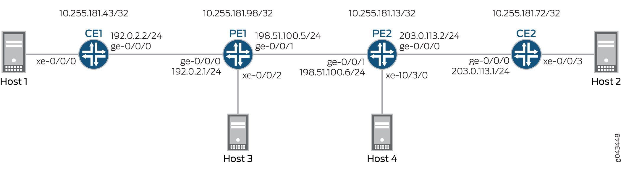
図 1 は、異なるデータ センター(それぞれ DC1 および DC2)にあるデバイス PE1 と PE2 間で、EVPN を使用した VXLAN データセンターの相互接続を示しています。各 PE デバイスは、1 つの CE デバイスと 1 つのホストに接続されています。すべての PE および CE デバイスは VLAN 10 の下に設定され、同じ VXLAN ネットワーク識別子(VNI)10 が設定されます。デバイスCE1とPE1は192.168.1.10のマルチキャストグループに属し、デバイスCE2とPE2は172.16.1.10のマルチキャストグループに属します。
位相幾何学
 を使用した VXLAN データセンターの相互接続
構成
CLIクイック構成
この例を素早く設定するには、以下のコマンドをコピーしてテキスト・ファイルに貼り付け、改行を削除し、ネットワーク・コンフィギュレーションに合わせて必要な詳細を変更し、[edit]階層レベルのCLIにコマンドをコピー&ペーストし、コンフィギュレーション・モードからcommitを入力してください。
CE1の
set interfaces xe-0/0/0 vlan-tagging
set interfaces xe-0/0/0 encapsulation flexible-ethernet-services
set interfaces xe-0/0/0 unit 10 encapsulation vlan-bridge
set interfaces xe-0/0/0 unit 10 vlan-id 10
set interfaces ge-0/0/0 unit 0 family inet address 192.0.2.2/24
set interfaces ge-0/0/0 unit 0 family mpls
set interfaces lo0 unit 0 family inet address 10.255.181.43/32
set protocols ospf area 0.0.0.0 interface ge-0/0/0.0
set protocols ospf area 0.0.0.0 interface lo0.0 passive
set protocols ospf area 0.0.0.0 interface fxp0.0 disable
set protocols pim rp local address 10.255.181.43
set protocols pim interface all
set bridge-domains evpn10 vlan-id 10
set bridge-domains evpn10 interface xe-0/0/0.10
set bridge-domains vxlan vni 10
set bridge-domains vxlan multicast-group 172.16.1.10
set bridge-domains vxlan encapsulate-inner-vlan
set bridge-domains vxlan decapsulate-accept-inner-vlan
CE2の
set interfaces xe-0/0/3 vlan-tagging
set interfaces xe-0/0/3 encapsulation flexible-ethernet-services
set interfaces xe-0/0/3 unit 10 encapsulation vlan-bridge
set interfaces xe-0/0/3 unit 10 vlan-id 10
set interfaces lo0 unit 0 family inet address 10.255.181.72/32
set protocols ospf area 0 interface ge-0/0/0.0
set protocols ospf area 0 interface lo0.0 passive
set protocols ospf area 0 interface fxp0.0 disable
set protocols pim rp local address 10.255.181.72
set protocols pim interface all
set bridge-domains evpn10 vlan-id 10
set bridge-domains evpn10 interface xe-0/0/3.10
set bridge-domains vxlan vni 10
set bridge-domains vxlan multicast-group 192.168.1.10
set bridge-domains vxlan encapsulate-inner-vlan
set bridge-domains vxlan decapsulate-accept-inner-vlan
PE1
set interfaces xe-0/0/2 vlan-tagging
set interfaces xe-0/0/2 encapsulation flexible-ethernet-services
set interfaces xe-0/0/2 unit 10 encapsulation vlan-bridge
set interfaces xe-0/0/2 unit 10 vlan-id 10
set interfaces ge-0/0/0 unit 0 family inet address 192.0.2.1/24
set interfaces ge-0/0/1 mtu 1600
set interfaces ge-0/0/1 unit 0 family inet address 198.51.100.5/24
set interfaces ge-0/0/1 unit 0 family mpls
set interfaces lo0 unit 1 family inet address 10.255.181.98/32
set protocols rsvp interface all
set protocols mpls no-cspf
set protocols mpls label-switched-path to-PE2 to 10.255.181.13
set protocols mpls interface all
set protocols bgp family evpn signaling
set protocols bgp group ibgp type internal
set protocols bgp group ibgp neighbor 10.255.181.13 local-address 10.255.181.98
set protocols ospf area 0 interface ge-0/0/1.0
set protocols ospf area 0 interface fxp0.0 disable
set protocols ospf area 0 interface lo0.0 passive
set routing-instances evpn10 vtep-source-interface lo0.0
set routing-instances evpn10 instance-type evpn
set routing-instances evpn10 vlan-id 10
set routing-instances evpn10 interface xe-0/0/2.10
set routing-instances evpn10 vxlan vni 10
set routing-instances evpn10 vxlan multicast-group 172.16.1.10
set routing-instances evpn10 vxlan encapsulate-inner-vlan
set routing-instances evpn10 vxlan decapsulate-accept-inner-vlan
set routing-instances evpn10 route-distinguisher 10.255.181.98:10
set routing-instances evpn10 vrf-target target:10:10
set routing-instances evpn10 protocols evpn
set routing-instances evpna instance-type vrf
set routing-instances evpna route-distinguisher 10.255.181.98:11
set routing-instances evpna vrf-target target:65000:11
set routing-instances evpna vrf-table-label
set routing-instances vrf instance-type vrf
set routing-instances vrf interface ge-0/0/0.0
set routing-instances vrf interface lo0.0
set routing-instances vrf route-distinguisher 10.255.181.98:100
set routing-instances vrf vrf-target target:100:100
set routing-instances vrf protocols ospf area 0 interface lo0.0 passive
set routing-instances vrf protocols ospf area 0 interface ge-0/0/0.0
set routing-instances vrf protocols pim rp static address 10.255.181.43
set routing-instances vrf protocols pim interface all
PE2の
set interfaces ge-0/0/1 mtu 1600
set interfaces ge-0/0/1 unit 0 family inet address 198.51.100.6/24
set interfaces ge-0/0/1 unit 0 family mpls
set interfaces xe-10/3/0 vlan-tagging
set interfaces xe-10/3/0 encapsulation flexible-ethernet-services
set interfaces xe-10/3/0 unit 10 encapsulation vlan-bridge
set interfaces xe-10/3/0 unit 10 vlan-id 10
set interfaces lo0 unit 1 family inet address 10.255.181.13/32
set protocols rsvp interface all
set protocols mpls no-cspf
set protocols mpls label-switched-path to-PE1 to 10.255.181.98
set protocols mpls interface all
set protocols bgp family evpn signaling
set protocols bgp group ibgp type internal
set protocols bgp group ibgp neighbor 10.255.181.98 local-address 10.255.181.13
set protocols ospf area 0 interface ge-0/0/1.0
set protocols ospf area 0 interface fxp0.0 disable
set protocols ospf area 0 interface lo0.0 passive
set routing-instances evpn10 vtep-source-interface lo0.0
set routing-instances evpn10 instance-type evpn
set routing-instances evpn10 vlan-id 10
set routing-instances evpn10 interface xe-10/3/0.10
set routing-instances evpn10 vxlan vni 10
set routing-instances evpn10 vxlan multicast-group 192.168.1.10
set routing-instances evpn10 vxlan encapsulate-inner-vlan
set routing-instances evpn10 vxlan decapsulate-accept-inner-vlan
set routing-instances evpn10 route-distinguisher 10.255.181.13:10
set routing-instances evpn10 vrf-target target:10:10
set routing-instances evpn10 protocols evpn
set routing-instances evpna instance-type vrf
set routing-instances evpna route-distinguisher 10.255.181.13:11
set routing-instances evpna vrf-target target:65000:11
set routing-instances evpna vrf-table-label
set routing-instances vrf instance-type vrf
set routing-instances vrf interface xe-10/3/0.0
set routing-instances vrf interface lo0.0
set routing-instances vrf route-distinguisher 10.255.181.13:100
set routing-instances vrf vrf-target target:100:100
set routing-instances vrf protocols ospf area 0 interface lo0.0 passive
set routing-instances vrf protocols ospf area 0 interface xe-10/3/0.0
set routing-instances vrf protocols pim rp static address 10.255.181.72
set routing-instances vrf protocols pim interface all
プロシージャ
手順
次の例では、設定階層のいくつかのレベルに移動する必要があります。CLIのナビゲーションについては、「 1 コンフィグレーション・モードでのCLIエディタの使用」を参照してください。
デバイスCE1を設定するには:
適切なインターフェイス名、アドレス、およびその他のパラメーターを変更した後、デバイスCE2を対象にしたこの手順を繰り返します。
デバイスCE1インターフェイスを設定します。
[edit interfaces]
user@CE1# set xe-0/0/0 vlan-tagging
user@CE1# set xe-0/0/0 encapsulation flexible-ethernet-services
user@CE1# set xe-0/0/0 unit 10 encapsulation vlan-bridge
user@CE1# set xe-0/0/0 unit 10 vlan-id 10
user@CE1# set ge-0/0/0 unit 0 family inet address 192.0.2.2/24
user@CE1# set ge-0/0/0 unit 0 family mpls
user@CE1# set lo0 unit 0 family inet address 10.255.181.43/32
管理インターフェイスを除くデバイスCE1インターフェイスでOSPFを有効にします。
[edit protocols]
user@CE1# set ospf area 0.0.0.0 interface ge-0/0/0.0
user@CE1# set ospf area 0.0.0.0 interface lo0.0 passive
user@CE1# set ospf area 0.0.0.0 interface fxp0.0 disable
デバイスCE1のすべてのインターフェイスでPIMを有効にします。
[edit protocols]
user@CE1# set pim rp local address 10.255.181.43
user@CE1# set pim interface all
EVPNブリッジドメインを設定し、VLAN IDとインターフェイスを割り当てます。
[edit bridge-domains]
user@CE1# set evpn10 vlan-id 10
user@CE1# set evpn10 interface xe-0/0/0.10
VXLAN ブリッジ ドメインの設定、VXLAN ID、マルチキャスト グループ アドレス、カプセル化およびカプセル化解除パラメータの割り当てを行います。
[edit bridge-domains]
user@CE1# set vxlan vni 10
user@CE1# set vxlan multicast-group 172.16.1.10
user@CE1# set vxlan encapsulate-inner-vlan
user@CE1# set vxlan decapsulate-accept-inner-vlan
手順
デバイスPE1を設定するには:
適切なインターフェイス名、アドレス、およびその他のパラメーターを変更した後、デバイスPE2のこの手順を繰り返します。
デバイスPE1インターフェイスを設定します。
[edit interfaces]
user@PE1# set xe-0/0/2 vlan-tagging
user@PE1# set xe-0/0/2 encapsulation flexible-ethernet-services
user@PE1# set xe-0/0/2 unit 10 encapsulation vlan-bridge
user@PE1# set xe-0/0/2 unit 10 vlan-id 10
user@PE1# set ge-0/0/0 unit 0 family inet address 192.0.2.1/24
user@PE1# set ge-0/0/1 mtu 1600
user@PE1# set ge-0/0/1 unit 0 family inet address 198.51.100.5/24
user@PE1# set ge-0/0/1 unit 0 family mpls
user@PE1# set lo0 unit 1 family inet address 10.255.181.98/32
デバイス PE1 のすべてのインターフェイスで MPLS と RSVP を有効にします。
[edit protocols]
user@PE1# set rsvp interface all
user@PE1# set mpls no-cspf
user@PE1# set mpls interface all
デバイスPE1からデバイスPE2へのlabel-switched-pathを設定します。
[edit protocols]
user@PE1# set mpls label-switched-path to-PE2 to 10.255.181.13
デバイス PE1 と PE2 間の内部 BGP ピアリングを設定し、BGP セッションの EVPN シグナリングを有効にします。
[edit protocols]
user@PE1# set bgp family evpn signaling
user@PE1# set bgp group ibgp type internal
user@PE1# set bgp group ibgp neighbor 10.255.181.13 local-address 10.255.181.98
管理インターフェイスを除くデバイス PE1 インターフェイスで OSPF を設定します。
[edit protocols]
user@PE1# set ospf area 0 interface ge-0/0/1.0
user@PE1# set ospf area 0 interface fxp0.0 disable
user@PE1# set ospf area 0 interface lo0.0 passive
EVPNルーティング インスタンスを設定し、VXLANトンネルエンドポイントソースインターフェイス、VLAN IDを割り当て、ルート区別とVRFターゲット値を割り当て、デバイスPE1インターフェイスをルーティング インスタンスに割り当てます。
[edit routing-instances]
user@PE1# set evpn10 vtep-source-interface lo0.0
user@PE1# set evpn10 instance-type evpn
user@PE1# set evpn10 vlan-id 10
user@PE1# set evpn10 interface xe-0/0/2.10
user@PE1# set evpn10 route-distinguisher 10.255.181.13:10
user@PE1# set evpn10 vrf-target target:10:10
user@PE1# set evpn10 protocols evpn
EVPN ルーティング インスタンスの VXLAN ID、マルチキャスト グループ アドレス、カプセル化およびカプセル化解除パラメータを割り当てます。
[edit routing-instances]
user@PE1# set evpn10 vxlan vni 10
user@PE1# set evpn10 vxlan multicast-group 172.16.1.10
user@PE1# set evpn10 vxlan encapsulate-inner-vlan
user@PE1# set evpn10 vxlan decapsulate-accept-inner-vlan
最初の VPN ルーティングおよび転送(VRF)ルーティング インスタンスを設定し、ルート識別と vrf-target 値を割り当てます。
[edit routing-instances]
user@PE1# set evpna instance-type vrf
user@PE1# set evpna route-distinguisher 10.255.181.13:11
user@PE1# set evpna vrf-target target:65000:11
user@PE1# set evpna vrf-table-label
2 番目の VRF ルーティング インスタンスを設定し、デバイス PE1 インターフェイス、ルート識別子、および vrf-target 値を割り当てます。
[edit routing-instances]
user@PE1# set vrf instance-type vrf
user@PE1# set vrf interface ge-0/0/0.0
user@PE1# set vrf interface lo0.0
user@PE1# set vrf route-distinguisher 10.255.181.13:100
user@PE1# set vrf vrf-target target:100:100
2 つ目の VRF ルーティング インスタンスの OSPF および PIM プロトコルを設定します。
[edit routing-instances]
user@PE1# set vrf protocols ospf area 0 interface lo0.0 passive
user@PE1# set vrf protocols ospf area 0 interface ge-0/0/0.0
user@PE1# set vrf protocols pim rp static address 10.255.181.43
user@PE1# set vrf protocols pim interface all
業績
設定モードから、 show interfaces、 show protocols、および show routing-instances コマンドを入力して設定を確認します。出力結果に意図した設定内容が表示されない場合は、この例の手順を繰り返して設定を修正します。
CE1の
user@CE1# show interfaces
xe-0/0/0 {
    vlan-tagging;
    encapsulation flexible-ethernet-services;
    unit 10 {
        encapsulation vlan-bridge;
        vlan-id 10;
    }
}
ge-0/0/0 {
    unit 0 {
        family inet {
            address 192.0.2.2/24;
        }
        family mpls;
    }
}
lo0 {
    unit 0 {
        family inet {
            address 10.255.181.43/32;
        }
    }
}
user@CE1# show protocols
ospf {
    area 0.0.0.0 {
        interface ge-0/0/0.0;
        interface lo0.0 {
            passive;
        }
        interface fxp0.0 {
            disable;
        }
    }
}
pim {
    rp {
        local {
            address 10.255.181.43;
        }
    }
    interface all;
}
user@CE1# show bridge-domains
evpn10 {
    vlan-id 10;
    interface xe-0/0/0.10;
    vxlan {
        vni 10;
        multicast-group 172.16.1.10;
        encapsulate-inner-vlan;
        decapsulate-accept-inner-vlan;
    }
}
PE1
user@PE1# show interfaces
xe-0/0/2 {
    vlan-tagging;
    encapsulation flexible-ethernet-services;
    unit 10 {
        encapsulation vlan-bridge;
        vlan-id 10;
    }
}
ge-0/0/0 {
    unit 0 {
        family inet {
            address 192.0.2.1/24;
        }
    }
}
ge-0/0/1 {
    mtu 1600;
    unit 0 {
        family inet {
            address 198.51.100.5/24;
        }
        family mpls;
    }
}
lo0 {
    unit 1 {
        family inet {
            address 10.255.181.98/32;
        }
    }
}
user@PE1# show protocols
rsvp {
    interface all;
}
mpls {
    no-cspf;
    label-switched-path to-PE2 {
        to 10.255.181.13;
    }
    interface all;
}
bgp {
    family evpn {
        signaling;
    }
    group ibgp {
        type internal;
        neighbor 10.255.181.13 {
            local-address 10.255.181.98;
        }
    }
}
ospf {
    area 0.0.0.0 {
        interface ge-0/0/1.0;
        interface fxp0.0 {
            disable;
        }
        interface lo0.0 {
            passive;
        }
    }
}
user@PE1# show routing-instances
evpn10 {
    vtep-source-interface lo0.0;
    instance-type evpn;
    vlan-id 10;
    interface xe-0/0/2.10;
    vxlan {
        vni 10;
        multicast-group 172.16.1.10;
        encapsulate-inner-vlan;
        decapsulate-accept-inner-vlan;
    }
    route-distinguisher 10.255.181.13:10;
    vrf-target target:10:10;
    protocols {
        evpn;
    }
}
evpna {
    instance-type vrf;
    route-distinguisher 10.255.181.98:11;
    vrf-target target:65000:11;
    vrf-table-label;
}
vrf {
    instance-type vrf;
    interface ge-0/0/0.0;
    interface lo0.0;
    route-distinguisher 10.255.181.98:100;
    vrf-target target:100:100;
    protocols {
        ospf {
            area 0.0.0.0 {
                interface lo0.0 {
                    passive;
                }
                interface ge-0/0/0.0;
            }
        }
        pim {
            rp {
                static {
                    address 10.255.181.43;
                }
            }
            interface all;
        }
    }
}
検証
設定が正常に機能していることを確認します。
MAC ラーニングの検証
目的
CEおよびPEデバイスのブリッジングとEVPN MACテーブルエントリーを検証します。
アクション
デバイスCE1で、ブリッジングMACテーブルのエントリーを決定します。
運用モードから、 show bridge mac-table コマンドを実行します。
user@CE1> show bridge mac-table

 MAC flags       (S -static MAC, D -dynamic MAC, L -locally learned, C -Control MAC
     O -OVSDB MAC, SE -Statistics enabled, NM -Non configured MAC, R -Remote PE MAC)

 Routing instance : default-switch
  Bridging domain : evpn10, VLAN : 10
    MAC                 MAC      Logical          NH     RTR
    address             flags    interface        Index  ID
    00:00:00:00:00:11   D        xe-0/0/0.10
    00:00:00:00:00:22   D        vtep.32769
デバイスPE1で、EVPN MACテーブルのエントリーを確認します。
動作モードから、 show evpn mac-table コマンドを実行します。
user@PE1> show evpn mac-table

 MAC flags       (S -static MAC, D -dynamic MAC, L -locally learned, C -Control MAC
     O -OVSDB MAC, SE -Statistics enabled, NM -Non configured MAC, R -Remote PE MAC)

 Routing instance : evpn10
  Bridging domain : __evpn10__, VLAN : 10
    MAC                 MAC      Logical          NH     RTR
    address             flags    interface        Index  ID
    00:00:00:00:00:11   D        vtep.32769
    00:00:00:00:00:22   DC                        1048576 1048576
意味
ブリッジングテーブルとEVPN MACテーブルは、VLAN設定を学習しています。
PIM の到達可能性の確認
目的
CE および PE デバイスで PIM 設定が正しく機能していることを確認します。
アクション
デバイスCE1で、PIM設定を確認します。
運用モードから、 show pim rps extensive コマンドを実行します。
user@CE1> show pim rps extensive
 Instance: PIM.master

 address-family INET

 RP: 10.255.181.43
 Learned via: static configuration
 Mode: Sparse
 Time Active: 00:06:08
 Holdtime: 150
 Device Index: 161
 Subunit: 32769
 Interface: pd-0/2/0.32769
 Static RP Override: Off
 Group Ranges:
         224.0.0.0/4
 Register State for RP:
 Group           Source          FirstHop        RP Address      State    Timeout
 172.16.1.10      203.1.113.11       203.1.113.11       10.255.181.43   Receive      171

 address-family INET6
運用モードから、 show pim join extensive コマンドを実行します。
user@CE1> show pim join extensive
 Instance: PIM.master Family: INET
 R = Rendezvous Point Tree, S = Sparse, W = Wildcard

 Group: 172.16.1.10
     Source: *
     RP: 10.255.181.43
     Flags: sparse,rptree,wildcard
     Upstream interface: Local
     Upstream neighbor: Local
     Upstream state: Local RP
     Uptime: 00:06:08
     Downstream neighbors:
         Interface: ge-0/0/0.0 (assert winner)
             192.0.2.1 State: Join Flags: SRW Timeout: 201
             Uptime: 00:05:08 Time since last Join: 00:00:08
             Assert Winner: 192.0.2.2 Metric: 0 Pref: 2147483648 Timeout: 82
         Interface: Pseudo-VXLAN
     Number of downstream interfaces: 2

 Group: 172.16.1.10
     Source: 10.255.181.43
     Flags: sparse,spt
     Upstream interface: Local
     Upstream neighbor: Local
     Upstream state: Local Source, Local RP, No Prune to RP
     Keepalive timeout: 338
     Uptime: 00:04:15
     Downstream neighbors:
         Interface: ge-0/0/0.0
             192.0.2.1 State: Join Flags: S Timeout: 201
             Uptime: 00:04:15 Time since last Join: 00:00:08
         Interface: Pseudo-VXLAN
     Number of downstream interfaces: 2

 Group: 172.16.1.10
     Source: 203.1.113.11
     Flags: sparse,spt
     Upstream interface: ge-0/0/0.0
     Upstream neighbor: 192.0.2.1 (assert winner)
     Upstream state: Local RP, Join to Source, No Prune to RP
     Keepalive timeout: 338
     Uptime: 00:04:15
     Downstream neighbors:
         Interface: ge-0/0/0.0 (pruned)
             192.0.2.1 State: Prune Flags: SR Timeout: 201
             Uptime: 00:04:15 Time since last Prune: 00:00:08
             Assert Winner: 192.0.2.1 Metric: 0 Pref: 0 Timeout: 179
         Interface: Pseudo-VXLAN
     Number of downstream interfaces: 2

 Instance: PIM.master Family: INET6
 R = Rendezvous Point Tree, S = Sparse, W = Wildcard
意味
PIM を使用したデバイスの到達可能性は、設定どおりに動作しています。
VXLAN の到達可能性の検証
目的
異なるデータ センター内の VTEP 間の接続を確認します。
アクション
動作モードから、 show l2-learning vxlan-tunnel-end-point source、 show l2-learning vxlan-tunnel-end-point remote、および show interfaces vtep コマンドを実行します。
user@PE1> show l2-learning vxlan-tunnel-end-point source
 Logical System Name       Id  SVTEP-IP         IFL   L3-Idx
        <default>                 0   203.1.113.11        lo0.0    7
     L2-RTT                   Bridge Domain              VNID     MC-Group-IP

     evpn10                   __evpn10__                 10       172.16.1.10
user@PE2> show l2-learning vxlan-tunnel-end-point source
 Logical System Name       Id  SVTEP-IP         IFL   L3-Idx
        <default>                 0   203.1.113.12        lo0.0    7
     L2-RTT                   Bridge Domain              VNID     MC-Group-IP
     evpn10                   __evpn10__                 10       192.168.1.10
user@PE1> show l2-learning vxlan-tunnel-end-point remote
 Logical System Name       Id  SVTEP-IP         IFL   L3-Idx
        <default>                 0   203.1.113.11        lo0.0    7
  RVTEP-IP         IFL-Idx   NH-Id
  10.255.181.43    2684275660 2684275660
     VNID          MC-Group-IP
     10            172.16.1.10
user@PE2> show l2-learning vxlan-tunnel-end-point remote
 Logical System Name       Id  SVTEP-IP         IFL   L3-Idx
        <default>                 0   203.1.113.12        lo0.0    7
  RVTEP-IP         IFL-Idx   NH-Id
  10.255.181.98    351       661
     VNID          MC-Group-IP
     10            192.168.1.10
user@PE1> show interfaces vtep
 Physical interface: vtep, Enabled, Physical link is Up
   Interface index: 133, SNMP ifIndex: 508
   Type: Software-Pseudo, Link-level type: VxLAN-Tunnel-Endpoint, MTU: 1600, Speed: Unlimited
   Device flags   : Present Running
   Interface flags: SNMP-Traps
   Link type      : Full-Duplex
   Link flags     : None
   Last flapped   : Never
     Input packets : 0
     Output packets: 0

   Logical interface vtep.32768 (Index 339) (SNMP ifIndex 560)
     Flags: Up SNMP-Traps Encapsulation: ENET2
     Ethernet segment value: 00:00:00:00:00:00:00:00:00:00, Mode: Single-homed, Multi-homed status: Forwarding
     VXLAN Endpoint Type: Source, VXLAN Endpoint Address: 203.1.113.11, L2 Routing Instance: evpn10, L3 Routing Instance: vrf
     Input packets : 0
     Output packets: 0

   Logical interface vtep.32769 (Index 341) (SNMP ifIndex 567)
     Flags: Up SNMP-Traps Encapsulation: ENET2
     VXLAN Endpoint Type: Remote, VXLAN Endpoint Address: 10.255.181.43, L2 Routing Instance: evpn10, L3 Routing Instance: vrf
     Input packets : 143746
     Output packets: 95828
     Protocol bridge, MTU: 1600
       Flags: Trunk-Mode
意味
出力には、VXLAN の正しいトンネル送信元 IP アドレス(ループバック インターフェイスに割り当てられる)、VLAN、マルチキャスト グループが表示されます。デバイスPE1は、そのIPアドレス(ループバックインターフェイスに割り当てられたアドレス)が出力に表示されるため、到達可能です。また、出力は、VXLAN(VNI 10)および対応するマルチキャスト グループがリモート VTEP、デバイス PE2 で正しく設定されていることも示しています。