例:EVPN シグナリング メカニズムを使用した VPWS の設定
この例では、イーサネット仮想プライベートネットワーク(EVPN)シグナリングで仮想プライベートワイヤサービス(VPWS)を実装する方法を示しています。EVPNシグナリングを使用することで、BGPシグナリングVPNにシングルアクティブまたはオールアクティブのマルチホーミング機能を提供します。
必要条件
この例では、以下のハードウェアとソフトウェアのコンポーネントを使用しています。
Junos OS リリース 17.1 以降を実行、プロバイダ エッジ(PE)デバイスとして機能する 4 台の MXシリーズ ルーター
2台のカスタマーエッジ(CE)デバイス(この例ではMXシリーズルーターを使用)
概要とトポロジー
VPWS は、MPLS 上でレイヤ 2 VPN サービスを使用して、エンドカスタマーサイトを接続するポイントツーポイント接続のトポロジーを構築します。EVPNでは、レイヤー2仮想ブリッジを使用して分散した顧客サイトを接続できます。Junos OS リリース 17.1 以降では、これら 2 つの要素を組み合わせることで、EVPN シグナルの VPWS を提供できます。
vpws-service-idステートメントは、ネットワーク内のPEルーターに設定されたlocalおよびremoteサービス識別子に基づいて、EVPN-VPWSのエンドポイントを識別します。これらのエンドポイントは、BGP ベースの EVPN シグナリングを使用して自動検出され、サービス識別子ラベルが交換されます。
位相幾何学
この例では、4 台の PE ルーターと 2 台の CE ルーターで構成される 図 1 に示すトポロジーを使用します。ルーターCE1は、ルーターPE1およびPE2にマルチホームされています。ルーターCE2は、ルーターPE3およびPE4にマルチセムされています。
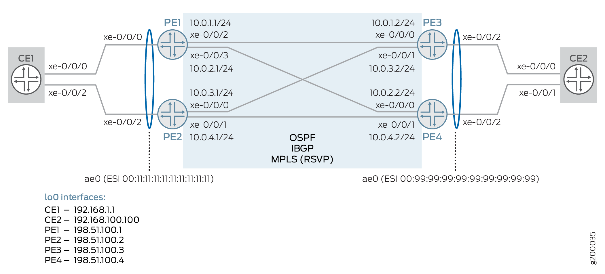
このシナリオでは、次の構成要素が使用されます。
CEデバイス:
関連するPEデバイスへの集合型イーサネット(AE)インターフェイス
PE デバイス:
AEインターフェイス、EVPNセグメント識別子(ESI)、関連するCEデバイスに向けて
コアでのOSPFとIBGP
コアでRSVPを使用したMPLS LSP
パケット単位のロードバランシング
インスタンスタイプ
evpn-vpwsを使用したルーティングインスタンスと、ローカルとリモートのエンドポイントを定義するvpws-service-idステートメント。
構成
CLIクイック構成
この例を迅速に設定するには、以下のコマンドをコピーして、テキスト ファイルに貼り付け、改行を削除し、ネットワーク設定に一致させる必要がある詳細情報を変更し、コマンドを [edit] 階層レベルで CLI にコピー アンド ペーストします。
CE1の
set interfaces xe-0/0/0 gigether-options 802.3ad ae0
set interfaces xe-0/0/2 gigether-options 802.3ad ae0
set chassis aggregated-devices ethernet device-count 1
set interfaces ae0 description "to PE1/2"
set interfaces ae0 flexible-vlan-tagging
set interfaces ae0 encapsulation flexible-ethernet-services
set interfaces ae0 aggregated-ether-options lacp active
set interfaces ae0 unit 100 encapsulation vlan-bridge
set interfaces ae0 unit 100 vlan-id 1000
set interfaces lo0 unit 0 family inet address 192.168.1.1/32
set policy-options policy-statement LB then load-balance per-packet
set routing-options forwarding-table export LB
set bridge-domains bd100 domain-type bridge
set bridge-domains bd100 vlan-id 1000
set bridge-domains bd100 interface ae0.100
CE2の
set interfaces xe-0/0/0 gigether-options 802.3ad ae0
set interfaces xe-0/0/1 gigether-options 802.3ad ae0
set chassis aggregated-devices ethernet device-count 1
set interfaces ae0 description "to PE3/4"
set interfaces ae0 flexible-vlan-tagging
set interfaces ae0 encapsulation flexible-ethernet-services
set interfaces ae0 aggregated-ether-options lacp active
set interfaces ae0 unit 100 encapsulation vlan-bridge
set interfaces ae0 unit 100 vlan-id 1000
set interfaces lo0 unit 0 family inet address 192.168.100.100/32
set policy-options policy-statement LB then load-balance per-packet
set routing-options forwarding-table export LB
set bridge-domains bd100 domain-type bridge
set bridge-domains bd100 vlan-id 1000
set bridge-domains bd100 interface ae0.100
PE1
set interfaces xe-0/0/0 description "to CE1"
set interfaces xe-0/0/0 gigether-options 802.3ad ae0
set interfaces xe-0/0/2 unit 0 description "to PE3"
set interfaces xe-0/0/2 unit 0 family inet address 10.0.1.1/24
set interfaces xe-0/0/2 unit 0 family mpls
set interfaces xe-0/0/3 unit 0 description "to PE4"
set interfaces xe-0/0/3 unit 0 family inet address 10.0.2.1/24
set interfaces xe-0/0/3 unit 0 family mpls
set interfaces lo0 unit 0 family inet address 198.51.100.1/32
set chassis aggregated-devices ethernet device-count 1
set interfaces ae0 description "to CE1"
set interfaces ae0 flexible-vlan-tagging
set interfaces ae0 encapsulation flexible-ethernet-services
set interfaces ae0 esi 00:11:11:11:11:11:11:11:11:11
set interfaces ae0 esi all-active
set interfaces ae0 aggregated-ether-options lacp active
set interfaces ae0 aggregated-ether-options lacp system-id 00:00:00:00:00:01
set interfaces ae0 unit 100 encapsulation vlan-ccc
set interfaces ae0 unit 100 vlan-id 1000
set protocols ospf area 0.0.0.0 interface xe-0/0/2.0
set protocols ospf area 0.0.0.0 interface xe-0/0/3.0
set protocols ospf area 0.0.0.0 interface lo0.0
set routing-options autonomous-system 65000
set protocols bgp group IBGP type internal
set protocols bgp group IBGP local-address 198.51.100.1
set protocols bgp group IBGP family evpn signaling
set protocols bgp group IBGP neighbor 198.51.100.2
set protocols bgp group IBGP neighbor 198.51.100.3
set protocols bgp group IBGP neighbor 198.51.100.4
set protocols rsvp interface xe-0/0/2.0
set protocols rsvp interface xe-0/0/3.0
set protocols mpls interface xe-0/0/2.0
set protocols mpls interface xe-0/0/3.0
set protocols mpls no-cspf
set protocols mpls label-switched-path PE1toPE3 to 198.51.100.3
set protocols mpls label-switched-path PE1toPE4 to 198.51.100.4
set policy-options policy-statement LB then load-balance per-packet
set routing-options forwarding-table export LB
set routing-instances EVPN-VPWS instance-type evpn-vpws
set routing-instances EVPN-VPWS interface ae0.100
set routing-instances EVPN-VPWS route-distinguisher 198.51.100.1:11
set routing-instances EVPN-VPWS vrf-target target:100:11
set routing-instances EVPN-VPWS protocols evpn interface ae0.100 vpws-service-id local 1111
set routing-instances EVPN-VPWS protocols evpn interface ae0.100 vpws-service-id remote 9999
PE2の
set interfaces xe-0/0/0 unit 0 description "to PE3"
set interfaces xe-0/0/0 unit 0 family inet address 10.0.3.1/24
set interfaces xe-0/0/0 unit 0 family mpls
set interfaces xe-0/0/1 unit 0 description "to PE4"
set interfaces xe-0/0/1 unit 0 family inet address 10.0.4.1/24
set interfaces xe-0/0/1 unit 0 family mpls
set interfaces xe-0/0/2 description "to CE1"
set interfaces xe-0/0/2 gigether-options 802.3ad ae0
set interfaces lo0 unit 0 family inet address 198.51.100.2/32
set chassis aggregated-devices ethernet device-count 1
set interfaces ae0 description "to CE1"
set interfaces ae0 flexible-vlan-tagging
set interfaces ae0 encapsulation flexible-ethernet-services
set interfaces ae0 esi 00:11:11:11:11:11:11:11:11:11
set interfaces ae0 esi all-active
set interfaces ae0 aggregated-ether-options lacp active
set interfaces ae0 aggregated-ether-options lacp system-id 00:00:00:00:00:01
set interfaces ae0 unit 100 encapsulation vlan-ccc
set interfaces ae0 unit 100 vlan-id 1000
set protocols ospf area 0.0.0.0 interface xe-0/0/0.0
set protocols ospf area 0.0.0.0 interface xe-0/0/1.0
set protocols ospf area 0.0.0.0 interface lo0.0
set routing-options autonomous-system 65000
set protocols bgp group IBGP type internal
set protocols bgp group IBGP local-address 198.51.100.2
set protocols bgp group IBGP family evpn signaling
set protocols bgp group IBGP neighbor 198.51.100.1
set protocols bgp group IBGP neighbor 198.51.100.3
set protocols bgp group IBGP neighbor 198.51.100.4
set protocols rsvp interface xe-0/0/0.0
set protocols rsvp interface xe-0/0/1.0
set protocols mpls interface xe-0/0/0.0
set protocols mpls interface xe-0/0/1.0
set protocols mpls no-cspf
set protocols mpls label-switched-path PE2toPE3 to 198.51.100.3
set protocols mpls label-switched-path PE2toPE4 to 198.51.100.4
set policy-options policy-statement LB then load-balance per-packet
set routing-options forwarding-table export LB
set routing-instances EVPN-VPWS instance-type evpn-vpws
set routing-instances EVPN-VPWS interface ae0.100
set routing-instances EVPN-VPWS route-distinguisher 198.51.100.2:11
set routing-instances EVPN-VPWS vrf-target target:100:11
set routing-instances EVPN-VPWS protocols evpn interface ae0.100 vpws-service-id local 1111
set routing-instances EVPN-VPWS protocols evpn interface ae0.100 vpws-service-id remote 9999
PE3の
set interfaces xe-0/0/0 unit 0 description "to PE1"
set interfaces xe-0/0/0 unit 0 family inet address 10.0.1.2/24
set interfaces xe-0/0/0 unit 0 family mpls
set interfaces xe-0/0/1 unit 0 description "to PE2"
set interfaces xe-0/0/1 unit 0 family inet address 10.0.3.2/24
set interfaces xe-0/0/1 unit 0 family mpls
set interfaces xe-0/0/2 description "to CE1"
set interfaces xe-0/0/2 gigether-options 802.3ad ae0
set interfaces lo0 unit 0 family inet address 198.51.100.3/32
set chassis aggregated-devices ethernet device-count 1
set interfaces ae0 description "to CE2"
set interfaces ae0 flexible-vlan-tagging
set interfaces ae0 encapsulation flexible-ethernet-services
set interfaces ae0 esi 00:99:99:99:99:99:99:99:99:99
set interfaces ae0 esi all-active
set interfaces ae0 aggregated-ether-options lacp active
set interfaces ae0 aggregated-ether-options lacp system-id 00:00:00:00:00:01
set interfaces ae0 unit 100 encapsulation vlan-ccc
set interfaces ae0 unit 100 vlan-id 1000
set protocols ospf area 0.0.0.0 interface xe-0/0/0.0
set protocols ospf area 0.0.0.0 interface xe-0/0/1.0
set protocols ospf area 0.0.0.0 interface lo0.0
set routing-options autonomous-system 65000
set protocols bgp group IBGP type internal
set protocols bgp group IBGP local-address 198.51.100.3
set protocols bgp group IBGP family evpn signaling
set protocols bgp group IBGP neighbor 198.51.100.1
set protocols bgp group IBGP neighbor 198.51.100.2
set protocols bgp group IBGP neighbor 198.51.100.4
set protocols rsvp interface xe-0/0/0.0
set protocols rsvp interface xe-0/0/1.0
set protocols mpls interface xe-0/0/0.0
set protocols mpls interface xe-0/0/1.0
set protocols mpls no-cspf
set protocols mpls label-switched-path PE3toPE1 to 198.51.100.1
set protocols mpls label-switched-path PE3toPE2 to 198.51.100.2
set policy-options policy-statement LB then load-balance per-packet
set routing-options forwarding-table export LB
set routing-instances EVPN-VPWS instance-type evpn-vpws
set routing-instances EVPN-VPWS interface ae0.100
set routing-instances EVPN-VPWS route-distinguisher 198.51.100.3:11
set routing-instances EVPN-VPWS vrf-target target:100:11
set routing-instances EVPN-VPWS protocols evpn interface ae0.100 vpws-service-id local 9999
set routing-instances EVPN-VPWS protocols evpn interface ae0.100 vpws-service-id remote 1111
PE4
set interfaces xe-0/0/0 unit 0 description "to PE1"
set interfaces xe-0/0/0 unit 0 family inet address 10.0.2.2/24
set interfaces xe-0/0/0 unit 0 family mpls
set interfaces xe-0/0/1 unit 0 description "to PE2"
set interfaces xe-0/0/1 unit 0 family inet address 10.0.4.2/24
set interfaces xe-0/0/1 unit 0 family mpls
set interfaces xe-0/0/2 description "to CE1"
set interfaces xe-0/0/2 gigether-options 802.3ad ae0
set interfaces lo0 unit 0 family inet address 198.51.100.4/32
set chassis aggregated-devices ethernet device-count 1
set interfaces ae0 description "to CE2"
set interfaces ae0 flexible-vlan-tagging
set interfaces ae0 encapsulation flexible-ethernet-services
set interfaces ae0 esi 00:99:99:99:99:99:99:99:99:99
set interfaces ae0 esi all-active
set interfaces ae0 aggregated-ether-options lacp active
set interfaces ae0 aggregated-ether-options lacp system-id 00:00:00:00:00:01
set interfaces ae0 unit 100 encapsulation vlan-ccc
set interfaces ae0 unit 100 vlan-id 1000
set protocols ospf area 0.0.0.0 interface xe-0/0/0.0
set protocols ospf area 0.0.0.0 interface xe-0/0/1.0
set protocols ospf area 0.0.0.0 interface lo0.0
set routing-options autonomous-system 65000
set protocols bgp group IBGP type internal
set protocols bgp group IBGP local-address 198.51.100.4
set protocols bgp group IBGP family evpn signaling
set protocols bgp group IBGP neighbor 198.51.100.1
set protocols bgp group IBGP neighbor 198.51.100.2
set protocols bgp group IBGP neighbor 198.51.100.3
set protocols rsvp interface xe-0/0/0.0
set protocols rsvp interface xe-0/0/1.0
set protocols mpls interface xe-0/0/0.0
set protocols mpls interface xe-0/0/1.0
set protocols mpls no-cspf
set protocols mpls label-switched-path PE4toPE1 to 198.51.100.1
set protocols mpls label-switched-path PE4toPE2 to 198.51.100.2
set policy-options policy-statement LB then load-balance per-packet
set routing-options forwarding-table export LB
set routing-instances EVPN-VPWS instance-type evpn-vpws
set routing-instances EVPN-VPWS interface ae0.100
set routing-instances EVPN-VPWS route-distinguisher 198.51.100.4:11
set routing-instances EVPN-VPWS vrf-target target:100:11
set routing-instances EVPN-VPWS protocols evpn interface ae0.100 vpws-service-id local 9999
set routing-instances EVPN-VPWS protocols evpn interface ae0.100 vpws-service-id remote 1111
プロシージャ
手順
次の例では、設定階層内のさまざまなレベルに移動する必要があります。CLIのナビゲーションについては、CLIユーザー・ガイド の コンフィギュレーション・モードでのCLIエディタの使用を参照してください。
ここでは、ルーターPE1のみが表示されています。他のすべての PE デバイスに対して、各デバイスに適切なインターフェイス名、アドレス、およびその他のパラメーターを使用して、この手順を繰り返します。
CE デバイスの詳細な手順は示されていません。
ルーターPE1を設定するには:
CEに面したインターフェイスをae0バンドルの一部となるように設定します。
AE バンドルの 2 番目のインターフェイスは、他のローカル PE デバイスで設定されます。
[edit interfaces]
user@PE1# set xe-0/0/0 description "to CE1"
user@PE1# set xe-0/0/0 gigether-options 802.3ad ae0
ルーターPE3とPE4に向けてコアに面するインターフェイスを設定します。
MPLS プロトコル ファミリーを必ず含めてください。
[edit interfaces]
user@PE1# set xe-0/0/2 unit 0 description "to PE3"
user@PE1# set xe-0/0/2 unit 0 family inet address 10.0.1.1/24
user@PE1# set xe-0/0/2 unit 0 family mpls
user@PE1# set xe-0/0/3 unit 0 description "to PE4"
user@PE1# set xe-0/0/3 unit 0 family inet address 10.0.2.1/24
user@PE1# set xe-0/0/3 unit 0 family mpls
ループバックインターフェイスを設定します。
[edit interfaces]
user@PE1# set lo0 unit 0 family inet address 198.51.100.1/32
デバイスでサポートされる集合型イーサネットインターフェイスの数を定義します。
[edit chassis]
user@PE1# set aggregated-devices ethernet device-count 1
インターフェイスをae0設定します。
必要に応じて、VLANタグ付けとカプセル化の代替オプションを使用できます。
[edit interfaces]
user@PE1# set ae0 description "to CE1"
user@PE1# set ae0 flexible-vlan-tagging
user@PE1# set ae0 encapsulation flexible-ethernet-services
user@PE1# set ae0 unit 100 encapsulation vlan-ccc
user@PE1# set ae0 unit 100 vlan-id 1000
イーサネットセグメント識別子(ESI)値をae0インターフェイスに割り当て、EVPNアクティブ-アクティブマルチホーミングを有効にします。
[edit interfaces]
user@PE1# set ae0 esi 00:11:11:11:11:11:11:11:11:11
user@PE1# set ae0 esi all-active
ae0インターフェイス用のLACP(リンクアグリゲーション制御プロトコル)を設定します。
ここで使用するシステム ID は、両方のローカル PE デバイスで同じである必要があります。
[edit interfaces]
user@PE1# set ae0 aggregated-ether-options lacp active
user@PE1# set ae0 aggregated-ether-options lacp system-id 00:00:00:00:00:01
コアに面する(およびループバックする)インターフェイスでOSPFを有効にします。
[edit protocols]
user@PE1# set ospf area 0.0.0.0 interface xe-0/0/2.0
user@PE1# set ospf area 0.0.0.0 interface xe-0/0/3.0
user@PE1# set ospf area 0.0.0.0 interface lo0.0
シグナリングにEVPNを使用して、他のPEデバイスとIBGPメッシュを設定します。
[edit routing-options]
user@PE1# set autonomous-system 65000
[edit protocols]
user@PE1# set bgp group IBGP type internal
user@PE1# set bgp group IBGP local-address 198.51.100.1
user@PE1# set bgp group IBGP family evpn signaling
user@PE1# set bgp group IBGP neighbor 198.51.100.2
user@PE1# set bgp group IBGP neighbor 198.51.100.3
user@PE1# set bgp group IBGP neighbor 198.51.100.4
コアに面するインターフェイスでRSVPを有効にします。
[edit protocols]
user@PE1# set rsvp interface xe-0/0/2.0
user@PE1# set rsvp interface xe-0/0/3.0
コアに面したインターフェイスでMPLSを有効にし、リモートPEデバイスへのLSPを設定します。
この例では、必ずCSPFを無効にしてください。
[edit protocols]
user@PE1# set mpls interface xe-0/0/2.0
user@PE1# set mpls interface xe-0/0/3.0
user@PE1# set mpls no-cspf
user@PE1# set mpls label-switched-path PE1toPE3 to 198.51.100.3
user@PE1# set mpls label-switched-path PE1toPE4 to 198.51.100.4
ロードバランシングを設定します。
[edit policy-options]
user@PE1# set policy-statement LB then load-balance per-packet
[edit routing-options]
user@PE1# set forwarding-table export LB
evpn-vpwsインスタンスタイプを使用してルーティング インスタンスを設定します。先ほど設定したAE(CE向け)インターフェイス、ルート識別、VRFターゲットを追加します。EVPN用語では、これはEVPNインスタンス(EVI)です。
[edit routing-instances]
user@PE1# set EVPN-VPWS instance-type evpn-vpws
user@PE1# set EVPN-VPWS interface ae0.100
user@PE1# set EVPN-VPWS route-distinguisher 198.51.100.1:11
user@PE1# set EVPN-VPWS vrf-target target:100:11
ルーティング インスタンスで、EVPN を有効にし、AE インターフェイスを追加します。次に、ローカルおよびリモートのVPWS識別子をインターフェイスに関連付けます。
[edit routing-instances]
user@PE1# set EVPN-VPWS protocols evpn interface ae0.100 vpws-service-id local 1111
user@PE1# set EVPN-VPWS protocols evpn interface ae0.100 vpws-service-id remote 9999
業績
設定モードから、設定を確認します。出力結果に意図した設定内容が表示されない場合は、この例の手順を繰り返して設定を修正します。
[edit ]
user@PE1# show chassis
aggregated-devices {
    ethernet {
        device-count 1;
    }
}
[edit ]
user@PE1# show interfaces
xe-0/0/0 {
    description "to CE1";
    gigether-options {
        802.3ad ae0;
    }
}
xe-0/0/2 {
    unit 0 {
        description "to PE3";
        family inet {
            address 10.0.1.1/24;
        }
        family mpls;
    }
}
xe-0/0/3 {
    unit 0 {
        description "to PE4";
        family inet {
            address 10.0.2.1/24;
        }
        family mpls;
    }
}
ae0 {
    description "to CE1";
    flexible-vlan-tagging;
    encapsulation flexible-ethernet-services;
    esi {
        00:11:11:11:11:11:11:11:11:11;
        all-active;
    }
    aggregated-ether-options {
        lacp {
            active;
            system-id 00:00:00:00:00:01;
        }
    }
    unit 100 {
        encapsulation vlan-ccc;
        vlan-id 1000;
    }
}
lo0 {
    unit 0 {
        family inet {
            address 198.51.100.1/32;
        }
    }
}
[edit ]
user@PE1# show routing-options
autonomous-system 65000;
forwarding-table {
    export LB;
}
user@PE1# show protocols
rsvp {
    interface xe-0/0/2.0;
    interface xe-0/0/3.0;
}
mpls {
    no-cspf;
    label-switched-path PE1toPE3 {
        to 198.51.100.3;
    }
    label-switched-path PE1toPE4 {
        to 198.51.100.4;
    }
    interface xe-0/0/2.0;
    interface xe-0/0/3.0;
}
bgp {
    group IBGP {
        type internal;
        local-address 198.51.100.1;
        family evpn {
            signaling;
        }
        neighbor 198.51.100.2;
        neighbor 198.51.100.3;
        neighbor 198.51.100.4;
    }
}
ospf {
    area 0.0.0.0 {
        interface xe-0/0/2.0;
        interface xe-0/0/3.0;
        interface lo0.0;
    }
}
[edit ]
user@PE1# show policy-options
policy-statement LB {
    then {
        load-balance per-packet;
    }
}
[edit ]
user@PE1# show routing-instances
EVPN-VPWS {
    instance-type evpn-vpws;
    interface ae0.100;
    route-distinguisher 198.51.100.1:11;
    vrf-target target:100:11;
    protocols {
        evpn {
            interface ae0.100 {
                vpws-service-id {
                    local 1111;
                    remote 9999;
                }
            }
        }
    }
}
デバイスの設定が完了したら、設定モードから commit を入力します。
検証
設定が正常に機能していることを確認します。
- アグリゲート イーサネット インターフェイスと LACP の検証
- OSPF の検証
- BGPの検証
- MPLS の検証
- VPWS の検証
- ルート交換とESI自動検出の検証
- ローカルEVPNテーブルのルート情報の検証
アグリゲート イーサネット インターフェイスと LACP の検証
目的
AE インターフェイスが正常に稼働していることを確認します。
アクション
AE インターフェイスが立ち上がっていること、および PE デバイスとそれに関連する CE デバイスの間で LACP 接続が確立されていることを確認します。
user@CE1> show lacp interfaces extensive
Aggregated interface: ae0
    LACP state:       Role   Exp   Def  Dist  Col  Syn  Aggr  Timeout  Activity
      xe-0/0/0       Actor    No    No   Yes  Yes  Yes   Yes     Fast    Active
      xe-0/0/0     Partner    No    No   Yes  Yes  Yes   Yes     Fast    Active
      xe-0/0/2       Actor    No    No   Yes  Yes  Yes   Yes     Fast    Active
      xe-0/0/2     Partner    No    No   Yes  Yes  Yes   Yes     Fast    Active
    LACP protocol:        Receive State  Transmit State          Mux State
      xe-0/0/0                  Current   Fast periodic Collecting distributing
      xe-0/0/2                  Current   Fast periodic Collecting distributing
    LACP info:        Role     System             System       Port     Port    Port
                             priority         identifier   priority   number     key
      xe-0/0/0       Actor        127  44:f4:77:99:e3:c0        127        1       1
      xe-0/0/0     Partner        127  00:00:00:00:00:01        127        1       1
      xe-0/0/2       Actor        127  44:f4:77:99:e3:c0        127        2       1
      xe-0/0/2     Partner        127  00:00:00:00:00:01        127        1       1


user@PE1> show lacp interfaces extensive
Aggregated interface: ae0
    LACP state:       Role   Exp   Def  Dist  Col  Syn  Aggr  Timeout  Activity
      xe-0/0/0       Actor    No    No   Yes  Yes  Yes   Yes     Fast    Active
      xe-0/0/0     Partner    No    No   Yes  Yes  Yes   Yes     Fast    Active
    LACP protocol:        Receive State  Transmit State          Mux State
      xe-0/0/0                  Current   Fast periodic Collecting distributing
    LACP info:        Role     System             System       Port     Port    Port
                             priority         identifier   priority   number     key
      xe-0/0/0       Actor        127  00:00:00:00:00:01        127        1       1
      xe-0/0/0     Partner        127  44:f4:77:99:e3:c0        127        1       1


user@PE2> show lacp interfaces extensive
Aggregated interface: ae0
    LACP state:       Role   Exp   Def  Dist  Col  Syn  Aggr  Timeout  Activity
      xe-0/0/2       Actor    No    No   Yes  Yes  Yes   Yes     Fast    Active
      xe-0/0/2     Partner    No    No   Yes  Yes  Yes   Yes     Fast    Active
    LACP protocol:        Receive State  Transmit State          Mux State
      xe-0/0/2                  Current   Fast periodic Collecting distributing
    LACP info:        Role     System             System       Port     Port    Port
                             priority         identifier   priority   number     key
      xe-0/0/2       Actor        127  00:00:00:00:00:01        127        1       1
      xe-0/0/2     Partner        127  44:f4:77:99:e3:c0        127        2       1
意味
各デバイスの AE インターフェイスがアップしており、CE デバイスとそのローカル PE デバイスの間にアクティブな LACP 接続があります。また、PE デバイスで設定されたシステム ID( 00:00:00:00:00:01 (PE デバイスの出力では Actorとして表示)が、CE デバイスの Partner システム ID 値と一致することにも注意してください。
OSPF の検証
目的
OSPF が正常に動作していることを確認します。
アクション
OSPFにリモートネイバーとの隣接関係が確立されていることを確認します。
user@PE1> show ospf neighbor
Address          Interface              State     ID               Pri  Dead
10.0.1.2  #PE3#  xe-0/0/2.0             Full      198.51.100.3     128    37
10.0.2.2  #PE4#  xe-0/0/3.0             Full      198.51.100.4     128    33


user@PE3> show ospf neighbor
Address          Interface              State     ID               Pri  Dead
10.0.1.1  #PE1#  xe-0/0/0.0             Full      198.51.100.1     128    34
10.0.3.1  #PE2#  xe-0/0/1.0             Full      198.51.100.2     128    34
意味
遠隔地のネイバーとの隣接関係が確立されています。
BGPの検証
目的
BGP が正常に動作していることを確認します。
アクション
IBGPに、EVPNシグナリングを使用してネイバーとのピアリングが確立していることを確認します。
user@PE1> show bgp summary
Groups: 1 Peers: 3 Down peers: 0
Table          Tot Paths  Act Paths Suppressed    History Damp State    Pending
bgp.evpn.0
                       7          4          0          0          0          0
Peer                     AS      InPkt     OutPkt    OutQ   Flaps Last Up/Dwn State|#Active/Received/Accepted/Damped...
198.51.100.2  #PE2#   65000         12          5       0       0        3:03 Establ
  bgp.evpn.0: 0/3/3/0
  EVPN-VPWS.evpn.0: 0/2/2/0
  __default_evpn__.evpn.0: 0/1/1/0
198.51.100.3  #PE3#   65000         11          9       0       0        3:03 Establ
  bgp.evpn.0: 2/2/2/0
  EVPN-VPWS.evpn.0: 2/2/2/0
  __default_evpn__.evpn.0: 0/0/0/0
198.51.100.4  #PE4#   65000          9          4       0       0        1:56 Establ
  bgp.evpn.0: 2/2/2/0
  EVPN-VPWS.evpn.0: 2/2/2/0
  __default_evpn__.evpn.0: 0/0/0/0


user@PE3> show bgp summary
Groups: 1 Peers: 3 Down peers: 0
Table          Tot Paths  Act Paths Suppressed    History Damp State    Pending
bgp.evpn.0
                       7          4          0          0          0          0
Peer                     AS      InPkt     OutPkt    OutQ   Flaps Last Up/Dwn State|#Active/Received/Accepted/Damped...
198.51.100.1  #PE1#   65000         17         11       0       0        5:09 Establ
  bgp.evpn.0: 2/2/2/0
  EVPN-VPWS.evpn.0: 2/2/2/0
  __default_evpn__.evpn.0: 0/0/0/0
198.51.100.2  #PE2#   65000         17         14       0       0        5:04 Establ
  bgp.evpn.0: 2/2/2/0
  EVPN-VPWS.evpn.0: 2/2/2/0
  __default_evpn__.evpn.0: 0/0/0/0
198.51.100.4  #PE34   65000         13          8       0       0        4:02 Establ
  bgp.evpn.0: 0/3/3/0
  EVPN-VPWS.evpn.0: 0/2/2/0
  __default_evpn__.evpn.0: 0/1/1/0
意味
EVPNシグナル化されたIBGPピアリングが、すべてのネイバーと確立されています。
MPLS の検証
目的
MPLSが正常に動作していることを確認します。
アクション
MPLS LSP がリモートネイバーで確立されていることを確認します。
user@PE1> show mpls lsp
Ingress LSP: 2 sessions
To              From            State Rt P     ActivePath       LSPname
198.51.100.3    198.51.100.1    Up     0 *                      PE1toPE3
198.51.100.4    198.51.100.1    Up     0 *                      PE1toPE4
Total 2 displayed, Up 2, Down 0

Egress LSP: 2 sessions
To              From            State   Rt Style Labelin Labelout LSPname
198.51.100.1    198.51.100.4    Up       0  1 FF       3        - PE4toPE1
198.51.100.1    198.51.100.3    Up       0  1 FF       3        - PE3toPE1
Total 2 displayed, Up 2, Down 0

Transit LSP: 0 sessions
Total 0 displayed, Up 0, Down 0


user@PE3> show mpls lsp
Ingress LSP: 2 sessions
To              From            State Rt P     ActivePath       LSPname
198.51.100.1    198.51.100.3    Up     0 *                      PE3toPE1
198.51.100.2    198.51.100.3    Up     0 *                      PE3toPE2
Total 2 displayed, Up 2, Down 0

Egress LSP: 2 sessions
To              From            State   Rt Style Labelin Labelout LSPname
198.51.100.3    198.51.100.2    Up       0  1 FF       3        - PE2toPE3
198.51.100.3    198.51.100.1    Up       0  1 FF       3        - PE1toPE3
Total 2 displayed, Up 2, Down 0

Transit LSP: 0 sessions
Total 0 displayed, Up 0, Down 0
意味
LSP は、リモートネイバーと確立されています。
VPWS の検証
目的
VPWS が確立されていることを確認します。
アクション
PE デバイスがサービス識別子を交換して学習し、VPWS を確立していることを確認します。
user@PE1> show evpn vpws-instance
Instance: EVPN-VPWS
  Route Distinguisher: 198.51.100.1:11
  Number of local interfaces: 1 (1 up)

    Interface name  ESI                            Mode            Role       Status
    ae0.100         00:11:11:11:11:11:11:11:11:11  all-active      Primary    Up
        Local SID: 1111 Advertised Label: 300496
        Remote SID: 9999
            PE addr         ESI                           Label  Mode           Role     TS                      Status
            198.51.100.3    00:99:99:99:99:99:99:99:99:99 300656 all-active     Primary  2017-05-12 07:30:01.863 Resolved
            198.51.100.4    00:99:99:99:99:99:99:99:99:99 300704 all-active     Primary  2017-05-12 07:31:23.804 Resolved

    Fast Convergence Information
    ESI: 00:99:99:99:99:99:99:99:99:99 Number of PE nodes: 2
        PE: 198.51.100.3     #PE3#
            Advertised SID: 9999
        PE: 198.51.100.4     #PE4#
            Advertised SID: 9999


user@PE3> show evpn vpws-instance
Instance: EVPN-VPWS
  Route Distinguisher: 198.51.100.3:11
  Number of local interfaces: 1 (1 up)

    Interface name  ESI                            Mode            Role       Status
    ae0.100         00:99:99:99:99:99:99:99:99:99  all-active      Primary    Up
        Local SID: 9999 Advertised Label: 300656
        Remote SID: 1111
            PE addr         ESI                           Label  Mode           Role     TS                      Status
            198.51.100.1    00:11:11:11:11:11:11:11:11:11 300496 all-active     Primary  2017-05-12 07:30:25.702 Resolved
            198.51.100.2    00:11:11:11:11:11:11:11:11:11 300560 all-active     Primary  2017-05-12 07:30:25.711 Resolved

    Fast Convergence Information
    ESI: 00:11:11:11:11:11:11:11:11:11 Number of PE nodes: 2
        PE: 198.51.100.1     #PE1#
            Advertised SID: 1111
        PE: 198.51.100.2     #PE2#
            Advertised SID: 1111
意味
ネットワークの各側にある PE デバイスは、サービス識別子をアドバタイズしており、リモートネイバーから識別子を受信しています。VPWS が確立されます。
ルート交換とESI自動検出の検証
目的
EVPN シグナリングが正常に機能していることを確認します。
アクション
オートディスカバリー情報が VPWS 全体で共有されていることを確認します。
user@PE1> show route table bgp.evpn.0

bgp.evpn.0: 7 destinations, 7 routes (4 active, 0 holddown, 3 hidden)
+ = Active Route, - = Last Active, * = Both

1:198.51.100.3:0::999999999999999999::FFFF:FFFF/304 AD/ESI
                   *[BGP/170] 00:03:17, localpref 100, from 198.51.100.3
                      AS path: I, validation-state: unverified
                    > to 10.0.1.2 via xe-0/0/2.0, label-switched-path PE1toPE3
1:198.51.100.3:11::999999999999999999::9999/304 AD/EVI
                   *[BGP/170] 00:03:18, localpref 100, from 198.51.100.3
                      AS path: I, validation-state: unverified
                    > to 10.0.1.2 via xe-0/0/2.0, label-switched-path PE1toPE3
1:198.51.100.4:0::999999999999999999::FFFF:FFFF/304 AD/ESI
                   *[BGP/170] 00:01:56, localpref 100, from 198.51.100.4
                      AS path: I, validation-state: unverified
                    > to 10.0.2.2 via xe-0/0/3.0, label-switched-path PE1toPE4
1:198.51.100.4:11::999999999999999999::9999/304 AD/EVI
                   *[BGP/170] 00:01:56, localpref 100, from 198.51.100.4
                      AS path: I, validation-state: unverified
                    > to 10.0.2.2 via xe-0/0/3.0, label-switched-path PE1toPE4


user@PE3> show route table bgp.evpn.0

bgp.evpn.0: 7 destinations, 7 routes (4 active, 0 holddown, 3 hidden)
+ = Active Route, - = Last Active, * = Both

1:198.51.100.1:0::111111111111111111::FFFF:FFFF/304 AD/ESI
                   *[BGP/170] 00:04:53, localpref 100, from 198.51.100.1
                      AS path: I, validation-state: unverified
                    > to 10.0.1.1 via xe-0/0/0.0, label-switched-path PE3toPE1
1:198.51.100.1:11::111111111111111111::1111/304 AD/EVI
                   *[BGP/170] 00:04:53, localpref 100, from 198.51.100.1
                      AS path: I, validation-state: unverified
                    > to 10.0.1.1 via xe-0/0/0.0, label-switched-path PE3toPE1
1:198.51.100.2:0::111111111111111111::FFFF:FFFF/304 AD/ESI
                   *[BGP/170] 00:04:53, localpref 100, from 198.51.100.2
                      AS path: I, validation-state: unverified
                    > to 10.0.3.1 via xe-0/0/1.0, label-switched-path PE3toPE2
1:198.51.100.2:11::111111111111111111::1111/304 AD/EVI
                   *[BGP/170] 00:04:53, localpref 100, from 198.51.100.2
                      AS path: I, validation-state: unverified
                    > to 10.0.3.1 via xe-0/0/1.0, label-switched-path PE3toPE2
意味
出力は、VPWS を介してリモート PE デバイスに共有されている ESI ルートを示しています。
1:198.51.100.x:0::で始まるルートは、リモート PE デバイスから発信されたイーサネットセグメント単位のオートディスカバリー タイプ 1 EVPN ルートです。ルート識別子(RD)は、デバイスのグローバルレベルで取得されます。
1:198.51.100.x:11:: で始まるルートは、リモート PE デバイスからの EVI 単位のオートディスカバリー タイプ 1 EVPN ルートです。RD は、リモート PE デバイスのルーティング インスタンスから取得されます。
ローカルEVPNテーブルのルート情報の検証
目的
ローカルEVPNルーティングテーブルが入力されていることを確認します。
アクション
ローカルとリモートの両方の到達可能性情報がEVPNテーブルに追加されていることを確認します。
user@PE1> show route table EVPN-VPWS.evpn.0

EVPN-VPWS.evpn.0: 7 destinations, 7 routes (5 active, 0 holddown, 2 hidden)
+ = Active Route, - = Last Active, * = Both

1:198.51.100.1:11::111111111111111111::1111/304 AD/EVI
                   *[EVPN/170] 00:06:55
                      Indirect
1:198.51.100.3:0::999999999999999999::FFFF:FFFF/304 AD/ESI
                   *[BGP/170] 00:03:24, localpref 100, from 198.51.100.3
                      AS path: I, validation-state: unverified
                    > to 10.0.1.2 via xe-0/0/2.0, label-switched-path PE1toPE3
1:198.51.100.3:11::999999999999999999::9999/304 AD/EVI
                   *[BGP/170] 00:03:25, localpref 100, from 198.51.100.3
                      AS path: I, validation-state: unverified
                    > to 10.0.1.2 via xe-0/0/2.0, label-switched-path PE1toPE3
1:198.51.100.4:0::999999999999999999::FFFF:FFFF/304 AD/ESI
                   *[BGP/170] 00:02:03, localpref 100, from 198.51.100.4
                      AS path: I, validation-state: unverified
                    > to 10.0.2.2 via xe-0/0/3.0, label-switched-path PE1toPE4
1:198.51.100.4:11::999999999999999999::9999/304 AD/EVI
                   *[BGP/170] 00:02:03, localpref 100, from 198.51.100.4
                      AS path: I, validation-state: unverified
                    > to 10.0.2.2 via xe-0/0/3.0, label-switched-path PE1toPE4


user@PE3> show route table EVPN-VPWS.evpn.0

EVPN-VPWS.evpn.0: 7 destinations, 7 routes (5 active, 0 holddown, 2 hidden)
+ = Active Route, - = Last Active, * = Both

1:198.51.100.1:0::111111111111111111::FFFF:FFFF/304 AD/ESI
                   *[BGP/170] 00:05:01, localpref 100, from 198.51.100.1
                      AS path: I, validation-state: unverified
                    > to 10.0.1.1 via xe-0/0/0.0, label-switched-path PE3toPE1
1:198.51.100.1:11::111111111111111111::1111/304 AD/EVI
                   *[BGP/170] 00:05:01, localpref 100, from 198.51.100.1
                      AS path: I, validation-state: unverified
                    > to 10.0.1.1 via xe-0/0/0.0, label-switched-path PE3toPE1
1:198.51.100.2:0::111111111111111111::FFFF:FFFF/304 AD/ESI
                   *[BGP/170] 00:05:01, localpref 100, from 198.51.100.2
                      AS path: I, validation-state: unverified
                    > to 10.0.3.1 via xe-0/0/1.0, label-switched-path PE3toPE2
1:198.51.100.2:11::111111111111111111::1111/304 AD/EVI
                   *[BGP/170] 00:05:01, localpref 100, from 198.51.100.2
                      AS path: I, validation-state: unverified
                    > to 10.0.3.1 via xe-0/0/1.0, label-switched-path PE3toPE2
1:198.51.100.3:11::999999999999999999::9999/304 AD/EVI
                   *[EVPN/170] 00:05:25
                      Indirect
意味
前のセクションで説明したように、VPWS 全体で共有されるリモート ESI ルートに加えて、各 PE デバイスの EVPN テーブルにもローカル ESI ルートが含まれています。このタイプ 1 ルートは、ローカルに設定されたイーサネット セグメントを表し、ローカルに設定された RD および ESI 値から導き出されます。