cRPDでのMPLSサポート
cRPDでのMPLSのサポート方法
MPLS設定は、MPLSネットワークの宛先にパケットを転送するためのcRPDでサポートされています。
MPLSでは、最初のデバイスのみがルーティング検索を行います。デバイスは、ネクストホップを見つける代わりに、最終的な宛先とその宛先へのパスを見つけます。MPLS パケットのパスは、LSP(ラベルスイッチ パス)と呼ばれます。LSPは、ネットワークまたは自律システム(AS)を介する単一方向ルートです。AS内のMPLSルーターは、MPLSトラフィックエンジニアリング情報の交換によってネットワークを通過するパスを決定します。ルーターはこれらのパスを使用して、確立されたルートに沿ってネットワークを介してトラフィックを誘導します。IP ルーティングのようにパスに沿ったネクスト ホップを選択するのではなく、各ルーターがパケットを所定のネクスト ホップ アドレスに転送する役割を担います。
LSP の一部であるルーターは、LSR(ラベルスイッチング ルーター)です。MPLS LSP は、静的 LSP を使用して確立されます。静的LSPでは、パスに沿った各ルーターを明示的に設定する必要があります。パスとそれに関連するラベル値を手動で設定する必要があります。
cRPDは、限られた数のJunos OS MPLS機能のみをサポートします。MPLS interface、 ipv6-tunneling、 label-history、 label-range、 static-label-switched-path は、 edit protocols mpls 階層のcRPD CLIで設定できます。
Supported Features
BGP 設定
PRPD APIを使用したMPLS
BGP ラベル付きユニキャスト設定
参照
例:cRPDでのMPLSのスタティックラベルスイッチパスの設定
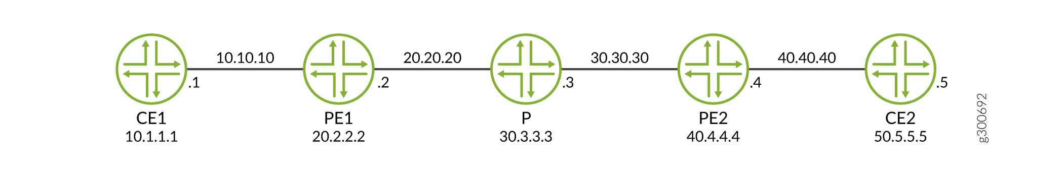
この例では、BGPおよびMPLSスタティックラベルスイッチパスを設定することで、VPNトラフィックがPE間のv4 MPLSトンネルを通過する様子を示しています。
必要条件
この例では、以下のハードウェアとソフトウェアのコンポーネントを使用しています。
-
Ubuntuソフトウェアバージョン18.04
-
Linux カーネル バージョン 4.5 以降
-
cRPDソフトウェアリリースバージョン19.4R1以降
MPLS 転送用に静的 LSP を設定する前に、以下の基本コンポーネントをインストールしなければなりません。
-
cRPDインスタンスが作成されるホストOS上のMPLSモジュール。詳細については、「 ホスト OS で設定を構成する」を参照してください。
-
プロバイダーエッジルーター(PE1)、プロバイダールーター(P)、プロバイダエッジルーター(PE2)。インストールについては、 DockerにcRPDをインストールするを参照してください。
概要
この例では、PE1 はラベル エッジ ルーターまたは MPLS ネットワークへのイングレス ノードとして機能し、ラベルを付加することでパケットをカプセル化します。P は、MPLS ネットワーク内のラベルを使用して MPLS パケットを転送するラベル スイッチング ルーターとして機能します。
MPLS を設定するには、まずイングレスルーターとトランジットルーターに 1 つ以上の名前付きパスを作成する必要があります。各パスに対して、パスの一部またはすべてのトランジットルーターを指定できます。
MPLS の LSP(スタティック ラベルスイッチ パス)の設定は、個々のルーターのスタティック ルートの設定と同様です。
構成
cRPDでMPLSの静的LSPを設定するには:
PE1ルーターの設定
手順
静的LSPを設定するには。
-
テーブル inet.0 と mpls.0 を作成します。
[edit routing-options] user@crpd1# set rib inet.0 user@crpd1# set rib mpls.0 user@crpd1# set router-id 20.2.2.2 -
BGP セッションを設定します。
[edit protocols bgp group VPN] user@crpd1# set type internal local-address 20.2.2.2 family inet-vpn unicast user@crpd1# set local-as 5 user@crpd1# set neighbor 40.4.4.4 family inet-vpn unicast -
静的ラベル範囲とイングレス静的LSPパラメータを設定します。
[edit protocols mpls] user@crpd1# set interface all user@crpd1# set label-range static-label-range 1000000 1048575 user@crpd1# set static-label-switched-path pe2 ingress install 40.4.4.4/32 active user@crpd1# set static-label-switched-path pe2 ingress to 40.4.4.4 next-hop 20.20.20.2 push 1000001 -
イングレスPE2からの静的ルートを設定します。
[edit routing-options static] user@crpd1# set route 20.2.2.2/32 next-hop 20.20.20.2 user@crpd1# set route 40.4.4.4/32 static-lsp-next-hop pe2 -
PE1およびその他のルーティング インスタンスパラメータでVRFルーティング インスタンスを設定します。
[edit routing-instances vrfblue]
user@crpd1# set routing-options static route 10.1.1.1/32 next-hop 10.10.10.1
user@crpd1# set route-distinguisher 100:100
user@crpd1# set vrf-target target:100:100
user@crpd1# set interface all
業績
設定モードから、PE1で show protocols bgp コマンドと run show configuration protocols mpls コマンドを入力して設定を確認します。出力結果に意図した設定内容が表示されない場合は、この例の設定手順を繰り返して設定を修正します。
user@crpd1# show protocols bgp
group VPN {
    type internal;
    local-address 20.2.2.2;
    family inet-vpn {
        unicast;
    }
    local-as 5;
    neighbor 40.4.4.4 {
        family inet-vpn {
            unicast;
        }
    }
}
user@crpd1# run show configuration protocols mpls
interface all;
static-label-switched-path pe2 {
    ingress {
        next-hop 20.20.20.3;
        to 40.4.4.4;
        push 1000001;
    }
}
デバイスの設定が完了したら、設定モードから コミットを入力します。
プロバイダー P ルーターの設定。
手順
静的LSPを設定するには。
-
ルーターPのルーターIDを設定します。
[edit routing-options] user@crpd2# set rib mpls.0 user@crpd2# set router-id 30.3.3.3 -
スワップおよびポップラベル用のトランジット静的LSPを設定します。
[edit protocols mpls]
user@crpd2# set label-range static-label-range 1000000 1048575
user@crpd2# set static-label-switched-path pe2 transit 1000001 next-hop 30.30.30.4 swap 1000002
user@crpd2# set static-label-switched-path pe1 transit 1000003 next-hop 20.20.20.2 swap 1000004
user@crpd2# set static-label-switched-path pe2 transit 1000001 pop next-hop 30.30.30.4
user@crpd2# set static-label-switched-path pe1 transit 1000003 pop next-hop 20.20.20.2
業績
設定モードから、P に show protocols bgp、 run show configuration protocols mpls、 run show mpls interface コマンドを入力して設定を確認します。出力結果に意図した設定内容が表示されない場合は、この例の設定手順を繰り返して設定を修正します。
user@crpd2# run show configuration protocols mpls
interface all;
static-label-switched-path pe1 {
    transit 1000003 {
        next-hop 20.20.20.2;
        swap 1000004;
    }
}
static-label-switched-path pe2 {
    transit 1000001 {
        next-hop 30.30.30.4;
        swap 1000002;
    }
}
デバイスの設定が完了したら、設定モードから コミットを入力します。
PE2ルーターの設定
手順
PE2でMPLSの静的LSPを設定するには:
-
BGP セッションを設定します。
[edit protocols bgp group VPN ] user@crpd3# set type internal local-address 40.4.4.4 family inet-vpn unicast user@crpd3# set local-as 5 user@crpd3# set neighbor 20.2.2.2 family inet-vpn unicast -
イングレス静的LSPパラメーターを設定します。
[edit protocols mpls ] user@crpd3# set interface all user@crpd3# set label-range static-label-range 1000000 1048575 user@crpd3# set static-label-switched-path pe1 ingress install 20.2.2.2/32 active user@crpd3# set static-label-switched-path pe1 ingress to 20.2.2.2 next-hop 30.30.30.4 push 1000003 -
ルーターIDとイングレスPE1からの静的ルートを設定します。
[edit routing-options] user@crpd3# set rib inet.0 user@crpd3# set router-id 40.4.4.4 user@crpd3# set static route 40.4.4.4/32 next-hop 30.30.30.4 user@crpd3# set static route 20.2.2.2/32 static-lsp-next-hop pe1 -
PE2およびその他のルーティング インスタンスパラメータでVRFルーティング インスタンスを設定します。
[edit routing-instances vrfblue]
user@crpd3# set routing-options static route 50.5.5.5/32 next-hop 40.40.40.5
user@crpd3# set route-distinguisher 100:100
user@crpd3# set vrf-target target:100:100
user@crpd3# set interface all
業績
設定モードから、PE2で run show configuration protocols mpls コマンドと run show mpls interface コマンドを入力して設定を確認します。出力結果に意図した設定内容が表示されない場合は、この例の設定手順を繰り返して設定を修正します。
user@crpd3# show protocols bgp
group VPN {
    type internal;
    local-address 40.4.4.4;
    family inet-vpn {
        unicast;
    }
    local-as 5;
    neighbor 20.2.2.2 {
        family inet-vpn {
            unicast;
        }
    }
}
user@crpd3# run show configuration protocols mpls
interface all;
static-label-switched-path pe2 {
    ingress {
        next-hop 20.20.20.3;
        to 40.4.4.4;
        push 1000001;
    }
}
デバイスの設定が完了したら、設定モードから コミットを入力します。
検証
PE1でMPLS転送を確認する
目的
PE1でMPLSの設定を確認するには。
アクション
動作モードから、 show route table vrfblue.inet.0 50.5.5.5 コマンドを入力します。
user@crpd1> show route table vrfblue.inet.0 50.5.5.5
vrfblue.inet.0: 5 destinations, 5 routes (5 active, 0 holddown, 0 hidden)
+ = Active Route, - = Last Active, * = Both

50.5.5.5/32         *[BGP/170] 00:01:03, localpref 100, from 40.4.4.4
                      AS path: I, validation-state: unverified
                    >  to 20.20.20.3 via pe1-p, Push 299776, Push 1000001(top)
動作モードから、 show mpls label usage コマンドを入力します。
user@crpd1> show mpls label usage
Label space Total   Available        Applications
LSI         999984  999983 (100.00%) BGP/LDP VPLS with no-tunnel-services, BGP L3VPN with vrf-table-label
Block       999984  999983 (100.00%) BGP/LDP VPLS with tunnel-services, BGP L2VPN
Dynamic     999984  999983 (100.00%) RSVP, LDP, PW, L3VPN, RSVP-P2MP, LDP-P2MP, MVPN, EVPN, BGP
Static      48576   48576  (100.00%) Static LSP, Static PW
Effective Ranges
Range name  Shared with Start   End
Dynamic     16      999999
Static      1000000 1048575
Configured Ranges
Range name  Shared with Start   End
Dynamic     16      999999
Static      1000000 1048575
動作モードから、 show mpls static-lsp コマンドを入力します。
user@crpd1> show mpls static-lsp
Ingress LSPs:
LSPname                             To              State
pe2                                 40.4.4.4         Up
Total 1, displayed 1, Up 1, Down 0

Transit LSPs:
Total 0, displayed 0, Up 0, Down 0

Bypass LSPs:
Total 0, displayed 0, Up 0, Down 0

Segment LSPs:
Total 0, displayed 0, Up 0, Down 0
動作モードから、 show route table inet.3 コマンドを入力します。
user@crpd1> show route table inet.3
inet.3: 1 destinations, 1 routes (1 active, 0 holddown, 0 hidden)
+ = Active Route, - = Last Active, * = Both

40.4.4.4/32         *[MPLS/6/1] 00:04:44, metric 0
                    >  to 20.20.20.3 via pe1-p, Push 1000001
動作モードから、 show route table mpls.0 コマンドを入力します。
user@crpd1> show route table mpls.0
mpls.0: 6 destinations, 6 routes (6 active, 0 holddown, 0 hidden)
+ = Active Route, - = Last Active, * = Both

0                  *[MPLS/0] 00:15:45, metric 1
                       Receive
1                  *[MPLS/0] 00:15:45, metric 1
                       Receive
2                  *[MPLS/0] 00:15:45, metric 1
                       Receive
13                 *[MPLS/0] 00:15:45, metric 1
                       Receive
299776             *[VPN/170] 00:06:32
                    >  to 10.10.10.1 via pe1-ce1, Pop
299776(S=0)        *[VPN/170] 00:06:32
                    >  to 10.10.10.1 via pe1-ce1, Pop
動作モードから、 ip route list table 5 50.5.5.5 コマンドを入力します。
user@crpd1> ip route list table 5 50.5.5.5
50.5.5.5 encap mpls 1000001/299776 via 20.20.20.3 dev pe1-p proto 22
動作モードから、 ip -f mpls route コマンドを入力します。
user@crpd1> ip -f mpls route
299776 via inet 10.10.10.1 dev pe1-ce1 proto 22
PでのMPLS転送の確認
目的
P 上の MPLS の設定を検証するには、次の手順に従います。
アクション
シェル モードから、 show route table mpls.0 コマンドを入力します。
user@crpd2> show route table mpls.0
mpls.0: 10 destinations, 10 routes (10 active, 0 holddown, 0 hidden)
+ = Active Route, - = Last Active, * = Both

0                  *[MPLS/0] 00:00:11, metric 1
                       Receive
1                  *[MPLS/0] 00:00:11, metric 1
                       Receive
2                  *[MPLS/0] 00:00:11, metric 1
                       Receive
13                 *[MPLS/0] 00:00:11, metric 1
                       Receive
299776             *[VPN/170] 00:00:05
                    >  to 20.20.20.2 via p-pe1, Pop
299776(S=0)        *[VPN/170] 00:00:05
                    >  to 20.20.20.2 via p-pe1, Pop
299792             *[VPN/170] 00:00:05
                    >  to 30.30.30.4 via p-pe2, Pop
299792(S=0)        *[VPN/170] 00:00:05
                    >  to 30.30.30.4 via p-pe2, Pop
1000001            *[MPLS/6] 00:00:11, metric 1
                    >  to 30.30.30.4 via p-pe2, Swap 1000002
1000003            *[MPLS/6] 00:00:11, metric 1
                    >  to 20.20.20.2 via p-pe1, Swap 1000004
user@crpd2> show mpls static-lsp
Ingress LSPs:
Total 0, displayed 0, Up 0, Down 0

Transit LSPs:
LSPname                             Incoming-label  State
pe1                                 1000003         Up
pe2                                 1000001         Up
Total 2, displayed 2, Up 2, Down 0

Bypass LSPs:
Total 0, displayed 0, Up 0, Down 0

Segment LSPs:
Total 0, displayed 0, Up 0, Down 0
bashシェルモードから、 ip -f mpls route コマンドを入力します。
user@crpd2:/# ip -f mpls route
299776 via inet 20.20.20.2 dev p-pe1 proto 22
299792 via inet 30.30.30.4 dev p-pe2 proto 22
1000001 as to 1000002 via inet 30.30.30.4 dev p-pe2 proto 22
1000003 as to 1000004 via inet 20.20.20.2 dev p-pe1 proto 22
PE2 での MPLS 転送の検証
目的
P 上の MPLS の設定を検証するには、次の手順に従います。
アクション
シェル モードから、 show route table vrfblue.inet.0 10.1.1.1 コマンドを入力します。
user@crpd3> show route table vrfblue.inet.0 10.1.1.1
vrfblue.inet.0: 5 destinations, 5 routes (5 active, 0 holddown, 0 hidden)
+ = Active Route, - = Last Active, * = Both

10.1.1.1/32         *[BGP/170] 00:03:00, localpref 100, from 2.2.2.2
                      AS path: I, validation-state: unverified
                    >  to 30.30.30.3 via pe2-p, Push 299776, Push 1000003(top)
user@crpd3> show mpls static-lsp
Ingress LSPs:
LSPname                             To              State
pe1                                 20.2.2.2         Up
Total 1, displayed 1, Up 1, Down 0

Transit LSPs:
LSPname                             Incoming-label  State
pe2                                 1000002         Dn
Total 1, displayed 1, Up 0, Down 1

Bypass LSPs:
Total 0, displayed 0, Up 0, Down 0

Segment LSPs:
Total 0, displayed 0, Up 0, Down 0
user@crpd3> show route table mpls.0
mpls.0: 6 destinations, 6 routes (6 active, 0 holddown, 0 hidden)
+ = Active Route, - = Last Active, * = Both

0                  *[MPLS/0] 00:17:31, metric 1
                       Receive
1                  *[MPLS/0] 00:17:31, metric 1
                       Receive
2                  *[MPLS/0] 00:17:31, metric 1
                       Receive
13                 *[MPLS/0] 00:17:31, metric 1
                       Receive
299776             *[VPN/170] 00:03:07
                    >  to 40.40.40.5 via pe2-ce2, Pop
299776(S=0)        *[VPN/170] 00:03:07
                    >  to 40.40.40.5 via pe2-ce2, Pop
bashシェルモードから、 ip -f mpls route コマンドを入力します。
user@crpd3:/# ip -f mpls route
299776 via inet 40.40.40.5 dev pe2-ce2 proto 22
bashシェルモードから、 ip route list table 5 10.1.1.1 コマンドを入力します。
user@crpd3:/# ip route list table 5 10.1.1.1
10.1.1.1 encap mpls 1000003/299776 via 30.30.30.3 dev pe2-p proto 22
意味
PE 間の静的 LSP がすべてのデバイスで稼働しており、対応するルート テーブル inet.o と inet.3 、および Linux FIB にルートが入力されていることを確認できます。