cRPDでのレイヤー3オーバーレイのサポート
概要
仮想ルーティングおよび転送(VRF)インスタンスは、オーバーレイ機能を提供するために、MPLSおよびマルチプロトコルBGPのサポートとともにcRPDでサポートされています。
ルーティング インスタンスは、ルーティング テーブル、インターフェイス、およびルーティング プロトコル パラメータの集合です。レイヤー 3 VPN を実装するには、VPN ごとに 1 つのルーティング インスタンスを構成します。VRF は Linux カーネル内のネットワーク デバイスであり、デバイスは table-id に関連付けられています。ルーティングインスタンスは、PEルーターでのみ設定します。Linux ネットワークで VRF を作成できます。VRF デバイスの実装は、レイヤー 3 以降にのみ影響します。各 VPN ルーティング インスタンスは、次のコンポーネントで構成されています。
VRF テーブル:各 PE ルーターで、VPN ごとに 1 つの VRF テーブルを設定します。
ポリシー ルール:VRF テーブルへのルートのインポートと VRF テーブルからのルートのエクスポートを制御します。
CE ルーターから VRF テーブルにルートをインストールする 1 つ以上のルーティング プロトコル—BGP、OSPF、および RIP ルーティング プロトコルを使用することができ、スタティック ルートも使用できます。
VRFデバイスが作成されると、ルーティングテーブルに関連付けられます。スレーブ デバイスを介して VRF に着信するパケットは、VRF デバイスに関連付けられたルーティングテーブルで検索されます。同様に、エグレス ルーティング ルールは、実際のインターフェイスでパケットを送信する前に VRF ドライバに送信するために使用されます。
VRFは、VRFの独立した転送テーブルに基づいて、ルートを管理し、トラフィックを転送するために使用されます。RPD は、タイプ vrf のルーティング インスタンスごとに複数のルーティング テーブルを作成します。テーブルは、各家族の住所ごとに 1 つです。VPN に参加している各 PE ルーターで、各 VPN のルーティング インスタンスを設定する必要があります。ルーティングインスタンスは、 [edit routing-instances] 階層を使用して設定できます。タイプ vrf のルーティング インスタンスは、cRPDでのみサポートされています。
[edit routing-instances routing-instance-name protocols]階層を使用して、VRF の下に BFD、BGP、IS-IS、OSPF バージョン 2(OSPF)、OSPF バージョン 3(OSPFv3)、および ICMP ルーター ディスカバリの複数のインスタンスを作成できます。edit routing-instances instance-name routing-options階層を使用してプロトコル非依存型ルーティングを設定できます。
レイヤー3オーバーレイは、cRPDで次のトンネリングプロトコルをサポートしています。
inet.3のスタティックルート
BGP ラベル付きユニキャスト
GRE トンネリング
MPLS 静的 LSP
プログラマブルRPD APIを使用してプログラムされたルート
MPLS対応インターフェイスでのdirect-ebgp-peering
VRFの下でのインターフェイスの設定
デバイスの奴隷化はRPDによって行われます。つまり、ルーティング インスタンスで設定されたインターフェイスは、カーネルに送信されたnetlinkメッセージを使用してRPDによってvrfデバイスに移行(奴隷化)されます。
インターフェイスがタイプ vrf のルーティング インスタンスで設定されている場合、そのようなリンクがカーネルから学習され、リンクが正しいテーブルに関連付けられていない場合、RPD はリンクをスレーブするためにネットリンク通知を送信します。リンクが存在しない場合、またはRPDがリンクについて学習していない場合、リンクが作成されるかRPDがそれについて学習するたびに、リンクは設定に基づいて正しくスレーブ化されます。
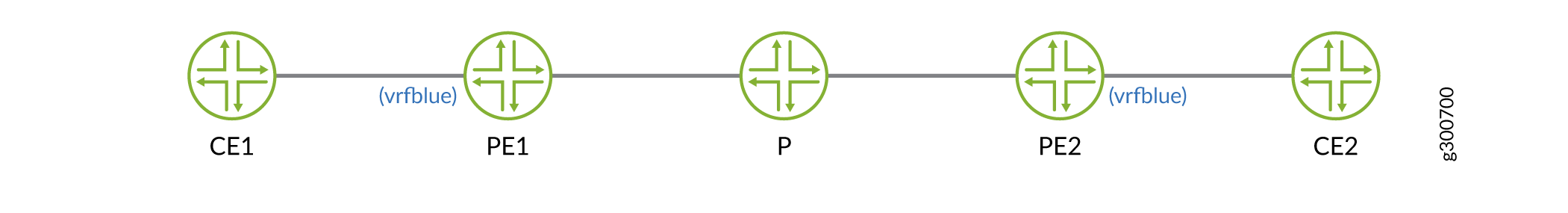
例:cRPDインスタンスでのレイヤー3 VPN(VRF)の設定
この例では、PE ルーターとルート リフレクターで VPNv4 ルート解決を行う例では、PE ルーターに、VRF テーブルへのルートのインポートと VRF テーブルからのルートのエクスポートを制御する特定のポリシーと、BGP ラベル付きユニキャストを使用して学習したネクストホップを設定します。この例では、トラフィックはCE1からCE2に流れます。
必要条件
この例では、以下のハードウェアとソフトウェアのコンポーネントを使用しています。
-
Ubuntuソフトウェアバージョン18.04
-
Linux カーネル バージョン 4.5 以降
-
cRPDソフトウェアリリースバージョン19.4R1以降
レイヤー 3 VPN(VRF)を設定する前に、以下の基本コンポーネントをインストールする必要があります。
-
cRPDインスタンスが作成されるホストOS上のMPLSモジュール。詳細については、「 ホスト OS で設定を構成する」を参照してください。
-
プロバイダー エッジルーター(PE1)、プロバイダー ルーター(P)、およびプロバイダエッジルーター(PE2)。インストールについては、 Docker への cRPD のインストールを参照してください。
概要
VPNv4 ルート解決を設定するには、VPN に参加している各 PE ルーター上の各 VPN に対して VRF タイプのルーティング インスタンスを設定し、それにスタティック ルートを追加する必要があります。 static ステートメントは、 vrfblue.inet.0 ルーティングテーブルにインストールされる静的ルートを設定します。Linux カーネルで作成されたすべての VRF デバイスに対応するループバック インターフェイスまたはデバイスはありません。ただし、ループバックホストアドレスはVRFデバイスに直接追加され、RPDで学習できます。
構成
BGP LUによるPE1ルーターの設定
手順
次の例では、設定階層のいくつかのレベルに移動する必要があります。
-
テーブル mpls.0 を作成します。
user@crpd1# set routing-options rib mpls.0 -
ルートを受け入れるポリシーを設定します。
[edit policy-options policy-statement] user@crpd1# set EXPORT_LO term 10 from route-filter 10.2.2.2/32 exact user@crpd1# set EXPORT_LO term 10 then accept user@crpd1# set NH_SELF term 10 then next-hop self -
PE1およびその他のルーティング インスタンスパラメータでVRFルーティング インスタンスを設定します。
[edit routing-instances vrfblue] user@crpd1# set routing-options static route 10.1.1.1/32 next-hop 10.10.10.1 user@crpd1# set instance-type vrf user@crpd1# set route-distinguisher 100:100 user@crpd1# set vrf-target target:100:100 -
ルーターIDを設定します。
user@crpd1# set routing-options router-id 10.2.2.2 -
BGP セッションを設定します。
[edit protocols bgp group] user@crpd1# set underlay type external family inet unicast user@crpd1# set underlay type external export EXPORT_LO neighbor 10.20.20.3 family inet labeled-unicast resolve-vpn user@crpd1# set underlay type external export EXPORT_LO neighbor 10.20.20.3 peer-as 65002 local-as 65001 user@crpd1# set VPN type internal local-address 10.2.2.2 family inet-vpn unicast user@crpd1# set VPN local-as 65005 user@crpd1# set VPN neighbor 10.4.4.4 family inet-vpn unicast -
MPLSでインターフェイスを設定します。
user@crpd1# set protocols mpls interface all
業績
設定モードから、 show protocols bgp コマンドと show routing-instances コマンドを入力して設定を確認します。出力結果に意図した設定内容が表示されない場合は、この例の設定手順を繰り返して設定を修正します。
user@crpd1# show routing-instances
vrfblue {
    routing-options {
        static {
            route 10.1.1.1/32 next-hop 10.10.10.1;
        }
    }
    instance-type vrf;
    route-distinguisher 100:100;
    vrf-target target:100:100;
}
user@crpd1# show protocols bgp
group underlay {
    type external;
    family inet {
        unicast;
    }
    export EXPORT_LO;
    neighbor 10.20.20.3 {
        family inet {
            labeled-unicast {
                resolve-vpn;
            }
        }
        peer-as 65002;
        local-as 65001;
    }
    neighbor 10.20.20.2 {
        family inet {
            labeled-unicast {
                resolve-vpn;
            }
        }
        peer-as 65001;
        local-as 65002;
    }
    neighbor 10.30.30.4 {
        family inet {
            labeled-unicast {
                resolve-vpn;
            }
        }
        peer-as 65003;
        local-as 65004;
    }
}
group VPN {
    type internal;
    local-address 10.2.2.2;
    family inet-vpn {
        unicast;
    }
    local-as 65005;
    neighbor 10.4.4.4 {
        family inet-vpn {
            unicast;
        }
    }
}
デバイスの設定が完了したら、設定モードから コミットを入力します。
BGP LU による P ルーターの設定
手順
次の例では、設定階層のいくつかのレベルに移動する必要があります。
-
テーブル mpls.0 を作成します。
user@crpd2# set routing-options rib mpls.0 -
ルートを受け入れるポリシーを設定します。
[edit policy-options policy-statement] user@crpd2# set EXPORT_LO term 10 from route-filter 10.3.3.3/32 exact user@crpd2# set EXPORT_LO term 10 then accept user@crpd2# set NH_SELF term 10 then next-hop self -
BGP セッションを設定します。
[edit protocols bgp group] user@crpd2# set underlay type external export EXPORT_LO neighbor 10.20.20.2 family inet labeled-unicast resolve-vpn user@crpd2# set underlay type external export EXPORT_LO neighbor 10.20.20.2 peer-as 65001 user@crpd2# set underlay type external export EXPORT_LO neighbor 10.20.20.2 local-as 65002 user@crpd2# set underlay type external export EXPORT_LO neighbor 10.30.30.4 family inet labeled-unicast resolve-vpn user@crpd2# set underlay type external export EXPORT_LO neighbor 10.30.30.4 peer-as 65003 user@crpd2# set underlay type external export EXPORT_LO neighbor 10.30.30.4 local-as 65004 -
ルーターIDを設定します。
user@crpd2# set routing-options router-id 10.3.3.3 -
MPLSでインターフェイスを設定します。
user@crpd2# set protocols mpls interface all
業績
設定モードから、 show protocols bgp コマンドと show policy-options コマンドを入力して設定を確認します。出力結果に意図した設定内容が表示されない場合は、この例の手順を繰り返して設定を修正します。
user@crpd2# show protocols bgp
group underlay {
    type external;
    export EXPORT_LO;
    neighbor 10.20.20.2 {
        family inet {
            labeled-unicast {
                resolve-vpn;
            }
        }
        peer-as 65001;
        local-as 65002;
    }
    neighbor 10.30.30.4 {
        family inet {
            labeled-unicast {
                resolve-vpn;
            }
        }
        peer-as 65003;
        local-as 65004;
    }
}
user@crpd2# show policy-options
policy-statement EXPORT_LO {
    term 10 {
        from {
            route-filter 10.3.3.3/32 exact;
        }
        then accept;
    }
}
policy-statement NH_SELF {
    term 10 {
        then {
            next-hop self;
        }
    }
}
BGP LUによるPE2ルーターの設定
手順
次の例では、設定階層のいくつかのレベルに移動する必要があります。
-
テーブル mpls.0 を作成します。
user@crpd3# set routing-options rib mpls.0 -
ルートを受け入れるポリシーを設定します。
[edit policy-options policy-statement] user@crpd3# set EXPORT_LO term 10 from route-filter 10.4.4.4/32 exact user@crpd3# set EXPORT_LO term 10 then accept user@crpd3# set NH_SELF term 10 then next-hop self -
PE2およびその他のルーティング インスタンスパラメータでVRFルーティング インスタンスを設定します。
[edit routing-instances vrfblue] user@crpd3# set routing-options static route 10.5.5.5/32 next-hop 10.40.40.5 user@crpd3# set instance-type vrf user@crpd3# set route-distinguisher 100:100 user@crpd3# set vrf-target target:100:100 user@crpd3# set interface all -
BGP セッションを設定します。
[edit protocols bgp group] user@crpd3# set underlay type external export EXPORT_LO neighbor 10.30.30.3 family inet labeled-unicast resolve-vpn user@crpd3# set underlay type external export EXPORT_LO neighbor 10.30.30.3 peer-as 65004 user@crpd3# set underlay type external export EXPORT_LO neighbor 10.30.30.3 local-as 65003 user@crpd3# set VPN type internal local-address 10.4.4.4 family inet-vpn unicast user@crpd3# set VPN local-as 65005 user@crpd3# set VPN neighbor 10.2.2.2 family inet-vpn unicast -
ルーターIDを設定します。
user@crpd3# set routing-options router-id 10.4.4.4 -
MPLSでインターフェイスを設定します。
user@crpd3# set protocols mpls interface all
業績
設定モードから、 show protocols bgp コマンドと show routing-instances コマンドを入力して設定を確認します。出力結果に意図した設定内容が表示されない場合は、この例の手順を繰り返して設定を修正します。
user@crpd3# show protocols bgp
group underlay {
    export EXPORT_LO;
    neighbor 10.30.30.3 {
        family inet {
            labeled-unicast {
                resolve-vpn;
            }
        }
        peer-as 65004;
        local-as 65003;
    }
}
group VPN {
    type internal;
    local-address 10.4.4.4;
    family inet-vpn {
        unicast;
    }
    local-as 65005;
    neighbor 10.2.2.2 {
        family inet-vpn {
            unicast;
        }
    }
}
user@crpd3# show routing-instances
vrfblue {
    routing-options {
        static {
            route 10.5.5.5/32 next-hop 10.40.40.5;
        }
    }
    interface all;
    instance-type vrf;
    route-distinguisher 100:100;
    vrf-target target:100:100;
}
検証
PE1でのVPNv4解決の確認
目的
PE1でVPNv4ルートを検証するには:
アクション
動作モードから、 show route table vrfblue.inet.0 10.5.5.5 コマンドを入力します。
user@crpd1> show route table vrfblue.inet.0 10.5.5.5
vrfblue.inet.0: 7 destinations, 7 routes (7 active, 0 holddown, 0 hidden)
+ = Active Route, - = Last Active, * = Both

10.5.5.5/32         *[BGP/170] 00:00:14, localpref 100, from 10.4.4.4
                      AS path: I, validation-state: unverified
                    >  to 10.20.20.3 via pe1-p, Push 299808, Push 299792(top)
動作モードから、 show route table mpls.0 コマンドを入力します。
user@crpd1> show route table mpls.0
mpls.0: 3 destinations, 3 routes (3 active, 0 holddown, 0 hidden)
+ = Active Route, - = Last Active, * = Both

299808             *[VPN/170] 00:01:45
                    >  to 10.10.10.1 via pe1-ce1, Pop
299808(S=0)        *[VPN/170] 00:01:45
                    >  to 10.10.10.1 via pe1-ce1, Pop
299824             *[VPN/170] 00:01:45
                       receive table vrfblue.inet.0, Pop
bash モードから、 ip route list table 5 5.5.5.5 コマンドを入力します。
user@crpd1> ip route list table 5 10.5.5.5
10.5.5.5 encap mpls 299792/299808 via 10.20.20.3 dev pe1-p proto 22
bash モードから、 ip -f mpls route コマンドを入力します。
user@crpd1> ip -f mpls route
299808 via inet 10.10.10.1 dev pe1-ce1 proto 22
意味
PE1には、ネクストホップ10.4.4.4でPE2から学習したCE2への vrfblue.inet.0 ルートがあり、これはPルーターからのBGP LUを使用して解決されていることがわかります。
P での BGP LU の検証
目的
PでVPNv4ルートを検証するには:
アクション
bash モードから、 ip -f mpls route show コマンドを入力します。
user@crpd2> ip -f mpls route show
299776 via inet 10.20.20.2 dev p-pe1 proto 22
299792 via inet 10.30.30.4 dev p-pe2 proto 22
動作モードから、 show route table mpls.0 コマンドを入力します。
user@crpd2> show route table mpls.0
mpls.0: 8 destinations, 8 routes (8 active, 0 holddown, 0 hidden)
+ = Active Route, - = Last Active, * = Both

0                  *[MPLS/0] 01:40:42, metric 1
                       Receive
1                  *[MPLS/0] 01:40:42, metric 1
                       Receive
2                  *[MPLS/0] 01:40:42, metric 1
                       Receive
13                 *[MPLS/0] 01:40:42, metric 1
                       Receive
299776             *[VPN/170] 01:19:24
                    >  to 10.20.20.2 via p-pe1, Pop
299776(S=0)        *[ VPN/170] 01:19:24
                    >  to 10.20.20.2 via p-pe1, Pop
299792             *[VPN/170] 01:19:20
                    >  to 10.30.30.4 via p-pe2, Pop
299792(S=0)        *[VPN/170] 01:19:20
                    >  to 10.30.30.4 via p-pe2, Pop
意味
PからPE1およびPからPE2へのMPLSおよびVPNルートを表示できます。
PE2 での VPNv4 解決の検証
目的
PE2でVPNv4ルートを検証するには:
アクション
動作モードから、 show route table vrfblue.inet.0 10.1.1.1 コマンドを入力します。
user@crpd3> show route table vrfblue.inet.0 10.1.1.1
vrfblue.inet.0: 7 destinations, 7 routes (7 active, 0 holddown, 0 hidden)
+ = Active Route, - = Last Active, * = Both

10.1.1.1/32         *[BGP/170] 00:00:26, localpref 100, from 10.2.2.2
                      AS path: I, validation-state: unverified
                    >  to 10.30.30.3 via pe2-p, Push 299808, Push 299776(top)
動作モードから、 show route table mpls.0 コマンドを入力します。
user@crpd3> show route table mpls.0
mpls.0: 7 destinations, 7 routes (7 active, 0 holddown, 0 hidden)
+ = Active Route, - = Last Active, * = Both

0                  *[MPLS/0] 01:34:39, metric 1
                       Receive
1                  *[MPLS/0] 01:34:39, metric 1
                       Receive
2                  *[MPLS/0] 01:34:39, metric 1
                       Receive
13                 *[MPLS/0] 01:34:39, metric 1
                       Receive
299808             *[VPN/170] 00:00:43
                    >  to 10.40.40.5 via pe2-ce2, Pop
299808(S=0)        *[VPN/170] 00:00:43
                    >  to 10.40.40.5 via pe2-ce2, Pop
299824             *[VPN/170] 00:00:43
                       receive table vrfblue.inet.0, Pop
bash モードから、 ip route list table 5 10.1.1.1 コマンドを入力します。
user@crpd3> ip route list table 5 10.1.1.1
10.1.1.1 encap mpls 299776/299808 via 10.30.30.3 dev pe2-p proto 22
bash モードから、 ip -f mpls route コマンドを入力します。
user@crpd3> ip -f mpls route
299808 via inet 10.40.40.5 dev pe2-ce2 proto 22
意味
PE2 ルーターでは、PE1 は、ネクストホップを 10.2.2.2 とする VPNv4 プレフィックスとして 10.1.1.1 に関する BGP LU を使用して vrfblue.inet.0 VRF テーブルのルートを表示します。