
ConnectorOps トポロジの例を設定する
次の手順を使用して、このApstra ConnectorOpsセットアップガイドで使用するトポロジーを正確に設定します。ファブリックの配線や設計を構成する方法はさまざまですが、これはほんの一例です。このプロセスで実行されるすべての設定は、このトポロジーに固有です。
独自のトポロジーを使用している場合は、ConnectorOpsがApstraでSRX構成をレンダリングするために必要なすべての 前提条件 を参照してください。大まかな手順:ファブリックのルーティングポリシーを作成するには
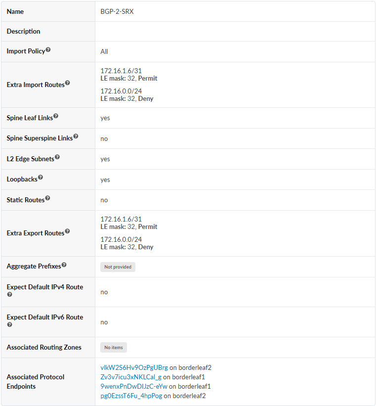
- 以下のパラメーターを使用してルーティングポリシーを設定します。
SRXとボーダーリーフ間の接続テンプレートを作成して割り当てるには
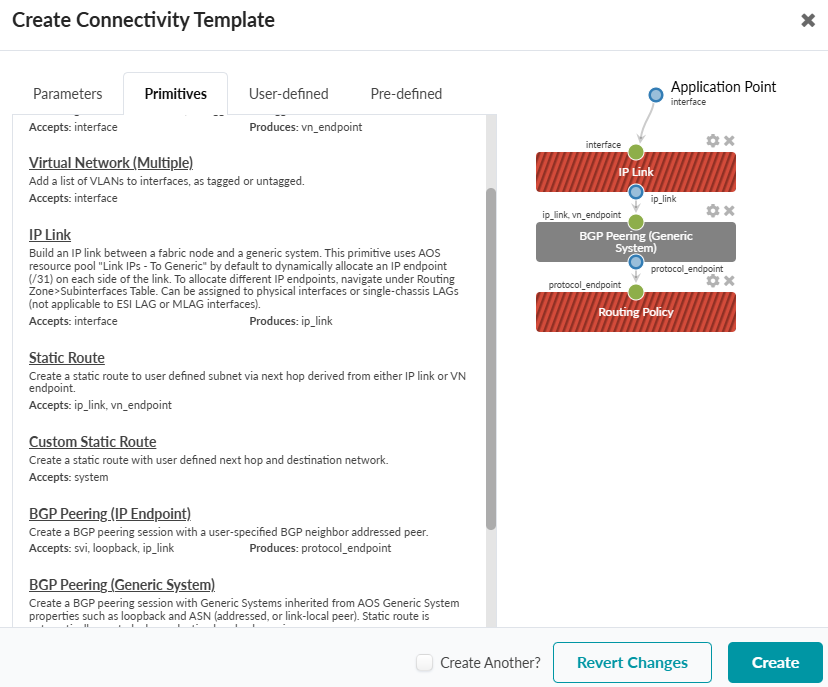
- IPリンク、BGPピアリング(汎用システム)、ルーティングポリシーを選択します。
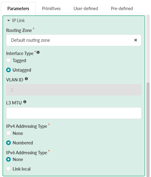
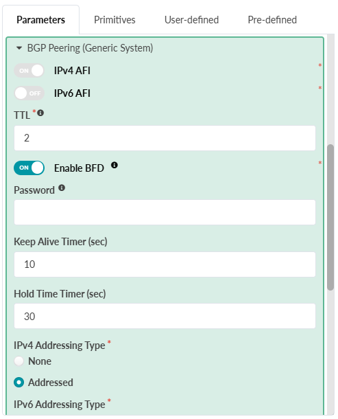
- パラメータータブを選択し、各プリミティブを以下のパラメーターで設定します。
-
IPリンク
-
BGPピアリング(汎用システム)
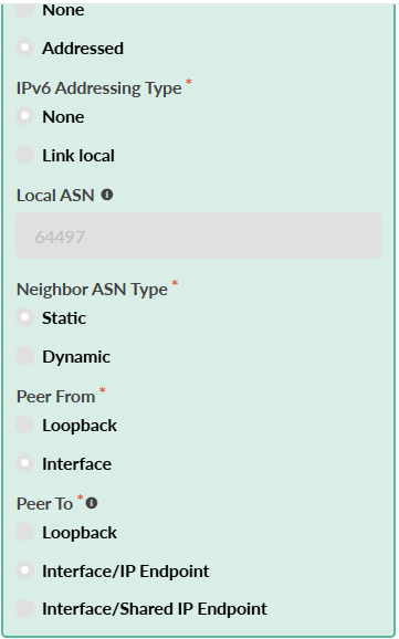
-
ルーティングポリシー:ルーティングポリシー
-
- 接続テンプレートを選択し、 割り当て ボタンをクリックします。
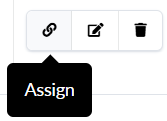
- 割り当てをクリックします。
新しいBGPピアを確認するには、 ステージング > 仮想 > ルーティングゾーン に移動し>デフォルトのルーティングゾーン> インターフェイス セクションを選択します。'
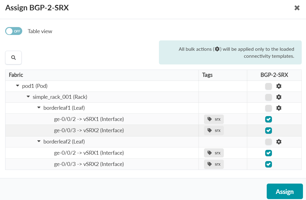
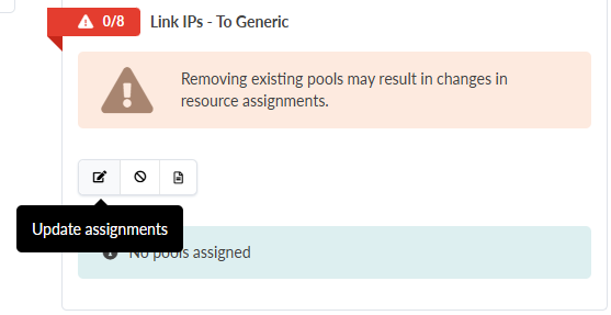
- 汎用システムへのリンクIPの割り当て
ステージング>仮想>プロトコルセッションで検証できます。
Apstraに外部(オーバーザトップ)ゲートウェイを作成し、それらを各SRXのファイアウォールとして指定するには
- 2. 以下のパラメーターを使用して、各SRXの外部ゲートウェイを設定します。
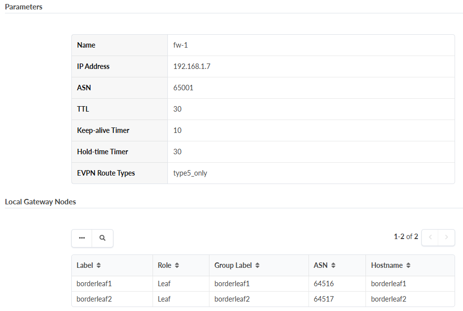
VNを作成し、ルーティングゾーンをノードに割り当てるには
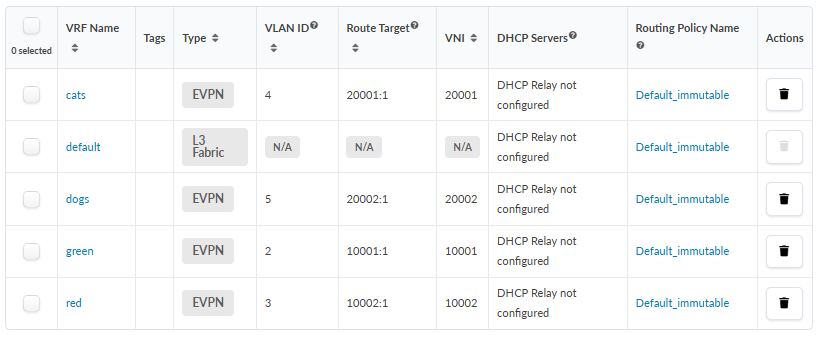
- ルーティングゾーンのリストが表示されるまで、このプロセスを繰り返します。以下に、ルーティングゾーンのリストの例を示します。
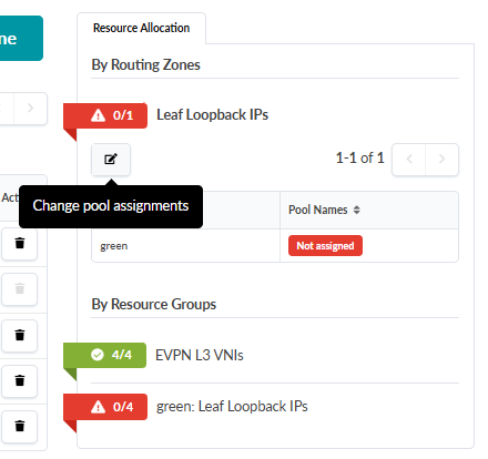
- 割り当てボタンをクリックして、ループバックIPアドレッシング用のIPプールを割り当てます。
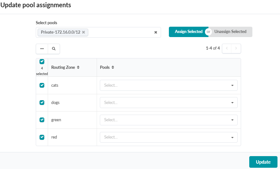
- 選択項目を割り当てを選択し、更新をクリックします。
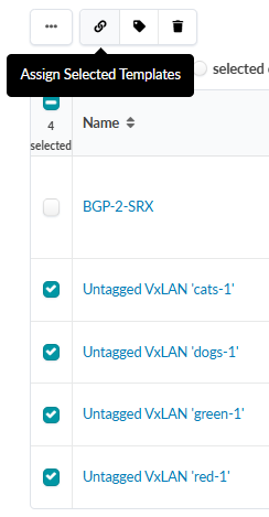
- リストから新しいVNを選択し、上部にある選択したテンプレートの割り当てボタンを選択します。
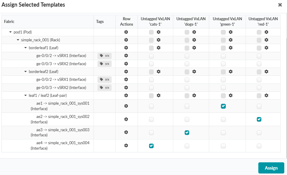
選択したテンプレートの割り当てウィンドウが表示されます。表の上部にある各VNの列に注目してください。
- 各VNを対応するインターフェイス(エンドポイント)に割り当てます。
以下の例は、指定されたVN割り当てを示しています。
セキュリティポリシーを設定するには
このエンドツーエンドルーティングのトポロジー例でSRXデバイスに適用されている正確なセキュリティポリシーは次のとおりです。
set groups COMMON security address-book global address FW-1 172.16.1.6/32
set groups COMMON security address-book global address FW-2-lo 172.16.1.7/32
set groups COMMON security address-book global address FW-2-ge-0-0-0 192.168.0.19/32
set groups COMMON security address-book global address FW-2-ge-0-0-1 192.168.0.23/32
set groups COMMON security address-book global address BGP-0 172.16.0.4/32
set groups COMMON security address-book global address BGP-1 172.16.0.5/32
set groups COMMON security address-book global address green 210.210.0.0/16
set groups COMMON security address-book global address red 200.200.0.0/16
set groups COMMON security address-book global address cats 221.221.0.0/16
set groups COMMON security address-book global address dogs 220.220.0.0/16
set groups COMMON security address-book global address-set FW-2 address FW-2-lo
set groups COMMON security address-book global address-set FW-2 address FW-2-ge-0-0-0
set groups COMMON security address-book global address-set FW-2 address FW-2-ge-0-0-1
set groups COMMON security policies from-zone evpn to-zone evpn policy HA-ICL match source-address FW-2
set groups COMMON security policies from-zone evpn to-zone evpn policy HA-ICL match destination-address FW-1
set groups COMMON security policies from-zone evpn to-zone evpn policy HA-ICL match application any
set groups COMMON security policies from-zone evpn to-zone evpn policy HA-ICL then permit
set groups COMMON security policies from-zone evpn to-zone evpn policy HA-ICL then log session-init
set groups COMMON security policies from-zone evpn to-zone evpn policy HA-ICL then log session-close
set groups COMMON security policies from-zone evpn to-zone evpn policy G2R match source-address green
set groups COMMON security policies from-zone evpn to-zone evpn policy G2R match destination-address red
set groups COMMON security policies from-zone evpn to-zone evpn policy G2R match application junos-ping
set groups COMMON security policies from-zone evpn to-zone evpn policy G2R match application junos-ssh
set groups COMMON security policies from-zone evpn to-zone evpn policy G2R match source-l3vpn-vrf-group GREEN
set groups COMMON security policies from-zone evpn to-zone evpn policy G2R match destination-l3vpn-vrf-group RED
set groups COMMON security policies from-zone evpn to-zone evpn policy G2R then permit
set groups COMMON security policies from-zone evpn to-zone evpn policy G2R then log session-init
set groups COMMON security policies from-zone evpn to-zone evpn policy G2R then log session-close
set groups COMMON security policies from-zone evpn to-zone evpn policy R2G match source-address red
set groups COMMON security policies from-zone evpn to-zone evpn policy R2G match destination-address green
set groups COMMON security policies from-zone evpn to-zone evpn policy R2G match application junos-http
set groups COMMON security policies from-zone evpn to-zone evpn policy R2G match application junos-ping
set groups COMMON security policies from-zone evpn to-zone evpn policy R2G match source-l3vpn-vrf-group RED
set groups COMMON security policies from-zone evpn to-zone evpn policy R2G match destination-l3vpn-vrf-group GREEN
set groups COMMON security policies from-zone evpn to-zone evpn policy R2G then permit
set groups COMMON security policies from-zone evpn to-zone evpn policy R2G then log session-init
set groups COMMON security policies from-zone evpn to-zone evpn policy R2G then log session-close
set groups COMMON security policies from-zone evpn to-zone evpn policy D2C match source-address dogs
set groups COMMON security policies from-zone evpn to-zone evpn policy D2C match destination-address cats
set groups COMMON security policies from-zone evpn to-zone evpn policy D2C match application any
set groups COMMON security policies from-zone evpn to-zone evpn policy D2C match source-l3vpn-vrf-group DOGS
set groups COMMON security policies from-zone evpn to-zone evpn policy D2C match destination-l3vpn-vrf-group CATS
set groups COMMON security policies from-zone evpn to-zone evpn policy D2C then permit
set groups COMMON security policies from-zone evpn to-zone evpn policy C2D match source-address cats
set groups COMMON security policies from-zone evpn to-zone evpn policy C2D match destination-address dogs
set groups COMMON security policies from-zone evpn to-zone evpn policy C2D match application junos-ping
set groups COMMON security policies from-zone evpn to-zone evpn policy C2D match source-l3vpn-vrf-group CATS
set groups COMMON security policies from-zone evpn to-zone evpn policy C2D match destination-l3vpn-vrf-group DOGS
set groups COMMON security policies from-zone evpn to-zone evpn policy C2D then permit
set groups COMMON security policies from-zone evpn to-zone evpn policy FINAL-EVPN-DENY match source-address any
set groups COMMON security policies from-zone evpn to-zone evpn policy FINAL-EVPN-DENY match destination-address any
set groups COMMON security policies from-zone evpn to-zone evpn policy FINAL-EVPN-DENY match application junos-vxlan
set groups COMMON security policies from-zone evpn to-zone evpn policy FINAL-EVPN-DENY then deny
set groups COMMON security policies from-zone evpn to-zone evpn policy infra description "control plane permit"
set groups COMMON security policies from-zone evpn to-zone evpn policy infra match source-address any
set groups COMMON security policies from-zone evpn to-zone evpn policy infra match destination-address any
set groups COMMON security policies from-zone evpn to-zone evpn policy infra match application junos-bgp
set groups COMMON security policies from-zone evpn to-zone evpn policy infra match application junos-ping
set groups COMMON security policies from-zone evpn to-zone evpn policy infra match application bfd-mhop
set groups COMMON security policies from-zone evpn to-zone evpn policy infra then permit
set groups COMMON security policies from-zone evpn to-zone evpn policy infra then log session-init
set groups COMMON security policies from-zone evpn to-zone evpn policy infra then log session-close
set groups COMMON security policies from-zone evpn to-zone untrust policy C2EXT match source-address cats
set groups COMMON security policies from-zone evpn to-zone untrust policy C2EXT match destination-address any
set groups COMMON security policies from-zone evpn to-zone untrust policy C2EXT match application junos-http
set groups COMMON security policies from-zone evpn to-zone untrust policy C2EXT match application junos-http-ext
set groups COMMON security policies from-zone evpn to-zone untrust policy C2EXT match application junos-https
set groups COMMON security policies from-zone evpn to-zone untrust policy C2EXT match application junos-dns-udp
set groups COMMON security policies from-zone evpn to-zone untrust policy C2EXT match application junos-dns-tcp
set groups COMMON security policies from-zone evpn to-zone untrust policy C2EXT match application junos-ping
set groups COMMON security policies from-zone evpn to-zone untrust policy C2EXT match source-l3vpn-vrf-group CATS
set groups COMMON security policies from-zone evpn to-zone untrust policy C2EXT then permit
set groups COMMON security policies global policy infra-reject-log description "final touch"
set groups COMMON security policies global policy infra-reject-log match source-address any
set groups COMMON security policies global policy infra-reject-log match destination-address any
set groups COMMON security policies global policy infra-reject-log match application any
set groups COMMON security policies global policy infra-reject-log then reject
set groups COMMON security policies global policy infra-reject-log then log session-init
set groups COMMON security policies global policy infra-reject-log then log session-close
set groups COMMON security l3vpn vrf-group GREEN vrf GREEN
set groups COMMON security l3vpn vrf-group RED vrf RED
set groups COMMON security l3vpn vrf-group CATS vrf CATS
set groups COMMON security l3vpn vrf-group DOGS vrf DOGS
set security policies pre-id-default-policy then log session-close
set security zones security-zone trust tcp-rst
set security zones security-zone untrust screen untrust-screen
set security zones security-zone evpn host-inbound-traffic system-services all
set security zones security-zone evpn host-inbound-traffic protocols all
set security zones security-zone evpn interfaces ge-0/0/0.0
set security zones security-zone evpn interfaces ge-0/0/1.0
set security zones security-zone evpn interfaces lo0.0
set apply-groups COMMON
このトポロジを設定したら、 ConnectorOpsの展開と接続の確認に進みます。