QFX5700ケーブル管理システム
QFX5700ケーブル管理システムは、以下のコンポーネントで構成されています。
-
ケーブルマネージャー
-
ケーブルマネージャーアセンブリ
-
盤
-
ロック機構
手記:
同じモデルのラインカードを6枚以上取り付ける場合は、必ずケーブルマネージャーアセンブリを取り付ける必要があります。
ケーブルマネージャーを使用すると、QFX5700スイッチにインストールされているRCBとFPCに接続された多数の光ファイバーおよび銅線ケーブルを管理できます。QFX5700シャーシの前面に取り付けられています。 図1 は、QFX5700ケーブルマネージャーを示しています。
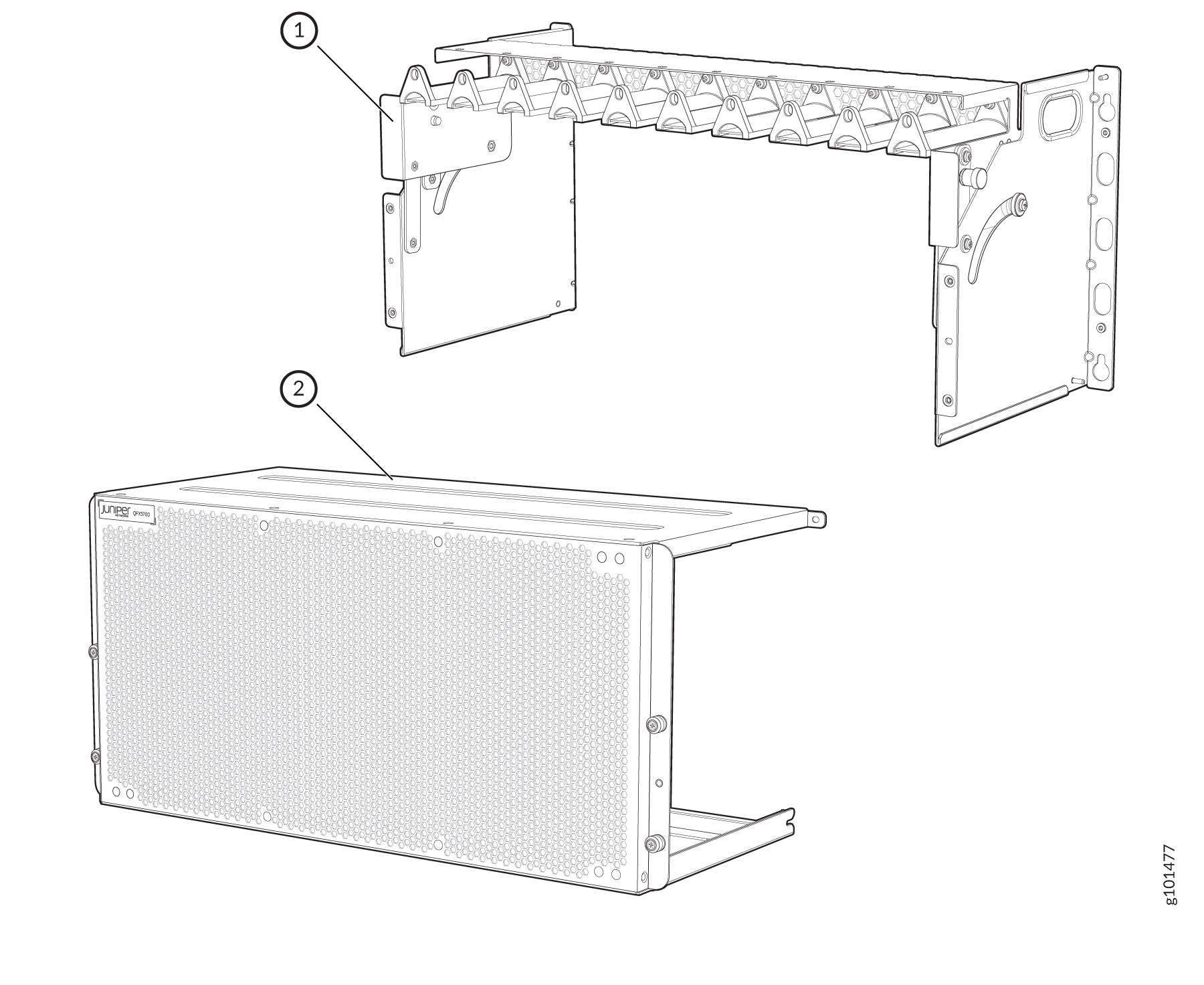
図2:EMIドア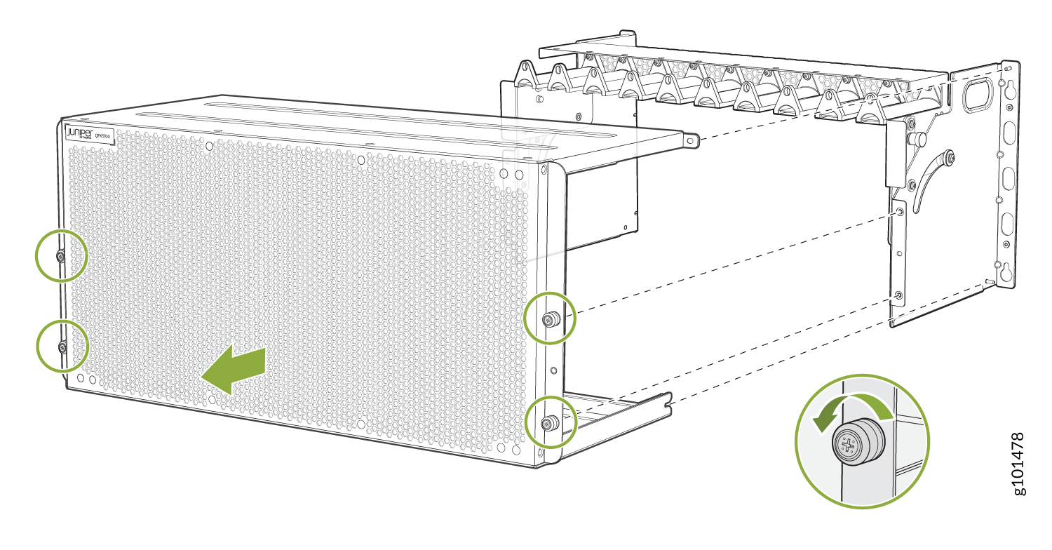 の取り外し
の取り外し
の取り外し
これで、ケーブルマネージャーアセンブリを取り付けることができます。 図3をご覧ください。
図3:ケーブルマネージャーアセンブリの取り付け
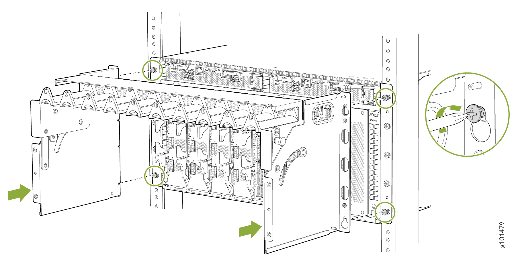
ケーブルマネージャーの両側にあるバネ仕掛けのピンを引き出し、トレイを下に移動してRCBにアクセスします。 図4をご覧ください。
図4:トレイを移動してRCB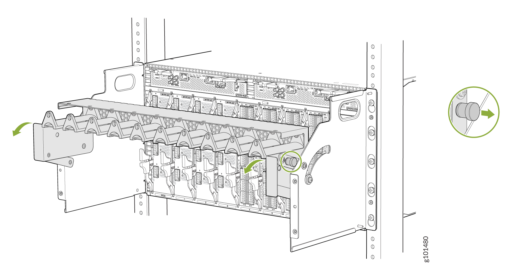 にアクセスする
にアクセスする
FPCにアクセスするには、トレイを移動する必要があります。 図5をご覧ください。
図5:トレイを移動してFPC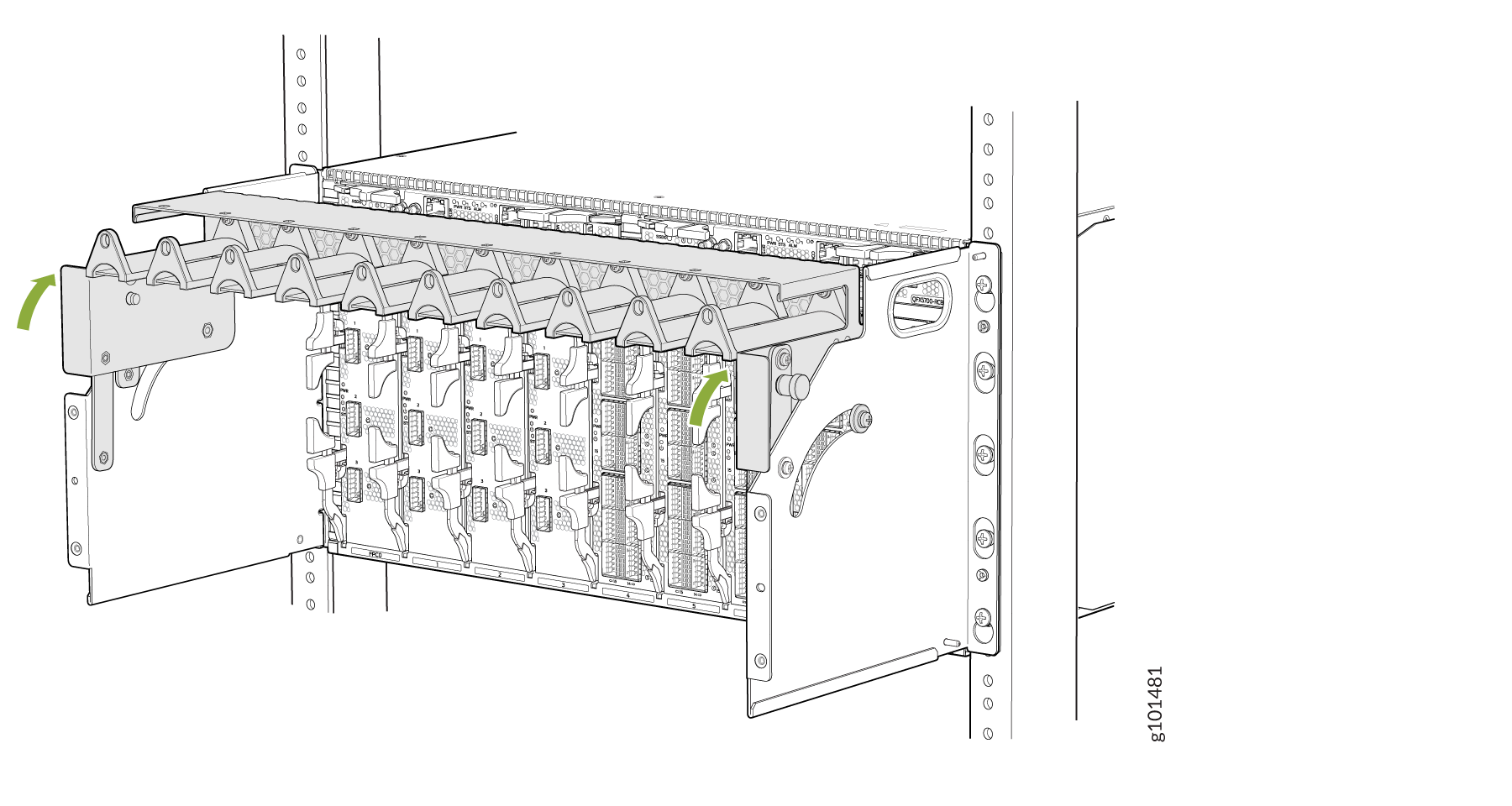 にアクセスする
にアクセスする
次に、ケーブルマネージャーをロックします。 図6をご覧ください。
図6:ケーブルマネージャーのロック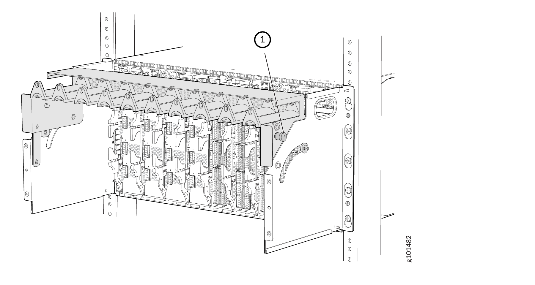
ケーブルマネージャーを介してケーブルを配線する方法を理解するには、 図7 と 図8 を参照してください。
図7:ケーブルマネージャー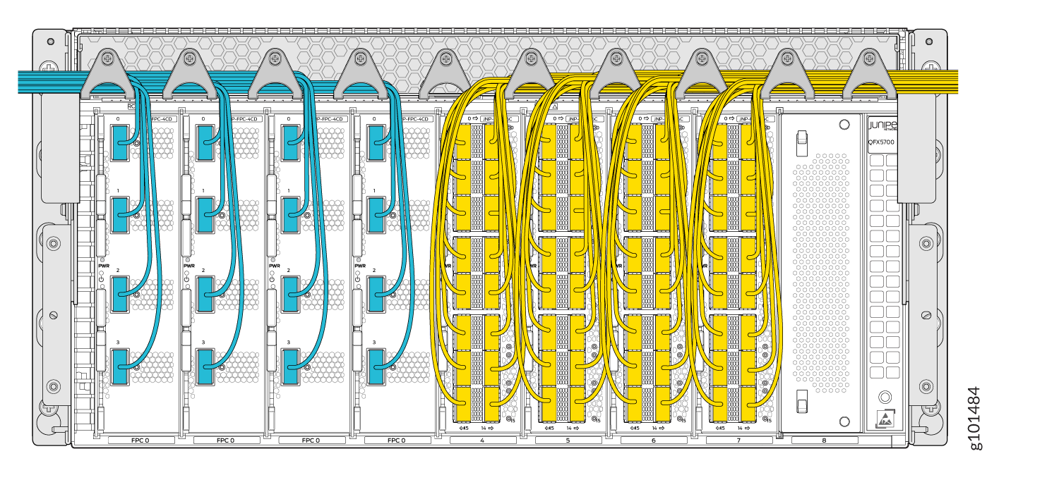 を介してケーブルを配線する
を介してケーブルを配線する
ケーブルマネージャーを使用してケーブルをルーター接続したら、ケーブルマネージャーカバーを組み立てます。
図8:ケーブルマネージャーカバー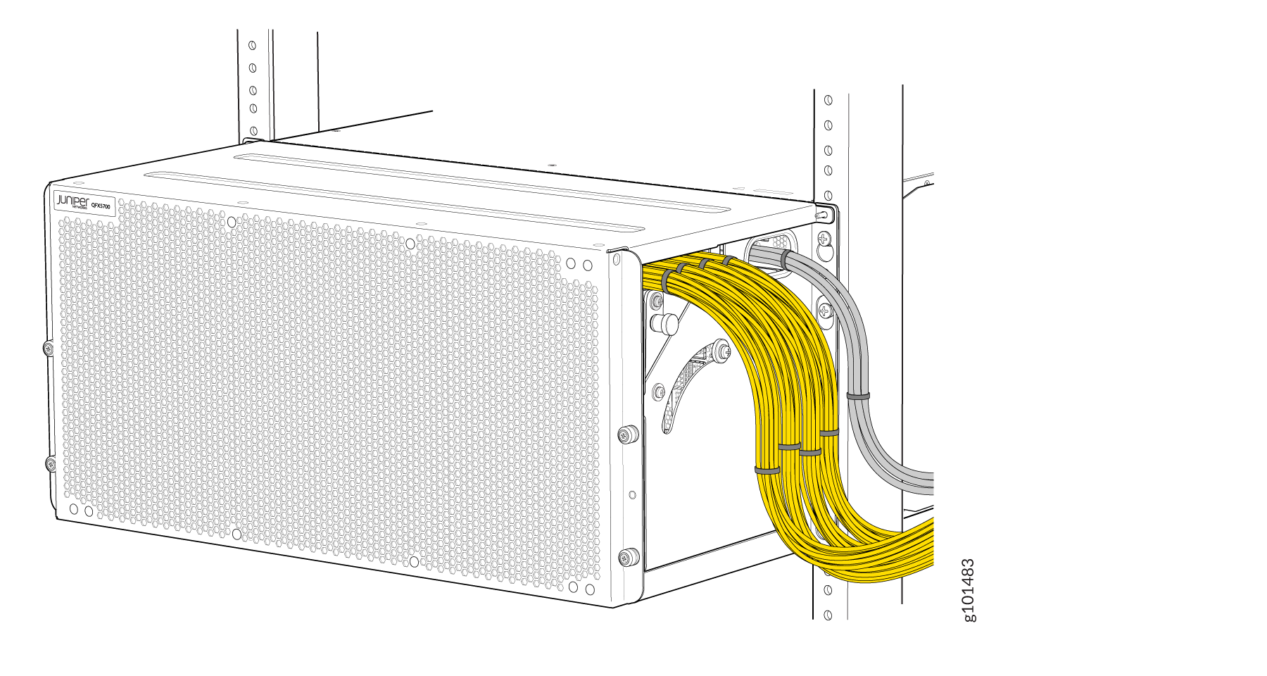 の組み立て
の組み立て
の組み立て
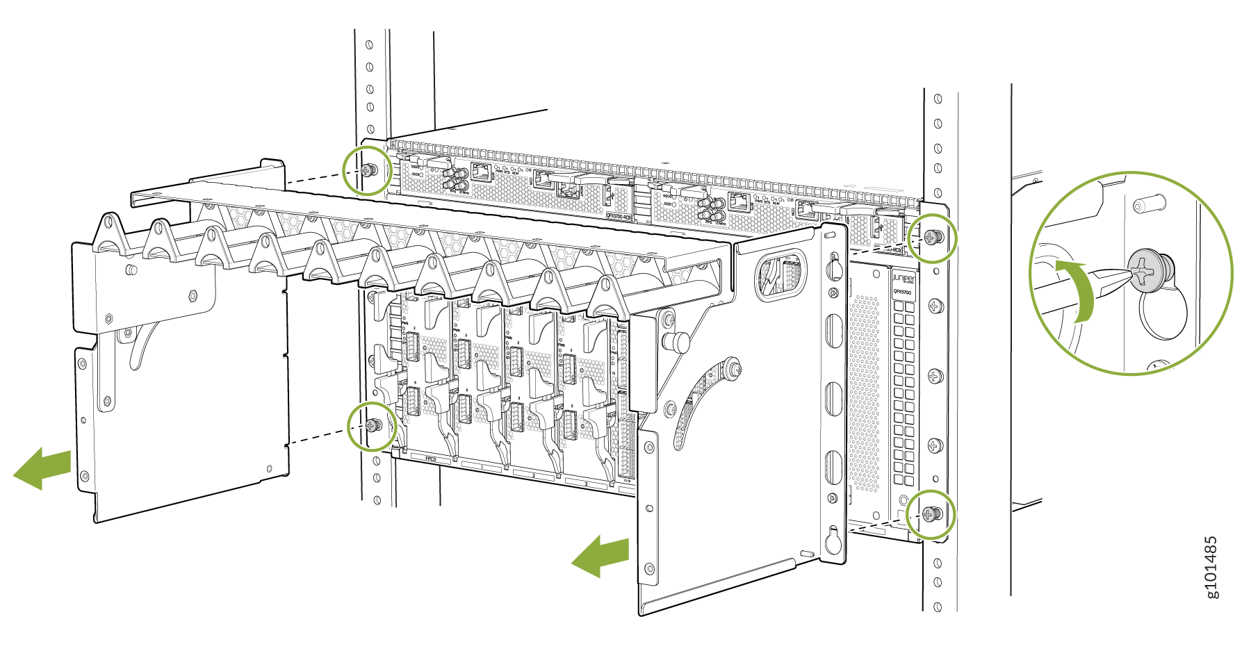
図 9 は、ケーブル マネージャーを取り外す方法を示しています。
図9:ケーブルマネージャーの取り外し