ME-X6を取り付ける
このトピックでは、デバイスを 2 ポストまたは 4 ポスト ラックに取り付ける手順について説明します。
取り付けプロセスは、両方のME-X6バリエーションで同じです。図はME-X6バリアント1を示しています。
ME-X6 に同梱されているラック取り付けキットには、以下の部品が含まれています。
-
2つのレール取り付けアセンブリ
-
Lブラケット x 4
-
取り付けブラケットをデバイスに取り付けるための2本のネジ
-
取り付けレールアセンブリをラックポストに取り付けるための4本のネジ
-
4つの円錐形ワッシャー
-
Lブラケットを取り付けレールアセンブリに取り付けるためのネジ8本
-
L ブラケットをラック支柱に取り付けるためのネジ 8 本
-
8つのケージナット
-
8つの角ワッシャー
-
ケーブル管理用タイ 2 本
図1:ラック取り付けキットのコンポーネント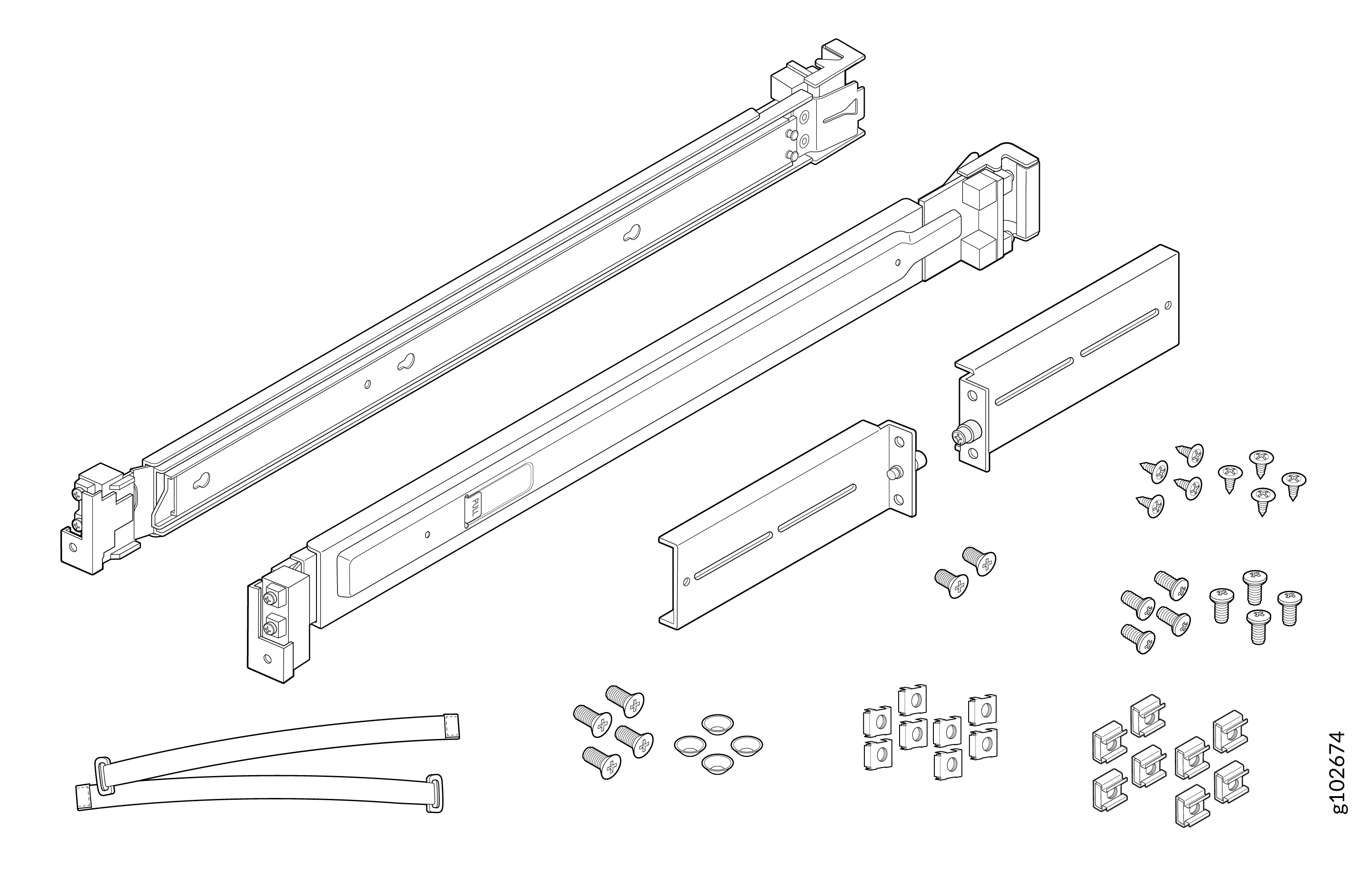
デバイスを4ポストラックに取り付けます
デバイスを4ポストラックに取り付けるには:
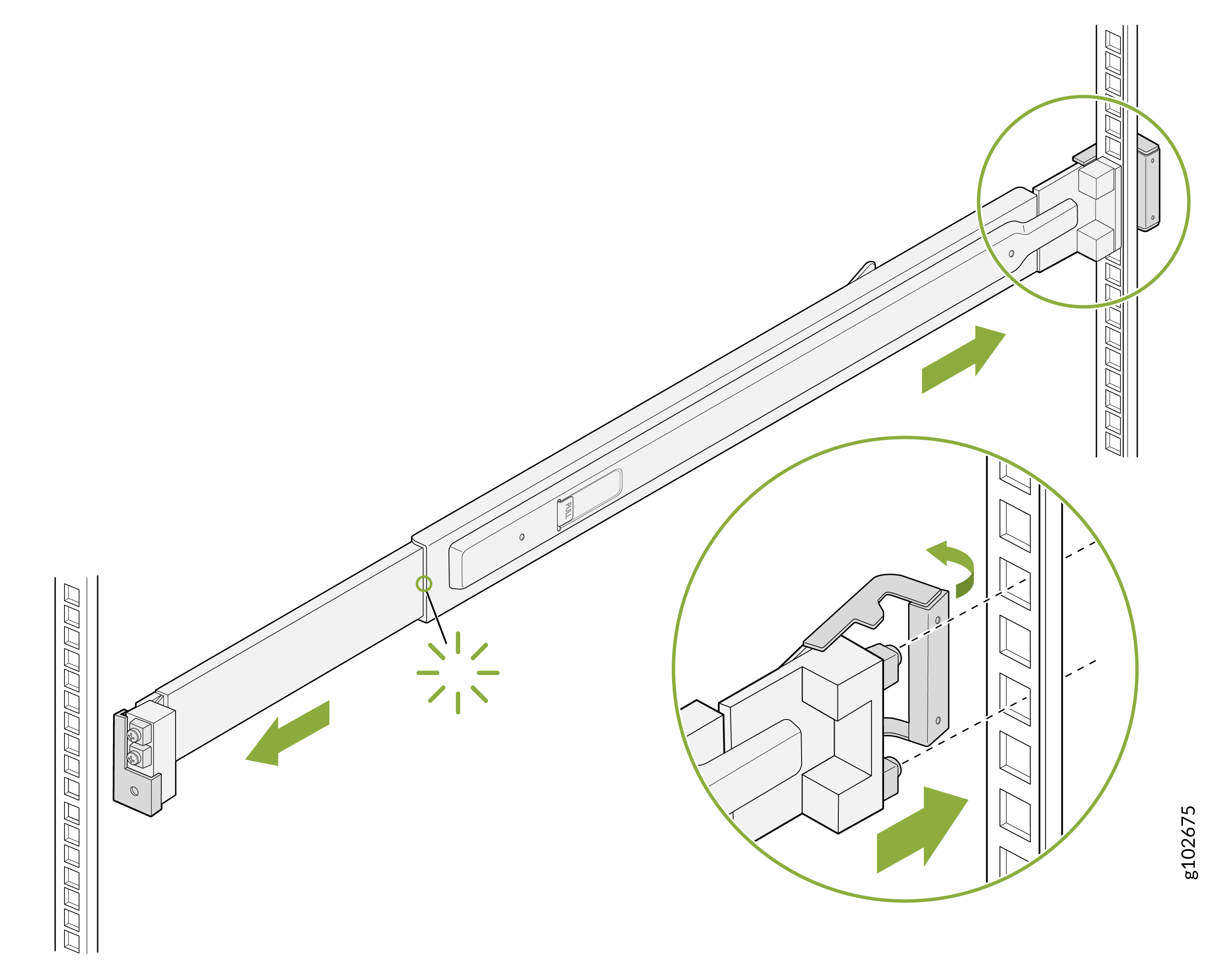
- 取り付けレール アセンブリの背面レールにあるラッチを開きます。リアレールのガイドブロックをリアポストの穴に合わせます。ガイド・ブロックがリア・ポストの穴にスライドするように、リア・レールをラックの背面に向かって押します。背面ラッチを所定の位置にロックします。
図2:リアレール
 の取り付け
の取り付け
- 取り付けレール アセンブリの前面レールにあるラッチを開きます。フロントレールのガイドブロックをフロントポストの穴に合わせます。ガイド・ブロックが前面支柱の穴にスライドするように、前面レールをラックの前面に向かって引っ張ります。
図3:フロントレール
 の取り付け
の取り付け
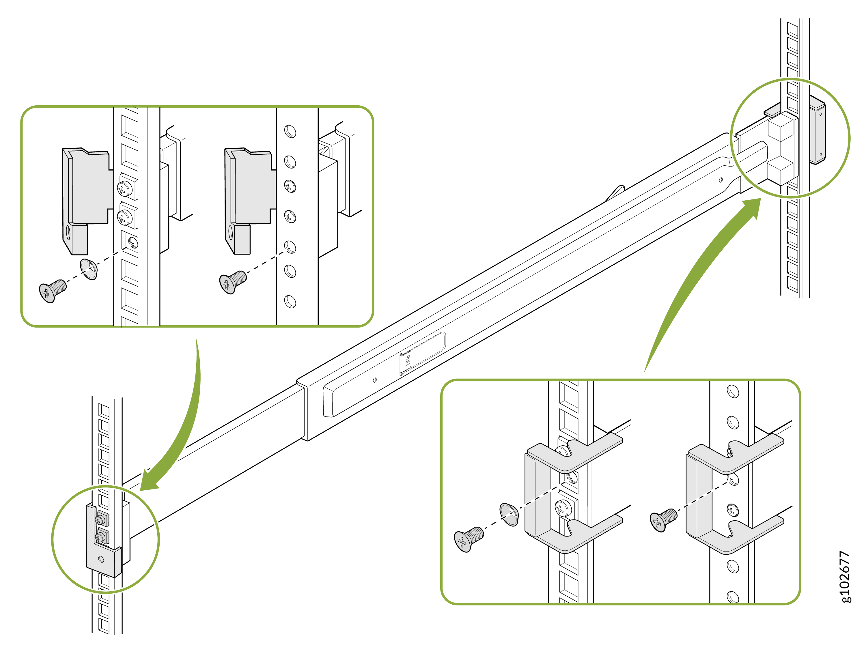
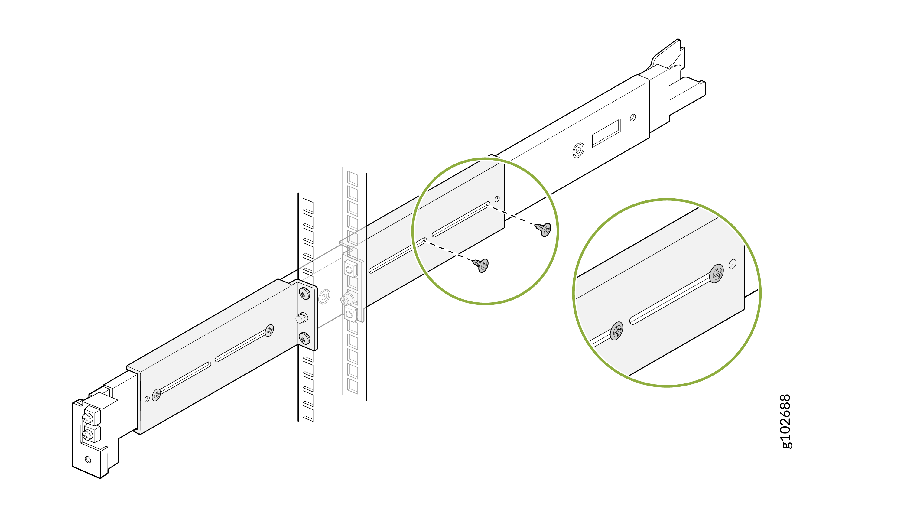
- 付属のネジを使用して、取り付けレールをラック支柱に固定します。前面ラッチを所定の位置にロックします。
四角い穴のあるラックの場合は、円錐形のワッシャーを使用してください。図4:取り付けレールの固定
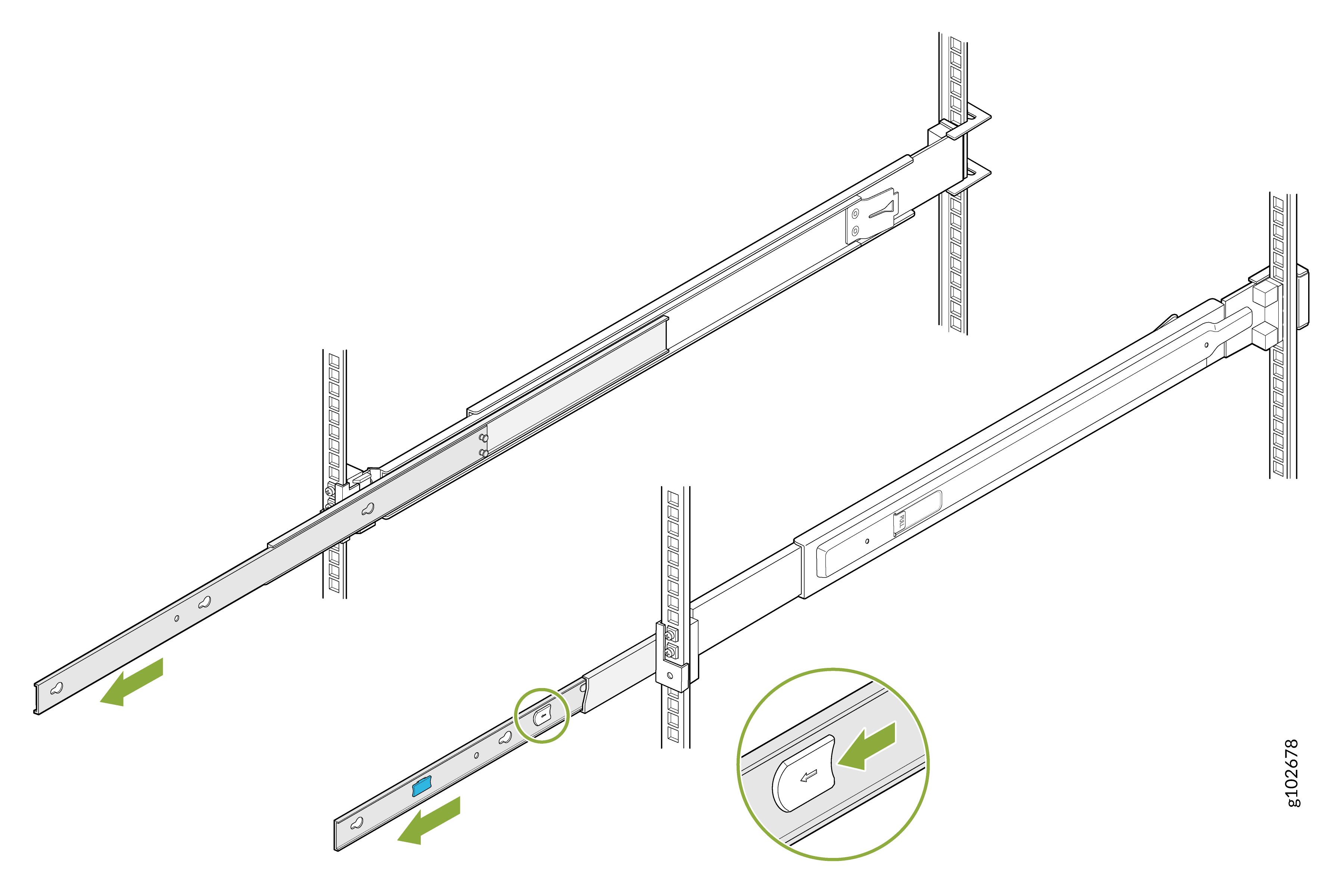
- 取り付けレールを完全に引き出します。各レールのラッチを押し、引っ張って最も内側の取り付けブラケットを取り外します。
図5:取り付けブラケットの取り外し
- 各取り付けブラケットの穴をデバイス側面の肩付きネジに合わせます。取り付けブラケットをデバイスの背面に向かってスライドさせて取り付けます。付属のネジを使用して、取り付けブラケットをデバイスに固定します。
図6:取り付け用ブラケットをデバイス
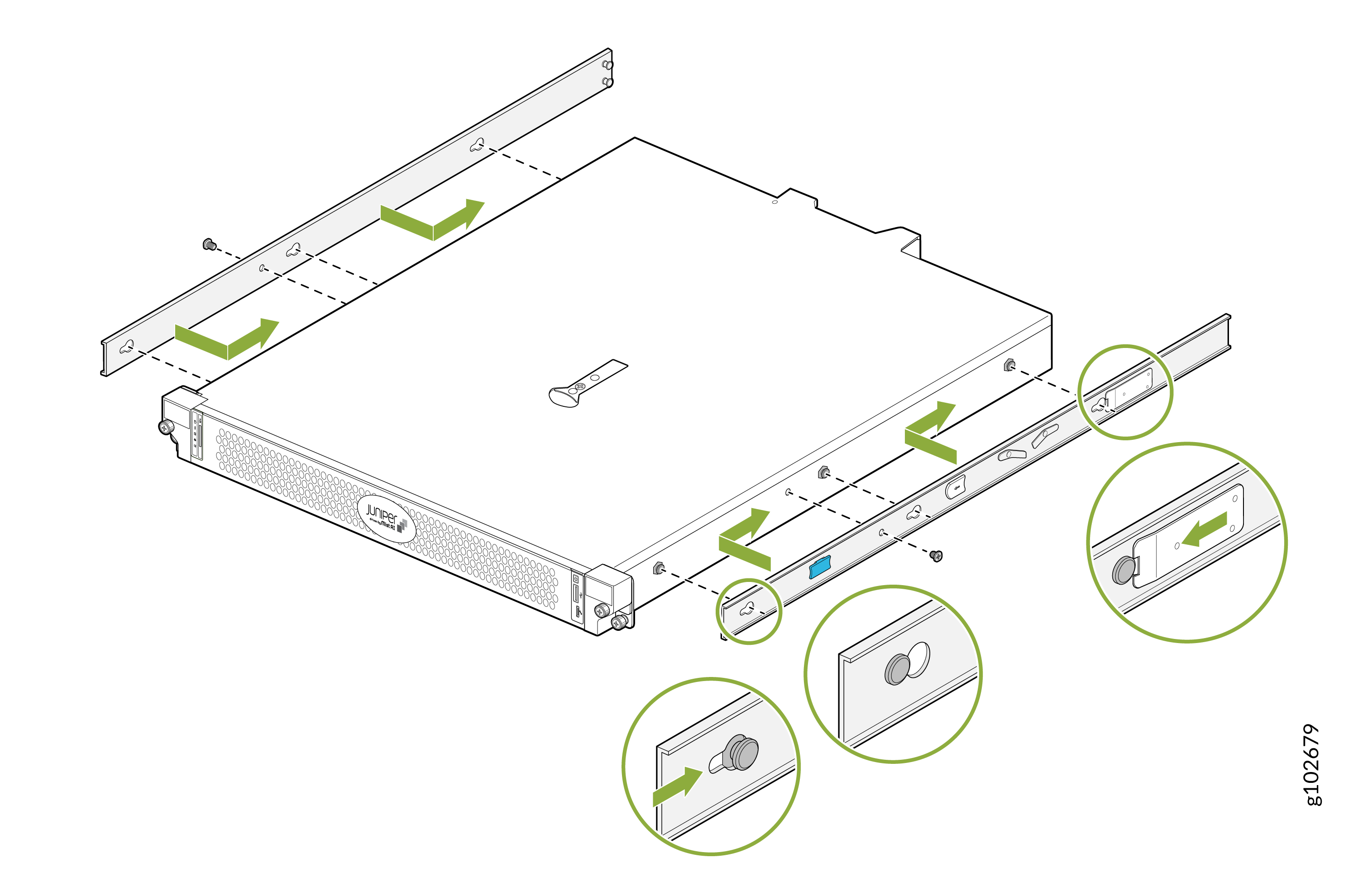 に取り付ける
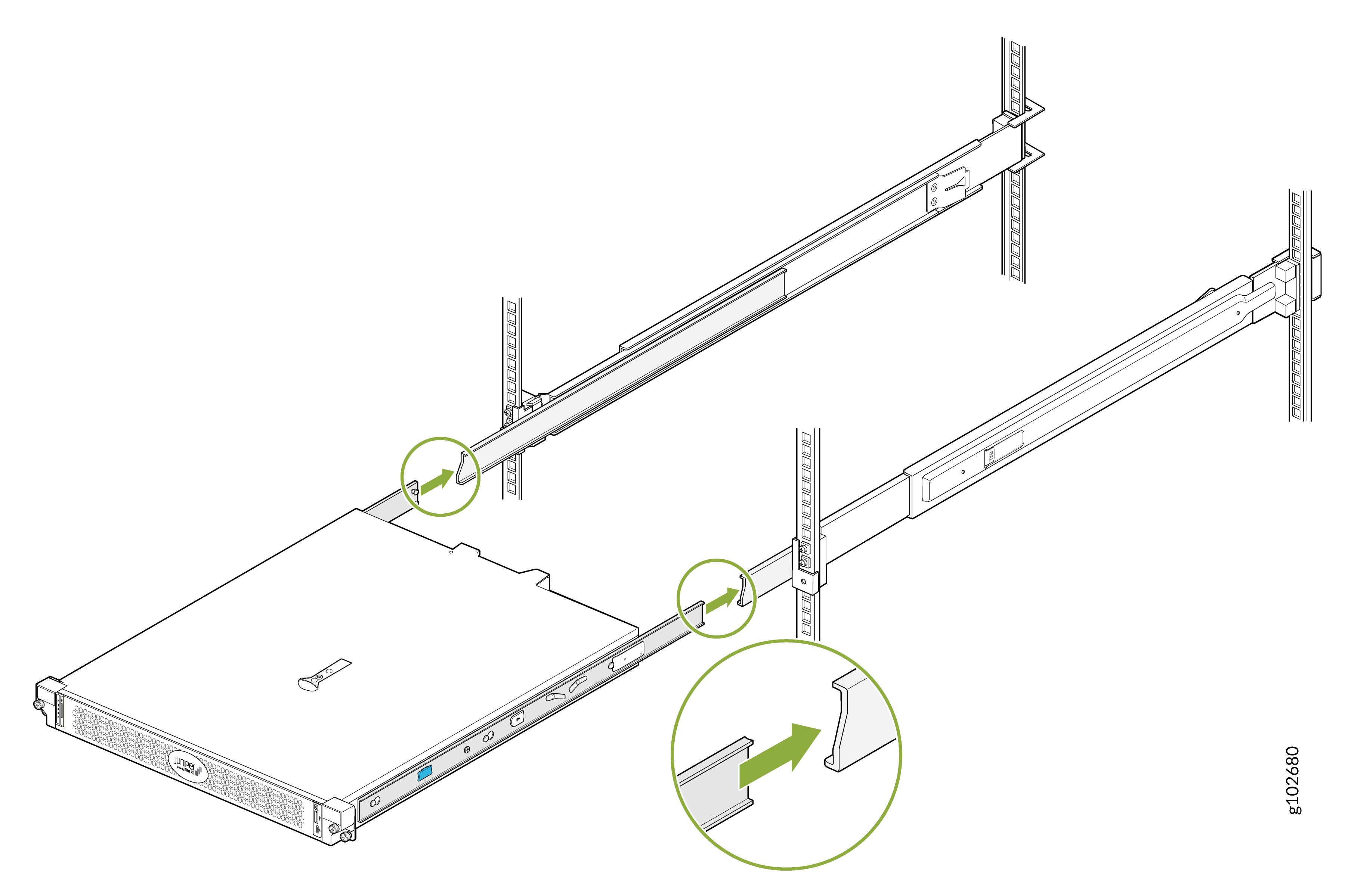
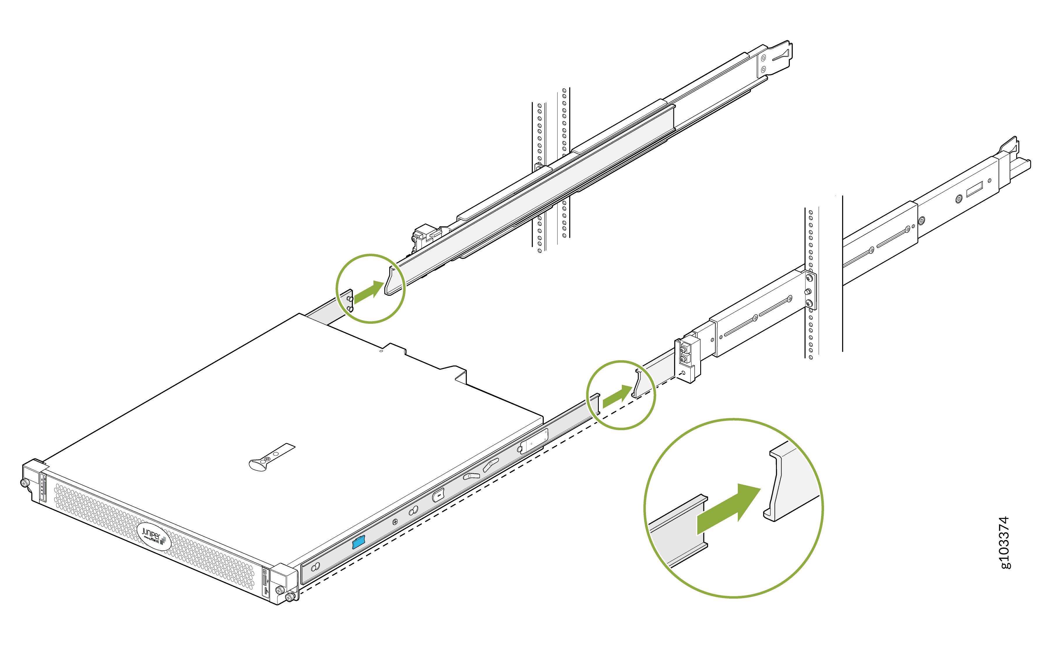
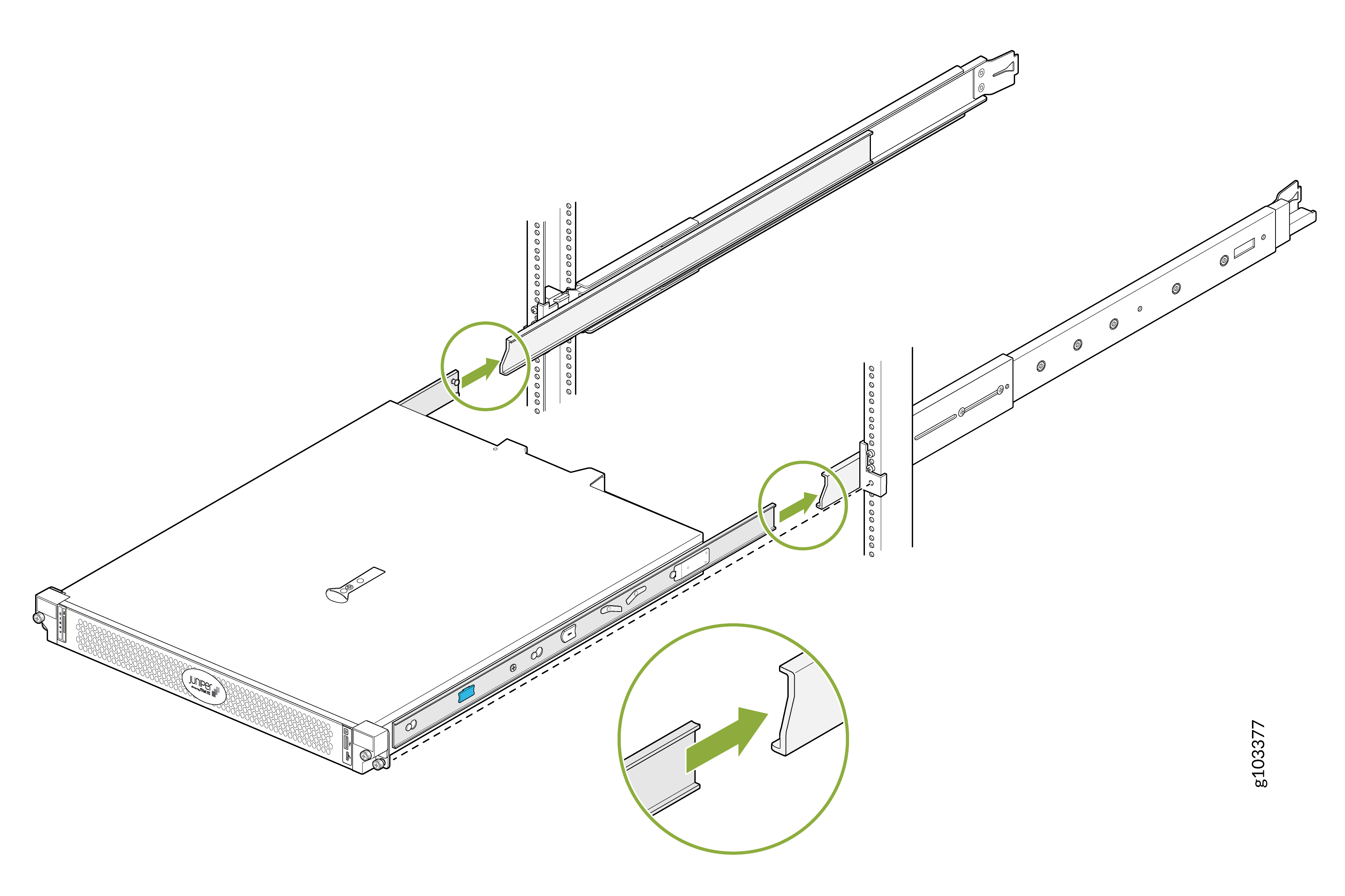
- デバイスを持ち上げ、取り付けブラケットが取り付けレールに位置合わせされるように配置します。デバイスを取り付けレールのチャネルにスライドさせます。
図7:デバイスを取り付けレールにスライドさせます
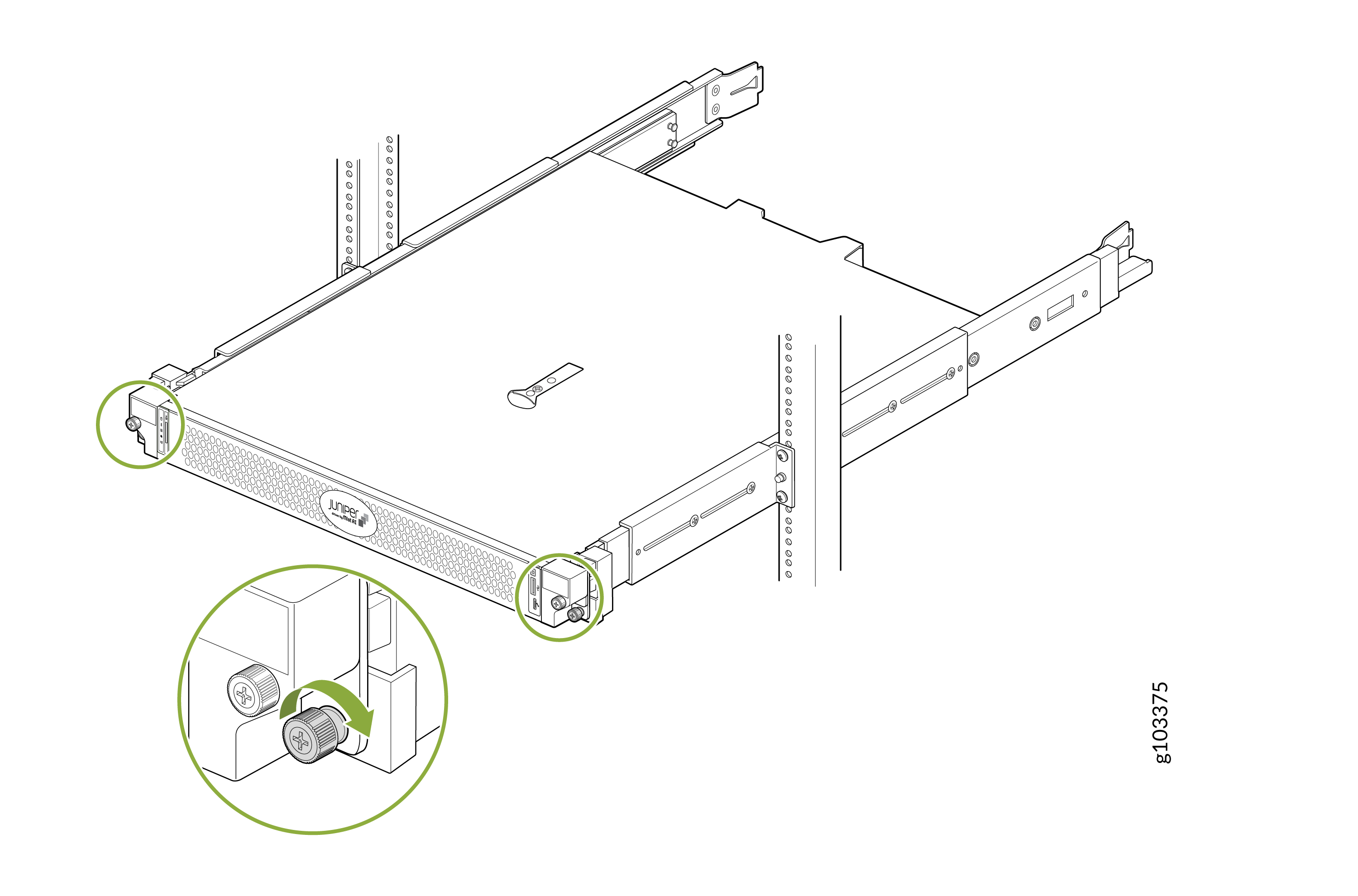
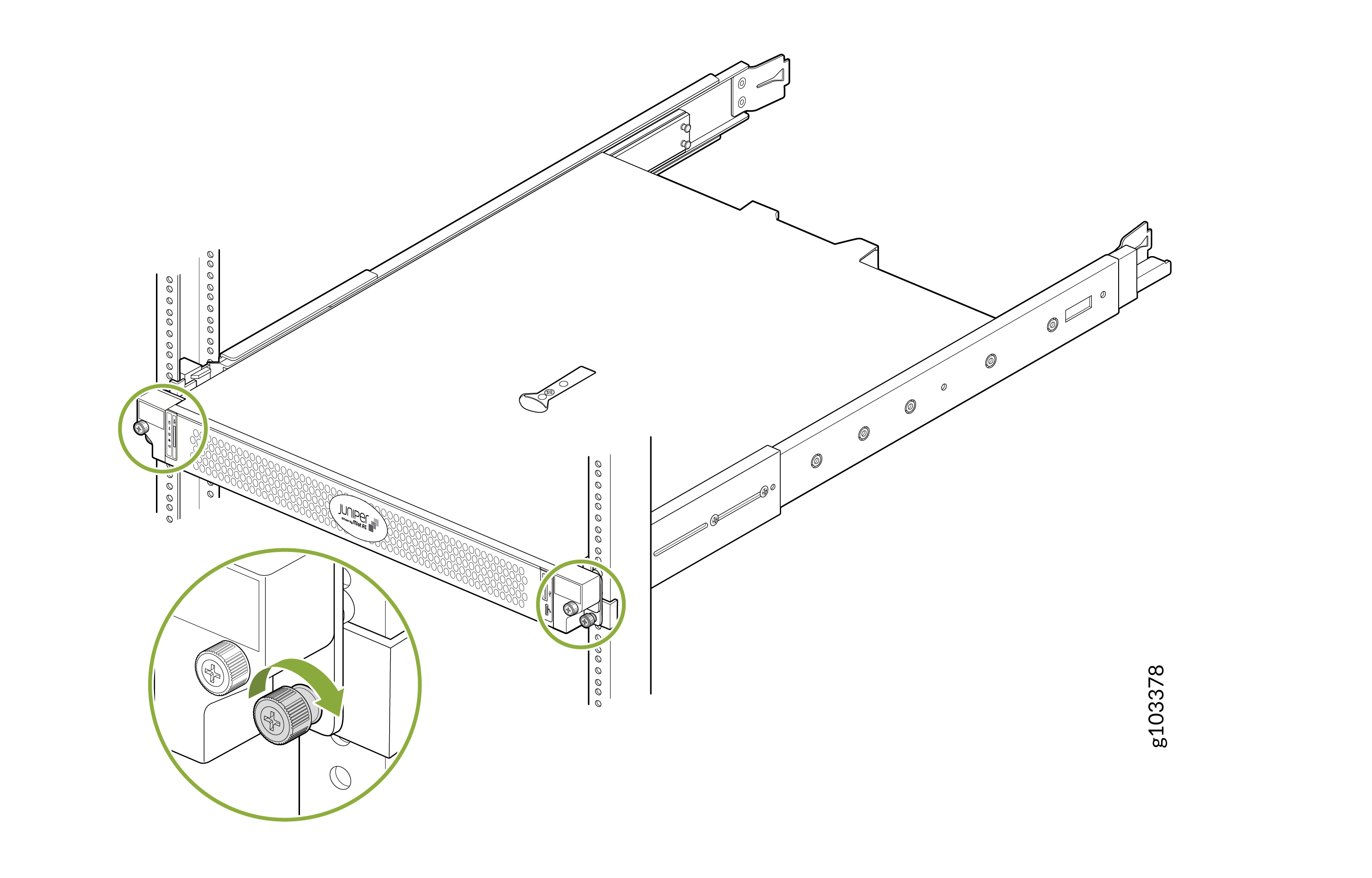
- デバイスの前面フランジのネジを締めて、ラックに固定します。
図8:デバイスの
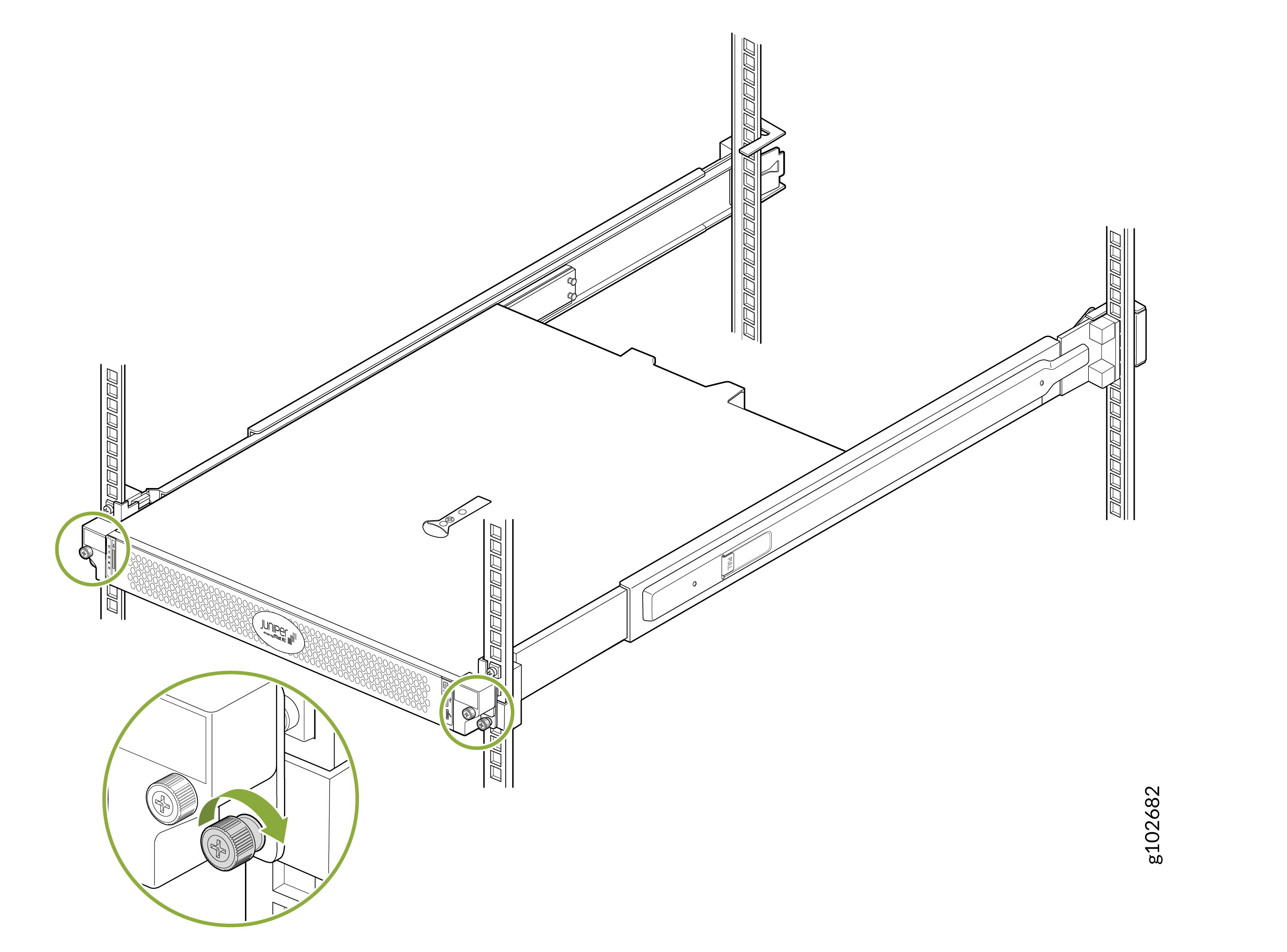 を固定する
を固定する
デバイスを 2 ポスト ラック(センター マウント)に取り付けます。
デバイスを 2 ポスト ラックの中央に取り付けるには、次の手順に従います。
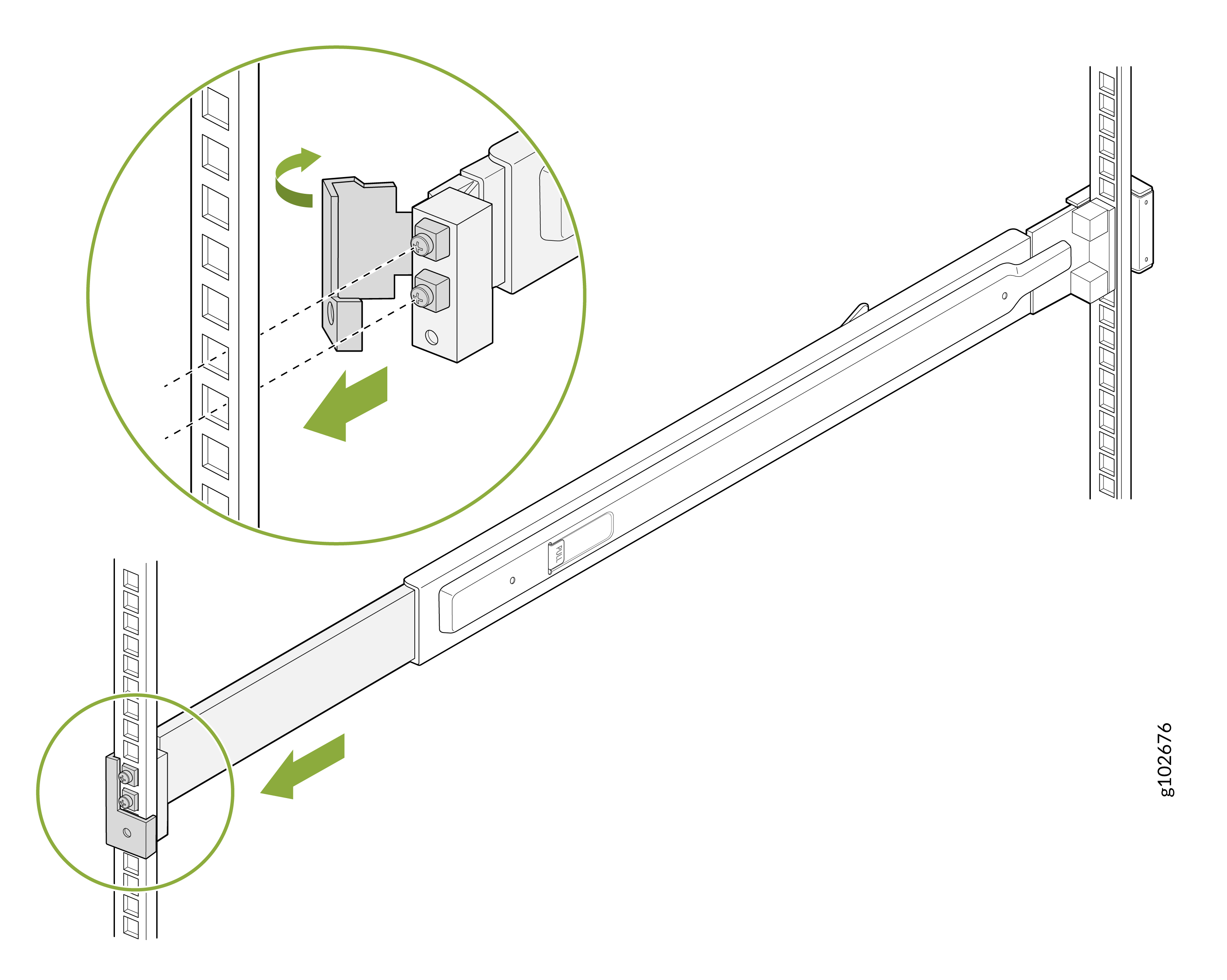
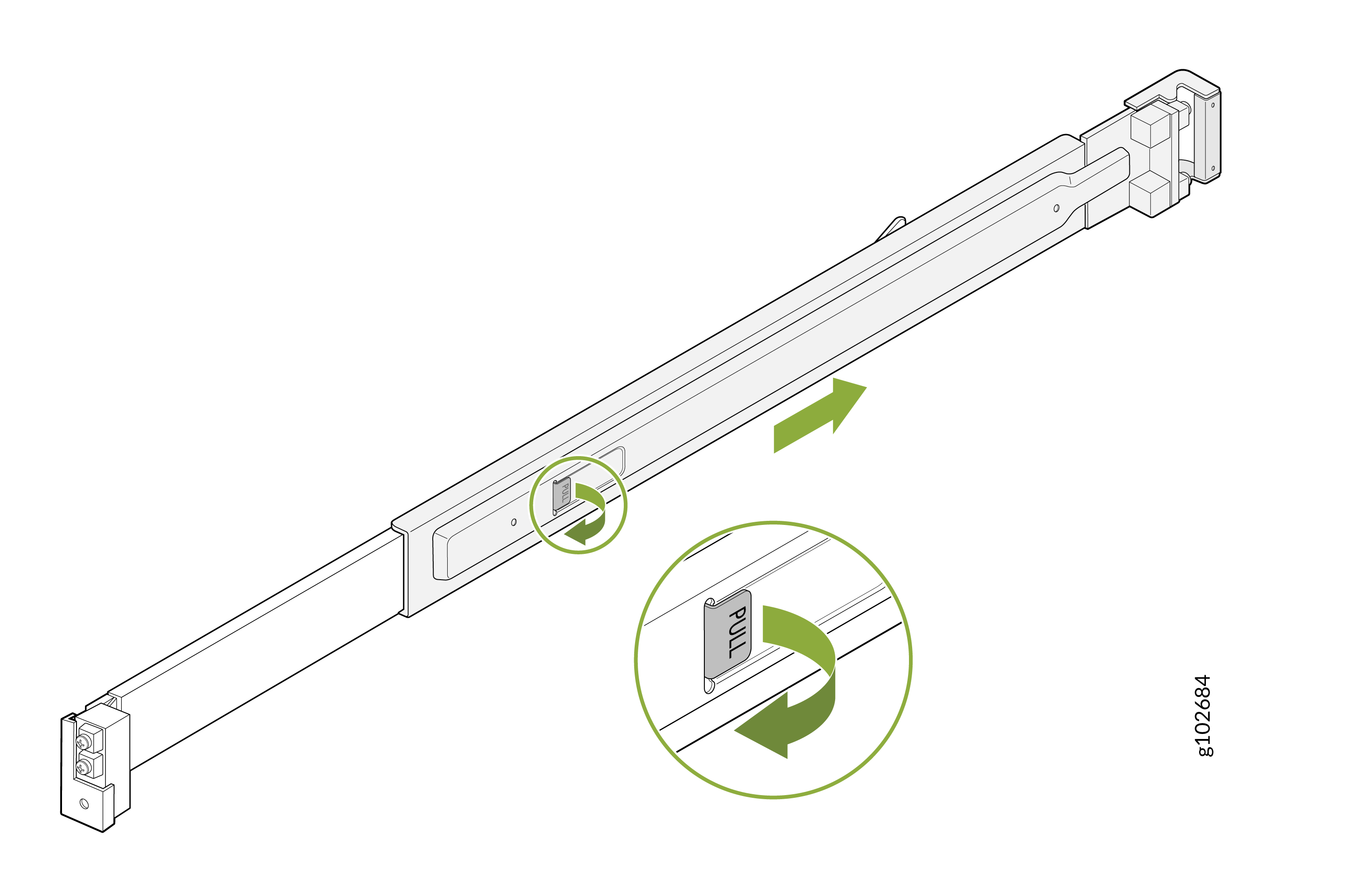
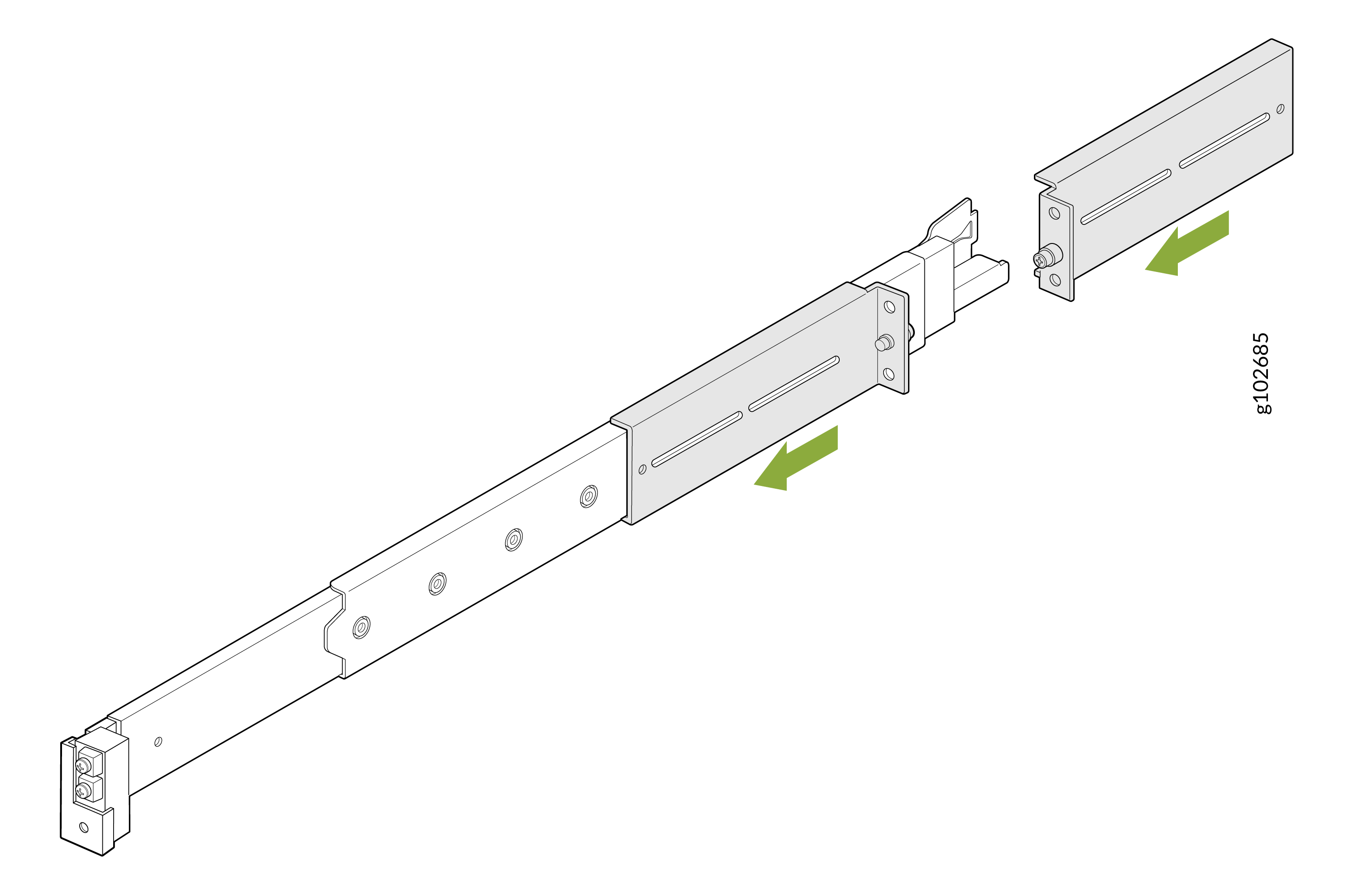
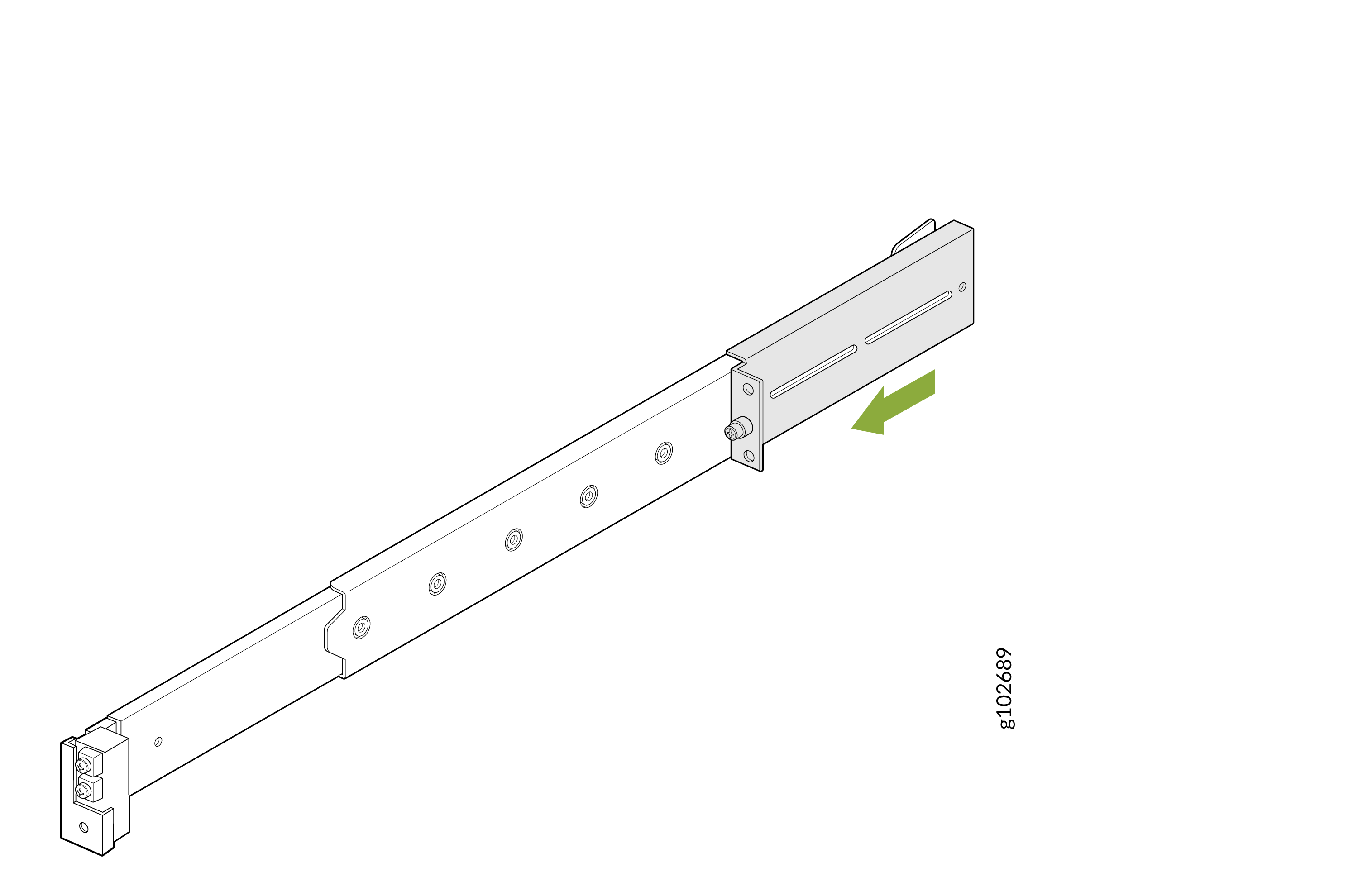
- 取り付けレールアセンブリのラッチを引っ張り、背面レールをスライドさせて引き出します。
図9:リアレールの取り外し
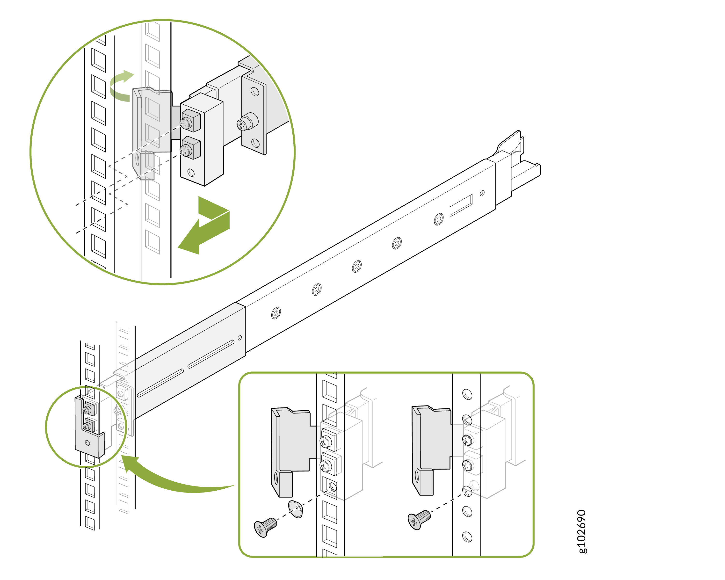
- 2 つの L ブラケットを取り付けレール アセンブリの前面レールにスライドさせます。Lブラケットのフランジが向かい合っていることを確認してください。
図10:Lブラケット
 の取り付け
の取り付け
- 付属のネジを使用して、前面Lブラケットを取り付けレールアセンブリに固定します。
図11:前面Lブラケット
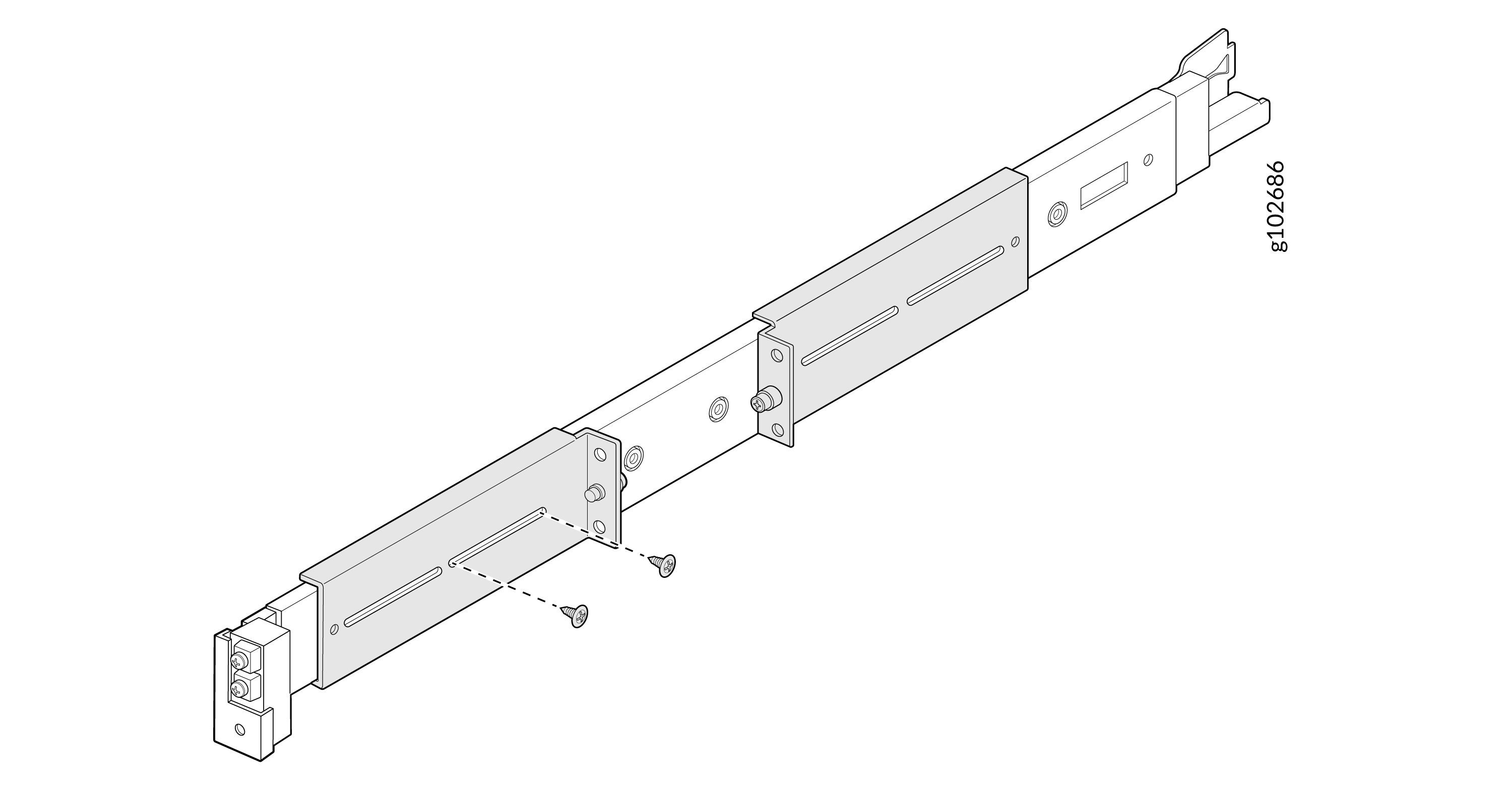 の固定
の固定
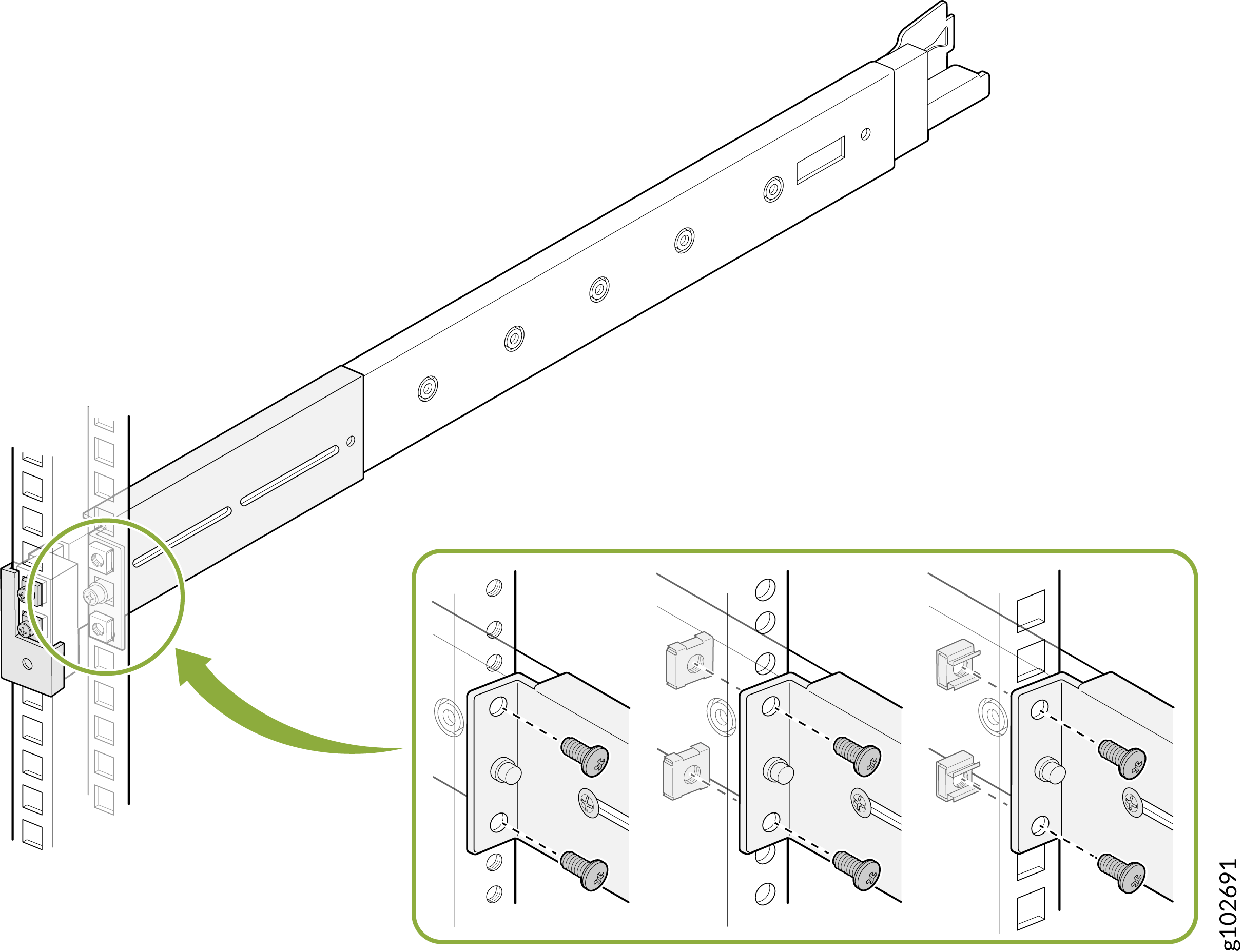
- 付属のネジとワッシャーを使用して、前面と背面のLブラケットをラックポストに取り付けます。
図12:ラック
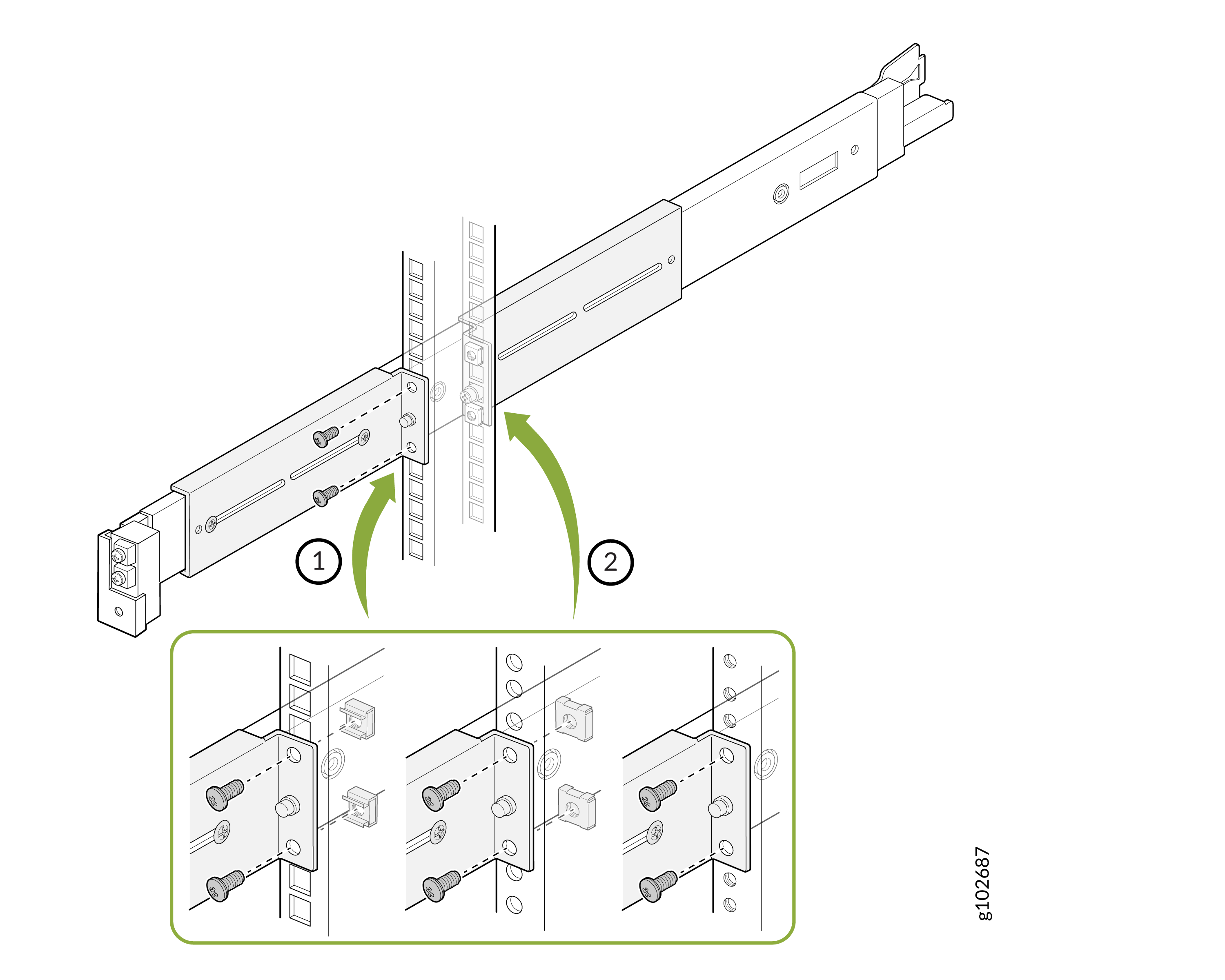 へのLブラケットの取り付け
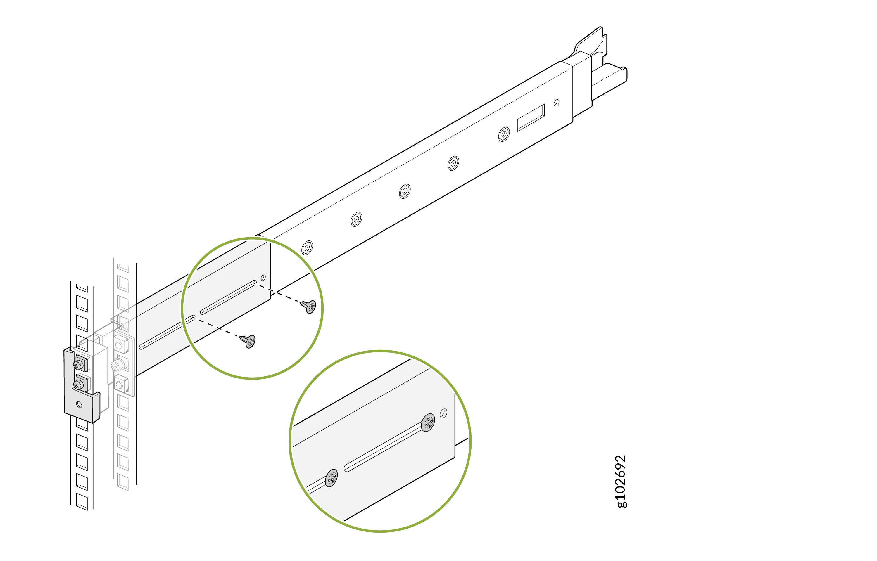
- 付属のネジを使用して、背面Lブラケットを取り付けレールアセンブリに固定します。
図13:背面Lブラケット
 の固定
の固定
- 取り付けレールを完全に引き出します。各レールのラッチを押し、引っ張って最も内側の取り付けブラケットを取り外します。
図14:取り付け用ブラケットの取り外し
- 各取り付けブラケットの穴をデバイス側面の肩付きネジに合わせます。取り付けブラケットをデバイスの背面に向かってスライドさせて取り付けます。付属のネジを使用して、取り付けブラケットをデバイスに固定します。
図15:取り付けブラケットをデバイスに取り付ける
- デバイスを持ち上げ、取り付けブラケットが取り付けレールに位置合わせされるように配置します。デバイスを取り付けレールのチャネルにスライドさせます。
図16:デバイスを取り付けレールにスライドさせます
- デバイスの前面フランジのネジを締めて、ラックに固定します。
図17:デバイスの
 を固定する
を固定する
デバイスを 2 ポスト ラックに取り付けます(フラッシュ マウント)
デバイスを 2 ポスト ラックにフラッシュ マウントするには、次の手順に従います。
- 取り付けレールアセンブリのラッチを引っ張り、背面レールをスライドさせて引き出します。
図18:リアレールの取り外し
- フランジがラックの前面を向くように、取り付けレールアセンブリのLブラケットをスライドさせます。
図19:Lブラケット
 の取り付け
の取り付け
- 取り付けレール アセンブリの前面レールにあるラッチを開きます。フロントレールのガイドブロックをフロントポストの穴に合わせます。ガイド・ブロックが前面支柱の穴に差し込まれるように、前面レールをラックの前面に向かって引きます。付属のネジと円錐ワッシャーを使用して、フロントレールを固定します。ラッチをロックします。
図20:フロントレール
 の取り付け
の取り付け
- 付属のネジとワッシャーを使用して、L ブラケットをラック支柱に固定します。
図21:Lブラケットをラックポスト
 に取り付けます
- 付属のネジを使用して、L ブラケットを取り付けレール アセンブリに固定します。
図22:Lブラケットを取り付けレールアセンブリ
 に取り付けます
- 取り付けレールを完全に引き出します。各レールのラッチを押し、引っ張って最も内側の取り付けブラケットを取り外します。
図23:取り付け用ブラケットの取り外し
- 各取り付けブラケットの穴をデバイス側面の肩付きネジに合わせます。取り付けブラケットをデバイスの背面に向かってスライドさせて取り付けます。付属のネジを使用して、取り付けブラケットをデバイスに固定します。
図24:取り付けブラケットをデバイスに取り付けます
- デバイスを持ち上げ、取り付けブラケットが取り付けレールに位置合わせされるように配置します。デバイスを取り付けレールのチャネルにスライドさせます。
図25:デバイスを取り付けレールにスライドさせます
- デバイスの前面フランジのネジを締めて、ラックに固定します。
図26:デバイスの
 を固定する
を固定する