Exemple : configuration VPLS (signalisation BGP)
 de topologie VPLS
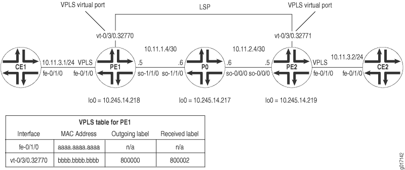
Sur la figure 1, une topologie VPLS simple est activée entre les routeurs PE1 et PE2. Les routeurs CE1 et CE2 utilisent des interfaces Ethernet pour connecter le VLAN 600 à leur routeur PE local. Les routeurs PE PE1 et PE2 sont connectés les uns aux autres par des LSP sur un réseau dorsal de fournisseur de services exécutant MPLS, BGP, RSVP et OSPF.
Dans une instance de routage VPLS nommée green, PE1 dispose d’une interface fe-0/1/0 locale et d’un port virtuel de vt-0/3/0.32770 (le port virtuel est créé dynamiquement sur le PIC des services de tunnel lorsque VPLS est configuré). PE2 dispose d’une interface fe-0/1/0 locale et d’un port virtuel dans vt-0/3/0.32771 la même green instance. En conséquence, les routeurs CE1 et CE2 envoient le trafic Ethernet entre eux comme s’ils étaient physiquement connectés sur un LAN.
Sur le routeur CE1, le seul élément à configurer est l’interface Fast Ethernet qui se connecte au PE1. N’oubliez pas d’écrire l’identifiant VLAN et l’adresse IP pour pouvoir les faire correspondre ultérieurement sur le CE2.
Routeur CE1
[edit]
interfaces {
    fe-0/1/0 {
        vlan-tagging; # Configure VLAN tagging for VLAN VPLS or extended VLAN VPLS.
        unit 0 {
            vlan-id 600; # The Ethernet interface on CE2 must use the same VLAN ID.
            family inet {
                address 10.11.3.1/24; # The interface on CE2 must use the same prefix.
            }
        }
    }
}
Si le routeur PE1 est un équipement MX Series, vous devez configurer une interface de service de tunnel.
Pour créer des interfaces tunnel sur un routeur MX Series, incluez l’instruction tunnel-services au niveau de la hiérarchie [edit chassis fpc slot-number pic number]. Pour configurer la bande passante d’une interface tunnel, incluez l’instruction bandwidth au niveau de la hiérarchie [edit chassis fpc slot-number pic number tunnel services].
L’exemple suivant illustre une interface tunnel avec 1 Gbit/s de bande passante configurée sur le PFE 3 du DPC installé dans l’emplacement 0 d’un routeur MX Series :
[edit chassis]
fpc 0 {
    pic 3 {
        tunnel services {
            bandwidth 1g;
        }
    }
}
Sur le routeur PE1, préparez le routeur pour VPLS en configurant BGP, MPLS, OSPF et RSVP. (Ces protocoles sont à la base de la plupart des applications VPN de couche 2, y compris VPLS.) Incluez l’énoncé signaling au niveau de la [edit protocols bgp group group-name family l2vpn] hiérarchie, car VPLS utilise la même infrastructure pour BGP interne que les VPN de couche 2.
Dans Junos OS version 7.3 et versions ultérieures, l’instruction signaling remplace l’instruction unicast au niveau de la [edit protocols bgp group group-name family l2vpn] hiérarchie. Vous devez utiliser l’instruction signaling si vous souhaitez configurer simultanément les domaines VPLS et les VPN de couche 2.
Ensuite, configurez le balisage VLAN sur l’interface Fast Ethernet connectée au routeur CE1. Incluez l’encapsulation VLAN VPLS au niveau de l’interface physique et logique. Assurez-vous d’utiliser le même ID VLAN pour toutes les interfaces Ethernet qui font partie d’une seule instance VPLS. Enfin, ajoutez l’interface Fast Ethernet à une instance de routage VPLS et spécifiez la plage de sites, le numéro d’IDENTIFICATION du site et le nom du site.
Routeur PE1
[edit]
interfaces {
                     fe-0/1/0 {
                         vlan-tagging;# Configure VLAN tagging for VLAN VPLS or extended VLAN VPLS.
                         encapsulation vlan-vpls; # Configure VPLS encapsulation on both the
        unit 0 { # physical interface and the logical interface.
                               encapsulation vlan-vpls;
                               vlan-id 600;# The VLAN ID is the same one used by the CE routers.
        }
    }
    so-1/1/0 {
        unit 0 {
            family inet {
                address 10.11.1.5/30;
            }
            family mpls;
        }
    }
    lo0 {
        unit 0 {
            family inet {
                address 10.245.14.218/32;
            }
        }
    }
}
routing-options {
    autonomous-system 69;
    forwarding-table {
        export exp-to-fwd; # Apply a policy that selects an LSP for the VPLS instance.
    }
}
protocols {
                     rsvp {
        interface all {
            aggregate;
        }
    }
                     mpls {
                           label-switched-path pe1-to-pe2 { # Configure an LSP to reach other VPLS PEs.
            to 10.245.14.219;
        }
        interface all;
    }
    bgp {
        group vpls-pe {
            type internal;
            local-address 10.245.14.218;
            family l2vpn { # VPLS uses the same infrastructure as Layer 2 VPNs
                signaling; # for internal BGP.
            }
            neighbor 10.245.14.217;
            neighbor 10.245.14.219;
        }
    }
    ospf {
        traffic-engineering;
        area 0.0.0.0 {
            interface so-1/1/0.0 {
                metric 11;
            }
            interface lo0.0 {
                passive;
            }
        }
    }
}
policy-options {
    policy-statement exp-to-fwd {
        term a {
            from community grn-com; # Matches the community in the VPLS instance.
            then {
                install-nexthop lsp pe1-to-pe2; # If there are multiple LSPs that exist
                accept; # between VPLS PE routers, this statement sends VPLS traffic
            } # over a specific LSP.
        }
    }
    community grn-com members target:11111:1; # Adds the instance to a BGP
} # community.
routing-instances {
    green {
        instance-type vpls; # Configure a VPLS routing instance.
        interface fe-0/1/0.0;
        route-distinguisher 10.245.14.218:1;
        vrf-target target:11111:1; # This value is important to the BGP community.
        protocols {
            vpls { # Configure a VPLS site range, site name, and site identifier.
                site-range 10;
                site greenPE1 {
                    site-identifier 1;
                }
            }
        }
    }
}
Sur le routeur P0, configurez BGP, MPLS, OSPF et RSVP pour interconnecter PE1 et PE2.
Routeur P0
[edit]
interfaces {
    so-0/0/0 {
        unit 0 {
            family inet {
                address 10.11.2.6/30;
            }
            family mpls;
        }
    }
                     so-1/1/0 {
        unit 0 {
            family inet {
                address 10.11.1.6/30;
            }
            family mpls;
        }
    }
    lo0 {
        unit 0 {
            family inet {
                address 10.245.14.217/32;
            }
        }
    }
}
routing-options {
    autonomous-system 69;
}
protocols {
                     rsvp {
        interface all {
            aggregate;
        }
    }
                     mpls {
        interface all;
    }
    bgp {
        group vpls-pe {
            type internal;
            local-address 10.245.14.217;
            family l2vpn { # VPLS uses the same infrastructure as Layer 2 VPNs
                signaling; # for internal BGP.
            }
            neighbor 10.245.14.218;
            neighbor 10.245.14.219;
        }
    }
    ospf {
        traffic-engineering;
        area 0.0.0.0 {
            interface so-1/1/0.0 {
                metric 11;
            }
            interface so-0/0/0.0 {
                metric 15;
            }
            interface lo0.0 {
                passive;
            }
        }
    }
}
Si le routeur PE2 est un équipement MX Series, vous devez configurer des interfaces de service de tunnel.
Pour créer des interfaces tunnel sur un routeur MX Series, incluez l’instruction tunnel-services au niveau de la hiérarchie [edit chassis fpc slot-number pic number]. Pour configurer la bande passante d’une interface tunnel, incluez l’instruction bandwidth au niveau de la hiérarchie [edit chassis fpc slot-number pic number].
L’exemple suivant illustre une interface tunnel avec 1 Gbit/s de bande passante configurée sur le PFE 3 du DPC installé dans l’emplacement 0 d’un routeur MX Series :
[edit chassis]
fpc 0 {
    pic 3 {
        tunnel services {
            bandwidth 1g;
        }
    }
}
Sur le routeur PE2, configurez BGP, MPLS, OSPF et RSVP pour compléter la configuration sur PE1. Ensuite, configurez le balisage VLAN sur l’interface Fast Ethernet connectée au routeur CE2. Incluez l’encapsulation VLAN VPLS au niveau de l’interface physique et logique. Assurez-vous d’utiliser le même ID VLAN pour toutes les interfaces Ethernet qui font partie d’une seule instance VPLS. Enfin, ajoutez l’interface Fast Ethernet à une instance de routage VPLS et spécifiez la plage de sites, le numéro d’IDENTIFICATION du site et le nom du site.
Routeur PE2
[edit]
interfaces {
    fe-0/1/0 {
        vlan-tagging; # Configure VLAN tagging for VLAN VPLS or extended VLAN VPLS.
        encapsulation vlan-vpls; # Configure VPLS encapsulation on both the
        unit 0 { # physical interface and logical interface.
            encapsulation vlan-vpls;
            vlan-id 600;# The VLAN ID is the same one used by the CE routers.
        }
    }
    so-0/0/0 {
        unit 0 {
            family inet {
                address 10.11.2.5/30;
            }
            family mpls;
        }
    }
    lo0 {
        unit 0 {
            family inet {
                address 10.245.14.219/32;
            }
        }
    }
}
routing-options {
    autonomous-system 69;
    forwarding-table {
        export exp-to-fwd; # Apply a policy that selects an LSP for the VPLS instance.
    }
}
protocols {
    rsvp {
        interface all {
            aggregate;
        }
    }
    mpls {
        label-switched-path pe2-to-pe1 { # Configure an LSP to other VPLS PE routers.
            to 10.245.14.218;
        }
        interface all;
    }
    bgp {
        group vpls-pe {
            type internal;
            local-address 10.245.14.219;
            family l2vpn { # VPLS uses the same infrastructure as Layer 2 VPNs
                signaling; # for internal BGP.
            }
            neighbor 10.245.14.217;
            neighbor 10.245.14.218;
        }
    }
    ospf {
        traffic-engineering;
        area 0.0.0.0 {
            interface so-0/0/0.0 {
                metric 15;
            }
            interface lo0.0 {
                passive;
            }
        }
    }
}
policy-options {
    policy-statement exp-to-fwd {
        term a {
            from community grn-com; # Matches the community with the VPLS instance.
            then {
                install-nexthop lsp pe2-to-pe1; # If there are multiple LSPs that exist
                accept; # between VPLS PE routers, this statement sends VPLS traffic
            }  # over a specific LSP.
        }
    }
    community grn-com members target:11111:1; # This adds the instance into a BGP community.
}
routing-instances {
    green {
        instance-type vpls; # Configure a VPLS routing instance.
        interface fe-0/1/0.0;
        route-distinguisher 10.245.14.219:1;
        vrf-target target:11111:1; # This value is important for the BGP community.
        protocols {
            vpls { # Configure a VPLS site range, site name, and site identifier.
                site-range 10;
                site greenPE2 {
                    site-identifier 2;
                }
            }
        }
    }
}
Sur le routeur CE2, complétez votre réseau VPLS en configurant l’interface Fast Ethernet qui se connecte à PE2. Utilisez le même identifiant VLAN et le même préfixe d’adresse IP que sur le routeur CE1.
Routeur CE2
[edit]
interfaces {
    fe-0/1/0 {
        vlan-tagging; # Configure VLAN tagging for VLAN VPLS or extended VLAN VPLS.
        unit 0 {
            vlan-id 600; # The Ethernet interface on CE1 must use the same VLAN ID.
            family inet {
                address 10.11.3.2/24; # The interface on CE1 must use the same prefix.
            }
        }
    }
}
Vérifier votre travail
Pour vérifier le bon fonctionnement de VPLS, utilisez les commandes suivantes :
clear vpls mac-address instance instance-nameshow interfaces terseshow route forwarding-table family mplsshow route forwarding-table family vpls (destination | extensive | matching | table)show route instance (detail)show system statistics vplsshow vpls connectionsshow vpls statistics
La section suivante montre la sortie de ces commandes sur le routeur PE1 à la suite de l’exemple de configuration :
user@PE1> show interfaces terse
Interface               Admin Link Proto Local                 Remote
so-1/1/0                up    up
so-1/1/0.0              up    up   inet  10.11.1.5/30
                                   mpls
so-1/1/1                up    up
so-1/1/2                up    up
so-1/1/3                up    up
fe-0/1/0                up    up
fe-0/1/0.0              up    up   vpls   # This is the local Fast Ethernet
# interface.
fe-0/1/1                up    up
fe-0/1/2                up    up
fe-0/1/3                up    up
gr-0/3/0                up    up
ip-0/3/0                up    up
mt-0/3/0                up    up
pd-0/3/0                up    up
pe-0/3/0                up    up
vt-0/3/0                up    up
vt-0/3/0.32770          up    up  # This is the dynamically generated virtual port.
dsc                     up    up
fxp0                    up    up
fxp0.0                  up    up   inet  192.186.14.218/24
fxp1                    up    up
fxp1.0                  up    up   tnp   4
gre                     up    up
ipip                    up    up
lo0                     up    up
lo0.0                   up    up   inet  10.245.14.218       --> 0/0
                                         127.0.0.1           --> 0/0
                                   inet6 fe80::2a0:a5ff:fe28:13e0
                                         feee::10:245:14:218
lsi                     up    up
mtun                    up    up
pimd                    up    up
pime                    up    up
tap                     up    up


user@PE1>  show system statistics vpls
vpls:
        0 total packets received
        0 with size smaller than minimum
        0 with incorrect version number
        0 packets for this host
        0 packets with no logical interface
        0 packets with no family
        0 packets with no route table
        0 packets with no auxiliary table
        0 packets with no corefacing entry
        0 packets with no CE-facing entry
         6 mac route learning requests # This indicates that VPLS is working.
        6 mac routes learnt
        0 mac routes aged
        0 mac routes moved
Pour afficher les informations de comptabilisation des adresses MAC de source et de destination VPLS, utilisez le destination, matchingextensiveou table l’option avec la show route forwarding-table family vpls commande. Lorsque vous analysez la sortie d’affichage, gardez à l’esprit les éléments suivants :
La comptabilisation des adresses MAC VPLS est gérée par adresse MAC pour chaque instance VPLS. Toutes les informations sont récupérées à partir des entrées d’adresses MAC dans la table d’adresses MAC. La comptabilisation des adresses MAC VPLS n’est effectuée que sur les routeurs CE locaux.
Les compteurs VPLS des adresses MAC source et de destination s’incrémentent continuellement jusqu’à ce que les plus anciennes entrées d’adresse MAC soient retirées de la mémoire tampon, soit lorsque les entrées sont dépassées, soit si l’instance VPLS est redémarrée.
user@PE1> show route forwarding-table family vpls extensive
Routing table: green.vpls [Index 2]
VPLS:

Destination:  default
  Route type: dynamic             Route reference: 0
  Flags: sent to PFE
  Next-hop type: flood                 Index: 353      Reference: 1

Destination:  default
  Route type: permanent           Route reference: 0
  Flags: none
  Next-hop type: discard               Index: 298      Reference: 1

Destination:  fe-0/1/0.0
  Route type: dynamic             Route reference: 0
  Flags: sent to PFE
  Next-hop type: flood                 Index: 355      Reference: 1

Destination:  bb:bb:bb:bb:bb:bb/48 # This MAC address belongs to remote CE2.
  Route type: dynamic             Route reference: 0
  Flags: sent to PFE, prefix load balance
  Next-hop type: indirect              Index: 351      Reference: 4
  Next-hop type: Push 800000, Push 100002(top)
  Next-hop interface: so-1/1/0.0

Destination:  aa:aa:aa:aa:aa:aa/48 # This MAC address belongs to local CE1.
  Route type: dynamic             Route reference: 0
  Flags: sent to PFE, prefix load balance
  Next-hop type: unicast               Index: 354      Reference: 2
  Next-hop interface: fe-0/1/0.0

user@PE1>  show route forwarding-table family vpls
Routing table: green.vpls
VPLS:
Destination        Type RtRef Next hop          Type Index NhRef Netif
default            dynm     0                   flood  353     1
default            perm     0                   dscd   298     1
fe-0/1/0.0         dynm     0                   flood  355     1
bb:bb:bb:bb:bb:bb/48 # This MAC address belongs to remote CE2.
                   dynm     0                   indr   351     4
                                                Push 800000, Push 100002(top)
so-1/1/0.0
aa:aa:aa:aa:aa:aa/48 # This MAC address belongs to local CE1.
                   dynm     0                   ucst   354     2 fe-0/1/0.0


user@PE1>  show route forwarding-table family mpls
Routing table: mpls
MPLS:
Destination        Type RtRef Next hop          Type Index NhRef Netif
default            perm     0                   dscd    19     1
0                  user     0                   recv    18     3
1                  user     0                   recv    18     3
2                  user     0                   recv    18     3
100000             user     0 10.11.1.6         swap  100001     so-1/1/0.0
800002             user     0                   Pop              vt-0/3/0.32770
vt-0/3/0.32770 (VPLS)
                   user     0                   indr   351     4
                                                Push 800000, Push 100002(top) so-1/1/0.0


user@PE1> show route instance green detail
green:
  Router ID: 0.0.0.0
  Type: vpls              State: Active
  Interfaces:
    fe-0/1/0.0  # This is the local Fast Ethernet interface.
    vt-0/3/0.32770  # This is the dynamically generated VPLS virtual port.
  Route-distinguisher: 10.245.14.218:1
  Vrf-import: [ __vrf-import-green-internal__ ]
  Vrf-export: [ __vrf-export-green-internal__ ]
  Vrf-import-target: [ target:11111:1 ]
  Vrf-export-target: [ target:11111:1 ]
  Tables:
    green.l2vpn.0          : 2 routes (2 active, 0 holddown, 0 hidden)


user@PE1> show vpls connections
L2VPN Connections:
Legend for connection status (St)
OR -- out of range              WE -- intf encaps != instance encaps
EI -- encapsulation invalid     Dn -- down
EM -- encapsulation mismatch    VC-Dn -- Virtual circuit down
CM -- control-word mismatch     -> -- only outbound conn is up
CN -- circuit not present       <- -- only inbound  conn is up
OL -- no outgoing label         Up -- operational
NC -- intf encaps not CCC/TCC   XX -- unknown
NP -- interface not present
Legend for interface status
Up -- operational
Dn -- down
Instance: green
Local site: greenPE1 (1)
    connection-site           Type  St     Time last up          # Up trans
    2                         rmt   Up     Jan 24 06:26:49 2003           1
      Local interface: vt-0/3/0.32770, Status: Up, Encapsulation: VPLS
      Remote PE: 10.245.14.219, Negotiated control-word: No
      Incoming label: 800002, Outgoing label: 800000


user@PE1>  show system statistics vpls
vpls:
        0 total packets received
        0 with size smaller than minimum
        0 with incorrect version number
        0 packets for this host
        0 packets with no logical interface
        0 packets with no family
        0 packets with no route table
        0 packets with no auxiliary table
        0 packets with no corefacing entry
        0 packets with no CE-facing entry
        7 mac route learning requests
        7 mac routes learnt
        0 mac routes aged
        0 mac routes moved


user@PE1>  show route instance green detail
green:
  Router ID: 0.0.0.0
  Type: vpls              State: Active
   Interfaces:
    fe-0/1/0.0
    vt-0/3/0.32770
  Route-distinguisher: 10.245.14.218:1
  Vrf-import: [ __vrf-import-green-internal__ ]
  Vrf-export: [ __vrf-export-green-internal__ ]
  Vrf-import-target: [ target:11111:1 ]
  Vrf-export-target: [ target:11111:1 ]
  Tables:
    green.l2vpn.0          : 2 routes (2 active, 0 holddown, 0 hidden)

user@PE1> show vpls statistics
Layer-2 VPN Statistics:
Instance: green
   Local interface: fe-0/1/0.0, Index: 351
   Remote provider edge router: 10.245.14.219
     Multicast packets:                   363
     Multicast bytes  :                 30956
     Flood packets    :                     0
     Flood bytes      :                     0
   Local interface: vt-0/3/0.32770, Index: 354
   Remote provider edge router: 10.245.14.219
     Multicast packets:                   135
     Multicast bytes  :                 12014
     Flood packets    :                   135
     Flood bytes      :                 12014
Pour effacer toutes les entrées d’adresse MAC pour une instance VPLS de la table VPLS, émettez la clear vpls mac-address instance instance-name commande. Ajoutez l’option logical-system logical-system-name d’effacer les entrées dans une instance VPLS dans un système logique. Utilisez l’option mac-address de supprimer les adresses MAC individuelles.