Configuring Egress Protection Service Mirroring for BGP Signaled Layer 2 Services
Starting in Junos OS Release 14.2, Junos OS supports the restoration of egress traffic when there is a link or node failure in the egress PE node. If there is a link or node failure in the core network, a protection mechanism such as MPLS fast reroute can be triggered on the transport LSPs between the PE routers to repair the connection within tens of milliseconds. An egress protection LSP addresses the problem of a node-link failure at the edge of the network (for example, a failure of a PE router).
Figure 1 shows a simplified topology of the use case that explains this feature.
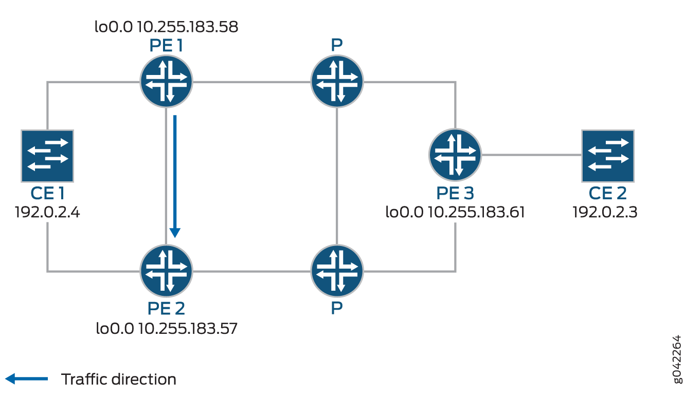
CE1 is multihomed to PE1 and PE2. There are two paths connecting CE1 and CE2. The working path is CE2-PE3-P-PE1-CE1, via pseudowire PW21. The protecting path is CE2-PE3-P-PE2-CE1, via pseudowire PW22 Traffic is flowing through the working path under normal circumstances. When the end-to-end OAM between CE1 and CE2 detects failure on the working path, traffic will be switched from the working path to the protecting path. The end-to-end failure detection and recovery relies on control plane hence should be relatively slow. To achieve faster protection, local repair mechanisms similar to those used by MPLS fast reroute should be used. In Figure 1 above, if link or node failed in the core network (like link failure on P-PE1, P-PE3, or node failure on P), the MPLS fast reroute will happen on the transport LSPs between PE1 and PE3. The failure could be locally repaired within tens of milliseconds. However, if link or node failure happens at the edge (like link failure on PE3-CE2 or node failure on PE3), there is no local repair currently so we have to rely on the CE1-CE2 end-to-end protection to repair the failure.
Device CE2—Traffic origin
Router PE3—Ingress PE router
Router PE1— (Primary) Egress PE router
Router PE2—Protector PE router
Device CE1—Traffic destination
When the link between CE1– PE1 goes downs, PE1 will briefly redirect that traffic towards CE1, to PE2. PE2 forwards it to CE1 until ingress router PE3 recalculates to forward the traffic to PE2.
Initially the traffic direction was; CE2 – PE3 – P – PE1 – CE1.
When the link between CE1– PE1 goes down, the traffic will be; CE2 – PE3 – P – PE1 – PE2 –CE1. PE3 then recalculates the path; CE2 – PE3 – P – PE2 – CE1.
- Configure RSVP on PE1, PE2, and PE3.[edit protocols]user@PE1# set interface alluser@PE2# set interface alluser@PE3# set interface all
- Configure MPLS.[edit protocols mpls]user@PE1# set interface alluser@PE2# set interface alluser@PE3# set interface all
- Set PE1 as primary and PE2 as protector nodes.[edit protocols mpls]user@PE1# set egress-protection context-identifier address primaryuser@PE2# set egress-protection context-identifier address protector
- Enable egress-protection on PE1 and PE2.[edit protocols bgp]user@PE1# set group ibgp family l2vpn egress-protectionuser@PE2# set group ibgp family l2vpn egress-protection
- Configure LDP and ISIS on PE1, PE2, and PE3.[edit protocols ldp]user@PE1# set interface alluser@PE2# set interface alluser@PE3# set interface all[edit protocols isis]user@PE1# set interface all point-to-pointuser@PE2# set interface all point-to-pointuser@PE3# set interface all point-to-point
- Configure a load balancing policy at PE1, PE2, and PE3.[edit]user@PE1# set policy-options policy-statement lb then load-balance per-packetuser@PE2# set policy-options policy-statement lb then load-balance per-packetuser@PE3# set policy-options policy-statement lb then load-balance per-packet
- Configure the routing options at PE1, PE2, and PE3, to
export routes based on the load balancing policy.[edit]user@PE1# set routing-options traceoptions file ro.loguser@PE1# set routing-options traceoptions flag normaluser@PE1# set routing-options traceoptions flag routeuser@PE1# set routing-options autonomous-system 100user@PE1# set routing-options forwarding-table export lb[edit]user@PE2# set routing-options traceoptions file ro.loguser@PE2# set routing-options traceoptions flag normaluser@PE2# set routing-options traceoptions flag routeuser@PE2# set routing-options autonomous-system 100user@PE2# set routing-options forwarding-table export lb[edit]user@PE3# set routing-options traceoptions file ro.loguser@PE3# set routing-options traceoptions flag normaluser@PE3# set routing-options traceoptions flag routeuser@PE3# set routing-options autonomous-system 100user@PE3# set routing-options forwarding-table export lb
- Configure BGP at PE1 to advertise nrli from the routing
instance with context-ID as next-hop.[edit]user@PE1# set routing-instances foo egress-protection context-identifier context-identifier
- Configure l2vpn at PE1, PE2, and PE3
At PE1:
[edit routing-instances]foo {instance-type l2vpn;egress-protection {context-identifier {198.51.100.0;}}interface ge-2/0/2.0;route-distinguisher 10.255.183.58:1;vrf-target target:9000:1;protocols {l2vpn {encapsulation-type ethernet-vlan;site foo {site-identifier 1;multi-homing;site-preference primary;interface ge-2/0/2.0 {remote-site-id 2;}}}}}At PE2:
[edit routing-instances]foo {instance-type l2vpn;egress-protection {protector;}interface ge-2/0/2.0;route-distinguisher 10.255.183.57:1;vrf-target target:9000:1;protocols {l2vpn {encapsulation-type ethernet-vlan;site foo{site-identifier 1;multi-homing;site-preference backup;interface ge-2/0/2.0 {remote-site-id 2;}}}}}At PE3:
[edit routing-instances]foo {instance-type l2vpn;interface ge-2/1/2.0;route-distinguisher 10.255.183.61:1;vrf-target target:9000:1;protocols {l2vpn {encapsulation-type ethernet-vlan;site foo {site-identifier 2;interface ge-2/1/2.0;}}}}