Konfiguration von SCU mit Layer-3-VPNs
Konfigurieren von SCU in einem Layer-3-VPN
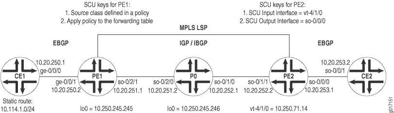
Abbildung 1 zeigt eine Layer-3-VPN-Topologie an. CE1 und CE2 sind Kunden-Edge-Router (CE), die über ein VPN über die Provider-Router PE1, P0 und PE2 verbunden sind. EBGP wird zwischen den Routern CE1 und PE1 eingerichtet, IBGP verbindet die Router PE1 und PE2 über einen IS-IS/MPLS/LDP-Kern und eine zweite EBGP-Verbindung fließt zwischen den Routern PE2 und CE2.
Beginnen Sie Ihr VPN auf Router CE1, indem Sie eine EBGP-Verbindung zu PE1 einrichten. Installieren Sie eine statische Route 10.114.1.0/24 , und kündigen Sie diese Route Ihrem EBGP-Nachbarn an.
Router CE1
[edit]
interfaces {
    ge-0/0/0 {
        unit 0 {
            family inet {
                address 10.20.250.1/30;
            }
        }
    }
}
routing-options {
    static {
        route 10.114.1.0/24 reject;
    }
    autonomous-system 100;
}
protocols {
    bgp {
        group to-pe1 {
            local-address 10.20.250.1;
            export inject-direct;
            peer-as 300;
            neighbor 10.20.250.2;
        }
    }
}
policy-options {
    policy-statement inject-direct {
        term 1 {
            from {
                protocol static;
                route-filter 10.114.1.0/24 exact;
            }
            then accept;
        }
        term 2 {
            from protocol direct;
            then accept;
        }
    }
}
Stellen Sie auf PE1 die EBGP-Verbindung zu CE1 über eine VRF-Routing-Instanz her. Legen Sie eine Exportrichtlinie für Ihre VRF-Instanz fest, die BGP-Datenverkehr in eine Community leitet, und eine Importrichtlinie, die Community-Datenverkehr von Ihrem VPN-Nachbarn akzeptiert. Konfigurieren Sie abschließend eine IBGP-Beziehung zum Router PE2, der über einen IS-IS-, MPLS- und LDP-Core ausgeführt wird.
Router PE1
[edit]
interfaces {
    ge-0/0/1 {
        unit 0 {
            family inet {
                address 10.20.250.2/30;
            }
        }
    }
    so-0/2/1 {
        unit 0 {
            family inet {
                address 10.20.251.1/30;
            }
            family iso;
            family mpls;
        }
    }
    lo0 {
        unit 0 {
            family inet {
                address 10.250.245.245/32;
            }
            family iso;
            family mpls;
        }
    }
}
routing-options {
    autonomous-system 300;
}
protocols {
    mpls {
        interface so-0/2/1;
    }
    bgp {
        group ibgp {
            type internal;
            local-address 10.250.245.245;
            family inet-vpn {
                unicast;
            }
            neighbor 10.250.71.14;
        }
    }
    isis {
        interface so-0/2/1;
    }
    ldp {
        interface so-0/2/1;
    }
}
policy-options {
    policy-statement red-import {
        from {
            protocol bgp;
            community red-com;
        }
        then accept;
    }
    policy-statement red-export {
        from protocol bgp;
        then {
            community add red-com;
            accept;
        }
    }
    community red-com members target:20:20;
}
routing-instances {
    red {
        instance-type vrf;
        interface ge-0/0/1.0;
        route-distinguisher 10.250.245.245:100;
        vrf-import red-import;
        vrf-export red-export;
        protocols {
            bgp {
                group to-ce1 {
                    local-address 10.20.250.2;
                    peer-as 100;
                    neighbor 10.20.250.1;
                }
            }
        }
    }
}
Verbinden Sie auf P0 die IBGP-Nachbarn, die sich bei PE1 und PE2 befinden. Denken Sie daran, VPN-bezogene Protokolle (MPLS, LDP und IGP) auf allen Schnittstellen einzubinden.
Router P0
[edit]
interfaces {
    so-0/1/0 {
        unit 0 {
            family inet {
                address 10.20.252.1/30;
            }
            family iso;
            family mpls;
        }
    }
    so-0/2/0 {
        unit 0 {
            family inet {
                address 10.20.251.2/30;
            }
            family iso;
            family mpls;
        }
    }
    lo0 {
        unit 0 {
            family inet {
                address 10.250.245.246/32;
            }
            family iso;
            family mpls;
        }
    }
}
routing-options {
    autonomous-system 300;
}
protocols {
    mpls {
        interface so-0/1/0;
        interface so-0/2/0;
    }
    isis {
        interface all;
    }
    ldp {
        interface all;
    }
}
Schließen Sie auf PE2 die IBGP-Beziehung zu Router PE1 ab. Stellen Sie über eine VRF-Routing-Instanz eine EBGP-Verbindung zu CE2 her. Legen Sie eine Exportrichtlinie für die VRF-Instanz fest, die BGP-Datenverkehr in einer Community platziert, und eine Importrichtlinie, die Community-Datenverkehr vom VPN-Nachbarn akzeptiert. Richten Sie als Nächstes eine Richtlinie ein, die die statische Route von CE1 zu einer Quellklasse namens . GOLD1 Exportieren Sie außerdem diese SCU-Richtlinie in die Weiterleitungstabelle. Legen Sie abschließend Ihre vt Schnittstelle als SCU-Eingabeschnittstelle und die CE-Schnittstelle so-0/0/0 als SCU-Ausgabeschnittstelle fest.
Router PE2
[edit]
interfaces {
    so-0/1/1 {
        unit 0 {
            family inet {
                address 10.20.252.2/30;
            }
            family iso;
            family mpls;
        }
    }
    so-0/0/0 {
        unit 0 {
            family inet {
                accounting {
                    source-class-usage {
                        output;
                    }
                }
                address 10.20.253.1/30;
            }
        }
    }
    vt-4/1/0 {
        unit 0 {
            family inet {
                accounting {
                    source-class-usage {
                        input;
                    }
                }
                address 10.250.71.14/32;
            }
            family iso;
            family mpls;
        }
    }
}
routing-options {
    autonomous-system 300;
    forwarding-table {
        export inject-customer2-dest-class;
    }
}
protocols {
    mpls {
        interface so-0/1/1;
        interface vt-4/1/0;
    }
    bgp {
        group ibgp {
            type internal;
            local-address 10.250.71.14;
            family inet-vpn {
                unicast;
            }
            neighbor 10.250.245.245;
        }
    }
    isis {
        interface so-0/1/1;
    }
    ldp {
        interface so-0/1/1;
    }
}
routing-instances {
    red {
        instance-type vrf;
        interface so-0/0/0.0;
        interface vt-4/1/0.0;
        route-distinguisher 10.250.71.14:100;
        vrf-import red-import;
        vrf-export red-export;
        protocols {
            bgp {
                group to-ce2 {
                    local-address 10.20.253.1;
                    peer-as 400;
                    neighbor 10.20.253.2;
                }
            }
        }
    }
}
policy-options {
    policy-statement red-import {
        from {
            protocol bgp;
            community red-com;
        }
        then accept;
    }
    policy-statement red-export {
        from protocol bgp;
        then {
            community add red-com;
            accept;
        }
    }
    policy-statement inject-customer2-dest-class {
        term term-gold1-traffic {
            from {
                route-filter 10.114.1.0/24 exact;
            }
            then source-class GOLD1;
        }
    }
    community red-com members target:20:20;
}
Schließen Sie auf Router CE2 den VPN-Pfad ab, indem Sie die EBGP-Verbindung zu PE2 beenden.
Router CE2
[edit]
interfaces {
    so-0/0/1 {
        unit 0 {
            family inet {
                address 10.20.253.2/30;
            }
        }
    }
}
routing-options {
    autonomous-system 400;
}
protocols {
    bgp {
        group to-pe2 {
            local-address 10.20.253.2;
            export inject-direct;
            peer-as 300;
            neighbor 10.20.253.1;
        }
    }
}
policy-options {
    policy-statement inject-direct {
        from {
            protocol direct;
        }
        then accept;
    }
}
Verifizieren Ihrer Arbeit
Verwenden Sie die folgenden Befehle, um zu überprüfen, ob SCU im Layer-3-VPN ordnungsgemäß funktioniert:
show interfaces interface-name statisticsshow interfaces source-class source-class-name interface-nameshow interfaces interface-nameextensive( |detail)show routeextensive( |detail)clear interface interface-name statistics
Sie sollten die SCU-Statistiken immer an der ausgehenden SCU-Schnittstelle überprüfen, auf der Sie die output Anweisung konfiguriert haben. Gehen Sie folgendermaßen vor, um die SCU-Funktionalität zu überprüfen:
Löschen Sie alle Zähler auf Ihrem SCU-fähigen Router, und stellen Sie sicher, dass sie leer sind.
Senden Sie einen Ping vom eingehenden CE-Router an den zweiten CE-Router, um SCU-Datenverkehr über die SCU-fähige VPN-Route zu generieren.
Stellen Sie sicher, dass die Zähler auf der ausgehenden Schnittstelle korrekt inkrementiert werden.
Der folgende Abschnitt zeigt die Ausgabe dieser Befehle, die mit dem Konfigurationsbeispiel verwendet werden.
user@pe2> clear interfaces statistics all

	user@pe2> show interfaces so-0/0/0.0 statistics
  	Logical interface so-0/0/0.0 (Index 6) (SNMP ifIndex 113)
    Flags: Point-To-Point SNMP-Traps Encapsulation: PPP
    Protocol inet, MTU: 4470
      Source class                             Packets                Bytes
 GOLD1                          0                    0
      Addresses, Flags: Is-Preferred Is-Primary

	user@pe2> show interfaces source-class GOLD1 so-0/0/0.0
    Protocol inet
      Source class                             Packets                Bytes
GOLD1                          0                    0

user@ce1> ping 10.20.253.2 source 10.114.1.1 rapid count 10000

user@scu>  show interfaces source-class GOLD1 so-0/0/0.0
    Protocol inet
      Source class                             Packets                Bytes
GOLD1                      20000              1680000

user@scu>  show interfaces so-0/0/0.0 statistics
  Logical interface so-0/0/0.0 (Index 6) (SNMP ifIndex 113)
    Flags: Point-To-Point SNMP-Traps Encapsulation: PPP
    Protocol inet, MTU: 4470
      Source class                             Packets                Bytes
GOLD1                      20000              1680000
      Addresses, Flags: Is-Preferred Is-Primary
         Destination: 10.20.253/24, Local: 10.20.253.1