Auf dieser Seite
Beispiel: MED mithilfe von Routenfiltern konfigurieren
In diesem Beispiel wird gezeigt, wie eine Richtlinie konfiguriert wird, die Routenfilter verwendet, um die MED-Metrik (Multiple Exit Discriminator) zu ändern, die in BGP-Aktualisierungsnachrichten angekündigt werden soll.
Anforderungen
Über die Geräteinitialisierung hinaus ist keine spezielle Konfiguration erforderlich, bevor Sie dieses Beispiel konfigurieren.
Überblick
Um eine Routenfilterrichtlinie zu konfigurieren, die die angekündigte MED-Metrik in BGP-Aktualisierungsnachrichten ändert, fügen Sie die Anweisung in die Richtlinienaktion ein.metric
Abbildung 1 zeigt ein typisches Netzwerk mit internen Peer-Sitzungen und mehreren Ausstiegspunkten zu einem benachbarten autonomen System (AS).
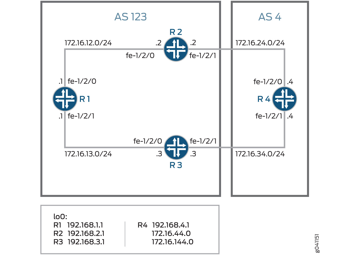
Gerät R4 verfügt über mehrere Loopback-Schnittstellen, die so konfiguriert sind, dass sie angekündigte Präfixe simulieren. Die zusätzlichen Loopback-Schnittstellenadressen sind 172.16.44.0/32 und 172.16.144.0/32. In diesem Beispiel wird gezeigt, wie Gerät R4 so konfiguriert wird, dass Gerät R3 für alle Routen außer 172.16.144.0 einen MED-Wert von 30 ankündigt. Für 172.16.144.0 wird Gerät 3 ein MED-Wert von 10 angekündigt. Ein MED-Wert von 20 wird für Gerät R2 angekündigt, unabhängig vom Routenpräfix.
Konfiguration
- CLI-Schnellkonfiguration
- Konfigurieren von Gerät R1
- Konfigurieren des Geräts R2
- Konfigurieren von Gerät R3
- Konfigurieren von Gerät R4
CLI-Schnellkonfiguration
Um dieses Beispiel schnell zu konfigurieren, kopieren Sie die folgenden Befehle, fügen Sie sie in eine Textdatei ein, entfernen Sie alle Zeilenumbrüche, ändern Sie alle Details, die für Ihre Netzwerkkonfiguration erforderlich sind, und kopieren Sie dann die Befehle und fügen Sie sie in die CLI auf Hierarchieebene ein.[edit]
Gerät R1
set interfaces fe-1/2/0 unit 1 family inet address 172.16.12.1/24
set interfaces fe-1/2/1 unit 2 family inet address 172.16.13.1/24
set interfaces lo0 unit 1 family inet address 192.168.1.1/32
set protocols bgp group internal type internal
set protocols bgp group internal local-address 192.168.1.1
set protocols bgp group internal export send-direct
set protocols bgp group internal neighbor 192.168.2.1
set protocols bgp group internal neighbor 192.168.3.1
set protocols ospf area 0.0.0.0 interface lo0.1 passive
set protocols ospf area 0.0.0.0 interface fe-1/2/0.1
set protocols ospf area 0.0.0.0 interface fe-1/2/1.2
set policy-options policy-statement send-direct term 1 from protocol direct
set policy-options policy-statement send-direct term 1 then accept
set routing-options autonomous-system 123
set routing-options router-id 192.168.1.1
Gerät R2
set interfaces fe-1/2/0 unit 3 family inet address 172.16.12.2/24
set interfaces fe-1/2/1 unit 4 family inet address 172.16.24.2/24
set interfaces lo0 unit 2 family inet address 192.168.2.1/32
set protocols bgp group internal type internal
set protocols bgp group internal local-address 192.168.2.1
set protocols bgp group internal export send-direct
set protocols bgp group internal neighbor 192.168.1.1
set protocols bgp group internal neighbor 192.168.3.1
set protocols bgp group external type external
set protocols bgp group external export send-direct
set protocols bgp group external peer-as 4
set protocols bgp group external neighbor 172.16.24.4
set protocols ospf area 0.0.0.0 interface lo0.2 passive
set protocols ospf area 0.0.0.0 interface fe-1/2/0.3
set protocols ospf area 0.0.0.0 interface fe-1/2/1.4
set policy-options policy-statement send-direct term 1 from protocol direct
set policy-options policy-statement send-direct term 1 then accept
set routing-options autonomous-system 123
set routing-options router-id 192.168.2.1
Gerät R3
set interfaces fe-1/2/0 unit 5 family inet address 172.16.13.3/24
set interfaces fe-1/2/1 unit 6 family inet address 172.16.34.3/24
set interfaces lo0 unit 3 family inet address 192.168.3.1/32
set protocols bgp group internal type internal
set protocols bgp group internal local-address 192.168.3.1
set protocols bgp group internal export send-direct
set protocols bgp group internal neighbor 192.168.1.1
set protocols bgp group internal neighbor 192.168.2.1
set protocols bgp group external type external
set protocols bgp group external export send-direct
set protocols bgp group external peer-as 4
set protocols bgp group external neighbor 172.16.34.4
set protocols ospf area 0.0.0.0 interface lo0.3 passive
set protocols ospf area 0.0.0.0 interface fe-1/2/0.5
set protocols ospf area 0.0.0.0 interface fe-1/2/1.6
set policy-options policy-statement send-direct term 1 from protocol direct
set policy-options policy-statement send-direct term 1 then accept
set routing-options autonomous-system 123
set routing-options router-id 192.168.3.1
Gerät R4
set interfaces fe-1/2/0 unit 7 family inet address 172.16.24.4/24
set interfaces fe-1/2/1 unit 8 family inet address 172.16.34.4/24
set interfaces lo0 unit 4 family inet address 192.168.4.1/32
set interfaces lo0 unit 4 family inet address 172.16.44.0/32
set interfaces lo0 unit 4 family inet address 172.16.144.0/32
set protocols bgp group external type external
set protocols bgp group external export send-direct
set protocols bgp group external peer-as 123
set protocols bgp group external neighbor 172.16.34.3 export med-10
set protocols bgp group external neighbor 172.16.34.3 export med-30
set protocols bgp group external neighbor 172.16.24.2 metric-out 20
set policy-options policy-statement med-10 from route-filter 172.16.144.0/32 exact
set policy-options policy-statement med-10 then metric 10
set policy-options policy-statement med-10 then accept
set policy-options policy-statement med-30 from route-filter 0.0.0.0/0 longer
set policy-options policy-statement med-30 then metric 30
set policy-options policy-statement med-30 then accept
set policy-options policy-statement send-direct term 1 from protocol direct
set policy-options policy-statement send-direct term 1 then accept
set routing-options autonomous-system 4
set routing-options router-id 192.168.4.1
Konfigurieren von Gerät R1
Schritt-für-Schritt-Anleitung
Im folgenden Beispiel müssen Sie durch verschiedene Ebenen in der Konfigurationshierarchie navigieren. Weitere Informationen zum Navigieren in der CLI finden Sie unter Verwenden des CLI-Editors im Konfigurationsmodus im Junos OS CLI-Benutzerhandbuch.Verwenden des CLI-Editors im Konfigurationsmodushttps://www.juniper.net/documentation/en_US/junos/information-products/pathway-pages/junos-cli/junos-cli.html
So konfigurieren Sie Gerät R1:
Konfigurieren Sie die Geräteschnittstellen.
[edit interfaces fe-1/2/0 unit 1]
user@R1# set family inet address 172.16.12.1/24
[edit interfaces fe-1/2/1 unit 2]
user@R1# set family inet address 172.16.13.1/24
[edit interfaces lo0 unit 1]
user@R1# set family inet address 192.168.1.1/32
Konfigurieren Sie BGP.
[edit protocols bgp group internal]
user@R1# set type internal
user@R1# set local-address 192.168.1.1
user@R1# set export send-direct
user@R1# set neighbor 192.168.2.1
user@R1# set neighbor 192.168.3.1
Konfigurieren Sie OSPF.
[edit protocols ospf area 0.0.0.0]
user@R1# set interface lo0.1 passive
user@R1# set interface fe-1/2/0.1
user@R1# set interface fe-1/2/1.2
Konfigurieren Sie eine Richtlinie, die direkte Routen akzeptiert.
Andere nützliche Optionen für dieses Szenario könnten darin bestehen, Routen zu akzeptieren, die über OSPF oder lokale Routen gelernt wurden.
[edit policy-options policy-statement send-direct term 1]
user@R1# set from protocol direct
user@R1# set then accept
Konfigurieren Sie die Router-ID und die AS-Nummer (Autonomous System).
[edit routing-options]
user@R1# set autonomous-system 123
user@R1# set router-id 192.168.1.1
Ergebnisse
Bestätigen Sie im Konfigurationsmodus Ihre Konfiguration, indem Sie die Befehle , , und eingeben.show interfacesshow protocolsshow policy-optionsshow routing-options Wenn die Ausgabe nicht die gewünschte Konfiguration anzeigt, wiederholen Sie die Anweisungen in diesem Beispiel, um die Konfiguration zu korrigieren.
user@R1# show interfaces
fe-1/2/0 {
    unit 1 {
        family inet {
            address 172.16.12.1/24;
        }
    }
}
fe-1/2/1 {
    unit 2 {
        family inet {
            address 172.16.13.1/24;
        }
    }
}
lo0 {
    unit 1 {
        family inet {
            address 192.168.1.1/32;
        }
    }
}
user@R1# show protocols
bgp {
    group internal {
        type internal;
        local-address 192.168.1.1;
        export send-direct;
        neighbor 192.168.2.1;
        neighbor 192.168.3.1;
    }
}
ospf {
    area 0.0.0.0 {
        interface lo0.1 {
            passive;
        }
        interface fe-1/2/0.1;
        interface fe-1/2/1.2;
    }
}
user@R1# show policy-options
policy-statement send-direct {
    term 1 {
        from protocol direct;
        then accept;
    }
}
user@R1# show routing-options
autonomous-system 123;
router-id 192.168.1.1;
Wenn Sie mit der Konfiguration des Geräts fertig sind, rufen Sie den Konfigurationsmodus auf .commit
Konfigurieren des Geräts R2
Schritt-für-Schritt-Anleitung
Im folgenden Beispiel müssen Sie durch verschiedene Ebenen in der Konfigurationshierarchie navigieren. Weitere Informationen zum Navigieren in der CLI finden Sie unter Verwenden des CLI-Editors im Konfigurationsmodus im Junos OS CLI-Benutzerhandbuch.Verwenden des CLI-Editors im Konfigurationsmodushttps://www.juniper.net/documentation/en_US/junos/information-products/pathway-pages/junos-cli/junos-cli.html
So konfigurieren Sie Gerät R2:
Konfigurieren Sie die Geräteschnittstellen.
[edit interfaces fe-1/2/0 unit 3]
user@R2# set family inet address 172.16.12.21/24
[edit interfaces fe-1/2/1 unit 4]
user@R2# set family inet address 172.16.24.2/24
[edit interfaces lo0 unit 2]
user@R2# set family inet address 192.168.2.1/32
Konfigurieren Sie BGP.
[edit protocols bgp group internal]
user@R2# set type internal
user@R2# set local-address 192.168.2.1
user@R2# set export send-direct
user@R2# set neighbor 192.168.1.1
user@R2# set neighbor 192.168.3.1
[edit protocols bgp group external]
user@R2# set type external
user@R2# set export send-direct
user@R2# set peer-as 4
user@R2# set neighbor 172.16.24.4
Konfigurieren Sie OSPF.
[edit protocols ospf area 0.0.0.0]
user@R2# set interface lo0.2 passive
user@R2# set interface fe-1/2/0.3
user@R2# set interface fe-1/2/1.4
Konfigurieren Sie eine Richtlinie, die direkte Routen akzeptiert.
Andere nützliche Optionen für dieses Szenario könnten darin bestehen, Routen zu akzeptieren, die über OSPF oder lokale Routen gelernt wurden.
[edit policy-options policy-statement send-direct term 1]
user@R2# set from protocol direct
user@R2# set then accept
Konfigurieren Sie die Router-ID und die AS-Nummer (Autonomous System).
[edit routing-options]
user@R2# set autonomous-system 123
user@R2# set router-id 192.168.2.1
Ergebnisse
Bestätigen Sie im Konfigurationsmodus Ihre Konfiguration, indem Sie die Befehle , , und eingeben.show interfacesshow protocolsshow policy-optionsshow routing-options Wenn die Ausgabe nicht die gewünschte Konfiguration anzeigt, wiederholen Sie die Anweisungen in diesem Beispiel, um die Konfiguration zu korrigieren.
user@R2# show interfaces
fe-1/2/0 {
    unit 3 {
        family inet {
            address 172.16.12.2/24;
        }
    }
}
fe-1/2/1 {
    unit 4 {
        family inet {
            address 172.16.24.2/24;
        }
    }
}
lo0 {
    unit 2 {
        family inet {
            address 192.168.2.1/32;
        }
    }
}
user@R2# show protocols
bgp {
    group internal {
        type internal;
        local-address 192.168.2.1;
        export send-direct;
        neighbor 192.168.1.1;
        neighbor 192.168.3.1;
    }
    group external {
        type external;
        export send-direct;
        peer-as 4;
        neighbor 172.16.24.4;
    }
}
ospf {
    area 0.0.0.0 {
        interface lo0.2 {
            passive;
        }
        interface fe-1/2/0.3;
        interface fe-1/2/1.4;
    }
}
user@R2# show policy-options
policy-statement send-direct {
    term 1 {
        from protocol direct;
        then accept;
    }
}
user@R2# show routing-options
autonomous-system 123;
router-id 192.168.2.1;
Wenn Sie mit der Konfiguration des Geräts fertig sind, rufen Sie den Konfigurationsmodus auf .commit
Konfigurieren von Gerät R3
Schritt-für-Schritt-Anleitung
Im folgenden Beispiel müssen Sie durch verschiedene Ebenen in der Konfigurationshierarchie navigieren. Weitere Informationen zum Navigieren in der CLI finden Sie unter Verwenden des CLI-Editors im Konfigurationsmodus im Junos OS CLI-Benutzerhandbuch.Verwenden des CLI-Editors im Konfigurationsmodushttps://www.juniper.net/documentation/en_US/junos/information-products/pathway-pages/junos-cli/junos-cli.html
So konfigurieren Sie Gerät R3:
Konfigurieren Sie die Geräteschnittstellen.
[edit interfaces fe-1/2/0 unit 5]
user@R3# set family inet address 172.16.13.3/24
[edit interfaces fe-1/2/1 unit 6]
user@R3# set family inet address 172.16.34.3/24
[edit interfaces lo0 unit 3]
user@R3# set family inet address 192.168.3.1/32
Konfigurieren Sie BGP.
[edit protocols bgp group internal]
user@R3# set type internal
user@R3# set local-address 192.168.3.1
user@R3# set export send-direct
user@R3# set neighbor 192.168.1.1
user@R3# set neighbor 192.168.2.1
[edit protocols bgp group external]
user@R3# set type external
user@R3# set export send-direct
user@R3# set peer-as 4
user@R3# set neighbor 172.16.34.4
Konfigurieren Sie OSPF.
[edit protocols ospf area 0.0.0.0]
user@R3# set interface lo0.3 passive
user@R3# set interface fe-1/2/0.5
user@R3# set interface fe-1/2/1.6
Konfigurieren Sie eine Richtlinie, die direkte Routen akzeptiert.
Andere nützliche Optionen für dieses Szenario könnten darin bestehen, Routen zu akzeptieren, die über OSPF oder lokale Routen gelernt wurden.
[edit policy-options policy-statement send-direct term 1]
user@R3# set from protocol direct
user@R3# set then accept
Konfigurieren Sie die Router-ID und die AS-Nummer (Autonomous System).
[edit routing-options]
user@R3# set autonomous-system 123
user@R3# set router-id 192.168.3.1
Ergebnisse
Bestätigen Sie im Konfigurationsmodus Ihre Konfiguration, indem Sie die Befehle , , und eingeben.show interfacesshow protocolsshow policy-optionsshow routing-options Wenn die Ausgabe nicht die gewünschte Konfiguration anzeigt, wiederholen Sie die Anweisungen in diesem Beispiel, um die Konfiguration zu korrigieren.
user@R3# show interfaces
fe-1/2/0 {
    unit 5 {
        family inet {
            address 172.16.13.3/24;
        }
    }
}
fe-1/2/1 {
    unit 6 {
        family inet {
            address 172.16.34.3/24;
        }
    }
}
lo0 {
    unit 3 {
        family inet {
            address 192.168.3.1/32;
        }
    }
}
user@R3# show protocols
bgp {
    group internal {
        type internal;
        local-address 192.168.3.1;
        export send-direct;
        neighbor 192.168.1.1;
        neighbor 192.168.2.1;
    }
    group external {
        type external;
        export send-direct;
        peer-as 4;
        neighbor 172.16.34.4;
    }
}
ospf {
    area 0.0.0.0 {
        interface lo0.3 {
            passive;
        }
        interface fe-1/2/0.5;
        interface fe-1/2/1.6;
    }
}
user@R3# show policy-options
policy-statement send-direct {
    term 1 {
        from protocol direct;
        then accept;
    }
}
user@R3# show routing-options
autonomous-system 123;
router-id 192.168.3.1;
Wenn Sie mit der Konfiguration des Geräts fertig sind, rufen Sie den Konfigurationsmodus auf .commit
Konfigurieren von Gerät R4
Schritt-für-Schritt-Anleitung
Im folgenden Beispiel müssen Sie durch verschiedene Ebenen in der Konfigurationshierarchie navigieren. Weitere Informationen zum Navigieren in der CLI finden Sie unter Verwenden des CLI-Editors im Konfigurationsmodus im Junos OS CLI-Benutzerhandbuch.Verwenden des CLI-Editors im Konfigurationsmodushttps://www.juniper.net/documentation/en_US/junos/information-products/pathway-pages/junos-cli/junos-cli.html
So konfigurieren Sie Gerät R4:
Konfigurieren Sie die Geräteschnittstellen.
[edit interfaces fe-1/2/0 unit 7]
user@R4# set family inet address 172.16.24.4/24
[edit interfaces fe-1/2/1 unit 8]
user@R4# set family inet address 172.16.34.4/24
[edit interfaces lo0 unit 4]
user@R4# set family inet address 192.168.4.1/32
user@R4# set family inet address 172.16.44.0/32
user@R4# set family inet address 172.16.144.0/32
Gerät R4 verfügt über mehrere Loopback-Schnittstellenadressen, um angekündigte Präfixe zu simulieren.
Konfigurieren Sie eine Richtlinie, die direkte Routen akzeptiert.
Andere nützliche Optionen für dieses Szenario könnten darin bestehen, Routen zu akzeptieren, die über OSPF oder lokale Routen gelernt wurden.
[edit policy-options policy-statement send-direct term 1]
user@R4# set from protocol direct
user@R4# set then accept
Konfigurieren Sie BGP.
[edit protocols bgp group external]
user@R4# set type external
user@R4# set export send-direct
user@R4# set peer-as 123
Konfigurieren Sie die beiden MED-Richtlinien.
[edit policy-options]
set policy-statement med-10 from route-filter 172.16.144.0/32 exact
set policy-statement med-10 then metric 10
set policy-statement med-10 then accept
set policy-statement med-30 from route-filter 0.0.0.0/0 longer
set policy-statement med-30 then metric 30
set policy-statement med-30 then accept
Konfigurieren Sie die beiden EBGP-Nachbarn, indem Sie die beiden MED-Richtlinien auf Gerät R3 und einen MED-Wert von 20 auf Gerät R2 anwenden.
[edit protocols bgp group external]
user@R4# set neighbor 172.16.34.3 export med-10
user@R4# set neighbor 172.16.34.3 export med-30
user@R4# set neighbor 172.16.24.2 metric-out 20
Konfigurieren Sie die Router-ID und die AS-Nummer (Autonomous System).
[edit routing-options]
user@R4# set autonomous-system 4
user@R4# set router-id 192.168.4.1
Ergebnisse
Bestätigen Sie im Konfigurationsmodus Ihre Konfiguration, indem Sie die Befehle , , und eingeben.show interfacesshow protocolsshow policy-optionsshow routing-options Wenn die Ausgabe nicht die gewünschte Konfiguration anzeigt, wiederholen Sie die Anweisungen in diesem Beispiel, um die Konfiguration zu korrigieren.
user@R4# show interfaces
fe-1/2/0 {
    unit 7 {
        family inet {
            address 172.16.24.4/24;
        }
    }
}
fe-1/2/1 {
    unit 8 {
        family inet {
            address 172.16.34.4/24;
        }
    }
}
lo0 {
    unit 4 {
        family inet {
            address 192.168.4.1/32;
            address 172.16.44.0/32;
            address 172.16.144.0/32;
        }
    }
}
user@R4# show protocols
bgp {
    group external {
        type external;
        export send-direct;
        peer-as 123;
        neighbor 172.16.24.2 {
            metric-out 20;
        }
        neighbor 172.16.34.3 {
            export [ med-10 med-30 ];
        }
    }
}
user@R4# show policy-options
policy-statement med-10 {
    from {
        route-filter 172.16.144.0/32 exact;
    }
    then {
        metric 10;
        accept;
    }
}
policy-statement med-30 {
    from {
        route-filter 0.0.0.0/0 longer;
    }
    then {
        metric 30;
        accept;
    }
}
policy-statement send-direct {
    term 1 {
        from protocol direct;
        then accept;
    }
}
user@R4# show routing-options
autonomous-system 4;
router-id 192.168.4.1;
Wenn Sie mit der Konfiguration des Geräts fertig sind, rufen Sie den Konfigurationsmodus auf .commit
Überprüfung
Vergewissern Sie sich, dass die Konfiguration ordnungsgemäß funktioniert.
- Überprüfen des aktiven Pfads von Gerät R1 zu Gerät R4
- Überprüfen, ob Gerät R4 seine Routen korrekt sendet
Überprüfen des aktiven Pfads von Gerät R1 zu Gerät R4
Zweck
Stellen Sie sicher, dass der aktive Pfad über Gerät R2 verläuft.
Was
Geben Sie im Betriebsmodus den Befehl ein.show route protocol bgp
user@R1> show route protocol bgp
inet.0: 13 destinations, 19 routes (13 active, 0 holddown, 0 hidden)
+ = Active Route, - = Last Active, * = Both

172.16.12.0/24       [BGP/170] 4d 01:13:32, localpref 100, from 192.168.2.1
                      AS path: I
                    > to 172.16.12.2 via fe-1/2/0.1
172.16.13.0/24       [BGP/170] 3d 05:36:10, localpref 100, from 192.168.3.1
                      AS path: I
                    > to 172.16.13.3 via fe-1/2/1.2
172.16.24.0/24       [BGP/170] 4d 01:13:32, localpref 100, from 192.168.2.1
                      AS path: I
                    > to 172.16.12.2 via fe-1/2/0.1
172.16.34.0/24       [BGP/170] 3d 05:36:10, localpref 100, from 192.168.3.1
                      AS path: I
                    > to 172.16.13.3 via fe-1/2/1.2
172.16.44.0/32     *[BGP/170] 00:06:03, MED 20, localpref 100, from 192.168.2.1
                      AS path: 4 I
                    > to 172.16.12.2 via fe-1/2/0.1
172.16.144.0/32 *[BGP/170] 00:06:03, MED 10, localpref 100, from 192.168.3.1
                      AS path: 4 I
                    > to 172.16.13.3 via fe-1/2/1.2
192.168.2.1/32      [BGP/170] 4d 01:13:32, localpref 100, from 192.168.2.1
                      AS path: I
                    > to 172.16.12.2 via fe-1/2/0.1
192.168.3.1/32      [BGP/170] 3d 05:36:10, localpref 100, from 192.168.3.1
                      AS path: I
                    > to 172.16.13.3 via fe-1/2/1.2
192.168.4.1/32     *[BGP/170] 00:06:03, MED 20, localpref 100, from 192.168.2.1
                      AS path: 4 I
                    > to 172.16.12.2 via fe-1/2/0.1
Bedeutung
Die Ausgabe zeigt, dass der bevorzugte Pfad zu den von Gerät R4 angekündigten Routen für alle Routen außer 172.16.144.0/32 über Gerät R2 führt. Für 172.16.144.0/32 führt der bevorzugte Pfad über Gerät R3.
Überprüfen, ob Gerät R4 seine Routen korrekt sendet
Zweck
Stellen Sie sicher, dass Gerät R4 Aktualisierungsnachrichten mit dem Wert 20 an Gerät R2 und dem Wert 30 an Gerät R3 sendet.
Was
Geben Sie im Betriebsmodus den Befehl ein.show route advertising-protocol bgp
user@R4> show route advertising-protocol bgp 172.16.24.2
inet.0: 11 destinations, 13 routes (11 active, 0 holddown, 0 hidden)
  Prefix                  Nexthop              MED     Lclpref    AS path
* 172.16.24.0/24           Self                 20                 I
* 172.16.34.0/24           Self                 20                 I
* 172.16.44.0/32          Self                 20                 I
* 172.16.144.0/32      Self                 20                 I
* 192.168.4.1/32          Self                 20                 I
user@R4> show route advertising-protocol bgp 172.16.34.3
inet.0: 11 destinations, 13 routes (11 active, 0 holddown, 0 hidden)
  Prefix                  Nexthop              MED     Lclpref    AS path
* 172.16.24.0/24           Self                 30                 I
* 172.16.34.0/24           Self                 30                 I
* 172.16.44.0/32          Self                 30                 I
* 172.16.144.0/32      Self                 10                 I
* 192.168.4.1/32          Self                 30                 I
Bedeutung
Die Spalte MED zeigt an, dass Gerät R4 die richtigen MED-Werte an seine beiden EBGP-Nachbarn sendet.