如何使用 EVPN 多宿主配置折叠主干
要求
此示例假定您有两个具有独立网络的数据中心(DC1 和 DC2)。此示例使用以下设备和软件:
DC1:
两台主干交换机:运行 Junos OS 18.4R2-S1.4 版的 QFX5120-48Y
两台 ToR 交换机:运行 Junos OS 18.1R3-S6.1 版的 EX4300-48T
两台安全设备:运行 Junos OS 18.2R3.4 版的 SRX345 设备(可选附加配置)
四台服务器
DC2:
两台主干交换机:运行 Junos OS 18.4R2-S1.4 版的 QFX5120-48Y
两台 ToR 交换机:运行 Junos OS 18.1R3-S6.1 版的 EX4300-48T
两台服务器
每对 ToR 交换机都应已配置为一个虚拟机箱。有关使用 EX4300 交换机组成虚拟机箱的详细信息,请参阅了解 EX 系列虚拟机箱 。此示例配置仅在 虚拟机箱 中的一个成员上的 ToR 虚拟机箱和两个主干设备之间使用多宿主聚合以太网链路。如果可能,为了获得更好的弹性,您可以使用来自不同 虚拟机箱 成员的接口连接 虚拟机箱 和主干设备之间的多宿主聚合以太网链路。
概述
使用此示例配置具有 ToR 交换机 EVPN 多宿主的折叠主干架构。我们有两个数据中心具有可选的数据中心互连 (DCI) 配置,一个可选的 SRX 群集以增加安全性,以及一个可选的 DHCP 中继配置。此配置示例说明如何在 DC1 中配置此架构。您可以在 DC2 中使用类似的配置。
拓扑学
在此部署中,有两个数据中心:DC1 和 DC2。数据中心网络配置为折叠式主干架构,使用 QFX5120 作为主干交换机。在这种情况下,我们建议您将 EVPN-VXLAN 交换矩阵限制在本地数据中心。
您可以选择使用底层中的第 3 层 DCI 连接数据中心。此用例不需要在数据中心之间进行第 2 层延伸。数据中心间流量仅适用于第 3 层,并通过 DC1 中的 SRX 群集路由以进行高级检测。
图 1 显示了此 NCE 中使用的组件之间的逻辑连接。
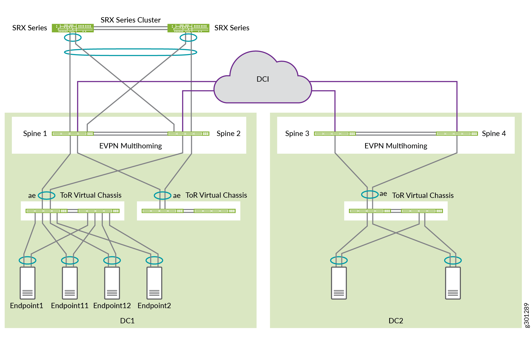
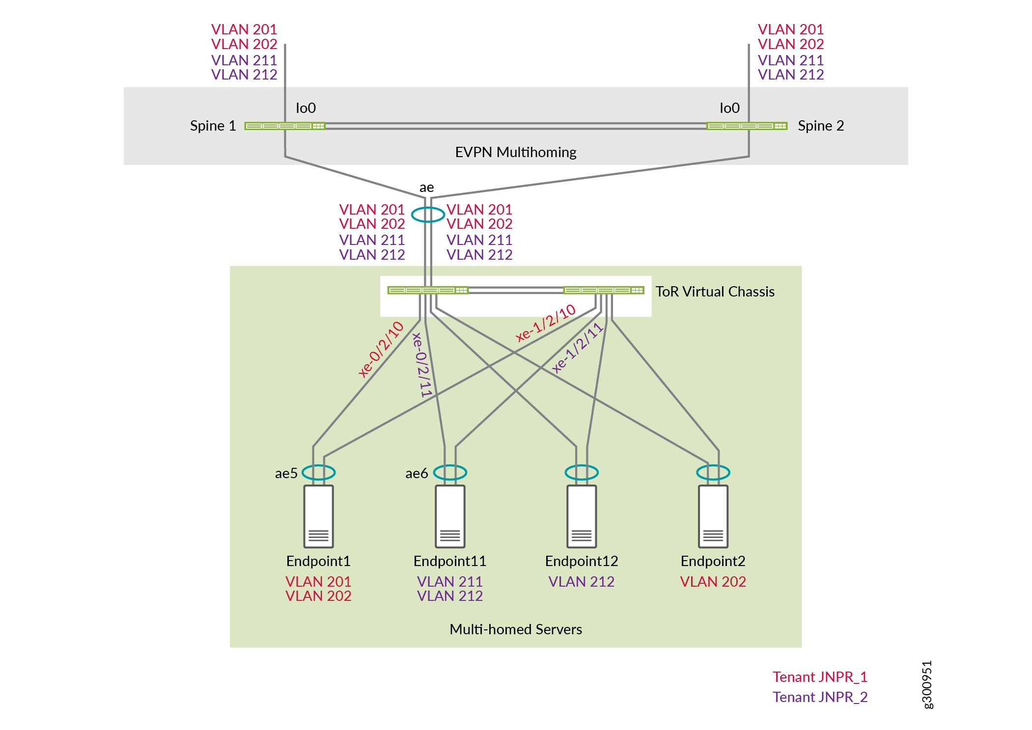
DC1 中有两个租户:JNPR1 和 JNPR2。为了确保安全性,DC1 中 JNPR1 和 JNPR2 之间的任何租户间流量都通过 SRX 防火墙群集路由。
DC1:
VLAN 201 和 202 属于 JNPR1。
VLAN 211 和 212 属于 JNPR2。
DC1 的服务器位于 VLAN 201、202、211 和 212 中。
DC2:
VLAN 221 和 222 属于默认租户,与默认路由实例相同。
DC2 的服务器位于 VLAN 221 和 222 中。
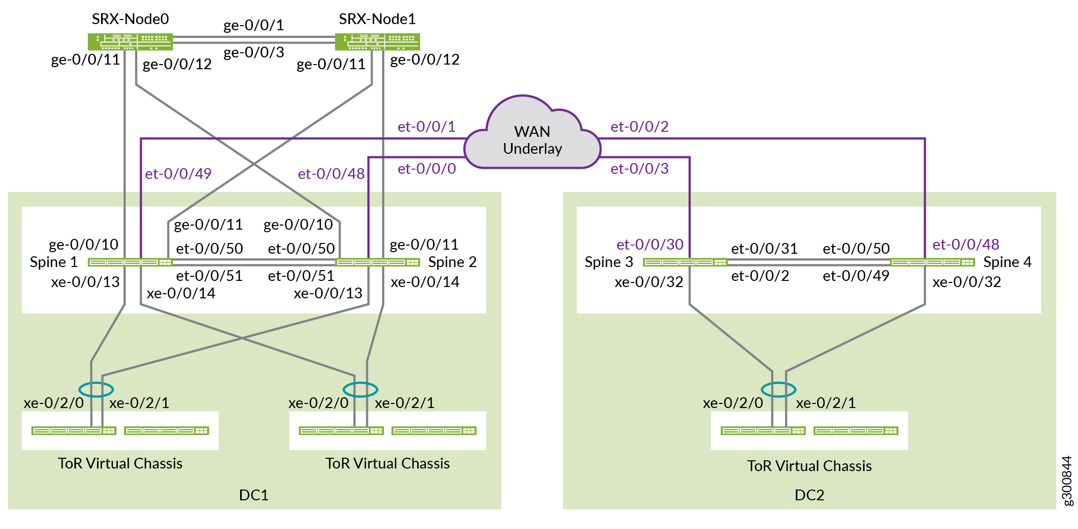
图 2 显示了此 NCE 中使用的组件之间的物理连接。
准备工作
在配置交换矩阵之前,您需要在设备上实施一些基本配置。
程序
分步过程
默认情况下,不会创建聚合以太网接口。您必须先设置聚合以太网接口的数量,然后才能对其进行配置。设置设备计数后,系统将创建该数量的空聚合以太网接口,每个接口都具有全球唯一的 MAC 地址。您可以通过将设备数量增加到设备上所需的 ESI-LAG 接口数来创建更多聚合以太网接口。
设置所有主干交换机和 ToR 交换机上的聚合以太网接口数量。
set chassis aggregated-devices ethernet device-count 15
默认情况下,QFX5120-48Y 上的端口 0 到 47 用作 10 千兆端口。SRX 设备仅支持 1 千兆位。将主干 1 和主干 2 上连接到 SRX 系列防火墙的端口配置为 1 千兆端口。在这种情况下,这些端口是 ge-0/0/10 和 ge-0/0/11。要在这些端口上启用 1 千兆,请配置四边形中第一个端口的速度,在本例中为 ge-0/0/8。
对主干 1 和主干 2 使用以下语句:
set chassis fpc 0 pic 0 port 8 speed 1G
注意:您只能按四通道(四端口组)配置 1 千兆和 25 千兆端口速度,而不能单独配置。所有端口在四边形内以单一速度运行。例如,如果您将端口 8 到 11 配置为 1 千兆以太网端口,并在端口 10 中插入 10 千兆 SFP+ 收发器,则不会为此端口创建接口。
自动速度检测模式可检测 100 千兆以太网接口和 40 千兆以太网接口,并自动对其进行通道化。默认情况下,自动通道化和速度检测处于启用状态。在此示例中,自动通道化会将每个 40 千兆以太网接口分成四个 10 千兆以太网接口。
禁用主干 3 上的端口 et-0/0/2 和 et-0/0/31 以及主干 4 上的端口 et-0/0/49 和 et-0/0/50 上的自动通道化,使其保持 40 千兆以太网接口。
主干 3:
set chassis fpc 0 pic 0 port 2 channel-speed disable-auto-speed-detection
set chassis fpc 0 pic 0 port 31 channel-speed disable-auto-speed-detection
主干 4:
set chassis fpc 0 pic 0 port 49 channel-speed disable-auto-speed-detection
set chassis fpc 0 pic 0 port 50 channel-speed disable-auto-speed-detection
配置底层
在此拓扑中,IP 交换矩阵仅位于两台主干交换机之间,如 图 3 所示。两台主干交换机通过点对点链路建立 EBGP 对等互连,以便相互交换环路地址。

配置主干 1
分步过程
在主干 1 上配置接口。
set interfaces et-0/0/50 description "* connected to DC1-Spine2"
set interfaces et-0/0/50 traps
set interfaces et-0/0/50 mtu 9216
set interfaces et-0/0/50 unit 0 family inet address 192.168.100.5/31
set interfaces et-0/0/51 description "* connected to DC1-Spine2"
set interfaces et-0/0/51 traps
set interfaces et-0/0/51 mtu 9216
set interfaces et-0/0/51 unit 0 family inet address 192.168.100.7/31
set interfaces lo0 unit 0 description "** DC1 Spine1 Loopback"
set interfaces lo0 unit 0 family inet address 192.168.255.13/32
配置 EBGP 底层。
set protocols bgp log-updown
set protocols bgp graceful-restart restart-time 30
set protocols bgp group UNDERLAY type external
set protocols bgp group UNDERLAY description "Connection to EBGP UNDERLAY"
set protocols bgp group UNDERLAY import UNDERLAY-IMPORT
set protocols bgp group UNDERLAY family inet unicast
set protocols bgp group UNDERLAY authentication-key "$ABC123"
set protocols bgp group UNDERLAY export UNDERLAY-EXPORT
set protocols bgp group UNDERLAY local-as 65013
set protocols bgp group UNDERLAY multipath multiple-as
set protocols bgp group UNDERLAY neighbor 192.168.100.4 peer-as 65012
set protocols bgp group UNDERLAY neighbor 192.168.100.6 peer-as 65012
配置导入和导出策略。
set policy-options policy-statement UNDERLAY-EXPORT term LOOPBACK from route-filter 192.168.255.0/24 orlonger
set policy-options policy-statement UNDERLAY-EXPORT term LOOPBACK then accept
set policy-options policy-statement UNDERLAY-EXPORT term DEFAULT then reject
set policy-options policy-statement UNDERLAY-IMPORT term LOOPBACK from route-filter 192.168.255.0/24 orlonger
set policy-options policy-statement UNDERLAY-IMPORT term LOOPBACK then accept
set policy-options policy-statement UNDERLAY-IMPORT term DEFAULT then reject
启用 ECMP 和 ECMP 快速重新路由保护。启用按流的负载平衡,这是使用
per-packet关键字执行的操作。set policy-options policy-statement ECMP-POLICY then load-balance per-packet set routing-options forwarding-table export ECMP-POLICY
如果链路出现故障,ECMP 会使用快速重新路由保护将数据包转发转移到运行链路,从而减少数据包丢失。快速重新路由保护更新 ECMP 接口集,无需等待路由表更新。下一次路由表更新时,可以添加链路较少的新 ECMP 集,或者路由可以指向下一个跃点。
set routing-options forwarding-table ecmp-fast-reroute
默认情况下,ARP 老化计时器设置为 20 分钟,MAC 老化计时器设置为 5 分钟。为避免 EVPN-VXLAN 环境中的 MAC 和 MAC-IP 绑定条目出现同步问题,请将 ARP 老化配置为比 MAC 老化更快。
set system arp aging-timer 5 set protocols l2-learning global-mac-ip-table-aging-time 300 set protocols l2-learning global-mac-table-aging-time 600
配置主干 2
分步过程
在主干 2 上重复主干 1 的配置。
在主干 2 上配置接口。
set interfaces et-0/0/50 description "* connected to DC1-Spine1" set interfaces et-0/0/50 traps set interfaces et-0/0/50 mtu 9216 set interfaces et-0/0/50 unit 0 family inet address 192.168.100.4/31 set interfaces et-0/0/51 description "* connected to DC1-Spine1" set interfaces et-0/0/51 traps set interfaces et-0/0/51 mtu 9216 set interfaces et-0/0/51 unit 0 family inet address 192.168.100.6/31 set interfaces lo0 unit 0 description "** DC1 Spine2 Loopback" set interfaces lo0 unit 0 family inet address 192.168.255.12/32
配置 EBGP 底层。
set protocols bgp log-updown set protocols bgp graceful-restart restart-time 30 set protocols bgp group UNDERLAY type external set protocols bgp group UNDERLAY description "EBGP UNDERLAY" set protocols bgp group UNDERLAY import UNDERLAY-IMPORT set protocols bgp group UNDERLAY family inet unicast set protocols bgp group UNDERLAY authentication-key "$ABC123" set protocols bgp group UNDERLAY export UNDERLAY-EXPORT set protocols bgp group UNDERLAY local-as 65012 set protocols bgp group UNDERLAY multipath multiple-as set protocols bgp group UNDERLAY neighbor 192.168.100.5 peer-as 65013 set protocols bgp group UNDERLAY neighbor 192.168.100.7 peer-as 65013
配置导入和导出策略。
set policy-options policy-statement UNDERLAY-EXPORT term LOOPBACK from route-filter 192.168.255.0/24 orlonger set policy-options policy-statement UNDERLAY-EXPORT term LOOPBACK then accept set policy-options policy-statement UNDERLAY-EXPORT term DEFAULT then reject set policy-options policy-statement UNDERLAY-IMPORT term LOOPBACK from route-filter 192.168.255.0/24 orlonger set policy-options policy-statement UNDERLAY-IMPORT term LOOPBACK then accept set policy-options policy-statement UNDERLAY-IMPORT term DEFAULT then reject
启用 ECMP 和 ECMP 快速重新路由保护。
set policy-options policy-statement ECMP-POLICY then load-balance per-packet set routing-options forwarding-table export ECMP-POLICY set routing-options forwarding-table ecmp-fast-reroute
为避免 EVPN-VXLAN 环境中的 MAC 和 MAC-IP 绑定条目出现同步问题,请将 ARP 老化配置为比 MAC 老化更快。
set system arp aging-timer 5
set protocols l2-learning global-mac-ip-table-aging-time 300
set protocols l2-learning global-mac-table-aging-time 600
验证底层
分步过程
验证两个 BGP 邻居会话是否均已在主干 1 上建立。
user@spine1> show bgp neighbor 192.168.100.4 Peer: 192.168.100.4+179 AS 65012 Local: 192.168.100.5+51424 AS 65013 Description: Connection to EBGP UNDERLAY Group: UNDERLAY Routing-Instance: master Forwarding routing-instance: master Type: External State: Established Flags: <Sync> Last State: OpenConfirm Last Event: RecvKeepAlive Last Error: Cease Export: [ UNDERLAY-EXPORT ] Import: [ UNDERLAY-IMPORT ] . . .
user@spine1> show bgp neighbor 192.168.100.6 Peer: 192.168.100.6+59705 AS 65012 Local: 192.168.100.7+179 AS 65013 Description: Connection to EBGP UNDERLAY Group: UNDERLAY Routing-Instance: master Forwarding routing-instance: master Type: External State: Established Flags: <Sync> Last State: OpenConfirm Last Event: RecvKeepAlive Last Error: Cease Export: [ UNDERLAY-EXPORT ] Import: [ UNDERLAY-IMPORT ] . . .
验证主干 2 (192.168.255.12) 的环路地址是否由主干 1 从两个 BGP 邻居会话接收。
user@spine1> show route receive-protocol bgp 192.168.100.4 inet.0: 17 destinations, 25 routes (17 active, 0 holddown, 0 hidden) Restart Complete Prefix Nexthop MED Lclpref AS path * 192.168.255.12/32 192.168.100.4 65012 I . . .
user@spine1> show route receive-protocol bgp 192.168.100.6 inet.0: 17 destinations, 25 routes (17 active, 0 holddown, 0 hidden) Restart Complete Prefix Nexthop MED Lclpref AS path 192.168.255.12/32 192.168.100.6 65012 I
user@spine1> show route 192.168.255.12 inet.0: 17 destinations, 25 routes (17 active, 0 holddown, 0 hidden) Restart Complete + = Active Route, - = Last Active, * = Both 192.168.255.12/32 *[BGP/170] 00:39:43, localpref 100, from 192.168.100.4 AS path: 65012 I, validation-state: unverified to 192.168.100.4 via et-0/0/50.0 > to 192.168.100.6 via et-0/0/51.0 [BGP/170] 00:39:43, localpref 100 AS path: 65012 I, validation-state: unverified > to 192.168.100.6 via et-0/0/51.0从主干 1 对其他主干主干设备的环路执行 Ping 命令。
user@spine1> ping 192.168.255.12 source 192.168.255.13 PING 192.168.255.12 (192.168.255.12): 56 data bytes 64 bytes from 192.168.255.12: icmp_seq=0 ttl=64 time=0.746 ms 64 bytes from 192.168.255.12: icmp_seq=1 ttl=64 time=0.699 ms 64 bytes from 192.168.255.12: icmp_seq=2 ttl=64 time=0.784 ms
配置叠加
本节介绍如何配置叠加。它包括 IBGP 对等互连以及虚拟网络的 VLAN 到 VXLAN 的映射。
配置主干 1
分步过程
在主干 1 和主干 2 环路地址之间配置 IBGP 对等互连。
set protocols bgp group EVPN_FABRIC type internal set protocols bgp group EVPN_FABRIC local-address 192.168.255.13 set protocols bgp group EVPN_FABRIC family evpn signaling set protocols bgp group EVPN_FABRIC authentication-key "$ABC123" set protocols bgp group EVPN_FABRIC local-as 65100 set protocols bgp group EVPN_FABRIC multipath set protocols bgp group EVPN_FABRIC bfd-liveness-detection minimum-interval 1000 set protocols bgp group EVPN_FABRIC bfd-liveness-detection multiplier 3 set protocols bgp group EVPN_FABRIC neighbor 192.168.255.12 set protocols bgp group EVPN_FABRIC vpn-apply-export
配置 VLAN 和 VLAN 到 VXLAN 的映射。
set vlans VLAN-201 description "jnpr_1 - bridge domain id 201" set vlans VLAN-201 vlan-id 201 set vlans VLAN-201 vxlan vni 5201 set vlans VLAN-202 description "jnpr_1 - bridge domain id 202" set vlans VLAN-202 vlan-id 202 set vlans VLAN-202 vxlan vni 5202 set vlans VLAN-211 description "jnpr_2 - bridge domain id 211" set vlans VLAN-211 vlan-id 211 set vlans VLAN-211 vxlan vni 5211 set vlans VLAN-212 description "jnpr_2 - bridge domain id 212" set vlans VLAN-212 vlan-id 212 set vlans VLAN-212 vxlan vni 5212
配置以下交换机选项:
虚拟隧道端点 (VTEP) 源接口。这是主干 1 上的环路地址。
此设备生成的路由的路由识别符。
路由目标。
set switch-options vtep-source-interface lo0.0 set switch-options route-distinguisher 192.168.255.13:1 set switch-options vrf-target target:1:999 set switch-options vrf-target auto
1 类 EVPN 路由使用下
vrf-target配置的路由目标。2 类和 3 类 EVPN 路由使用自动派生的每 VNI 路由目标进行导出和导入。配置 EVPN 协议。首先,将 VXLAN 配置为 EVPN 的数据平面封装。
set protocols evpn encapsulation vxlan
接下来,配置属于此 EVPN-VXLAN MP-BGP 域的 VNI。用于
set protocols evpn extended-vni-list all配置所有 VNI,或单独配置每个 VNI,如下所示。set protocols evpn extended-vni-list 5201 set protocols evpn extended-vni-list 5202 set protocols evpn extended-vni-list 5211 set protocols evpn extended-vni-list 5212
如果数据中心只有两台主干交换机,且彼此之间只有 BGP 邻居会话,则必须在两台主干交换机上禁用核心隔离。否则,如果一台主干交换机宕机,另一台主干交换机将丢失所有 BGP 邻接会话,从而将面向 ToR 的端口置于 LACP 备用模式,并导致流量完全丢失。有关详细信息,请参阅 裂脑状态 和 了解何时禁用 EVPN-VXLAN 核心隔离 。
set protocols evpn no-core-isolation
配置主干 2
分步过程
为避免 EVPN-VXLAN 环境中的 MAC 和 MAC-IP 绑定条目出现同步问题,请将 ARP 老化配置为比 MAC 老化更快。
set system arp aging-timer 5
set protocols l2-learning global-mac-ip-table-aging-time 300
set protocols l2-learning global-mac-table-aging-time 600
配置 IBGP 对等互连。
set protocols bgp group EVPN_FABRIC type internal set protocols bgp group EVPN_FABRIC local-address 192.168.255.12 set protocols bgp group EVPN_FABRIC family evpn signaling set protocols bgp group EVPN_FABRIC authentication-key "$ABC123" set protocols bgp group EVPN_FABRIC local-as 65100 set protocols bgp group EVPN_FABRIC multipath set protocols bgp group EVPN_FABRIC bfd-liveness-detection minimum-interval 1000 set protocols bgp group EVPN_FABRIC bfd-liveness-detection multiplier 3 set protocols bgp group EVPN_FABRIC neighbor 192.168.255.13 set protocols bgp group EVPN_FABRIC vpn-apply-export
配置 VLAN 和 VLAN 到 VXLAN 的映射。
set vlans VLAN-201 description "jnpr_1 - bridge domain id 201"
set vlans VLAN-201 vlan-id 201
set vlans VLAN-201 vxlan vni 5201

set vlans VLAN-202 description "jnpr_1 - bridge domain id 202"
set vlans VLAN-202 vlan-id 202
set vlans VLAN-202 vxlan vni 5202

set vlans VLAN-211 description "jnpr_2 - bridge domain id 211"
set vlans VLAN-211 vlan-id 211
set vlans VLAN-211 vxlan vni 5211

set vlans VLAN-212 description "jnpr_2 - bridge domain id 212"
set vlans VLAN-212 vlan-id 212
set vlans VLAN-212 vxlan vni 5212
配置以下交换机选项。
set switch-options vtep-source-interface lo0.0
set switch-options route-distinguisher 192.168.255.12:1
set switch-options vrf-target target:1:999
set switch-options vrf-target auto
配置 EVPN 协议。
set protocols evpn encapsulation vxlan
接下来,配置属于此 EVPN-VXLAN MP-BGP 域的 VNI。用于
set protocols evpn extended-vni-list all配置所有 VNI,或单独配置每个 VNI,如下所示。set protocols evpn extended-vni-list 5201 set protocols evpn extended-vni-list 5202 set protocols evpn extended-vni-list 5211 set protocols evpn extended-vni-list 5212
如果数据中心只有两台主干交换机,且彼此之间只有 BGP 邻居会话,则必须在两台主干交换机上禁用核心隔离。
set protocols evpn no-core-isolation
验证叠加
分步过程
验证主干 1 和主干 2 之间是否已建立 IBGP 对等互连。
user@spine1> show bgp neighbor 192.168.255.12
Peer: 192.168.255.12+179 AS 65100 Local: 192.168.255.13+62666 AS 65100
  Description: Overlay neighbor with peer
  Group: EVPN_FABRIC           Routing-Instance: master
  Forwarding routing-instance: master
  Type: Internal    State: Established    Flags:<Sync>
  Last State: OpenConfirm   Last Event: RecvKeepAlive
  Last Error: Hold Timer Expired Error
  Options: <Preference LocalAddress HoldTime AuthKey GracefulRestart LogUpDown AddressFamily Multipath LocalAS Rib-group Refresh>
  Authentication key is configured
  Address families configured: evpn
验证 EVPN 域的源 VTEP。
user@spine1> show ethernet-switching vxlan-tunnel-end-point source
Logical System Name       Id  SVTEP-IP         IFL   L3-Idx    SVTEP-Mode
    <default>                 0   192.168.255.13   lo0.0    0
    L2-RTT                   Bridge Domain              VNID     MC-Group-IP
    default-switch           VLAN-201+201               5201     0.0.0.0
    default-switch           VLAN-202+202               5202     0.0.0.0
    default-switch           VLAN-211+211               5211     0.0.0.0
    default-switch           VLAN-212+212               5212     0.0.0.0
验证所有源 VTEP 和远程 VTEP。
user@spine1> show interfaces vtep
Physical interface: vtep, Enabled, Physical link is Up
  Interface index: 641, SNMP ifIndex: 506
  Type: Software-Pseudo, Link-level type: VxLAN-Tunnel-Endpoint, MTU: Unlimited, Speed: Unlimited
  Device flags   : Present Running
  Link type      : Full-Duplex
  Link flags     : None
  Last flapped   : Never
    Input packets : 0
    Output packets: 0

  Logical interface vtep.32768 (Index 545) (SNMP ifIndex 548)
    Flags: Up SNMP-Traps 0x4000 Encapsulation: ENET2
    VXLAN Endpoint Type: Source, VXLAN Endpoint Address: 192.168.255.13, L2 Routing Instance: default-switch, L3 Routing Instance: default
    Input packets : 0
    Output packets: 0

  Logical interface vtep.32769 (Index 560) (SNMP ifIndex 550)
    Flags: Up SNMP-Traps Encapsulation: ENET2
    VXLAN Endpoint Type: Remote, VXLAN Endpoint Address: 192.168.255.12, L2 Routing Instance: default-switch, L3 Routing Instance: default
    Input packets : 9140
    Output packets: 0
    Protocol eth-switch, MTU: Unlimited
      Flags: Trunk-Mode
对第 3 层进行配置和分段
配置主干 1
分步过程
配置路由和转发选项。
注意:更改路由和转发选项(如
next-hop、overlay-ecmp或chained-composite-next-hop)会导致数据包转发引擎重新启动,从而中断所有转发操作。将下一跃点数设置为至少覆盖中预期的 ARP 条目数。有关配置
vxlan-routing next-hop的更多信息,请参阅下一跃点(VXLAN 路由)。使用语
overlay-ecmp句启用两级等价多路径下一跃点。如果还配置了纯 5 类路由,则第 3 层 EVPN-VXLAN 叠加网络需要此语句。强烈建议在启用纯 5 类路由时配置此语句。chained-composite-next-hop该配置是具有 VXLAN 封装的 EVPN 纯 5 型的必备配置。否则,PFE 将不会配置隧道下一跃点。将路由器 ID 配置为与用作 VTEP 源的环路 IP 地址和叠加 BGP 本地地址相同。
set forwarding-options vxlan-routing next-hop 32768
set forwarding-options vxlan-routing overlay-ecmp
set routing-options forwarding-table chained-composite-next-hop ingress evpn
set routing-options router-id 192.168.255.13
要启用默认网关功能,请为每个 IRB 接口配置一个唯一的 IP 地址和一个虚拟网关地址 (VGA),该地址必须是任播 IP 地址。当您为 VGA 指定 IPv4 地址时,第 3 层 VXLAN 网关会自动生成 00:00:5e:00:01:01:01 作为 MAC 地址。此示例说明如何手动配置虚拟网关 MAC 地址。在两个主干设备上为给定的 IRB 配置相同的虚拟网关 MAC 地址。
注意:如果 VGA IP 地址低于 IRB IP 地址,则必须使用
preferredIRB 配置中的选项,如此示例中所示。set interfaces irb unit 201 virtual-gateway-accept-data set interfaces irb unit 201 description "** L3 interface for VLAN-201 in jnpr_1" set interfaces irb unit 201 family inet address 192.168.201.3/24 virtual-gateway-address 192.168.201.1 set interfaces irb unit 201 family inet address 192.168.201.3/24 preferred set interfaces irb unit 201 virtual-gateway-v4-mac 3c:8c:93:2e:20:01 set vlans VLAN-201 l3-interface irb.201 set interfaces irb unit 202 virtual-gateway-accept-data set interfaces irb unit 202 description "** L3 interface for VLAN-202 in jnpr_1" set interfaces irb unit 202 family inet address 192.168.202.3/24 virtual-gateway-address 192.168.202.1 set interfaces irb unit 202 family inet address 192.168.202.3/24 preferred set interfaces irb unit 202 virtual-gateway-v4-mac 3c:8c:93:2e:20:02 set vlans VLAN-202 l3-interface irb.202 set interfaces irb unit 211 virtual-gateway-accept-data set interfaces irb unit 211 description "** L3 interface for VLAN-211 in jnpr_2" set interfaces irb unit 211 family inet address 192.168.211.3/24 virtual-gateway-address 192.168.211.1 set interfaces irb unit 211 family inet address 192.168.211.3/24 preferred set interfaces irb unit 211 virtual-gateway-v4-mac 3c:8c:93:2e:21:11 set vlans VLAN-211 l3-interface irb.211 set interfaces irb unit 212 virtual-gateway-accept-data set interfaces irb unit 212 description "** L3 interface for VLAN-212 in jnpr_2" set interfaces irb unit 212 family inet address 192.168.212.3/24 virtual-gateway-address 192.168.212.1 set interfaces irb unit 212 family inet address 192.168.212.3/24 preferred set interfaces irb unit 212 virtual-gateway-v4-mac 3c:8c:93:2e:21:12 set vlans VLAN-212 l3-interface irb.212
您将在每个主干设备的 IRB 接口上配置相同的任播 IRB IP 和 MAC 地址。由于主干设备在折叠式主干架构中同时充当主干设备和叶设备,因此是唯一需要了解 IRB 接口的设备。禁用 IRB 接口向其他设备播发。
set protocols evpn default-gateway do-not-advertise
将属于不同租户的 IRB 放入各自的路由实例中。这允许相同路由实例中的 IRB 共享路由表。因此,路由实例中的 IRB 可以相互路由。不同路由实例中的 IRB 可以通过 SRX 防火墙等外部安全策略实施器相互通信,或者如果我们在路由实例之间显式泄露路由,则可以相互通信。
set routing-instances JNPR_1_VRF description "VRF for tenant jnpr_1"
set routing-instances JNPR_1_VRF instance-type vrf
set routing-instances JNPR_1_VRF interface irb.201
set routing-instances JNPR_1_VRF interface irb.202
set routing-instances JNPR_1_VRF vrf-table-label
set routing-instances JNPR_1_VRF routing-options multipath


set routing-instances JNPR_2_VRF description "VRF for tenant jnpr_2"
set routing-instances JNPR_2_VRF instance-type vrf
set routing-instances JNPR_2_VRF interface irb.211
set routing-instances JNPR_2_VRF interface irb.212
set routing-instances JNPR_2_VRF vrf-table-label
set routing-instances JNPR_2_VRF routing-options multipath
为路由实例配置 5 类 VNI。为 EVPN-VXLAN 设置路由实例时,必须包括环路接口及其 IP 地址。如果省略环路接口和关联的 IP 地址,则无法处理 EVPN 控制数据包。
set routing-instances JNPR_1_VRF protocols evpn ip-prefix-routes advertise direct-nexthop
	set routing-instances JNPR_1_VRF protocols evpn ip-prefix-routes encapsulation vxlan
set routing-instances JNPR_1_VRF protocols evpn ip-prefix-routes vni 1101
set routing-instances JNPR_1_VRF protocols evpn ip-prefix-routes export T5_EXPORT

set routing-instances JNPR_2_VRF protocols evpn ip-prefix-routes advertise direct-nexthop
set routing-instances JNPR_2_VRF protocols evpn ip-prefix-routes encapsulation vxlan
set routing-instances JNPR_2_VRF protocols evpn ip-prefix-routes vni 1102
set routing-instances JNPR_2_VRF protocols evpn ip-prefix-routes export T5_EXPORT

set interfaces lo0 unit 1 description "Tenant 1 T5 Loopback"
set interfaces lo0 unit 1 family inet address 192.168.255.21/32
set routing-instances JNPR_1_VRF interface lo0.1

set interfaces lo0 unit 2 description "Tenant 2 T5 Loopback"
set interfaces lo0 unit 2 family inet address 192.168.255.22/32
set routing-instances JNPR_2_VRF interface lo0.2

set policy-options policy-statement T5_EXPORT term 1 from protocol direct
set policy-options policy-statement T5_EXPORT term 1 then accept
set policy-options policy-statement T5_EXPORT term 2 from protocol bgp
set policy-options policy-statement T5_EXPORT term 2 then accept
配置主干 2
分步过程
配置路由和转发选项。
注意:更改路由和转发选项(如
next-hop、overlay-ecmp或chained-composite-next-hop)会导致数据包转发引擎重新启动,从而中断所有转发操作。set forwarding-options vxlan-routing next-hop 32768 set forwarding-options vxlan-routing overlay-ecmp set routing-options forwarding-table chained-composite-next-hop ingress evpn set routing-options router-id 192.168.255.12
配置 IRB。
set interfaces irb unit 201 virtual-gateway-accept-data
set interfaces irb unit 201 description "** L3 interface for VLAN-201 in jnpr_1"
set interfaces irb unit 201 family inet address 192.168.201.2/24 virtual-gateway-address 192.168.201.1
set interfaces irb unit 201 family inet address 192.168.201.2/24 preferred
set interfaces irb unit 201 virtual-gateway-v4-mac 3c:8c:93:2e:20:01
set vlans VLAN-201 l3-interface irb.201

set interfaces irb unit 202 virtual-gateway-accept-data
set interfaces irb unit 202 description "** L3 interface for VLAN-202 in jnpr_1"
set interfaces irb unit 202 family inet address 192.168.202.2/24 virtual-gateway-address 192.168.202.1
set interfaces irb unit 202 family inet address 192.168.202.2/24 preferred
set interfaces irb unit 202 virtual-gateway-v4-mac 3c:8c:93:2e:20:02
set vlans VLAN-202 l3-interface irb.202

set interfaces irb unit 211 virtual-gateway-accept-data
set interfaces irb unit 211 description "** L3 interface for VLAN-211 in jnpr_2"
set interfaces irb unit 211 family inet address 192.168.211.2/24 virtual-gateway-address 192.168.211.1
set interfaces irb unit 211 family inet address 192.168.211.2/24 preferred
set interfaces irb unit 211 virtual-gateway-v4-mac 3c:8c:93:2e:21:11
set vlans VLAN-211 l3-interface irb.211

set interfaces irb unit 212 virtual-gateway-accept-data
set interfaces irb unit 212 description "** L3 interface for VLAN-212 in jnpr_2"
set interfaces irb unit 212 family inet address 192.168.212.2/24 virtual-gateway-address 192.168.212.1
set interfaces irb unit 212 family inet address 192.168.212.2/24 preferred
set interfaces irb unit 212 virtual-gateway-v4-mac 3c:8c:93:2e:21:12
set vlans VLAN-212 l3-interface irb.212
由于在两台主干交换机的 IRB 接口上配置了相同的任播 IRB IP 和 MAC 地址,因此请禁用 IRB 接口向其他设备播发。
set protocols evpn default-gateway do-not-advertise
将属于不同租户的 IRB 放入各自的路由实例中。
set routing-instances JNPR_1_VRF description "VRF for tenant jnpr_1"
set routing-instances JNPR_1_VRF instance-type vrf
set routing-instances JNPR_1_VRF interface irb.201
set routing-instances JNPR_1_VRF interface irb.202
set routing-instances JNPR_1_VRF vrf-table-label
set routing-instances JNPR_1_VRF routing-options multipath

set routing-instances JNPR_2_VRF description "VRF for tenant jnpr_2"
set routing-instances JNPR_2_VRF instance-type vrf
set routing-instances JNPR_2_VRF interface irb.211
set routing-instances JNPR_2_VRF interface irb.212
set routing-instances JNPR_2_VRF vrf-table-label
set routing-instances JNPR_2_VRF routing-options multipath
为路由实例配置 5 类 VNI。
set routing-instances JNPR_1_VRF protocols evpn ip-prefix-routes advertise direct-nexthop
set routing-instances JNPR_1_VRF protocols evpn ip-prefix-routes encapsulation vxlan
set routing-instances JNPR_1_VRF protocols evpn ip-prefix-routes vni 1101
set routing-instances JNPR_1_VRF protocols evpn ip-prefix-routes export T5_EXPORT

set routing-instances JNPR_2_VRF protocols evpn ip-prefix-routes advertise direct-nexthop
set routing-instances JNPR_2_VRF protocols evpn ip-prefix-routes encapsulation vxlan
set routing-instances JNPR_2_VRF protocols evpn ip-prefix-routes vni 1102
set routing-instances JNPR_2_VRF protocols evpn ip-prefix-routes export T5_EXPORT

set interfaces lo0 unit 101 description "Tenant 1 T5 Loopback"
set interfaces lo0 unit 101 family inet address 192.168.255.31/32
set routing-instances JNPR_1_VRF interface lo0.101

set interfaces lo0 unit 102 description "Tenant 2 T5 Loopback"
set interfaces lo0 unit 102 family inet address 192.168.255.32/32
set routing-instances JNPR_2_VRF interface lo0.102

set policy-options policy-statement T5_EXPORT term 1 from protocol direct
set policy-options policy-statement T5_EXPORT term 1 then accept
set policy-options policy-statement T5_EXPORT term 2 from protocol bgp
set policy-options policy-statement T5_EXPORT term 2 then accept
为 ToR 交换机配置 EVPN 多宿主
EVPN 多宿主使用 ESI。ESI 是启用 EVPN LAG 服务器多宿主的必需属性。ESI 值编码为 10 字节整数,用于标识多宿主分段。在连接到 ToR 交换机的所有主干交换机上启用的相同 ESI 值会形成 EVPN LAG。此 EVPN LAG 支持朝向 ToR 交换机的主动/主动多宿主。
ToR 交换机(在本例中为 ToR 虚拟机箱实现)使用 LAG 连接到两台主干交换机。如 图 4 所示,ToR1 通过 LAG ae1 连接到主干交换机。主干交换机上的此 LAG 由 EVPN 多宿主功能启用。

配置主干 1
分步过程
默认情况下,不会创建聚合以太网接口。您必须先设置交换机上的聚合以太网接口数量,然后才能对其进行配置。
set chassis aggregated-devices ethernet device-count 15
set interfaces ae1 description "to ToR1"
set interfaces ae1 mtu 9216
配置 ESI。在两台主干交换机上设置相同。启用全活动模式。
set interfaces ae1 esi 00:00:00:00:00:00:00:00:01:01
set interfaces ae1 esi all-active
set interfaces ae1 aggregated-ether-options link-speed 10g
set interfaces ae1 aggregated-ether-options lacp active
set interfaces ae1 aggregated-ether-options lacp periodic fast
注意:您还可以自动派生 ESI。在此示例中,您将手动配置 ESI。
配置 LACP 系统 ID。 在两台主干交换机上设置相同的值,以向 ToR 交换机指示指向这两台主干交换机的上行链路属于同一 LAG 束。因此,ToR 交换机将两台主干交换机的上行链路放在同一个 LAG 束中,并在成员链路之间共享流量。
set interfaces ae1 aggregated-ether-options lacp system-id 00:00:00:00:01:01
set interfaces ae1 unit 0 family ethernet-switching interface-mode trunk
set interfaces ae1 unit 0 family ethernet-switching vlan members VLAN-201
set interfaces ae1 unit 0 family ethernet-switching vlan members VLAN-202
set interfaces ae1 unit 0 family ethernet-switching vlan members VLAN-211
set interfaces ae1 unit 0 family ethernet-switching vlan members VLAN-212
将主干 1 上连接到 ToR 1 的物理接口配置为 ae1 LAG 的成员。
set interfaces xe-0/0/13 ether-options 802.3ad ae1
配置主干 2
分步过程
设置交换机上的聚合以太网接口数量。
set chassis aggregated-devices ethernet device-count 15
set interfaces ae1 description "to ToR1"
set interfaces ae1 mtu 9216
配置 ESI。在两台主干交换机上设置相同。启用全活动模式。
set interfaces ae1 esi 00:00:00:00:00:00:00:00:01:01
set interfaces ae1 esi all-active
set interfaces ae1 aggregated-ether-options link-speed 10g
set interfaces ae1 aggregated-ether-options lacp active
set interfaces ae1 aggregated-ether-options lacp periodic fast
配置 LACP 系统 ID。在两台主干交换机上将其设置为相同。
set interfaces ae1 aggregated-ether-options lacp system-id 00:00:00:00:01:01
set interfaces ae1 unit 0 family ethernet-switching interface-mode trunk
set interfaces ae1 unit 0 family ethernet-switching vlan members VLAN-201
set interfaces ae1 unit 0 family ethernet-switching vlan members VLAN-202
set interfaces ae1 unit 0 family ethernet-switching vlan members VLAN-211
set interfaces ae1 unit 0 family ethernet-switching vlan members VLAN-212
将主干 2 上连接到 ToR 1 的物理接口配置为 ae1 LAG 的成员。
set interfaces xe-0/0/13 ether-options 802.3ad ae1
配置 ToR 1
分步过程
默认情况下,不会创建聚合以太网接口。您必须先设置交换机上的聚合以太网接口数量,然后才能对其进行配置。
set chassis aggregated-devices ethernet device-count 4
配置聚合以太网接口。
set interfaces xe-0/2/0 ether-options 802.3ad ae1
set interfaces xe-0/2/1 ether-options 802.3ad ae1

set interfaces ae1 aggregated-ether-options lacp active
set interfaces ae1 unit 0 family ethernet-switching interface-mode trunk
set interfaces ae1 unit 0 family ethernet-switching vlan members VLAN-201
set interfaces ae1 unit 0 family ethernet-switching vlan members VLAN-202
set interfaces ae1 unit 0 family ethernet-switching vlan members VLAN-211
set interfaces ae1 unit 0 family ethernet-switching vlan members VLAN-212
配置 VLAN。
set vlans VLAN-201 vlan-id 201
set vlans VLAN-202 vlan-id 202
set vlans VLAN-211 vlan-id 211
set vlans VLAN-212 vlan-id 212
验证 EVPN 多宿主
分步过程
检查 ae1 的状态以及与 LAG 关联的 ESI。
user@spine1> show interfaces ae1
Physical interface: ae1, Enabled, Physical link is Up
  Interface index: 689, SNMP ifIndex: 552
  Description: to ToR1
  Link-level type: Ethernet, MTU: 9216, Speed: 10Gbps, BPDU Error: None, Ethernet-Switching Error: None, MAC-REWRITE Error: None, Loopback: Disabled, Source filtering: Disabled, Flow control: Disabled, Minimum links needed: 1,
  Minimum bandwidth needed: 1bps
  Device flags   : Present Running
  Interface flags: SNMP-Traps Internal: 0x4000
  Current address: 3c:8c:93:2e:a9:80, Hardware address: 3c:8c:93:2e:a9:80
  Ethernet segment value: 00:00:00:00:00:00:00:00:01:01, Mode: all-active
  Last flapped   : 2019-11-10 14:50:49 PST (00:26:56 ago)
  Input rate     : 624 bps (0 pps)
  Output rate    : 936 bps (1 pps)
  ...
验证 ae1 的成员是否正在收集和分发。
user@spine1> show lacp interfaces ae1
Aggregated interface: ae1
    LACP state:       Role   Exp   Def  Dist  Col  Syn  Aggr  Timeout  Activity
      xe-0/0/13      Actor    No    No   Yes  Yes  Yes   Yes     Fast    Active
      xe-0/0/13    Partner    No    No   Yes  Yes  Yes   Yes     Fast    Active
    LACP protocol:        Receive State  Transmit State          Mux State
      xe-0/0/13                 Current   Fast periodic Collecting distributing
验证 EVPN 实例中 EVPN 多宿主的状态是否
Resolved在主干 1 上。您还可以查看哪台主干交换机是 BUM 流量的指定转发器。user@spine1> show evpn instance extensive Instance: __default_evpn__ Route Distinguisher: 192.168.255.13:0 Number of bridge domains: 0 Number of neighbors: 1 Address MAC MAC+IP AD IM ES Leaf-label 192.168.255.12 0 0 0 0 2 Instance: default-switch Route Distinguisher: 192.168.255.13:1 Encapsulation type: VXLAN Duplicate MAC detection threshold: 5 Duplicate MAC detection window: 180 MAC database status Local Remote MAC advertisements: 6 10 MAC+IP advertisements: 10 10 Default gateway MAC advertisements: 8 0 Number of local interfaces: 5 (3 up) Interface name ESI Mode Status AC-Role .local..6 00:00:00:00:00:00:00:00:00:00 single-homed Up Root ae1.0 00:00:00:00:00:00:00:00:01:01 all-active Up Root ... Number of neighbors: 1 Address MAC MAC+IP AD IM ES Leaf-label 192.168.255.12 10 10 8 4 0 Number of ethernet segments: 10 ESI: 00:00:00:00:00:00:00:00:01:01 Status: Resolved by IFL ae1.0 Local interface: ae1.0, Status: Up/Forwarding Number of remote PEs connected: 1 Remote PE MAC label Aliasing label Mode 192.168.255.12 5212 0 all-active DF Election Algorithm: MOD based Designated forwarder: 192.168.255.13 Backup forwarder: 192.168.255.12 Last designated forwarder update: Nov 10 14:50:49验证 ae1 接口的所有成员链路是否都在 ToR 1 上收集和分发。
user@tor1> show lacp interfaces
Aggregated interface: ae1
    LACP state:       Role   Exp   Def  Dist  Col  Syn  Aggr  Timeout  Activity
      xe-0/2/0       Actor    No    No   Yes  Yes  Yes   Yes     Fast    Active
      xe-0/2/0     Partner    No    No   Yes  Yes  Yes   Yes     Fast    Active
      xe-0/2/1       Actor    No    No   Yes  Yes  Yes   Yes     Fast    Active
      xe-0/2/1     Partner    No    No   Yes  Yes  Yes   Yes     Fast    Active
    LACP protocol:        Receive State  Transmit State          Mux State
      xe-0/2/0                  Current   Fast periodic Collecting distributing
      xe-0/2/1                  Current   Fast periodic Collecting distributing
为服务器配置多宿主
将服务器多宿主到 ToR 虚拟机箱,以实现冗余和负载共享。服务器使用 LAG 连接到两台 ToR 虚拟机箱成员交换机。
如 图 5 所示,端点 1 通过 LAG ae5 连接到 ToR 虚拟机箱,属于JNPR_1租户。端点 11 通过 LAG ae6 连接到 ToR 虚拟机箱,属于JNPR_2租户。
配置 ToR 1
分步过程
由于 ToR 交换机是在虚拟机箱中配置的,因此您只需在主交换机上提交配置即可。在此示例中,ToR 1 是主开关。
在连接到端点 1 的接口上配置 LAG:ToR 1 上的接口 xe-0/2/10 和 ToR 2 上的接口 xe-1/2/10。端点 1 属于 VLAN 201 和 202。
set interfaces xe-0/2/10 ether-options 802.3ad ae5
set interfaces xe-1/2/10 ether-options 802.3ad ae5

set interfaces ae5 aggregated-ether-options lacp active
set interfaces ae5 description "Connected to Endpoint1"
set interfaces ae5 unit 0 family ethernet-switching interface-mode trunk
set interfaces ae5 unit 0 family ethernet-switching vlan members VLAN-201
set interfaces ae5 unit 0 family ethernet-switching vlan members VLAN-202
在连接到端点 11 的接口上配置 LAG。端点 11 属于 VLAN 211 和 212。
set interfaces xe-0/2/11 ether-options 802.3ad ae6
set interfaces xe-1/2/11 ether-options 802.3ad ae6

set interfaces ae6 aggregated-ether-options lacp active
set interfaces ae6 description "Connected to Endpoint11"
set interfaces ae6 unit 0 family ethernet-switching interface-mode trunk
set interfaces ae6 unit 0 family ethernet-switching vlan members VLAN-211
set interfaces ae6 unit 0 family ethernet-switching vlan members VLAN-212
验证服务器连接
使用此部分验证服务器是否通过 ToR 和主干交换机相互连接。如何执行此操作取决于它们是同一 VLAN 的一部分还是两个不同的 VLAN。
如上一节所述,我们建议将服务器多宿主到 ToR 交换机,以实现冗余和负载共享。为简单起见,本节介绍单宿主服务器。
验证 VLAN 内服务器连接
分步过程
验证两个端点的 MAC 地址是否显示在两个 ToR 交换机上的以太网交换表中。
user@tor1> show ethernet-switching table MAC flags (S - static MAC, D - dynamic MAC, L - locally learned, P - Persistent static, C - Control MAC SE - statistics enabled, NM - non configured MAC, R - remote PE MAC, O - ovsdb MAC) Ethernet switching table : 4 entries, 4 learned Routing instance : default-switch Vlan MAC MAC Age Logical NH RTR name address flags interface Index ID VLAN-201 f4:b5:2f:40:9f:01 D - ae1.0 0 0 VLAN-202 00:10:94:00:01:01 D - xe-0/2/2.0 0 0 VLAN-202 00:10:94:00:01:02 D - ae1.0 0 0 VLAN-202 3c:8c:93:2e:a8:c0 D - ae1.0 0 0user@tor2> show ethernet-switching table MAC flags (S - static MAC, D - dynamic MAC, L - locally learned, P - Persistent static, C - Control MAC SE - statistics enabled, NM - non configured MAC, R - remote PE MAC, O - ovsdb MAC) Ethernet switching table : 4 entries, 4 learned Routing instance : default-switch Vlan MAC MAC Age Logical NH RTR name address flags interface Index ID VLAN-201 f4:b5:2f:40:9f:01 D - ae1.0 0 0 VLAN-202 00:10:94:00:01:01 D - xe-0/2/2.0 0 0 VLAN-202 00:10:94:00:01:02 D - ae1.0 0 0 VLAN-202 3c:8c:93:2e:a8:c0 D - ae1.0 0 0验证两个 MAC 地址是否显示在两台主干交换机上的以太网交换表中。通过连接到每个 ToR 交换机的 LAG(ae1 和 ae2)从 ToR 交换机中学习这两个 MAC 地址。MAC 标记
DL、DR、指示DLRMAC 地址的流量是由主干交换机、远程主干交换机还是由主干交换机在本地学习的。user@spine1> show ethernet-switching table vlan-id 202 MAC flags (S - static MAC, D - dynamic MAC, L - locally learned, P - Persistent static SE - statistics enabled, NM - non configured MAC, R - remote PE MAC, O - ovsdb MAC) Ethernet switching table : 4 entries, 4 learned Routing instance : default-switch Vlan MAC MAC Logical Active name address flags interface source VLAN-202 00:00:5e:00:01:01 DR esi.1723 05:00:00:fe:4c:00:00:14:52:00 VLAN-202 00:10:94:00:01:01 DR ae1.0 VLAN-202 00:10:94:00:01:02 DL ae2.0 VLAN-202 3c:8c:93:2e:da:c0 D vtep.32769 192.168.255.12user@spine2> show ethernet-switching table vlan-id 202 MAC flags (S - static MAC, D - dynamic MAC, L - locally learned, P - Persistent static SE - statistics enabled, NM - non configured MAC, R - remote PE MAC, O - ovsdb MAC) Ethernet switching table : 4 entries, 4 learned Routing instance : default-switch Vlan MAC MAC Logical Active name address flags interface source VLAN-202 00:00:5e:00:01:01 DR esi.1723 05:00:00:fe:4c:00:00:14:52:00 VLAN-202 00:10:94:00:01:01 DR ae1.0 VLAN-202 00:10:94:00:01:02 DL ae2.0 VLAN-202 3c:8c:93:2e:da:c0 D vtep.32769 192.168.255.12验证第一个 MAC 地址是否在主干 1 上的 EVPN 数据库中。此输出表示此MAC 地址已由此主干交换机通过 ESI 00:00:00:00:00:00:00:00:00:01:02 和 LAG ae2 本地学习。此 MAC 地址将在 EVPN 中播发至另一台主干交换机。
user@spine1> show evpn database mac-address 00:10:94:00:01:02 extensive
Instance: default-switch

VN Identifier: 5202, MAC address: 00:10:94:00:01:02
  State: 0x0
  Source: 00:00:00:00:00:00:00:00:01:02, Rank: 1, Status: Active
    Local origin: ae2.0
    Mobility sequence number: 0 (minimum origin address 192.168.255.13)
    Timestamp: Nov 10 16:48:41 (0x5dc8afe9)
    State: <Local-MAC-Only Local-To-Remote-Adv-Allowed>
    MAC advertisement route status: Created
    History db:
      Time                  Event
      Nov 10 16:48:41 2019  Updating output state (change flags 0x20 <ESI-Added>)
      Nov 10 16:48:41 2019  Active ESI changing (not assigned -> 00:00:00:00:00:00:00:00:01:02)
      Nov 10 16:48:41 2019  Creating all output state
      Nov 10 16:48:41 2019  Creating MAC advertisement route
      Nov 10 16:48:41 2019  Adding to instance ESI list
      Nov 10 16:48:41 2019  Clearing change flags <ESI-Added>
      Nov 10 16:48:41 2019  Clearing change flags <Intf ESI-Local-State>
      Nov 10 16:48:42 2019  Updating output state (change flags 0x0)
      Nov 10 16:48:42 2019  Active ESI unchanged (00:00:00:00:00:00:00:00:01:02)
      Nov 10 16:48:42 2019  Updating output state (change flags 0x0)
验证第二个 MAC 地址是否在主干 1 上的 EVPN 数据库中。远程MAC 地址由远程主干交换机学习,并通过 EVPN 向本地主干交换机播发。此输出还显示此 MAC 地址映射到 ESI 00:00:00:00:00:00:00:00:01:01。发往此 MAC 地址的流量可以使用相同的以太网分段在本地切换到 ToR 1。
user@spine1> show evpn database mac-address 00:10:94:00:01:01 extensive
Instance: default-switch

VN Identifier: 5202, MAC address: 00:10:94:00:01:01
  State: 0x0
  Source: 00:00:00:00:00:00:00:00:01:01, Rank: 1, Status: Active
    Remote origin: 192.168.255.12
    Mobility sequence number: 0 (minimum origin address 192.168.255.12)
    Timestamp: Nov 10 16:48:41 (0x5dc8afe9)
    State: <Remote-To-Local-Adv-Done>
    MAC advertisement route status: Not created (no local state present)
    History db:
      Time                  Event
      Nov 10 16:48:41 2019  Adding to instance ESI list
      Nov 10 16:48:41 2019  Clearing change flags <ESI-Added>
      Nov 10 16:48:41 2019  Clearing change flags <ESI-Peer-Added ESI-Remote-Peer-Com-Chg>
      Nov 10 16:48:42 2019  Updating output state (change flags 0x0)
      Nov 10 16:48:42 2019  Active ESI unchanged (00:00:00:00:00:00:00:00:01:01)
      Nov 10 16:48:42 2019  Updating output state (change flags 0x0)
      Nov 10 16:48:42 2019  Advertisement route cannot be created (no local state present)
      Nov 10 16:48:42 2019  ESI 00:00:00:00:00:00:00:00:01:01, peer 192.168.255.12 per-ES AD route not rcvd, remote peer found
      Nov 10 16:48:42 2019  Sent MAC add with NH 0, interface ae1.0 (index 0), RTT 6, remote addr 192.168.255.12, ESI 0101, VLAN 0, VNI 5202, flags 0x0, timestamp 0x5dc8afe9 to L2ALD
      Nov 10 16:48:42 2019  Sent peer 192.168.255.12 record created
验证主干 1 上的 EVPN 路由。此输出显示,这些 MAC 地址由主干交换机作为 BGP 路由进行播发。
user@spine1> show route table bgp.evpn.0 evpn-mac-address 00:10:94:00:01:01
bgp.evpn.0: 75 destinations, 75 routes (75 active, 0 holddown, 0 hidden)
Restart Complete
+ = Active Route, - = Last Active, * = Both

2:192.168.255.13:1::5202::00:10:94:00:01:01/304 MAC/IP
                   *[EVPN/170] 00:01:52
                       Indirect
user@spine1> show route table bgp.evpn.0 evpn-mac-address 00:10:94:00:01:02
bgp.evpn.0: 75 destinations, 75 routes (75 active, 0 holddown, 0 hidden)
Restart Complete
+ = Active Route, - = Last Active, * = Both

2:192.168.255.13:1::5202::00:10:94:00:01:02/304 MAC/IP
                   *[EVPN/170] 00:02:02
                       Indirect
验证主干 2 上的 EVPN 路由。此输出显示收到的 BGP 路由与主干 1 对等的 IBGP。让我们详细了解这些路线。
user@spine2> show route receive-protocol bgp 192.168.255.13
inet.0: 13 destinations, 14 routes (13 active, 0 holddown, 0 hidden)
Restart Complete

JNPR_1_VRF.inet.0: 9 destinations, 11 routes (9 active, 0 holddown, 0 hidden)

:vxlan.inet.0: 9 destinations, 9 routes (9 active, 0 holddown, 0 hidden)
Restart Complete

JNPR_2_VRF.inet.0: 9 destinations, 11 routes (9 active, 0 holddown, 0 hidden)

mpls.0: 2 destinations, 2 routes (2 active, 0 holddown, 0 hidden)
Restart Complete

inet6.0: 1 destinations, 1 routes (1 active, 0 holddown, 0 hidden)
Restart Complete

JNPR_1_VRF.inet6.0: 1 destinations, 1 routes (1 active, 0 holddown, 0 hidden)

JNPR_2_VRF.inet6.0: 1 destinations, 1 routes (1 active, 0 holddown, 0 hidden)

bgp.evpn.0: 75 destinations, 75 routes (75 active, 0 holddown, 0 hidden)
Restart Complete
  Prefix                  Nexthop              MED     Lclpref    AS path
  1:192.168.255.13:0::0101::FFFF:FFFF/192 AD/ESI
*                         192.168.255.13               100        I
  1:192.168.255.13:0::0102::FFFF:FFFF/192 AD/ESI
*                         192.168.255.13               100        I
...
  1:192.168.255.13:0::050000fe4c0000145c00::FFFF:FFFF/192 AD/ESI
*                         192.168.255.13               100        I
  1:192.168.255.13:1::0101::0/192 AD/EVI
*                         192.168.255.13               100        I
  1:192.168.255.13:1::0102::0/192 AD/EVI
*                         192.168.255.13               100        I
...
上面强调的两条 1 类路由显示主干 1 连接到两个以太网段 (ES)。ESI 编号为 0101 和 0102。
...
  2:192.168.255.13:1::5202::00:00:5e:00:01:01/304 MAC/IP
*                         192.168.255.13               100        I
  2:192.168.255.13:1::5202::00:10:94:00:01:01/304 MAC/IP
*                         192.168.255.13               100        I
  2:192.168.255.13:1::5202::00:10:94:00:01:02/304 MAC/IP
*                         192.168.255.13               100        I
...
这两条路由是 2 类路由,如上所示,由主干 1 通告。它们显示可以从主干 1 访问这两个 MAC 地址。
验证主干 1 上以下 MAC 地址的控制平面。
user@spine1> show route table bgp.evpn.0 evpn-mac-address 00:10:94:00:01:01 bgp.evpn.0: 78 destinations, 78 routes (78 active, 0 holddown, 0 hidden) Restart Complete + = Active Route, - = Last Active, * = Both 2:192.168.255.13:1::5202::00:10:94:00:01:01/304 MAC/IP *[EVPN/170] 00:11:49 Indirectuser@spine1> show route table bgp.evpn.0 evpn-mac-address 00:10:94:00:01:02 bgp.evpn.0: 78 destinations, 78 routes (78 active, 0 holddown, 0 hidden) Restart Complete + = Active Route, - = Last Active, * = Both 2:192.168.255.13:1::5202::00:10:94:00:01:02/304 MAC/IP *[EVPN/170] 00:11:52 Indirect验证主干 1 上这些 MAC 地址的转发表条目。以下输出显示本地聚合以太网接口用于交换发往这些 MAC 地址的流量。
user@spine1> show route forwarding-table destination 00:10:94:00:01:01
Routing table: default-switch.bridge
Bridging domain: VLAN-202.bridge
VPLS:
Enabled protocols: Bridging, ACKed by all peers,
Destination        Type RtRef Next hop           Type Index    NhRef Netif
00:10:94:00:01:01/48 user     0                  ucst     1710     7 ae1.0
user@spine1> show route forwarding-table destination 00:10:94:00:01:02
Routing table: default-switch.bridge
Bridging domain: VLAN-202.bridge
VPLS:
Enabled protocols: Bridging, ACKed by all peers,
Destination        Type RtRef Next hop           Type Index    NhRef Netif
00:10:94:00:01:02/48 user     0                  ucst     1754     9 ae2.0
测试上行链路发生故障时会发生什么。如果来自 ToR 1 的上行链路出现故障,则输出显示该接口上的状态为
Detached。user@spine1> show lacp interfaces ae1 Aggregated interface: ae1 LACP state: Role Exp Def Dist Col Syn Aggr Timeout Activity xe-0/0/13 Actor No Yes No No No Yes Fast Active xe-0/0/13 Partner No Yes No No No Yes Fast Passive LACP protocol: Receive State Transmit State Mux State xe-0/0/13 Port disabled No periodic Detached图 6 显示了主干 1 上连接到 ToR 1 的接口关闭时的拓扑。
图 6:上行链路故障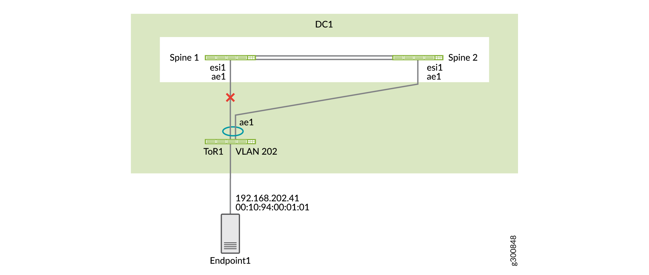 时的拓扑
时的拓扑
验证主干 1 现在正在从主干 2 学习此 MAC 地址,因为主干 1 与 ToR 1 没有直接连接。
user@spine1> show route table bgp.evpn.0 evpn-mac-address 00:10:94:00:01:01
bgp.evpn.0: 76 destinations, 76 routes (76 active, 0 holddown, 0 hidden)
Restart Complete
+ = Active Route, - = Last Active, * = Both

2:192.168.255.12:1::5202::00:10:94:00:01:01/304 MAC/IP
                   *[BGP/170] 00:01:05, localpref 100, from 192.168.255.12
                      AS path: I, validation-state: unverified
                       to 192.168.100.4 via et-0/0/50.0
                    >  to 192.168.100.6 via et-0/0/51.0
主干 1 上的转发表详细信息显示,发往此 MAC 地址的流量将发送到主干 2。
user@spine1> show route forwarding-table destination 00:10:94:00:01:01 extensive
Routing table: default-switch.bridge [Index 6]
Bridging domain: VLAN-202.bridge [Index 6]
VPLS:
Enabled protocols: Bridging, ACKed by all peers,

Destination:  00:10:94:00:01:01/48
  Learn VLAN: 0                        Route type: user
  Route reference: 0                   Route interface-index: 560
  Multicast RPF nh index: 0
  P2mpidx: 0
  IFL generation: 514                  Epoch: 0
  Sequence Number: 0                   Learn Mask: 0x4000000000000000010000000000000000000000
  L2 Flags: control_dyn
  Flags: sent to PFE
  Nexthop:
  Next-hop type: composite             Index: 1724     Reference: 26
  Next-hop type: indirect              Index: 524289   Reference: 3
  Next-hop type: unilist               Index: 524288   Reference: 6
  Nexthop: 192.168.100.4
  Next-hop type: unicast               Index: 1708     Reference: 4
  Next-hop interface: et-0/0/50.0      Weight: 0x0
  Nexthop: 192.168.100.6
  Next-hop type: unicast               Index: 1709     Reference: 4
  Next-hop interface: et-0/0/51.0      Weight: 0x0
验证 VLAN 间服务器连接
分步过程
在主干 1 上,验证两个 MAC 地址是否位于不同的 VLAN 中。
user@spine1> show ethernet-switching table | match 00:10:94:00:11:11
   VLAN-201            00:10:94:00:11:11   DLR      ae1.0
user@spine1> show ethernet-switching table | match 00:10:94:00:01:02
   VLAN-202            00:10:94:00:01:02   DL       ae2.0
在主干 1 上,验证两个端点的 ARP 解析。
user@spine1> show arp no-resolve | match 00:10:94:00:11:11
00:10:94:00:11:11 192.168.201.41  irb.201 [ae1.0]          permanent remote
user@spine1> show arp no-resolve | match 00:10:94:00:01:02
00:10:94:00:01:02 192.168.202.42  irb.202 [ae2.0]          permanent remote
在主干 1 上,检查控制平面学习中的 MAC 地址 00:10:94:00:11:11。您可以看到,该 MAC 地址有 MAC 路由,此 MAC 地址有 MAC/IP 路由。
user@spine1> show route table bgp.evpn.0 evpn-mac-address 00:10:94:00:11:11
bgp.evpn.0: 82 destinations, 82 routes (82 active, 0 holddown, 0 hidden)
Restart Complete
+ = Active Route, - = Last Active, * = Both

2:192.168.255.12:1::5201::00:10:94:00:11:11/304 MAC/IP
                   *[BGP/170] 00:08:43, localpref 100, from 192.168.255.12
                      AS path: I, validation-state: unverified
                       to 192.168.100.4 via et-0/0/50.0
                    >  to 192.168.100.6 via et-0/0/51.0
2:192.168.255.13:1::5201::00:10:94:00:11:11/304 MAC/IP
                   *[EVPN/170] 00:09:01
                       Indirect
2:192.168.255.12:1::5201::00:10:94:00:11:11::192.168.201.41/304 MAC/IP
                   *[BGP/170] 00:08:43, localpref 100, from 192.168.255.12
                      AS path: I, validation-state: unverified
                       to 192.168.100.4 via et-0/0/50.0
                    >  to 192.168.100.6 via et-0/0/51.0
2:192.168.255.13:1::5201::00:10:94:00:11:11::192.168.201.41/304 MAC/IP
                   *[EVPN/170] 00:09:01
                       Indirect
验证这些 MAC 地址的转发表条目。由于主干 1 在本地连接到两个 ToR 交换机,因此流量会在本地从主干 1 切换到相应的 ToR 交换机。
user@spine1> show route forwarding-table destination 00:10:94:00:11:11
Routing table: default-switch.bridge
Bridging domain: VLAN-201.bridge
VPLS:
Enabled protocols: Bridging, ACKed by all peers,
Destination        Type RtRef Next hop           Type Index    NhRef Netif
00:10:94:00:11:11/48 user     0                  ucst     1710     8 ae1.0
user@spine1> show route forwarding-table destination 00:10:94:00:01:02
Routing table: default-switch.bridge
Bridging domain: VLAN-202.bridge
VPLS:
Enabled protocols: Bridging, ACKed by all peers,
Destination        Type RtRef Next hop           Type Index    NhRef Netif
00:10:94:00:01:02/48 user     0                  ucst     1754    10 ae2.0
下一步
您已经为您的第一个数据中心配置并验证了折叠式主干架构。如果需要,请在第二个数据中心的设备上重复配置。
请转到下一页,配置高级安全性并连接您的数据中心。
裂脑状态
如何防止脑裂状态
问题
如果主干交换机之间的链路断开,导致 BGP 对等互连中断,则两台主干交换机均处于活动状态并正在转发。下游聚合以太网接口处于活动状态,并且正在转发。这种情况被称为裂脑状态,可能会导致多个问题。
溶液
要防止发生此问题,请选择一台主干主干交换机作为备用交换机。
我们还建议:
-
在主干交换机之间至少使用两个链路。这样就不太可能主干交换机之间的所有链路中断。
-
对所有服务器进行多宿主。如果其中一台主干交换机上有单宿主服务器,则可能无法访问该服务器。
下一步
您已经为您的第一个数据中心配置并验证了折叠式主干架构。如果需要,请在第二个数据中心的设备上重复配置。
请转到下一页,配置高级安全性并连接您的数据中心。