配置园区交换矩阵 EVPN 多宿主
请按照以下步骤配置 EVPN 多宿主,将核心层和分布层合并到单个交换机中。
瞻博网络 园区交换矩阵 EVPN 多宿主解决方案支持塌缩核心层架构。该架构将核心层和分布层合并到一台交换机中。将这些层合并到单个交换机中,可以将传统的三层分层网络转变为两层网络。该架构还通过提供从接入层到核心层的多宿主功能,消除了对跨园区网络 STP 的需求。
-
EVPN 多宿主拓扑类型仅适用于特定于站点的园区交换矩阵。你不能在组织层面构建它。
-
在 2025 年 5 月更新后在 Mist 云中构建的拓扑中,Mist 会自动检测并报告任何 EVPN 环路和重复的 MAC 地址。这些问题会显示在交换机的“洞察”页面上。
-
EVPN 环路检测 — EVPN-VXLAN 轻量级 PE-客户边缘环路检测有助于检测和断开下游叶至服务器或接入端口上的 LAN 以太网环路。此功能可以检测由各种问题引起的环路,例如交换矩阵组件接线错误或第三方交换机未正确连接到交换矩阵。要使此功能正常工作,交换机必须运行 Junos OS 版本 24.4R1 或更高版本。有关更多信息,请参阅 EVPN-VXLAN 轻型叶到服务器环路检测。
-
重复 MAC 地址检测 — 识别并缓解 EVPN 环境中不同接口或设备之间的 MAC 地址移动(MAC 移动性)所引起的问题。虽然预计会有一些 MAC 移动性(例如,当设备实际移动时),但快速变化可能预示着网络环路或配置错误等问题。有关更多信息,请参阅 配置重复 MAC 地址的环路检测。
-
重复的 VLAN ID — 检测非核心交换机交换矩阵中由于 EVPN 叠加层和底层(例如,在接入点上)上的 VLAN ID 重叠而引起的环路。重叠可能会创建并行的第 2 层转发路径,从而导致桥接环路、广播风暴和服务降级,特别是当接入点流量以隧道传输到 Mist Edge 时。该事件在 “见解”页面上显示为“ 检测到交换矩阵环路)。
-
有关详细的配置示例,请参阅 园区交换矩阵 EVPN 多宿主工作流程。
园区交换矩阵配置最佳实践
- 在交换机模板级别配置 VLAN,并在配置园区交换矩阵时将其导入。模板必须是所有 VLAN 和端口配置文件的单一事实来源,除非交换机或站点级别有特别要求。
- 在接入层,除非明确要求,否则避免使用允许所有 VLAN 的中继端口配置文件。
- 通过园区交换矩阵(而非交换机模板)创建 VRF 和 VRF 网络配置。
- 为每个角色创建端口分配,并根据需要覆盖单个设备上的配置。
- 通过园区交换矩阵工作流程管理 DHCP 中继配置,服务块设备除外。
要配置园区交换矩阵 EVPN 多宿主:
- 从左侧导航菜单中,选择组织>园区交换矩阵。
- 从页面标题旁边的站点下拉列表中,选择要在其中构建园区交换矩阵的站点。
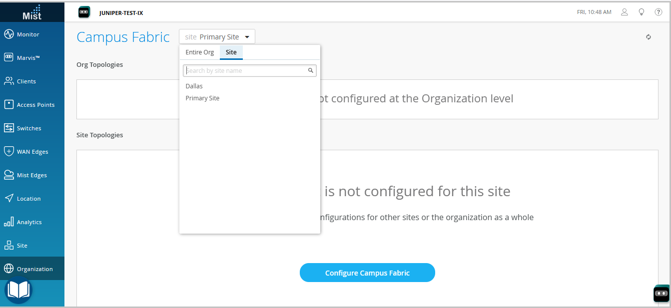
- 单击相关的选项。点击:
-
配置 园区交换矩阵 按钮(如果站点没有关联园区交换矩阵配置,则显示)。
-
创建 园区交换矩阵按钮 (如果站点已至少有一个园区交换矩阵配置关联,则显示)。
将显示拓 扑 选项卡。 -
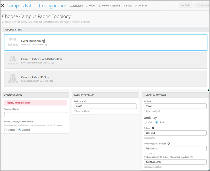
- 选择拓扑类型:EVPN 多宿主。
- 在拓扑选项卡上配置其余设置,如下所述:
注意:
除非这些设置与连接到园区交换矩阵的任何网络冲突,否则建议使用此屏幕上的默认设置。每一层之间的点对点链路利用 /31 寻址来保存地址。
- 在 CONFIGURATION 部分中,配置以下内容:
-
拓扑名称 - 输入拓扑的名称。
-
虚拟网关 v4 MAC 地址 — 启用此选项以支持 WLAN 上的访客门户重定向。时,Mist 将向每个第 3 层 (L3) 虚拟网关(每个网络)提供一个唯一的 MAC 地址。默认情况下禁用。
-
- (如果您选择不使用默认设置)在“叠加设置”部分中,输入以下内容:
-
BGP 本地 AS — 表示 Mist 自动分配给每个设备的专用 BGP AS 编号的起点。可以使用适合部署的任何专用 BGP AS 编号范围。Mist 配置了路由策略,以便仅在交换矩阵的底层中交换环路 IP 地址。
-
- (如果您选择不使用默认设置)在底层设置部分中,配置以下内容:
-
AS 基数 — AS 基数。默认值为 65001。
-
底层 — 选择底层的互联网协议版本。选项为 IPv4 和 IPv6。
-
子网 — Mist 用于设备之间点对点链路的 IP 地址范围。可以使用适合部署的范围。Mist 将此子网分解为每个链路的 /31 个子网寻址。您可以修改此数字以适应特定的部署规模。例如,/24 网络将提供多达 128 个点对点 /31 子网。
-
IPv6 环路接口 — 指定一个 IPv6 环路接口子网,用于在交换矩阵中的每台设备上自动配置 IPv6 环路接口。
-
自动路由器 ID 子网/环路接口 — Mist 使用此子网自动为交换矩阵中的每个设备分配路由器 ID(包括接入设备,无论其是否配置了 EVPN)。路由器 ID 是用于设备之间叠加对等的环路接口 (lo0.0)。对于新拓扑,此字段会自动填充默认子网值 (172.16.254.0/23),您可以对其进行修改。编辑现有拓扑时,此字段不会填充任何默认值。在部署 BGP 等路由协议时,路由器 ID 用作标识符。将交换机添加到塌缩核心层后,单击交换机图标以查看关联的路由器 ID。
对于 IPv4 部署,您可以选择禁用自动路由器 ID 分配并手动配置路由器 ID。为此,请将此字段留空,然后从 节点 选项卡手动配置路由器 ID。
对于 IPv4 部署,您还可以在交换机配置页面(交换机 > 交换机名称)上路由磁贴上的路由器 ID 字段中手动配置环路接口,以覆盖自动分配的路由器 ID。但是,如果事后修改园区交换矩阵配置,Mist 会再次自动分配路由器 ID,从而替换手动配置的环路接口。
-
- 在 CONFIGURATION 部分中,配置以下内容:
- 单击继续以转到节点选项卡,您可以在其中选择构成园区交换矩阵部署一部分的设备。
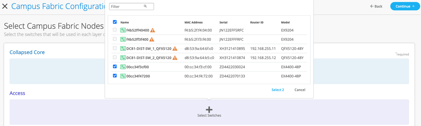
- 将 交换机添加到塌缩核心层和接入层。
在创建园区交换矩阵之前,建议您验证交换机清单中是否存在每台设备。
要添加交换机:
- 单击选择交换机。
- 选择要添加到园区交换矩阵的交换机。
- 单击“选择”。
注意:如果将拓扑选项卡上的自动路由器 ID 子网/环路接口字段留空,则必须手动为交换机配置路由器 ID。为此,请选择已添加到交换矩阵的交换机,并在右侧显示的窗格中配置路由器 ID。仅 IPv4 部署支持手动路由器 ID 分配。
- 选择交换机后,单击“继续”转到“网络设置”选项卡,您可以在其中配置网络。
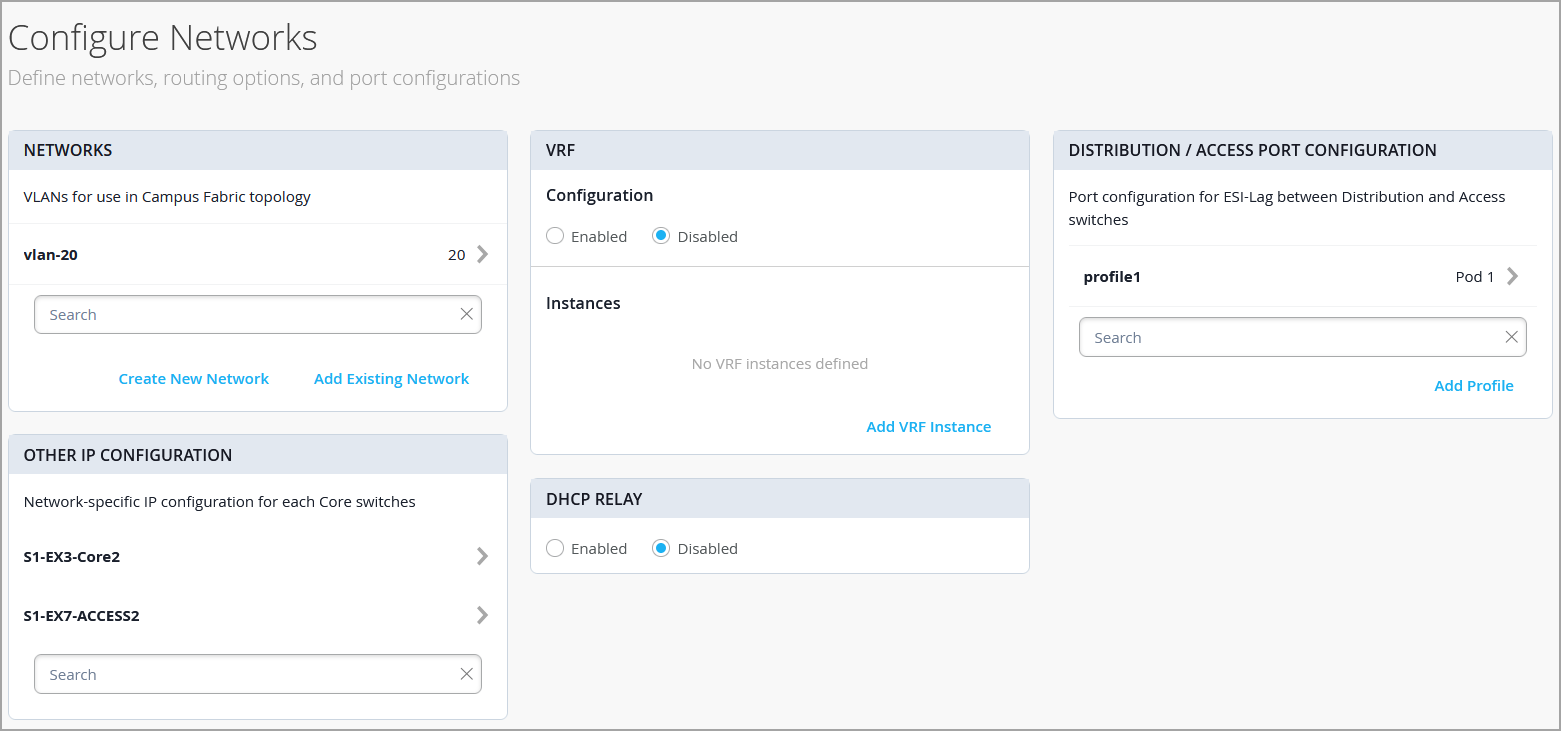
- 配置网络设置,如下所述:
- 在 NETWORKS 磁贴上,将网络或 VLAN 添加到配置中。您可以创建新网络,也可以从组织>交换机模板页面上定义的交换机模板导入网络。
要添加新 VLAN,请单击 Create New Network 并配置 VLAN。这些设置包括名称、VLAN ID 和子网。您可以为子网指定 IPv4 或 IPv6 地址。
要从模板导入 VLAN,请执行以下操作:
-
单击 添加现有网络。
-
从 模板 下拉列表中选择交换机模板,以查看该模板中可用的 VLAN。
-
从显示的列表中选择所需的 VLAN,然后单击 ✓ 标记。
VLAN 映射到虚拟网络标识符 (VNI)。您可以选择将 VLAN 映射到虚拟路由和转发 (VRF) 实例,以在逻辑上分离流量。
-
- 查看“其他 IP 配置”磁贴中的设置。在“网络”部分中指定网络后,此部分会自动填充设置。
- (可选)配置 VRF 实例。在基于分段的园区交换矩阵架构中应用 5 类(IP 前缀)策略时,建议使用 VRF。默认情况下,Mist 会将所有 VLAN 置于默认 VRF 中。VRF 选项允许您根据流量隔离要求,将公共 VLAN 分组到相同的 VRF 中或单独的 VRF 中。每个 VRF 中的所有 VLAN 彼此之间以及与其他外部网络资源之间都有完全的连接。一个常见的用例是将访客无线流量与大多数企业域隔离(互联网连接除外)。默认情况下,园区交换矩阵在 VRF 之间提供完全隔离,迫使 VRF 间通信必须遍历防火墙。如果需要 VRF 间通信,则需要为 VRF 添加额外的路由。额外路由可以是指示园区交换矩阵使用外部路由器的默认路由。它还可以用作防火墙,以实现进一步的安全检查或路由功能。
要创建 VRF:
-
在 VRF 磁贴上,单击“ 添加 VRF 实例” 并指定设置。这些设置包括 VRF 的名称以及要与 VRF 关联的网络。
-
要添加其他路由,请单击“新建 VRF 实例”页面上的“添加额外路由”链接,然后指定路由。您可以指定 IPv4 或 IPv6 地址。
-
- 在“核心/接入端口配置”磁贴上,完成塌缩核心层与接入交换机之间的 ESI-LAG 端口配置。这些设置包括名称和其他端口配置元素。默认情况下,此配置包括在同一页面的“网络”磁贴上添加的网络。如果要删除或修改设置,请单击“显示高级”并配置设置。使用屏幕上的提示配置端口配置文件设置。
- 在 DHCP 中继磁贴上,配置 DHCP 中继设置。您有以下选项:
-
启用 — 在园区交换矩阵中所有支持 IRB 的设备上配置 DHCP 中继。此选项允许您在所选网络上启用 DHCP 中继。只要该网络列在同一页面的“网络”选项卡上,网络就会填充在 DHCP 中继磁贴中。
-
已禁用 — 禁用园区交换矩阵中设备上的 DHCP 中继。选择此选项后,所有支持 IRB 的设备上的 DHCP 中继都将被禁用。您应仔细选择此选项,因为这将移除“交换机详细信息”页面上本地定义的 DHCP 中继。
-
无 — 当园区交换矩阵拓扑在 DHCP 中继配置方面具有多种设备时,会自动选择此选项;也就是说,某些设备启用了 DHCP 中继,有些设备禁用了 DHCP 中继,有些设备未定义。对于在单个交换机上本地定义了 DHCP 中继的所有园区交换矩阵拓扑,此选项将可见。
如果要移除所有本地定义的 DHCP 中继网络,请选择 已启用, 然后选择 移除所有现有设备级 DHCP 网络。您可以通过集中园区交换矩阵工作流程中的任何配置更改来简化 DHCP 中继部署。
如果在园区交换矩阵配置中启用 DHCP 中继,则会在交换矩阵中所有 IRB 定义的设备上启用,而在其余设备上禁用。例如,在 EVPN 多宿主拓扑中,DHCP 中继在塌缩核心层设备上启用,在其余设备上禁用。
-
- 在 NETWORKS 磁贴上,将网络或 VLAN 添加到配置中。您可以创建新网络,也可以从组织>交换机模板页面上定义的交换机模板导入网络。
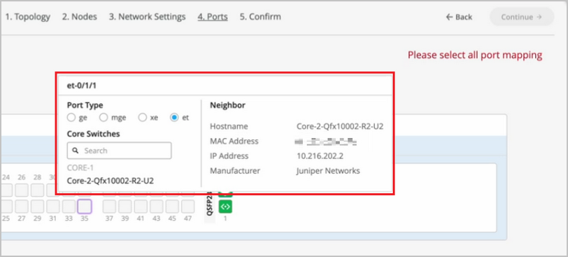
- 单击继续以转到 Ports 选项卡,您可以在其中配置端口并在核心、分布和接入层交换机之间创建连接。
- 按 如下方式配置塌缩核心层中的交换机端口:
- 在 Collapsed Core 部分中选择一个交换机以打开交换机端口面板。
- 从交换机的端口面板中,选择要配置的端口。
- 指定端口类型(例如,
ge或xe)。 - 选择:
-
链接到塌缩核心层 ,以将端口连接到核心交换机。
在塌缩核心层中,您可以将每个交换机连接到每个其他交换机上,形成全网状拓扑。全网状拓扑结构为 EVPN 多宿主园区交换矩阵提供了更高的弹性,即使一台设备发生故障,也能确保网络持续运行。
-
链接到接入 ,以将端口连接到接入交换机。
-
- 选择链路应终止的核心或接入交换机(基于上一步中的选择)。您需要配置成为园区交换矩阵一部分的所有端口。
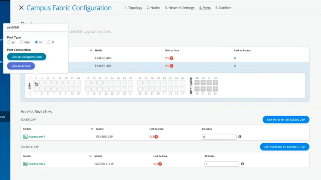 要在接入层中配置交换机端口,请执行以下操作:
- 在 Access 部分中选择交换机以打开交换机端口面板。
- 从交换机的端口面板中,选择要配置的端口。
- 指定端口类型(例如,
ge或xe)。如果接入层使用虚拟机箱 (VC),您可以在 Primary 和 Backup 选项卡上配置端口。
对于接入交换机,仅选择那些应用于与分布式交换机互连的接口。系统通过 AE 索引选项将所有接口捆绑到单个以太网捆绑包中。您可以为接入设备指定 AE 索引值。
如果要查看特定端口的配置和状态信息,请将鼠标悬停在端口面板 UI 中代表该端口的编号框上。
- 单击“继续”转到“确认”选项卡。
- 单击每个交换机图标,查看并验证配置。
- 验证配置后,单击“应用更改”>“确认”。
此步骤会将园区交换矩阵配置保存到 Mist 云,并将其应用到交换机。如果交换机处于脱机状态,则在交换机下次联机时将对其应用配置。交换机可能需要长达 10 分钟才能完成配置。
- 单击关闭园区交换矩阵配置。
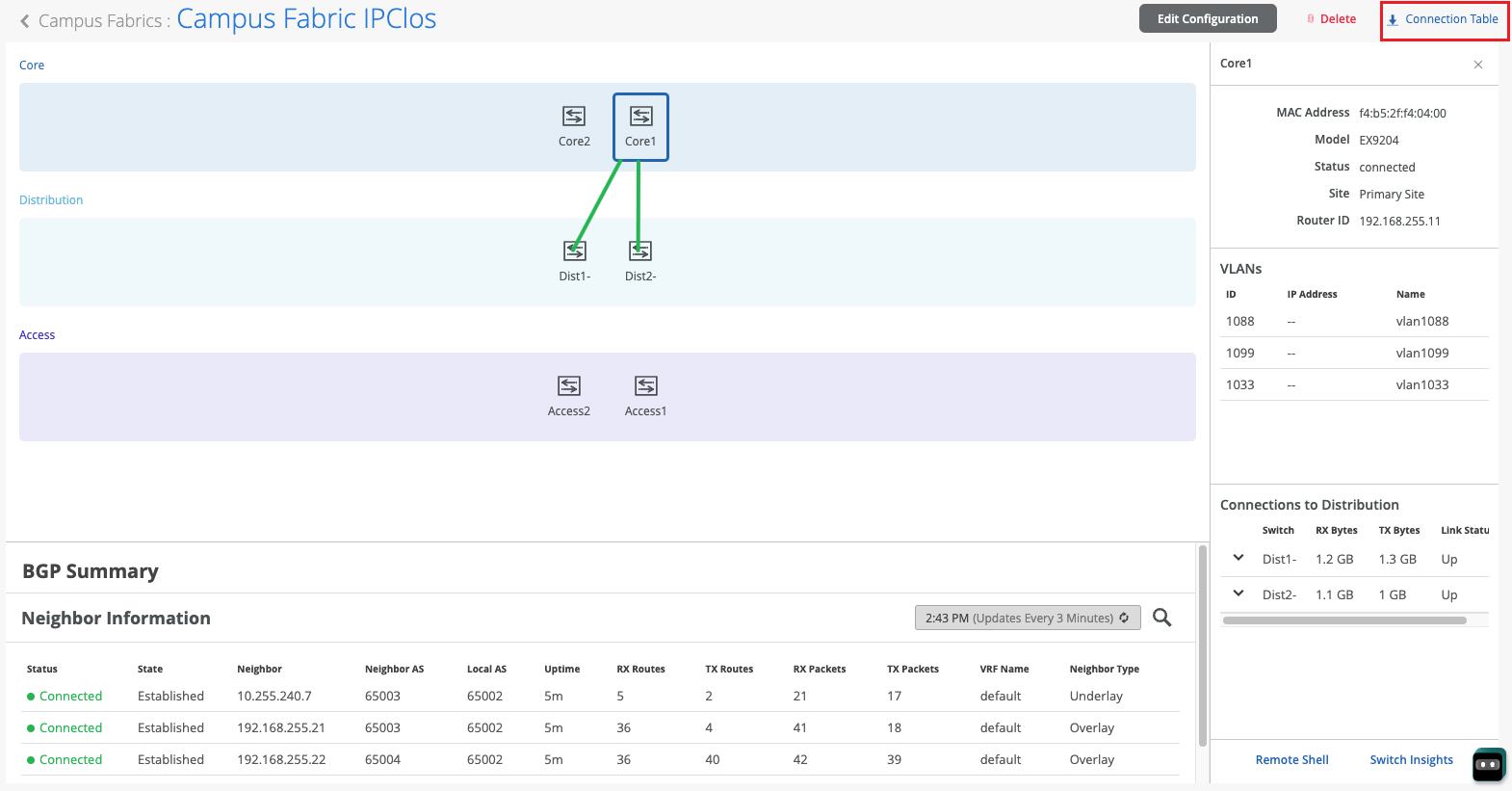
在 Mist 构建园区交换矩阵后,或者在构建交换矩阵时,您可以下载连接表。连接表表示园区交换矩阵的物理布局。您可以使用此表来验证参与物理园区交换矩阵构建的设备的所有交换机互连。单击 连接表 下载(.csv格式)。
- 验证园区交换矩阵配置。要进行验证,请按照园区交换矩阵 EVPN 多宿主工作流程中的验证部分中列出的步骤操作。
Hello and welcome to this edition of Wired Assurance. My name is Rohan Chada and today I'll be talking about building an EVPN week stand campus fabric in just four steps. Today we're going to talk about the deployment of EVPN multi homing topology. I'll walk you through the different steps that are required and I can promise you none of those require any CLI configuration.
Everything will be done through the UI and it'll be as simple as you can expect it to be. So let's just jump right into it and talk about EV Pin Multi Hamming. Before we jump into building the EV Pin Multi Hamming topology, let's understand the building blocks of it from a device perspective. Today as you can see, we're going to be using 2 core devices and two access devices.
The EVPN Multi Hamming topology can support up to 4 core devices, a minimum of two and a maximum of four and as many access devices as you'd like. But for this purposes of this video, we'll be using 2 core devices and two access devices. So to begin with, we click on organization and we under the wire tab we see Campus fabric. So as we click on Campus fabric, we can see that we are inside the site EVPN campus primary one and there is no campus fabric configured at this time.
And that's exactly where we'll begin. Click on configure campus fabric and we see that there are three topologies that are presented to us. EVPN multi homing which is collapse code with ESI lag, campus fabric Code distribution which is EVPN code distribution with ESI lag and canvas fabric IP cloth. What you see on the left side of each of these three names is a small diagram that basically depicts the topology that this this entails.
So you basically have above the line that you see the horizontal line in the diagram on each of these topologies. Above the line is where your your evpn vxlan construct exists. And what I mean by that is that's where those devices are, the devices that run Evpn vxlan configuration. Anything below the horizontal line are just pure access devices layer to they can be, they have to be non evpn VXLAN capable devices.
So once you've selected the EVPN multi homing we see that it's a collapsed core and what that means is that two or three layers of EVPN configuration is collapsed into just one layer. So we'll jump right in there by giving it a topology name. We're going to go ahead and call it evpn image. There are two settings that you have to provide on the initial page and that's for the overlay and the underlay settings.
For overlay we use ibgp today and for underlay we use ebgp. The default values will be presented to you, there is no reason to change it if there isn't a purpose behind it. And 65,000 is the local AS and 65,001 is the AS base to begin with for the underlay ebgp. And then we'll increment sequentially on a device spaces starting with 65001.
The loopback prefix as you can see is the the prefix that's used to assign to all the interfaces, all the loopback interfaces on all the devices. These interfaces are used to peer with every other VTAP in the campus fabric. And then last is the subnet, which is again a default value provided that can be changed by the user. This subnet is used to connect the underlying physical interfaces between the campus fabric.
Let's jump right into the next step and click on Continue. At this step we'll be selecting the Campus fabric nodes. In this Campus fabric configuration we'll be selecting 2 Campus course and I'll select Code one and Code 3 for this demo. And as you can see in this nice drop down, you have all the information provided to you and that includes the model as well as the Mac address so you don't have to go back and forth between different pages of the UI.
Every information is provided right here. For the access devices, I'll be picking switch one and switch two. My core devices are EX 465048 wise that are EVPN capable. My access devices are EX 2300 and 4300 that do not understand EVPN.
Hence I am putting these in an access layer. The platform support on a topology basis is on the on the website and we've listed every platform that's supported on a per layer basis. So once you've selected this topology, we know that there are two core devices, 2 access devices. I can click on these core devices and I can see that the basic information about core one I see there is a router ID assigned.
This router ID is assigned as needed for the loop back interface. As I mentioned earlier, that's used for peering between the two core devices. In case of a collapsed core, the two core devices will act as the as the two vtips that basically they will be forming A VXLAN tunnel between each other. The access, which is on the other hand do not necessarily need a router ID, but we've provided them for consistency's sake.
They do not need it, but let's go ahead with that. Step three is basically configuring networks. So networks are basically of Vlans. So we'll go ahead and start creating some new networks here.
I'm going to be assigning some generic names here and I'll call it image vlan 10 and S and vlan ID 10 and I'll give it the subnet 190 to one 6810.0 slash 24 and I'll give it a virtual gateway for 190 to 168 dot 10.1. Now providing this subnet is. This is the only I would say.
This is the second step wherein you'll be providing us a subnet. The IP addressing for the IRB slash SVI interfaces or any IP addressing in the underlying physical interfaces in our fabric is taken care by missed Wire Assurance Campus Fabric. As a user and administrator, you don't have to worry about it. So once you've provided us a subnet, we'll take care of it.
So this virtual gateway will essentially be used for as a common address between the two core devices. So any underlying device, for example an access switch or any any device connected to the access switch will have its gateway as 190 to 168 or 10.1 which will be advertised via avpn and that's why we come in here and manually define it. So as you can see, I created a VLAN, VLAN 10 and voila, we see two IP addresses that have already been chosen to be assigned for the corresponding IRB slash SVI interfaces that will be assigned to code one and code 3 for VLAN 10.
Let's go ahead and create another one and we'll call it image VLAN 20. But in this case I'm not going to assign a subnet or virtual git net because I want to route for this particular VLAN. I want to route on the the the firewall of the campus fabric. So my the two core devices that I have will be connected dual home to a firewall and I want the routing to happen for this particular VLAN on the firewall.
So I'm going to skip this and this is basically a bridged overlay design wherein we'll assign the VNI to the corresponding VLAN 20, but we will not be configuring A subnet or a gateway on the 2 core devices. This is one way of creating a VLAN. The other way of adding a VLAN to the campus fabric is if you have existing network on the sites already. So we'll click on existing network and what we see is that there is a common VLAN that we already created earlier before we started this demo on an entire site.
So using the site configuration here, I created a VLAN called site wide VLAN with a VLAN ID of 100 and that's it. And what that did was all the devices in that site inherited the site wide VLAN. So I'm going to take site wide VLAN and I'm going to add that. So now I'm told that there is a virtual gateway that is required.
OK, there is a virtual gateway required. So we'll go ahead and add the virtual gateway. The subnet basically was inherited from the the site configuration where I had created VLAN printer. So I'm being told that the provided gateway is already used.
OK, so here we have 3 Vlans and as we already see that for two of them the static IP addresses have already been defined. For VLAN 10 there are two IP addresses, code one and code 3. Similarly for site VLAN 100, we have two IP addresses, one each for core one and core 3. And as we already know VLAN 20 is a doesn't have a virtual gateway on the collapse core, so we do not have a gateway for that.
Now let's jump into VRF and understand this is virtual routing and forwarding wherein you can create separate routing instances. You can basically increase the security in your network by segregating the Vlans in different routing instances. A different routing instance basically means that there is a different routing table on a per VLAN basis or however many Vlans you would like in that particular VRF. So we'll go and assign this name vrf one and then we'll we'll add image vlan 10 to vrf one if if there is a need.
I can always add extra routes within the VRF as well and that is an option. You go ahead and another VRF called VRF 2 and I'll use site by vlan for this particular VRF 2. The last step on this page is to basically configure the core access port configuration. This is the port configuration towards the access switches from the collapse code as it if you read the description it says this is the ESL configuration.
So let's just assign it a name and let's call it Yesi LAG, any name of the book, but Yesi Haffen LAG is what I've assigned. We presume that all the Vlans and networks that you've defined here are going to be a part of the ESI LAG configuration, and so we automatically add them to the trunk networks. You can come in here and manually change any settings that you would like. If you would like a smaller MTU or if you would like to manipulate the MTU size here to your environment needs, you can do that.
You can enable storm control. You can also enable Poe if that's a requirement, change the speed, duplex, add native VLAN. All of that is an option that we've provided. This is the last and final step and what we see here is there are different port panels.
These port panels are on a platform basis. For the purposes of this video, we are using EX4650 and two other platforms. So we'll show you the appropriate port panels as needed whenever any platform other than these are used. So let's jump right into it and let's let I'll go ahead and I'll configure these interfaces quickly.
So what I've done at this point is I've connected all the two collapsed core devices with the other two access devices. Basically the requirement is that there should be two interfaces connected to each other between the two core devices. Evpn multi Homing has that requirement for redundancy and then core one needs to connect to both access switch one and Access switch 2. Similarly code 3 needs to connect to both access switch one and access Switch 2.
So once those interfaces have been have been connected here you've told the missed UI that these are the interfaces. We can proceed and we can click on continue. This is the last step wherein you confirm that the topology changes that you want are there and if you click on code 1, we can see that on the right. We see a lot of information about everything that we've done so far.
We see the model, we see the router ID, we see the Vlans that we wanted in the campus fabric. Along with the Vlans we also see the IP addresses. I see that there are two IP addresses and three Vlans. One of them is and doesn't have an IP address and that is basically a bridge overlay design as I mentioned earlier.
We also see the connections by the way. I can see and I can verify here the connections connections to collapsed core or three and access switch one and access switch two at any point in this entire step. If you'd like to access the remote shell, we've provided you that option as well. So before you hit apply changes, if you'd like to log into your device you can do that here.
You can click on remote shell and pop up window will open for you and at this point you can you can look at your configuration. You can look at how your devices are connected. I see here that my devices are connected or one connects to two core 3 interfaces and core one has a connection to switch to and switch one as well. So a a little handy tool here where you can verify by logging into the device.
Let's click apply changes and confirm. At this time, what has happened is that the configuration that we decided to push to the devices is being pushed and is being committed to the junuper devices and right after that's committed, BGP Underlay as well as Overlay will be provisioned. Once BGP Underlay is provisioned, overlay and the VX LAN tunnels will come up, the VX LAN tunnel will be two way between collapsed Core one and collapsed Core 2. Let's just jump right into the switches while this configuration is happening.
We look at what's the scenario and the switches and the configuration that we pushed under the hood. Remember, everything that we did so far was based on UI. We did not touch the CLI. We did not make any CLI changes manually.
You did not have to define the EVPN configuration or the BGP configuration or the underlying physical connectivity. This is the value of Missed Wire Assurance Campus Fabric. Let's click on Utilities and click on Download JS Config. We see that configuration file has been downloaded.
This is a. This is a handy tool. What this does is it enables us to verify the configuration. All of us have been used to configuring things while the CLI and so it is very important that we verify that if you're doing this for the first time that everything that you want in the configuration should be there.
You could be a Greenfield environment or or a brownfield environment. You should be able to verify your configuration. So let's dive right into it. Let's look at this.
So as we can see, the first thing I see is I see some BGP configuration here. That's very important. We see the underlay BGP configuration here between the two core devices. There are two peers here on 2 interfaces.
We see the overlay configuration here since there's only one peer for core one and that is core three. There is only one neighbor. We see some EVPN configuration here, right? We also see the ESI LAG configuration here that was pushed by Campus Fabric.
None of that required us to push anything through CLI. We see 22 LAG interfaces AE0 and AE1AE0. It's towards switch one and AE three is towards switch two. We see the IRB configuration as we discussed earlier.
IRB 10 is the the first VLAN that we defined with a gateway and IRB 100 is the third one that was inherited from the site wide template. We also see the VRF configuration here. So as we can see, there's VRF one configuration that has one VLAN IRB .10. We also have type 5 routes as a part of it.
We also see VRF 2 configuration in this VRF 2 configuration, what we see is IRP 100. The second, I'm sorry, the third VLAN that we chose is also there. And then if you look at the configuration here, we see all three Vlans, even the VLAN, even the VLAN that we made bridged overlay is a part of the configuration has a VNI. So we can go ahead and we can assign the gateway for this particular VLAN on either the router of the campus fabric or the firewall based on your environment.
So now that we've looked at the configuration, let's look at how our EVPN campus fabric is doing and what do the EVPN insights tell us. So the EVPN insights, it's basically a pretty layer on top of the campus fabric that tells you about a few green and red links. And those green and red links are not not just the the interface status. They tell you some good information about your peering in the network.
So we looked at there are a few green links. We see that the status is up, but we see these triangles. And these triangles are not, they do not look great. So when I hover over this topology, I am being told that the selected port is not connected to the correct switchboard in the campus traffic topology.
What that basically means is that the the the back end of the campus fabric knows that the core one to core 3 port that I've selected is not the right port and instead it is something else. It is smart enough to understand that there was another port that should have been connected, but I have connected the wrong the wrong port and that is absolutely right. So I'm going to jump right into the campus fabric and change that quickly for you guys. So I'll click on edit configuration and go right to the last step and I'll change this zero to 1 and we'll hit continue and we'll apply changes and save them while the provisioning takes a while.
I'll be right back in a minute. So, so we're back. So as we can see our pretty green lines are back. What and what that means is that we've you corrected the interface that was not correct in the right way.
Campus Fabric was smart enough to let us know that the interfaces that were connected between code one and code three were not right. As you can see, I had 000 earlier and I switched that over to 001 and after doing that my BGP neighborship came back. And then here we can see if I click on any device the statistics between the two devices. We can also see, as I mentioned earlier, the Vlans and the IP addresses.
Thank you. This concludes our campus fabric demo today. I'll summarize all the things that we did today in this last 2025 minute session. So we built a campus fabric using the Mist UI.
None of those steps included anything to do on the CLI. We built a campus fabric in four steps wherein we as a step one, we selected the kind of topology that the user would want. As a second step, we chose the campus fabric nodes that will participate in the campus fabric. The third step was to provide us the networks that will be participating in the in the campus fabric.
And the last and final step was the connectivity of the devices itself. It's as simple as that.