本页内容
NVIDIA 配置
NVIDIA® ConnectX® 系列网络接口卡 (NIC) 提供先进的硬件卸载和加速功能,速度高达 400G,支持以太网和 Infiniband 协议。
进行更改时,请务必参考官方制造商文档。本节提供基于 AI JVD 实验室测试的一些指南。
将 NVIDIA ConnectX NIC 从 Infiniband 转换为以太网
默认情况下,NVIDIA ConnectX NIC 设置为作为 Infiniband 接口运行,并且必须使用 mlxconfig 工具转换为以太网。
1) 使用 sudo mst status 检查 ConnectX NIC 的状态。
-
user@A100-01:/dev/mst$ sudo mst -h

Usage:

    /usr/bin/mst {start|stop|status|remote|server|restart|save|load|rm|add|help|version|gearbox|cable} Type "/usr/bin/mst help" for detailed help

user@A100-01:/dev/mst$ sudo mst status | egrep "module|load"

MST modules:

    MST PCI module loaded

    MST PCI configuration module loaded
如有必要,启动 mst 服务或加载 mst 模块。
示例:
-
user@H100-01:~$ sudo mst start

Starting MST (Mellanox Software Tools) driver set

Loading MST PCI module - Success

[warn] mst_pciconf is already loaded, skipping

Create devices

Unloading MST PCI module (unused) - Success

user@A100-01:~/scripts$ sudo mst status

MST modules:

------------

    MST PCI module is not loaded

    MST PCI configuration module loaded
modprobe
mst_pci.
-
user@A100-01:/dev/mst$ sudo modprobe mst_pci

user@A100-01:/dev/mst$ sudo mst status

MST modules:

------------

    MST PCI module loaded

    MST PCI configuration module loaded
2) 确定要转换的接口,
此 sudo mst status -v 命令将提供系统上检测到的 Mellanox 设备(ConnectX-6 和 ConnectX-7 NIC)的列表,以及它们的类型、Mellanox 设备名称、PCI 地址、RDMA 接口名称、NET 接口名称和 NUMA ID,如下例所示:
-
user@A100-01:/dev/mst$ sudo mst status -v

MST modules:

------------

    MST PCI module loaded

    MST PCI configuration module loaded

PCI devices:

------------

DEVICE_TYPE         MST                         PCI      RDMA     NET                NUMA

ConnectX7(rev:0)    /dev/mst/mt4129_pciconf7.1  cb:00.1  mlx5_13  net-eth13          1

ConnectX7(rev:0)    /dev/mst/mt4129_pciconf7    cb:00.0  mlx5_12  net-gpu6_eth       1

ConnectX7(rev:0)    /dev/mst/mt4129_pciconf6.1  c8:00.1  mlx5_11  net-enp200s0f1np1  1

ConnectX7(rev:0)    /dev/mst/mt4129_pciconf6    c8:00.0  mlx5_10  net-gpu7_eth       1

ConnectX7(rev:0)    /dev/mst/mt4129_pciconf5.1  8e:00.1  mlx5_19  net-eth19          1

ConnectX7(rev:0)    /dev/mst/mt4129_pciconf5    8e:00.0  mlx5_18  net-gpu5_eth       1

ConnectX7(rev:0)    /dev/mst/mt4129_pciconf4.1  8b:00.1  mlx5_17  net-enp139s0f1np1  1

ConnectX7(rev:0)    /dev/mst/mt4129_pciconf4    8b:00.0  mlx5_1         net-gpu4_eth       1

ConnectX7(rev:0)    /dev/mst/mt4129_pciconf3.1  52:00.1  mlx5_3         net-enp82s0f1np1   0

ConnectX7(rev:0)    /dev/mst/mt4129_pciconf3    52:00.0  mlx5_2         net-gpu3_eth       0

ConnectX7(rev:0)    /dev/mst/mt4129_pciconf2.1  51:00.1  mlx5_1   net-enp81s0f1np1   0

ConnectX7(rev:0)    /dev/mst/mt4129_pciconf2    51:00.0  mlx5_0   net-gpu2_eth       0

ConnectX7(rev:0)    /dev/mst/mt4129_pciconf1.1  11:00.1  mlx5_9   net-enp17s0f1np1   0

ConnectX7(rev:0)    /dev/mst/mt4129_pciconf1    11:00.0  mlx5_8   net-gpu1_eth       0

ConnectX7(rev:0)    /dev/mst/mt4129_pciconf0.1  0e:00.1  mlx5_7   net-enp14s0f1np1   0

ConnectX7(rev:0)    /dev/mst/mt4129_pciconf0    0e:00.0  mlx5_6   net-gpu0_eth       0

ConnectX6DX(rev:0)  /dev/mst/mt4125_pciconf0.1  2c:00.1  mlx5_5   net-enp44s0f1np1   0

ConnectX6DX(rev:0)  /dev/mst/mt4125_pciconf0    2c:00.0  mlx5_4   net-mgmt_eth       0

ConnectX6(rev:0)    /dev/mst/mt4123_pciconf0.1  a9:00.1  mlx5_15  net-eth15          1

ConnectX6(rev:0)    /dev/mst/mt4123_pciconf0    a9:00.0  mlx5_14  net-weka_eth       1

Cable devices:

---------------

mt4129_pciconf7_cable_0

mt4129_pciconf6_cable_0

mt4129_pciconf5_cable_0

mt4129_pciconf4_cable_0

mt4129_pciconf3_cable_0

mt4129_pciconf2_cable_0

mt4129_pciconf1_cable_0

mt4129_pciconf0_cable_0

mt4125_pciconf0_cable_0

mt4123_pciconf0_cable_0
对于列表中的第一个接口,您可以识别以下内容:
- 类型 = ConnectX7(rev:0)
- Mellanox 设备名称 = mt4129_pciconf7 (/dev/mst/mt4129_pciconf7)
- PCI 地址 = cb:00.0
- RDMA 接口名称 = mlx5_12
- NET 接口名称 = net-gpu6_eth
- NUMA = 1
请注意,对于某些接口,名称遵循标准 Linux 接口命名方案(例如 net-enp14s0f1np1),而其他接口则不然(例如 net-gpu0_eth)。不遵循标准的接口名称是用户定义的名称,以便于识别。这意味着 /etc/netplan/ 中的默认名称已更改。我们将在本节后面展示如何执行此作的示例。
3) 识别给定接口正在运行什么模式
mlxconfig -d <device> 查询
示例:
-
user@A100-01:~/scripts$ sudo mlxconfig -d /dev/mst/mt4129_pciconf7query | grep LINK_TYPE

        LINK_TYPE_P1     IB(1)

        LINK_TYPE_P2     IB(1)  <= indicates link is operating in Infiniband mode
请注意,您需要使用 Mellanox 设备名称,包括路径 (/dev/mst/mt4129_pciconf7)。
此外,LINK_TYPE_P1 和 LINK_TYPE_P2 指的是双端口 Mellanox 适配器中的两个物理端口。
4) 如果接口在 Infiniband 模式下运行,您可以使用以下命令更改以太网模式的模式
mlxconfig -d <device> set [LINK_TYPE_P1=<link_type>] [LINK_TYPE_P2=<link_type>]
示例
-
user@A100-01:~/scripts$ sudo mlxconfig -d /dev/mst/mt4129_pciconf7 set LINK_TYPE_P1=2 LINK_TYPE_P2=2

Device #1:

----------

Device type:        ConnectX7

Name:               MCX755106AS-HEA_Ax

Description:        NVIDIA ConnectX-7 HHHL Adapter Card; 200GbE (default mode) / NDR200 IB; Dual-port QSFP112; PCIe 5.0 x16 with x16 PCIe extension option; Crypto Disabled; Secure Boot Enabled

Device:             /dev/mst/mt4129_pciconf7

Configurations:                                          Next Boot       New

        LINK_TYPE_P1                                ETH(2)               ETH(2)

        LINK_TYPE_P2                                ETH(2)               ETH(2)

 Apply new Configuration? (y/n) [n] : y

Applying... Done!

-I- Please reboot machine to load new configurations.

user@A100-01:~/scripts$ sudo mlxconfig -d /dev/mst/mt4129_pciconf7query | grep LINK_TYPE

        LINK_TYPE_P1     ETH(2)

        LINK_TYPE_P2     ETH(2)   <= indicates link is operating in Ethernet mode
同样,请注意您需要使用 Mellanox 设备名称,包括路径 (/dev/mst/mt4129_pciconf7)。
要检查接口的状态,您可以使用 mlxlink:
-
user@A100-01:/dev/mst$ sudo mlxlink -d /dev/mst/mt4129_pciconf4

Operational Info

----------------

State                              : Active

Physical state                     : LinkUp

Speed                              : 200G

Width                              : 4x

FEC                                : Standard_RS-FEC - (544,514)

Loopback Mode                      : No Loopback

Auto Negotiation                   : ON

Supported Info

--------------

Enabled Link Speed (Ext.)          : 0x00003ff2 (200G_2X,200G_4X,100G_1X,100G_2X,100G_4X,50G_1X,50G_2X,40G,25G,10G,1G)

Supported Cable Speed (Ext.)       : 0x000017f2 (200G_4X,100G_2X,100G_4X,50G_1X,50G_2X,40G,25G,10G,1G)

Troubleshooting Info

--------------------

Status Opcode                      : 0

Group Opcode                       : N/A

Recommendation                     : No issue was observed

Tool Information

----------------

Firmware Version                   : 28.39.2048

amBER Version                      : 2.22

MFT Version                        : mft 4.26.0-93
更多详情可以参考:
识别 NIC 和 GPU 映射并分配适当的接口名称
NIC 可随时由任何 GPU 使用;给定的 GPU 只能使用特定的 NIC 卡与外部世界通信,这并没有硬编码。但是,GPU 和 NIC 之间存在首选的通信路径,在某些情况下可以将其视为它们之间的 1:1 对应关系。这将在以下步骤中显示。
NCCL(NVIDIA 集体通信库)将选择从给定 GPU 到其中一个 NIC 的最佳连接路径。
要确定 NCCL 选择的路径以及 GPU 和 NIC 之间的最佳路径是什么,请执行以下步骤:
使用 nvidia-smi topo -m 命令(显示有关系统的拓扑信息)来识别 GPU 和 NIC 之间的连接类型:
示例:
- DGX H100:
图 92.Nvidia H100 系统管理接口 (SMI) 系统拓扑信息 
基于我们的研究:
表 26:每种连接类型的性能
| 连接类型 | 描述 | 性能 |
| 像素 | PCIe 安装在同一台交换机上 | 良好 |
| PXB | PCIe 可通过多个交换机,但不能通过主机桥接 | 良好 |
| PHB | PCIe 交换机并通过同一 NUMA 上的主机网桥 - 使用 CPU | 确定 |
| 节点 | PCIe 交换机以及同一 NUMA 上的多个主机网桥 | 差 |
| 系统 | PCIe 交换机和 NUMA 节点之间的 QPI/UPI 总线 - 使用 CPU | 非常糟糕 |
| 内华达州# | NVLink | 非常好 |
- HGX A100:
图 93.Nvidia A100 系统管理接口 (SMI) 系统拓扑信息
识别 PBX 连接
如果关注 nvidia-smi 输出的突出显示部分,您可以看到每个 GPU 都有一个或多个 PXB 类型的 NIC 连接。这是从每个 GPU 到给定 NIC 的首选“直接”路径。这意味着,当 GPU 需要与远程设备通信时,它将使用这些特定 NIC 之一作为第一个选项。
- DGX H100:
图 94.Nvidia H100 系统管理接口 (SMI) 系统拓扑 PBX 连接
图 95.Nvidia H100 系统架构
- HGX A100:
图 96.Nvidia A100 系统管理接口 (SMI) 系统拓扑 PBX 连接 
图 97.Nvidia A100 系统架构
您还可以在 Nvidia 的 A100 或 H100 用户指南中找到这些映射。
例如,在 DGX H100/H200 系统上,根据 NVIDIA 的 DGX H100/H200 系统用户指南表 5 和表 6 的端口映射如下:
表 27:GPU 到 NIC 的映射
| 端口 | ConnectX | GPU | 默认 | RDMA | NIC |
| OSFP4P2 | CX1 | 0 | IBP24S0 | mlx5_0 | 网卡 0 |
| OSFP3P2 | CX3 | 1 | IBP64S0 | mlx5_3 | NIC3 |
| OSFP3P1 | CX2 | 2 | IBP79S0 | mlx5_4 | NIC4 |
| OSFP4P1 | CX0 | 3 | IBP94S0 | mlx5_5 | NIC5 |
| OSFP1P2 | CX1 | 4 | IBP154S0 | mlx5_6 | NIC6 |
| OSFP2P2 | CX3 | 5 | IBP192S0 | mlx5_9 | NIC9 |
| OSFP2P1 | CX2 | 6 | IBP206S0 | mlx5_10 | NIC10 |
| OSFP1P1 | CX0 | 7 | IBP220S0 | mlx5_11 | NIC11 |
表 28:GPU 到 NIC 的连接
| NIC | GPU0 | GPU1 | GPU2 | GPU3 | GPU4 | GPU5 | GPU6 | GPU7 |
| 网卡 0 | PXB | 系统 | 系统 | 系统 | 系统 | 系统 | 系统 | 系统 |
| NIC3 | 系统 | PXB | 系统 | 系统 | 系统 | 系统 | 系统 | 系统 |
| NIC4 | 系统 | 系统 | PXB | 系统 | 系统 | 系统 | 系统 | 系统 |
| NIC5 | 系统 | 系统 | 系统 | PXB | 系统 | 系统 | 系统 | 系统 |
| NIC6 | 系统 | 系统 | 系统 | 系统 | PXB | 系统 | 系统 | 系统 |
| NIC9 | 系统 | 系统 | 系统 | 系统 | 系统 | PXB | 系统 | 系统 |
| NIC10 | 系统 | 系统 | 系统 | 系统 | 系统 | 系统 | PXB | 系统 |
| NIC11 | 系统 | 系统 | 系统 | 系统 | 系统 | 系统 | 系统 | PXB |
图 98.Nvidia H100 前面板
有关 A100 系统的更多信息和映射,请检查:
更改 NIC 的接口名称,并分配 IP 地址和路由
NIC 属性(如 IP 地址或接口名称)可以通过编辑并重新应用到网络计划来创建。
网络配置在文件/etc/netplan/01-netcfg.yaml中进行了说明,如下表所示。任何属性更改都涉及编辑此文件并重新应用网络计划,如本部分后面的示例所示。
表 29:Nvidia HGX A100 接口配置示例:
| netcfg.yaml 输出 | ||
| jvd@A100-01:/etc/netplan$ 更多 01-netcfg.yaml | ||
| # 这是 'subiquity' 编写的网络配置 | gpu0_eth: | gpu4_eth: |
| 网络: | 匹配: | 匹配: |
| 版本:2 | MAC地址:94:6D:AE:54:72:22 | MAC地址:94:6D:AE:5B:28:70 |
| 以太网: | DHCP4:错误 | DHCP4:错误 |
| mgmt_eth: | MTU:9000 | MTU:9000 |
| 匹配: | 地址: | 地址: |
| MAC地址:7C:C2:55:42:B2:28 | - 10.200.0.8/24 | - 10.200.4.8/24 |
| DHCP4:错误 | 路线: | 路线: |
| 地址: | - 至:10.200.0.0/16 | - 至:10.200.0.0/16 |
| - 10.10.1.0/31 | 通过: 10.200.0.254 | 通过: 10.200.4.254 |
| 域名服务器: | 发件人: 10.200.0.8 | 发件人: 10.200.4.8 |
| 地址: | 集合名称:gpu0_eth | 集合名称:gpu4_eth |
| - 8.8.8.8 | gpu1_eth: | gpu5_eth: |
| 路线: | 匹配: | 匹配: |
| - to:默认 | MAC地址:94:6d:ae:5b:01:d0 | MAC地址:94:6D:AE:5B:27:F0 |
| 通过: 10.10.1.1 | DHCP4:错误 | DHCP4:错误 |
| 集合名称:mgmt_eth | MTU:9000 | MTU:9000 |
| weka_eth: | 地址: | 地址: |
| 匹配: | - 10.200.1.8/24 | - 10.200.5.8/24 |
| MAC地址:B8:3F:D2:8B:68:E0 | 路线: | 路线: |
| DHCP4:错误 | - 至:10.200.0.0/16 | - 至:10.200.0.0/16 |
| MTU:9000 | 通过: 10.200.1.254 | 通过: 10.200.5.254 |
| 地址: | 发件人: 10.200.1.8 | 发件人: 10.200.5.8 |
| - 10.100.1.0/31 | 集合名称:gpu1_eth | 集合名称:gpu5_eth |
| 路线: | gpu2_eth: | gpu6_eth: |
| - 收件人:10.100.0.0/22 | 匹配: | 匹配: |
| 通过:10.100.1.1 | MAC地址:94:6D:AE:5B:28:60 | MAC地址:94:6D:AE:54:78:E2 |
| 集合名称:weka_eth | DHCP4:错误 | DHCP4:错误 |
| MTU:9000 | MTU:9000 | |
| 地址: | 地址: | |
| - 10.200.2.8/24 | - 10.200.6.8/24 | |
| 路线: | 路线: | |
| - 至:10.200.0.0/16 | - 至:10.200.0.0/16 | |
| 通过: 10.200.2.254 | 通过: 10.200.6.254 | |
| 发件人: 10.200.2.8 | 发件人: 10.200.6.8 | |
| 集合名称:gpu2_eth | 集合名称:gpu6_eth | |
| gpu3_eth: | gpu7_eth: | |
| 匹配: | 匹配: | |
| MAC地址:94:6D:AE:5B:01:E0 | MAC地址:94:6D:AE:54:72:12 | |
| DHCP4:错误 | DHCP4:错误 | |
| MTU:9000 | MTU:9000 | |
| 地址: | 地址: | |
| - 10.200.3.8/24 | - 10.200.7.8/24 | |
| 路线: | 路线: | |
| - 至:10.200.0.0/16 | - 至:10.200.0.0/16 | |
| 通过: 10.200.3.254 | 通过: 10.200.7.254 | |
| 发件人: 10.200.3.8 | 发件人:10.200.7.8 | |
| 集合名称:gpu3_eth | 集合名称:gpu7_eth | |
将接口名称映射到特定 NIC(物理接口)
将接口名称映射到配置文件中物理接口的 MAC:
图 99.Nvidia A100 物理接口识别示例
其中:
EN = 以太网网络接口。
P203S0 = 网络接口的物理位置。
203 公交车号码。
s0 = 总线上的插槽编号 0。
F1 = 网络接口的功能编号 1。
np1 = 网络端口 1
功能 0:可能是主以太网接口。
功能 1:可能是第二个以太网接口。
功能 2:可能是管理接口或诊断接口。
图 100.Nvidia A100 网络计划文件修改示例
您可以在 devnames 文件中找到所有逻辑接口的名称:
-
user@A100-01:/etc/network$ more devnames

enp139s0f0np0:Mellanox Technologies MT2910 Family [ConnectX-7]

enp139s0f1np1:Mellanox Technologies MT2910 Family [ConnectX-7]

enp142s0f0np0:Mellanox Technologies MT2910 Family [ConnectX-7]

enp142s0f1np1:Mellanox Technologies MT2910 Family [ConnectX-7]

enp14s0f0np0:Mellanox Technologies MT2910 Family [ConnectX-7]

enp14s0f1np1:Mellanox Technologies MT2910 Family [ConnectX-7]

enp17s0f0np0:Mellanox Technologies MT2910 Family [ConnectX-7]

enp17s0f1np1:Mellanox Technologies MT2910 Family [ConnectX-7]

enp200s0f0np0:Mellanox Technologies MT2910 Family [ConnectX-7]

enp200s0f1np1:Mellanox Technologies MT2910 Family [ConnectX-7]

enp203s0f0np0:Mellanox Technologies MT2910 Family [ConnectX-7]

enp203s0f1np1:Mellanox Technologies MT2910 Family [ConnectX-7]

enp44s0f0:Intel Corporation Ethernet Controller X710 for 10GBASE-T

enp44s0f1:Intel Corporation Ethernet Controller X710 for 10GBASE-T

enp44s0f2:Intel Corporation Ethernet Controller X710 for 10 Gigabit SFP+

enp44s0f3:Intel Corporation Ethernet Controller X710 for 10 Gigabit SFP+

enp81s0f0np0:Mellanox Technologies MT2910 Family [ConnectX-7]

enp81s0f1np1:Mellanox Technologies MT2910 Family [ConnectX-7]

enp82s0f0np0:Mellanox Technologies MT2910 Family [ConnectX-7]

enp82s0f1np1:Mellanox Technologies MT2910 Family [ConnectX-7]

ibp169s0f0:Mellanox Technologies MT28908 Family [ConnectX-6]

ibp169s0f1:Mellanox Technologies MT28908 Family [ConnectX-6]
使用 netplan apply 命令应用更改
图 101.Nvidia A100 网络计划应用示例
更改 NIC 名称
更改配置文件中的 set-name 值并保存更改:
图 102.Nvidia A100 网络计划接口名称更改示例
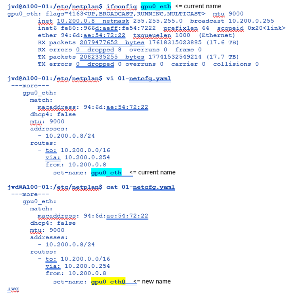
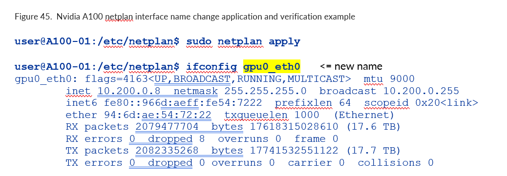
使用 netplan apply 命令应用更改
图 103.Nvidia A100 网络计划接口名称更改应用和验证示例
更改当前 IP 地址或将 IP 地址分配给 NIC
在配置文件中的相应接口下更改或添加地址,然后保存更改:
图 104.Nvidia A100 网络计划接口 IP 地址更改示例
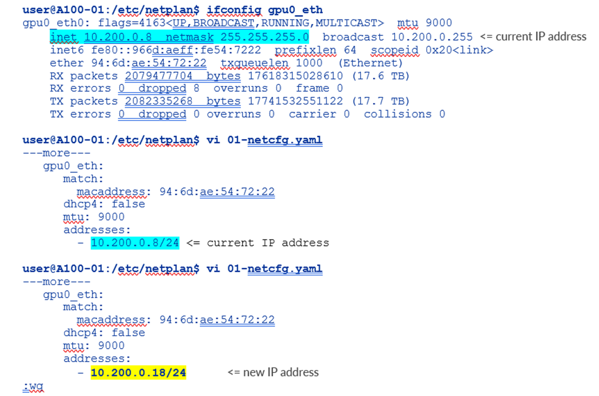
输入前面带连字符并缩进的 IP 地址;确保添加子网掩码。
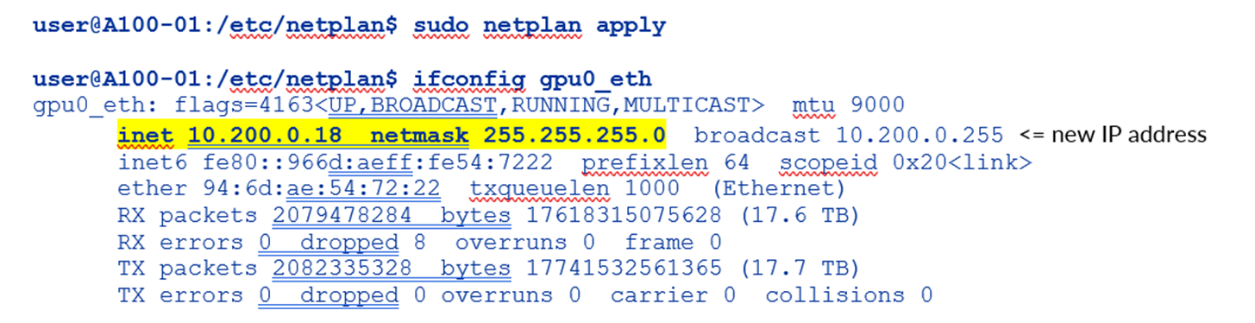
使用 netplan apply 命令应用更改
图 105.Nvidia A100 网络计划接口新 IP 地址应用和验证示例
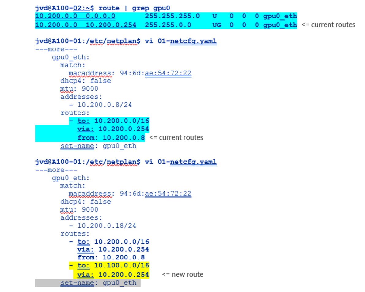
更改路由或添加到 NIC
在配置文件中的相应接口下更改或添加路由,然后保存更改。
图 106.Nvidia A100 netplan 附加路由示例
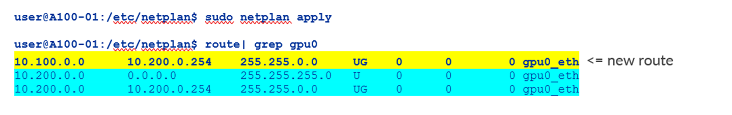
使用 netplan apply 命令应用更改
图 107.Nvidia A100 netplan 附加路由应用和验证示例:
配置 NVIDIA DCQCN – ECN
图 108:NVIDIA DCQCN – ECN
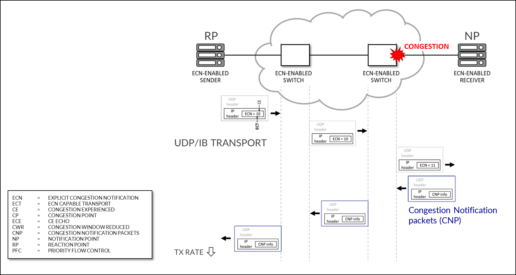
从 MLNX_OFED 4.1 开始,默认启用 ECN(在固件中)。
要确认已启用 ECN,请使用以下命令: mlxconfig -d <device> q | grep ROCE_CC
示例:
-
root@A100-01:/home/ylara# mlxconfig -d mlx5_0 q | grep ROCE_CC

         ROCE_CC_PRIO_MASK_P1        255

         ROCE_CC_PRIO_MASK_P2        255
掩码 255 表示已为 NIC 上配置的所有 TC(流量类)启用 DCQCN (ECN)。
要禁用 ECN,可以使用以下命令更改掩码: mlxconfig -d <device> s ROCE_CC_PRIO_MASK_P1=<mask>
示例:
-
root@A100-01:/home/ylara# sudo mlxconfig -d mlx5_0 s ROCE_CC_PRIO_MASK_P1=0

Device #1:

----------

Device type:    ConnectX7

Name:           MCX755106AS-HEA_Ax

Description:    NVIDIA ConnectX-7 HHHL Adapter Card; 200GbE (default mode) / NDR200 IB; Dual-port QSFP112; PCIe 5.0 x16 with x16 PCIe extension option; Crypto Disabled; Secure Boot Enabled

Device:         mlx5_0

Configurations:                                      Next Boot       New

         ROCE_CC_PRIO_MASK_P1                        0               0

 Apply new Configuration? (y/n) [n] :
如果要避免系统询问是否要应用新配置,请添加 -y 选项,如以下示例所示:
-
root@A100-01:/home/ylara# sudo mlxconfig -d mlx5_0 -y s ROCE_CC_PRIO_MASK_P1=0

Device #1:

----------

Device type:    ConnectX7

Name:           MCX755106AS-HEA_Ax

Description:    NVIDIA ConnectX-7 HHHL Adapter Card; 200GbE (default mode) / NDR200 IB; Dual-port QSFP112; PCIe 5.0 x16 with x16 PCIe extension option; Crypto Disabled; Secure Boot Enabled

Device:         mlx5_0

Configurations:                                      Next Boot       New

         ROCE_CC_PRIO_MASK_P1                        0               0

 Apply new Configuration? (y/n) [n] : y

Applying... Done!

-I- Please reboot machine to load new configurations.
输出指出需要重新启动服务器。或者,您可以使用以下命令重置接口: mlxfwreset -d <device> -l 3 -y r。
示例:
-
root@A100-01:/home/ylara# mlxfwreset -d mlx5_0 -l 3 -y r

Requested reset level for device, /dev/mst/mt4129_pciconf2:

3: Driver restart and PCI reset

Continue with reset?[y/N] y

-I- Sending Reset Command To Fw             -Done

-I- Stopping Driver                         -Done

-I- Resetting PCI                           -Done

-I- Starting Driver                         -Done

-I- Restarting MST                          -Done

-I- FW was loaded successfully.
ECN作参数位于以下路径上: /sys/class/net/<interface>/ecn
使用以下命令查找接口:
-
jvd@A100-01:~/$ ls /sys/class/net/

docker0   enp14s0f1np1 enp17s0f1np1 enp44s0f1np1  gpu0_eth  gpu3_eth  gpu6_eth mgmt_eth

enp139s0f1np1 enp169s0f0np0 enp200s0f1np1 enp81s0f1np1 gpu1_eth gpu4_eth gpu7_eth usb0

enp142s0f1np1 enp169s0f1np1 enp203s0f1np1 enp82s0f1np1 gpu2_eth gpu5_eth lo

jvd@A100-01:/sys/class/net/gpu0_eth/ecn$ ls

roce_np  roce_rp
通知点 (NP) 参数
启用 ECN 的接收方收到带有 ECN 标记的 RoCE 数据包时,会通过发送 CNP(拥塞通知数据包)进行响应。
以下命令描述通知参数:
-
jvd@A100-01:/sys/class/net/gpu0_eth/ecn$ ls /roce_np/

cnp_802p_prio  cnp_dscp  enable  min_time_between_cnps
示例:
-
jvd@A100-01:/sys/class/net/gpu0_eth/ecn$ cat roce_np/cnp_802p_prio

6
cnp_802p_prio = CNP 数据包的 PCP(优先级代码点)字段的值。
PCP 是使用 IEEE 802.1Q 定义的 VLAN 标记帧时,以太网帧头中的一个 3 位字段。
-
jvd@A100-01:/sys/class/net/gpu0_eth/ecn$ cat roce_np/cnp_dscp

48
cnp_dscp = CNP 数据包的 DSCP(差异化服务代码点)字段的值。
-
jvd@A100-01:/sys/class/net/gpu0_eth/ecn$ cat roce_np/min_time_between_cnps

4
min_time_between_cnps = 发送的两个连续 CNP 之间的最短时间。如果 ECN 标记的 RoCE 数据包到达的时间小于 min_time_between_cnps 自上次发送的 CNP 以来,则不会发送任何 CNP 作为响应。此值以微秒为单位。默认值 = 0
-
jvd@A100-01:/sys/class/net/gpu0_eth/ecn$ cat roce_np/enable/*

1

1

1

1

1

1

1

1
输出显示,roce_np已为所有优先级值启用。
要更改上述属性,请使用 mlxconfig 实用程序:
-
mlxconfig -d /dev/mst/<mst_module> -y s CNP_DSCP_P1=<value> CNP_802P_PRIO_P1=<value>
示例:
-
jvd@A100-01:/dev/mst$ sudo mst start

Starting MST (Mellanox Software Tools) driver set

Loading MST PCI module - Success

[warn] mst_pciconf is already loaded, skipping

Create devices

Unloading MST PCI module (unused) – Success

jvd@A100-01:~/scripts$ ./map_full_mellanox.sh

Mellanox Device to mlx and Network Interface Mapping:

/dev/mst/mt4123_pciconf0 => mlx5_14 => enp169s0f0np0 (0000:a9:00.0)

/dev/mst/mt4125_pciconf0 => mlx5_4 => mgmt_eth (0000:2c:00.0)

/dev/mst/
                mt4129_pciconf0
               => mlx5_6 => gpu0_eth (0000:0e:00.0)

/dev/mst/mt4129_pciconf1 => mlx5_8 => gpu1_eth (0000:11:00.0)

/dev/mst/mt4129_pciconf2 => mlx5_0 => gpu2_eth (0000:51:00.0)

/dev/mst/mt4129_pciconf3 => mlx5_2 => gpu3_eth (0000:52:00.0)

/dev/mst/mt4129_pciconf4 => mlx5_16 => gpu4_eth (0000:8b:00.0)

/dev/mst/mt4129_pciconf5 => mlx5_18 => gpu5_eth (0000:8e:00.0)

/dev/mst/mt4129_pciconf6 => mlx5_10 => gpu7_eth (0000:c8:00.0)

/dev/mst/mt4129_pciconf7 => mlx5_12 => gpu6_eth (0000:cb:00.0)

jvd@A100-01:/sys/class/net/gpu0_eth/ecn$ sudo mlxconfig -d /dev/mst/
                mt4129_pciconf0
               -y set CNP_DSCP_P1=40 CNP_802P_PRIO_P1=7

Device #1:

----------

Device type:        ConnectX7

Name:               MCX755106AS-HEA_Ax

Description:        NVIDIA ConnectX-7 HHHL Adapter Card; 200GbE (default mode) / NDR200 IB; Dual-port QSFP112; PCIe 5.0 x16 with x16 PCIe extension option; Crypto Disabled; Secure Boot Enabled

Device:             /dev/mst/mt4129_pciconf0

Configurations:                                          Next Boot       New

        CNP_DSCP_P1                                 48                   40

        CNP_802P_PRIO_P1                            6                    7

Apply new Configuration? (y/n) [n] : y

Applying... Done!

-I- Please reboot machine to load new configurations.
反应点 (RP) 参数
启用 ECN 的发送方收到 CNP 数据包时,会通过减慢指定流的传输速度(优先级)来做出响应。
以下参数定义 CNP 数据包到达后流量的速率限制方式:
-
jvd@A100-01:/sys/class/net$ ls gpu0_eth/ecn/roce_rp/

clamp_tgt_rate  enable  rpg_ai_rate     rpg_max_rate    rpg_time_reset

clamp_tgt_rate_after_time_inc   initial_alpha_value     rpg_byte_reset  rpg_min_dec_fac

dce_tcp_g               rate_reduce_monitor_period              rpg_gd

rpg_min_rate            dce_tcp_rtt     rate_to_set_on_first_cnp

rpg_hai_rate                    rpg_threshold
示例:
-
jvd@A100-01:/sys/class/net/gpu0_eth/ecn$ cat roce_rp/enable/*

1

1

1

1

1

1

1

1

jvd@A100-01:/sys/class/net/gpu0_eth/ecn$ cat roce_rp/rpg_max_rate

0
rpg_max_rate = 反应点节点可以传输的最大速率。达到此限制后,RP 不再受速率限制。
此值以 Mbits/sec 为单位配置。默认值 = 0(全速 - 无最大值)
输出显示,roce_rp已为所有优先级值启用。
要检查 ECN 统计信息,请使用: ethtool -S <interface> |GREP ECN
示例:
-
jvd@A100-01:~/scripts$ ethtool -S gpu0_eth | grep ecn

     rx_ecn_mark: 0

     rx_xsk_ecn_mark: 0

     rx0_ecn_mark: 0

     rx1_ecn_mark: 0

     rx2_ecn_mark: 0

     rx3_ecn_mark: 0

     rx4_ecn_mark: 0

     rx5_ecn_mark: 0

     rx6_ecn_mark: 0

     rx7_ecn_mark: 0

     rx8_ecn_mark: 0

 ---more---
NVIDIA DCQCN – PFC 配置
IEEE 802.1Qbb 将暂停功能应用于以太网链路上的特定流量类别。
图 109:NVIDIA DCQCN – PFC 配置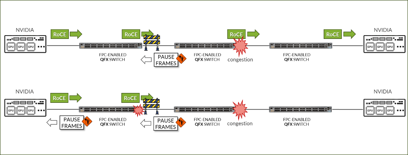
要检查接口上是否启用了 PFC,请使用: mlnx_qos -i <接口>
示例:
-
jvd@A100-01:/sys/class/net/gpu0_eth/ecn$ sudo mlnx_qos -i gpu0_eth

DCBX mode: OS controlled

Priority trust state: dscp

dscp2prio mapping:

        prio:0 dscp:07,06,05,04,03,02,01,00,

        prio:1 dscp:15,14,13,12,11,10,09,08,

        prio:2 dscp:23,22,21,20,19,18,17,16,

        prio:3 dscp:31,30,29,28,27,26,25,24,

        prio:4 dscp:39,38,37,36,35,34,33,32,

        prio:5 dscp:47,46,45,44,43,42,41,40,

        prio:6 dscp:55,54,53,52,51,50,49,48,

        prio:7 dscp:63,62,61,60,59,58,57,56,

default priority:

Receive buffer size (bytes): 19872,243072,0,0,0,0,0,0,max_buffer_size=2069280

Cable len: 7


                PFC configuration
              :

        priority    0   1   2
                3
                 4   5   6   7

        enabled     0   0   0
                1
                 0   0   0   0

        buffer      0   0   0
                1
                 0   0   0   0

tc: 0 ratelimit: unlimited, tsa: vendor

         priority:  1

tc: 1 ratelimit: unlimited, tsa: vendor

         priority:  0

tc: 2 ratelimit: unlimited, tsa: vendor

         priority:  2

tc: 3 ratelimit: unlimited, tsa: vendor

         priority:  3

tc: 4 ratelimit: unlimited, tsa: vendor

         priority:  4

tc: 5 ratelimit: unlimited, tsa: vendor

         priority:  5

tc: 6 ratelimit: unlimited, tsa: vendor

         priority:  6

tc: 7 ratelimit: unlimited, tsa: vendor

         priority:  7
要启用/禁用 PFC,请使用以下步骤: mlnx_qos -i <interface> --pfc <0/1>,<0/1>,<0/1>,<0/1>,<0/1>,<0/1>,<0/1>,<0/1>
示例:
- 检查当前配置:
-
jvd@A100-01:/sys/class/net/gpu0_eth/ecn$ sudo mlnx_qos -i gpu0_eth

DCBX mode: OS controlled

Priority trust state: dscp

dscp2prio mapping:

        prio:0 dscp:07,06,05,04,03,02,01,00,

        prio:1 dscp:15,14,13,12,11,10,09,08,

        prio:2 dscp:23,22,21,20,19,18,17,16,

        prio:3 dscp:31,30,29,28,27,26,25,24,

        prio:4 dscp:39,38,37,36,35,34,33,32,

        prio:5 dscp:47,46,45,44,43,42,41,40,

        prio:6 dscp:55,54,53,52,51,50,49,48,

        prio:7 dscp:63,62,61,60,59,58,57,56,

default priority:

Receive buffer size (bytes): 19872,243072,0,0,0,0,0,0,max_buffer_size=2069280

Cable len: 7


                PFC configuration
              :

        priority    0   1   2
                3
                 4   5   6   7

        enabled     0   0   0
                1
                 0   0   0   0

        buffer      0   0   0
                1
                 0   0   0   0

---more---
示例中的输出指示,已为优先级 3 启用 PFC。
- 为优先级 2 启用 PFC,为优先级 3 禁用 PFC:
-
jvd@A100-01:~/scripts$ sudo mlnx_qos -i gpu0_eth --pfc 0,0, 1 ,0,0,0,0,0 DCBX mode: OS controlled Priority trust state: dscp dscp2prio mapping: prio:0 dscp:07,06,05,04,03,02,01,00, prio:1 dscp:15,14,13,12,11,10,09,08, prio:2 dscp:23,22,21,20,19,18,17,16, prio:3 dscp:31,30,29,28,27,26,25,24, prio:4 dscp:39,38,37,36,35,34,33,32, prio:5 dscp:47,46,45,44,43,42,41,40, prio:6 dscp:55,54,53,52,51,50,49,48, prio:7 dscp:63,62,61,60,59,58,57,56, default priority: Receive buffer size (bytes): 19872,243072,0,0,0,0,0,0,max_buffer_size=2069280 Cable len: 7 PFC configuration: priority 0 1 2 3 4 5 6 7 enabled 0 0 1 0 0 0 0 0 buffer 0 0 1 0 0 0 0 0 ---more--- - 检查 PFC 统计信息:
jvd@A100-01:~/scripts$ ethtool -S gpu0_eth | grep pause

     rx_pause_ctrl_phy: 8143294

     tx_pause_ctrl_phy: 502


                rx_prio3
              _pause: 8143294


                rx_prio3
              _pause_duration: 10848932


                tx_prio3
              _pause: 502


                tx_prio3
              _pause_duration: 30445


                rx_prio3
              _pause_transition: 4071126

     tx_pause_storm_warning_events: 0

     tx_pause_storm_error_events: 0
用于 RDMA-CM QPS(RDMA 流量)的 NVIDIA TOS/DSCP 配置
图 110:NVIDIA TOS/DSCP
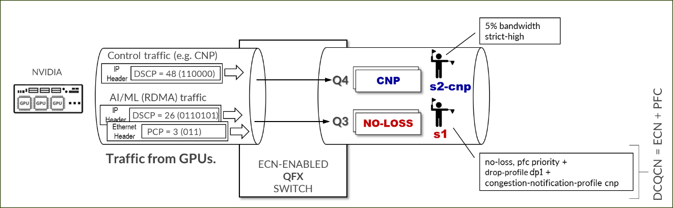
必须正确标记 RDMA 流量,以便交换机对其进行正确分类,并将其置于无损队列中以便进行正确处理。标记可以是 IP 报头中的 DSCP,也可以是以太网帧 vlan-tag 字段中的 PCP。是否使用 DSCP 或 PCP 取决于 GPU 服务器和交换机之间的接口是否正在执行 VLAN 标记 (802.1q)。
要检查当前配置并更改 RDMA 出站流量的 TOS 值,请使用 MLNX_OFED 4.0 中的 cma_roce_tos 脚本。
-
jvd@A100-01:/sys/class/net/gpu0_eth/ecn$ sudo cma_roce_tos -h

Set/Show RoCE default TOS of RDMA_CM applications

Usage:

        cma_roce_tos OPTIONS

Options:

        -h              show this help

        -d <dev>        use IB device <dev> (default mlx5_0)

        -p <port>       use port <port> of IB device (default 1)

        -t <TOS>        set TOS of RoCE RDMA_CM applications (0)
要检查 TOS 字段的当前值,请输入 sudo cma_roce_tos,不带任何选项。
示例:
-
jvd@A100-01:/sys/class/net/gpu0_eth/ecn$ sudo cma_roce_tos

106
在本例中,当前 TOS 值 = 106,这意味着 DSCP 值 = 48,ECN 位设置为 10。
要更改值,请使用: cma_roce_tos –d <ib_device> -t <TOS>
您需要在此命令中输入ib_device。以下脚本会自动执行物理接口与ib_device之间的映射。
-
map_full_mellanox.sh

#!/bin/bash

# Script to map Mellanox devices to mlx and network interfaces

# Get Mellanox device PCI addresses

mst_status=$(sudo mst status | awk '

//dev/mst/ {

    dev = $1

}

/domain:bus:dev.fn/ {

    pci = $1

    printf "%s: %s\n", dev, pci

}

')

# Get network interface PCI addresses

iface_status=$(for iface in $(ls /sys/class/net/); do

    pci_addr=$(ethtool -i $iface 2>/dev/null | grep bus-info | awk '{print $2}')

    if [ ! -z "$pci_addr" ]; then

        echo "$iface: $pci_addr"

    fi

done)

# Get network interface to mlx interface mapping

mlx_iface_status=$(for iface in $(ls /sys/class/net/); do

    if [ -d /sys/class/net/$iface/device/infiniband_verbs ]; then

        mlx_iface=$(cat /sys/class/net/$iface/device/infiniband_verbs/*/ibdev)

        echo "$iface: $mlx_iface"

    fi

done)

# Combine and print the mapping

echo "Mellanox Device to mlx and Network Interface Mapping:"

echo "$mst_status" | while read -r mst_line; do

    mst_dev=$(echo $mst_line | awk -F ': ' '{print $1}')

    mst_pci=$(echo $mst_line | awk -F '=| ' '{print $3}')

    iface=$(echo "$iface_status" | grep $mst_pci | awk -F ': ' '{print $1}')

    iface_pci=$(echo "$iface_status" | grep $mst_pci | awk -F ': ' '{print $2}')

    mlx_iface=$(echo "$mlx_iface_status" | grep $iface | awk -F ': ' '{print $2}')

    if [ ! -z "$iface" ] && [ ! -z "$mlx_iface" ]; then

        echo "$mst_dev => $mlx_iface => $iface ($iface_pci)"

    fi

done
示例:
图 111.脚本结果示例
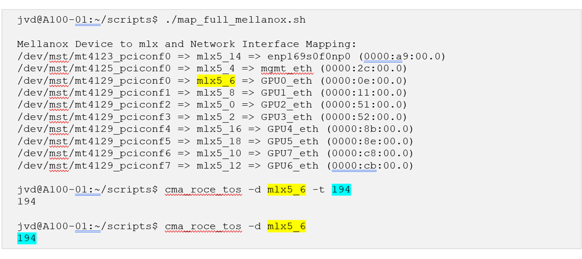
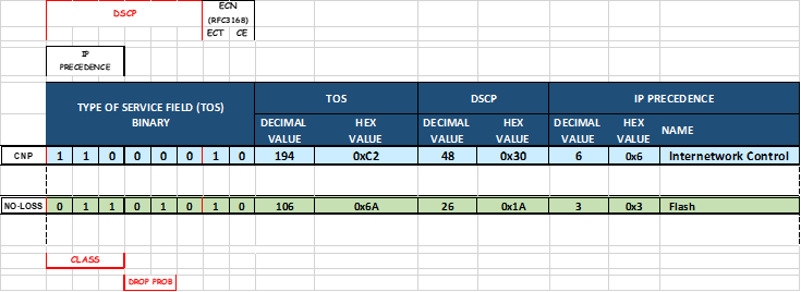
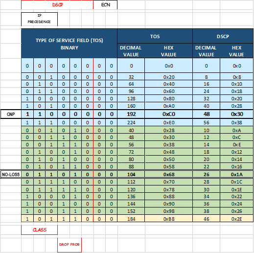
图 112.参考 TOS、DSCP 映射:
配置 NVIDIA 以使用 NCCL 控制流量的管理接口
NCCL 使用 TCP 会话将进程连接在一起,并交换 RoCE、GID(全局 ID)、本地和远程缓冲区地址、RDMA 密钥(用于内存访问权限的 RKEY)的 QP 信息
这些会话在作业启动时创建,默认情况下使用其中一个 GPU 接口(与用于 RoCEv2 流量的接口相同)。
示例:
-
ylara@A100-01:~$ netstat -atn | grep 10.200 | grep "ESTABLISHED"

tcp        0      0 10.200.4.8:47932        10.200.4.2:43131        ESTABLISHED

tcp        0      0 10.200.4.8:46699        10.200.4.2:37236        ESTABLISHED

tcp        0      0 10.200.2.8:60502        10.200.13.2:35547       ESTABLISHED

tcp        0      0 10.200.4.8:37330        10.200.4.2:55355        ESTABLISHED

tcp        0      0 10.200.4.8:56438        10.200.4.2:53947        ESTABLISHED

---more---
建议在启动作业时移至管理界面(连接到(前端交换矩阵),包括以下参数: export NCCL_SOCKET_IFNAME=“mgmt_eth”
示例:
-
ylara@A100-01:~$ netstat -atn | grep 10.10.1 | grep "ESTABLISHED"

tcp        0      0 10.10.1.0:44926         10.10.1.2:33149         ESTABLISHED

tcp        0      0 10.10.1.0:46705         10.10.1.0:40320         ESTABLISHED

tcp        0      0 10.10.1.0:54661         10.10.1.10:52452        ESTABLISHED

---more---