示例:配置基于 MPLS 的基本第 3 层 VPN
此示例说明如何在运行 Junos OS 的路由器或交换机上配置和验证基于 MPLS 的基本第 3 层 VPN。基于 IPv4 的示例使用 EBGP 作为提供商与客户边缘设备之间的路由协议。
我们的内容测试团队已经验证并更新了此示例。
您可以使用运行 Junos OS 的路由器和交换机部署基于 MPLS 的第 3 层虚拟专用网络 (VPN),通过第 3 层连接互连客户站点。虽然支持静态路由,但第 3 层 VPN 通常让客户设备与提供商网络交换路由信息,并且需要支持 IP 协议,即 IPv4 和/或 IPv6。
这与第 2 层 VPN 形成鲜明对比,在第 2 层 VPN 中,客户设备可能不基于 IP 协议,并且路由(如有)发生在客户边缘 (CE) 设备之间。与 CE 设备与提供商边缘设备交互(对等)的第 3 层 VPN 不同,在第 2 层 VPN 中,客户流量透明地通过提供商核心,任何路由协议都在 CE 设备之间运行端到端。
基于 MPLS 的 VPN 需要提供商网络中的基准 MPLS 功能。基本 MPLS 开始运行后,您就可以配置使用标签交换路径 (LSP) 通过提供商核心进行传输的 VPN。
添加 VPN 服务不会影响提供商网络中的基本 MPLS 交换作。事实上,提供商 (P) 设备不需要基准 MPLS 配置,因为它们无法感知 VPN。VPN 状态仅在提供商边缘 (PE) 设备上维护。这也是基于 MPLS 的 VPN 扩展性能如此之好的一个关键原因。
要求
此示例使用以下软件和硬件组件:
Junos OS 12.3 或更高版本(适用于路由和交换设备)
在 Junos OS 20.3R1 版上重新验证
两台提供商边缘 (PE) 设备
一个提供商 (P) 设备
两台客户边缘 (CE) 设备
该示例重点介绍如何将第 3 层 VPN 添加到预先存在的 MPLS 基准。如果您的网络尚未部署 MPLS,则会提供基本的 MPLS 配置。
要支持基于 MPLS 的 VPN,底层 MPLS 基准必须提供以下功能:
面向核心的环路接口,支持 MPLS 系列
OSPF 或 IS-IS 等内部网关协议,用于在提供商设备的环路地址(P 和 PE)之间提供可访问性
用于 LSP 信号的 MPLS 信令协议(如 LDP 或 RSVP)
在 PE 设备环路地址之间建立的 LSP
参与给定 VPN 的每对 PE 设备之间都需要 LSP。最好在所有 PE 设备之间构建 LSP,以适应未来的 VPN 增长。您可以在 [edit protocols mpls] 层级配置 LSP。与用于电路交叉连接 (CCC) 连接的 MPLS 配置不同,您无需手动将 LSP 与 PE 设备面向客户的(边缘)接口相关联。相反,第 3 层 VPN 使用 BGP 信令来通告站点可访问性。此 BGP 信令可自动将远程 VPN 站点映射到 LSP 转发下一跃点。这意味着,使用第 3 层 VPN,无需将 LSP 显式映射到 PE 设备的边缘接口。
概述和拓扑
通过第 3 层 VPN,客户可以利用服务提供商的技术专长来确保高效的站点到站点路由。客户边缘 (CE) 设备通常使用 BGP 或 OSPF 等路由协议与服务提供商边缘 (PE) 设备交换路由。第 3 层 VPN 支持静态路由,但通常首选动态路由协议。
VPN 的定义仅涉及对本地和远程 PE 设备的更改。提供商设备不需要其他配置(假设它们已具有有效的 MPLS 基准),因为这些设备仅提供基本的 MPLS 交换功能。CE 设备不使用 MPLS,只需要基本接口和路由协议配置,即可与 PE 设备交互。
在第 3 层 VPN 中,您可以将 CE 设备配置为与本地 PE 设备对等。这与第 2 层 VPN 形成鲜明对比,在 2 层 VPN 中,尽管 CE 设备通过基于 MPLS 的提供商核心进行连接,但它们彼此对等互连,就像它们在共享链路上一样。
建立 MPLS 基准后,您必须在 PE 设备上配置以下功能,以建立基于 MPLS 的第 3 层 VPN:
具有
family inet-vpn unicast支持的 BGP 组具有与附加的 CE 设备兼容的实例类型
vrf和路由协议定义的路由实例PE 设备上面向客户的接口配置了
family inetIPv4 地址,用于将接口与连接的 CE 设备位于同一子网中。如果需要,还可以配置 VLAN 封装和对应的 VLAN ID。
为了获得正确的端到端连接,需要为 CE 设备配置兼容的 IP 子网和路由协议参数,以支持与 PE 设备对等。
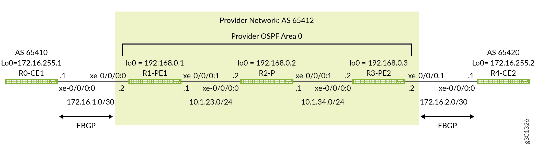
图 1 显示了此示例中使用的拓扑。该图详细说明了提供商和客户网络中使用的接口名称、IP 寻址和路由协议。它还突出显示了 CE 和 PE 设备之间的对等关系。在此示例中,您希望每个 CE 设备 与 本地 PE 设备形成 EBGP 对等会话。请注意,提供商网络和两个客户站点都分配了自治系统编号,以支持 BGP作。在此示例中,将路由策略应用于 CE 设备,以便它们为其面向提供商的环路接口通告直接路由。
快速配置
使用本部分中的配置可快速启动并运行基于 MPLS 的第 3 层 VPN。这些配置包括支持第 3 层 VPN 的功能性 MPLS 基准。此示例重点介绍配置的 VPN 方面。有关此示例中使用的基线 MPLS 功能的其他信息,请参阅以下链接:
CLI 快速配置
设备配置省略了管理界面、静态路由、系统日志记录、系统服务和用户登录信息。配置的这些部分因位置而异,与 MPLS 或 VPN 功能没有直接关系。
根据环境的具体情况编辑以下命令,并在层次结构的配置模式 [edit] 下,将其粘贴到本地 CE (CE1) 设备终端窗口中:
CE1 设备的完整配置。
set system host-name ce1
set interfaces xe-0/0/0:0 description "Link from CE1 to PE1 for L3vpn"
set interfaces xe-0/0/0:0 unit 0 family inet address 172.16.1.1/30
set interfaces lo0 unit 0 family inet address 172.16.255.1/32
set routing-options router-id 172.16.255.1
set routing-options autonomous-system 65410
set protocols bgp group PE1 type external
set protocols bgp group PE1 export adv_direct
set protocols bgp group PE1 peer-as 65412
set protocols bgp group PE1 neighbor 172.16.1.2
set policy-options policy-statement adv_direct term 1 from protocol direct
set policy-options policy-statement adv_direct term 1 from route-filter 172.16.0.0/16 orlonger
set policy-options policy-statement adv_direct term 1 then accept
PE1 设备的完整配置。
set system host-name pe1
set interfaces xe-0/0/0:0 description "Link from PE1 to CE1 for L3vpn"
set interfaces xe-0/0/0:0 unit 0 family inet address 172.16.1.2/30
set interfaces xe-0/0/0:1 description "Link from PE1 to p-router"
set interfaces xe-0/0/0:1 mtu 4000
set interfaces xe-0/0/0:1 unit 0 family inet address 10.1.23.1/24
set interfaces xe-0/0/0:1 unit 0 family mpls
set interfaces lo0 unit 0 family inet address 192.168.0.1/32
set routing-instances CE1_L3vpn protocols bgp group CE1 type external
set routing-instances CE1_L3vpn protocols bgp group CE1 peer-as 65410
set routing-instances CE1_L3vpn protocols bgp group CE1 neighbor 172.16.1.1
set routing-instances CE1_L3vpn instance-type vrf
set routing-instances CE1_L3vpn interface xe-0/0/0:0.0
set routing-instances CE1_L3vpn route-distinguisher 192.168.0.1:12
set routing-instances CE1_L3vpn vrf-target target:65412:12
set routing-options router-id 192.168.0.1
set routing-options autonomous-system 65412
set protocols bgp group ibgp type internal
set protocols bgp group ibgp local-address 192.168.0.1
set protocols bgp group ibgp family inet-vpn unicast
set protocols bgp group ibgp neighbor 192.168.0.3
set protocols mpls label-switched-path lsp_to_pe2 to 192.168.0.3
set protocols mpls interface xe-0/0/0:1.0
set protocols ospf traffic-engineering
set protocols ospf area 0.0.0.0 interface lo0.0 passive
set protocols ospf area 0.0.0.0 interface xe-0/0/0:1.0
set protocols rsvp interface lo0.0
set protocols rsvp interface xe-0/0/0:1.0
P 设备的完整配置。
set system host-name p
set interfaces xe-0/0/0:0 description "Link from p-router to PE1"
set interfaces xe-0/0/0:0 mtu 4000
set interfaces xe-0/0/0:0 unit 0 family inet address 10.1.23.2/24
set interfaces xe-0/0/0:0 unit 0 family mpls
set interfaces xe-0/0/0:1 description "Link from p-router to PE2"
set interfaces xe-0/0/0:1 mtu 4000
set interfaces xe-0/0/0:1 unit 0 family inet address 10.1.34.1/24
set interfaces xe-0/0/0:1 unit 0 family mpls
set interfaces lo0 unit 0 family inet address 192.168.0.2/32
set protocols mpls interface xe-0/0/0:0.0
set protocols mpls interface xe-0/0/0:1.0
set protocols ospf traffic-engineering
set protocols ospf area 0.0.0.0 interface lo0.0 passive
set protocols ospf area 0.0.0.0 interface xe-0/0/0:0.0
set protocols ospf area 0.0.0.0 interface xe-0/0/0:1.0
set protocols rsvp interface lo0.0
set protocols rsvp interface xe-0/0/0:0.0
set protocols rsvp interface xe-0/0/0:1.0
PE2 设备的完整配置。
set system host-name pe2
set interfaces xe-0/0/0:1 description "Link from PE2 to CE2 for L3vpn"
set interfaces xe-0/0/0:1 unit 0 family inet address 172.16.2.2/30
set interfaces xe-0/0/0:0 description "Link from PE2 to p-router"
set interfaces xe-0/0/0:0 mtu 4000
set interfaces xe-0/0/0:0 unit 0 family inet address 10.1.34.2/24
set interfaces xe-0/0/0:0 unit 0 family mpls
set interfaces lo0 unit 0 family inet address 192.168.0.3/32
set routing-instances CE2_L3vpn protocols bgp group CE2 type external
set routing-instances CE2_L3vpn protocols bgp group CE2 peer-as 65420
set routing-instances CE2_L3vpn protocols bgp group CE2 neighbor 172.16.2.1
set routing-instances CE2_L3vpn instance-type vrf
set routing-instances CE2_L3vpn interface xe-0/0/0:1.0
set routing-instances CE2_L3vpn route-distinguisher 192.168.0.3:12
set routing-instances CE2_L3vpn vrf-target target:65412:12
set routing-options router-id 192.168.0.3
set routing-options autonomous-system 65412
set protocols bgp group ibgp type internal
set protocols bgp group ibgp local-address 192.168.0.3
set protocols bgp group ibgp family inet-vpn unicast
set protocols bgp group ibgp neighbor 192.168.0.1
set protocols mpls label-switched-path lsp_to_pe1 to 192.168.0.1
set protocols mpls interface xe-0/0/0:0.0
set protocols ospf traffic-engineering
set protocols ospf area 0.0.0.0 interface lo0.0 passive
set protocols ospf area 0.0.0.0 interface xe-0/0/0:0.0
set protocols rsvp interface lo0.0
set protocols rsvp interface xe-0/0/0:0.0
CE2 设备的完整配置。
set system host-name ce2
set interfaces xe-0/0/0:0 description "Link from CE2 to PE2 for L3vpn"
set interfaces xe-0/0/0:0 unit 0 family inet address 172.16.2.1/30
set interfaces lo0 unit 0 family inet address 172.16.255.2/32
set routing-options router-id 172.16.255.2
set routing-options autonomous-system 65420
set protocols bgp group PE2 type external
set protocols bgp group PE2 export adv_direct
set protocols bgp group PE2 peer-as 65412
set protocols bgp group PE2 neighbor 172.16.2.2
set policy-options policy-statement adv_direct term 1 from protocol direct
set policy-options policy-statement adv_direct term 1 from route-filter 172.16.0.0/16 orlonger
set policy-options policy-statement adv_direct term 1 then accept
当您对工作感到满意时,请务必在所有设备上提交配置更改。恭喜您获得基于 MPLS 的全新第 3 层 VPN!请参阅 “验证 ”部分,了解确认您的第 3 层 VPN 是否按预期工作所需的步骤。
为基于 MPLS 的第 3 层 VPN 配置本地 PE (PE1) 设备
本节介绍在此示例中配置 PE1 设备所需的步骤。重点放在 PE 设备上,因为这是 VPN 配置所在的位置。请参阅 “快速配置 ”部分,了解此示例中使用的 CE 设备和 P 设备配置。
配置 MPLS 基准(如果需要)
配置第 3 层 VPN 之前,请确保 PE 设备具有有效的 MPLS 基准。如果已有 MPLS 基准,则可以跳到分步过程,将第 3 层 VPN 添加到 PE 设备。
配置主机名。
[edit]
user@pe1# set system host-name pe1
配置核心接口和环路接口:
[edit]
user@pe1# set interfaces xe-0/0/0:1 description "Link from PE1 to P-router"
[edit]
user@pe1# set interfaces xe-0/0/0:1 mtu 4000
[edit]
user@pe1# set interfaces xe-0/0/0:1 unit 0 family inet address 10.1.23.1/24
[edit]
user@pe1# set interfaces xe-0/0/0:1 unit 0 family mpls
[edit]
user@pe1# set interfaces lo0 unit 0 family inet address 192.168.0.1/32
最佳实践:虽然第 3 层 VPN 可以在入口 PE 上执行分段,但其最佳做法是设计网络,以便 CE 可以发送最大大小的帧而无需分段。为确保不会发生分段,提供商网络应支持 PE 设备添加 MPLS 和虚拟路由和转发 (VRF) 标签 后 CE 设备可以生成的最大帧。此示例将 CE 设备保留为默认的 1500 字节最大传输单元 (MTU),同时将提供商核心配置为支持 4000 字节 MTU。这可以确保 CE 设备不会超过提供商网络中的 MTU,即使有 MPLS 和 VRF 封装开销也是如此。
配置协议:
注意:RSVP 信号 LSP 支持流量工程,但基本 MPLS 交换或 VPN 部署不需要流量工程。提供的 MPLS 基准使用 RSVP 向 LSP 发出信号,并支持 OSPF 的流量工程。但是,未配置任何路径限制,因此您希望 LSP 通过内部网关协议的最短路径进行路由。
[edit]
user@pe1# set protocols ospf area 0.0.0.0 interface lo0.0 passive
[edit]
user@pe1# set protocols ospf area 0.0.0.0 interface xe-0/0/0:1.0
[edit]
user@pe1# set protocols ospf traffic-engineering
[edit]
user@pe1# set protocols mpls interface xe-0/0/0:1.0
[edit]
user@pe1# set protocols rsvp interface lo0.0
[edit]
user@pe1# set protocols rsvp interface xe-0/0/0:1.0
定义远程 PE 设备环路地址的 LSP:
[edit]
user@pe1#  set protocols mpls label-switched-path lsp_to_pe2 to 192.168.0.3
现在已在 PE1 设备上配置 MPLS 基准。继续配置第 3 层 VPN。
程序
分步过程
按照以下步骤为第 3 层 VPN 配置 PE1 设备。
配置面向客户的界面:
提示:您可以在同一 PE 设备上同时配置基于 MPLS 的第 2 层 VPN 和基于 MPLS 的第 3 层 VPN。但是,您不能将同一个面向客户边缘的接口配置为同时支持第 2 层 VPN 和第 3 层 VPN。
[edit interfaces]
user@pe1# set xe-0/0/0:0 description "Link from PE1 to CE1 for L3vpn"
[edit]
user@pe1# set xe-0/0/0:0 unit 0 family inet address 172.16.1.2/30
为本地和远程 PE 设备之间的对等互连配置 BGP 组。使用 PE 设备的环路地址作为本地地址,并启用
inet-vpn unicast地址族以支持第 3 层 VPN 路由交换。此示例中,PE 设备不需要 BGP 路由策略。默认情况下,PE 设备会向 IBGP 重新播发它们通过 EBGP 对等连接到 CE 设备而获知的路由。[edit protocols bgp] user@pe1# set group ibgp local-address 192.168.0.1 [edit protocols bgp] user@pe1# set group ibgp family inet-vpn unicast
提示:如果 PE 到 PE IBGP 会话需要支持非 VPN 路由交换,如分别使用
inet或inet6族的常规 IPv4 或 IPv6 路由,您可以指定其他地址族。将 BGP 组类型配置为内部。
[edit protocols bgp]
user@pe1# set group ibgp type internal
将远程 PE 设备的环路地址配置为 BGP 邻接方。
[edit protocols bgp]
user@pe1# set group ibgp neighbor 192.168.0.3
配置路由器 ID 以匹配其环路地址,并定义 BGP 对等互连所需的 BGP 自治系统编号。
[edit routing-options]
user@pe1# set router-id 192.168.0.1
[edit routing-options]
user@pe1# set autonomous-system 65412
配置路由实例。指定实例CE1_L3vpn名称 ,并配置
instance-type。vrf[edit routing-instances] user@pe1# set CE1_L3vpn instance-type vrf
将 PE 设备面向客户的接口配置为属于路由实例。
[edit routing-instances]
user@pe1# set CE1_L3vpn interface xe-0/0/0:0.0
配置路由实例的路由识别符。此设置用于区分从特定 PE 设备上的特定 VRF 发送的路由。对于每个 PE 设备上的每个路由实例,它应该是唯一的。
[edit routing-instances]
user@pe1# set CE1_L3vpn route-distinguisher 192.168.0.1:12
配置实例的虚拟路由和转发 (VRF) 表路由目标。该
vrf-target语句将指定的社区标记添加到所有播发的路由,同时自动匹配相同的路由导入值。为了实现正确的路由交换,需要在共享给定 VPN 的 PE 设备上配置匹配的路由目标。[edit routing-instances] user@pe1# set CE1_L3vpn vrf-target target:65142:12
注意:您可以通过使用导入和导出选项显式配置 VRF 导入和导出策略来创建更复杂的策略。有关详细信息,请参阅 vrf-import 和 vrf-export 。
配置路由实例以支持与 CE1 设备的 EBGP 对等互连。使用与 VRF 链路的 CE1 端的直接接口对等互连,并使用参数正确指定
peer-asCE1 的自治系统编号。[edit routing-instances] user@pe1# set CE1_L3vpn protocols bgp group CE1 type external [edit routing-instances] user@pe1# set CE1_L3vpn protocols bgp group CE1 peer-as 65410 [edit routing-instances] user@pe1# set CE1_L3vpn protocols bgp group CE1 neighbor 172.16.1.1
在 PE1 设备上提交更改,然后返回到 CLI作模式。
[edit]
user@pe1# commit and-quit
结果
显示 PE1 设备上的配置结果。输出仅反映此示例中添加的功能配置。
user@pe1> show configuration
interfaces {
    xe-0/0/0:0 {
        description "Link from PE1 to CE1 for L3vpn";
        unit 0 {
            family inet {
                address 172.16.1.2/30;
            }
        }
    }
    xe-0/0/0:1 {
        description "Link from PE1 to p-router";
        mtu 4000;
        unit 0 {
            family inet {
                address 10.1.23.1/24;
            }
            family mpls;
        }
    }
    lo0 {
        unit 0 {
            family inet {
                address 192.168.0.1/32;
            }
        }
    }
}

routing-instances {
    CE1_L3vpn {
        protocols {
            bgp {
                group CE1 {
                    type external;
                    peer-as 65410;
                    neighbor 172.16.1.1;
                }
            }
        }
        instance-type vrf;
        interface xe-0/0/0:0.0;
        route-distinguisher 192.168.0.1:12;
        vrf-target target:65412:12;
    }
}
routing-options {
    router-id 192.168.0.1;
    autonomous-system 65412;
}
protocols {
    bgp {
        group ibgp {
            type internal;
            local-address 192.168.0.1;
            family inet-vpn {
                unicast;
            }
            neighbor 192.168.0.3;
        }
    }
    mpls {
        label-switched-path lsp_to_pe2 {
            to 192.168.0.3;
        }
        interface xe-0/0/0:1.0;
    }
    ospf {
        traffic-engineering;
        area 0.0.0.0 {
            interface lo0.0 {
                passive;
            }
            interface xe-0/0/0:1.0;
        }
    }
    rsvp {
        interface lo0.0;
        interface xe-0/0/0:1.0;
    }
}
为基于 MPLS 的第 3 层 VPN 配置远程 PE (PE2) 设备
本节介绍在此示例中配置 PE1 设备所需的步骤。重点放在 PE 设备上,因为这是 VPN 配置所在的位置。请参阅 “快速配置 ”部分,了解此示例中使用的 CE 设备和 P 设备配置。
配置 MPLS 基准(如果需要)
配置第 3 层 VPN 之前,请确保 PE 设备具有有效的 MPLS 基准。如果已有 MPLS 基准,则可以跳到分步过程,将第 3 层 VPN 添加到 PE 设备。
配置主机名。
[edit]
user@pe2# set system host-name pe2
配置核心接口和环路接口:
[edit]
user@pe2# set interfaces xe-0/0/0:0 description "Link from PE2 to P-router"
[edit]
user@pe2# set interfaces xe-0/0/0:0 mtu 4000
[edit]
user@pe2# set interfaces xe-0/0/0:0 unit 0 family inet address 10.1.34.2/24
[edit]
user@pe2# set interfaces xe-0/0/0:0 unit 0 family mpls
[edit]
user@pe2# set interfaces lo0 unit 0 family inet address 192.168.0.3/32
最佳实践:虽然第 3 层 VPN 可以在入口 PE 上执行分段,但其最佳做法是设计网络,以便 CE 可以发送最大大小的帧而无需分段。为确保不会发生分段,提供商网络应支持 PE 设备添加 MPLS 和虚拟路由和转发 (VRF) 标签 后 CE 设备可以生成的最大帧。此示例将 CE 设备保留为默认的 1500 字节最大传输单元 (MTU),同时将提供商核心配置为支持 4000 字节 MTU。这可以确保 CE 设备不会超过提供商网络中的 MTU,即使有 MPLS 和 VRF 封装开销也是如此。
配置协议:
注意:RSVP 信号 LSP 支持流量工程,但基本 MPLS 交换或 VPN 部署不需要流量工程。提供的 MPLS 基准使用 RSVP 向 LSP 发出信号,并支持 OSPF 的流量工程。但是,未配置任何路径限制,因此您希望 LSP 通过内部网关协议的最短路径进行路由。
[edit]
user@pe2# set protocols ospf area 0.0.0.0 interface lo0.0 passive
[edit]
user@pe2# set protocols ospf area 0.0.0.0 interface xe-0/0/0:0.0
[edit]
user@pe2# set protocols ospf traffic-engineering
[edit]
user@pe2# set protocols mpls interface xe-0/0/0:0.0
[edit]
user@pe2# set protocols rsvp interface lo0.0
[edit]
user@pe2# set protocols rsvp interface xe-0/0/0:0.0
定义远程 PE 设备环路地址的 LSP:
[edit]
user@pe2# set protocols mpls label-switched-path lsp_to_pe1 to 192.168.0.1
现在已在 PE1 设备上配置 MPLS 基准。继续配置第 3 层 VPN。
程序
分步过程
请按照以下步骤为第 3 层 VPN 配置 PE2 设备。
配置面向客户的界面:
提示:您可以在同一 PE 设备上同时配置基于 MPLS 的第 2 层 VPN 和基于 MPLS 的第 3 层 VPN。但是,您不能将同一个面向客户边缘的接口配置为同时支持第 2 层 VPN 和第 3 层 VPN。
[edit interfaces]
user@pe2# set xe-0/0/0:1 description "Link from PE2 to CE2 for L3vpn"
[edit]
user@pe2# set xe-0/0/0:1 unit 0 family inet address 172.16.2.2/30
为本地和远程 PE 设备之间的对等互连配置 BGP 组。使用 PE 设备的环路地址作为本地地址,并启用
inet-vpn unicast地址族以支持第 3 层 VPN 路由交换。[edit protocols bgp] user@pe1# set group ibgp local-address 192.168.0.1 [edit protocols bgp] user@pe1# set group ibgp family inet-vpn unicast
提示:如果 PE 到 PE IBGP 会话需要支持非 VPN 路由交换,如分别使用
inet或inet6族的常规 IPv4 或 IPv6 路由,您可以指定其他地址族。将 BGP 组类型配置为内部。
[edit protocols bgp]
user@pe2# set group ibgp type internal
将 PE1 设备的环路地址配置为 BGP 邻接方。
[edit protocols bgp]
user@pe2# set group ibgp neighbor 192.168.0.1
配置路由器 ID 以匹配其环路地址,并定义 BGP 自治系统编号。
[edit routing-options]
user@pe2# set routing-options router-id 192.168.0.3
[edit routing-options]
user@pe2# set autonomous-system 65412
配置路由实例。指定实例名称 CE2_L3vpn,并用
instance-type。vrf[edit routing-instances] user@pe2# set CE2_L3vpn instance-type vrf
将 PE 设备面向客户的接口配置为属于路由实例。
[edit routing-instances]
user@pe2# set CE2_L3vpn interface xe-0/0/0:1.0
配置路由实例的路由识别符。此设置用于区分从特定 PE 设备上的特定 VRF 发送的路由。对于每个 PE 设备上的每个路由实例,它应该是唯一的。
[edit routing-instances]
user@pe2# set CE2_L3vpn route-distinguisher 192.168.0.3:12
配置实例的虚拟路由和转发 (VRF) 表路由目标。该
vrf-target语句将指定的社区标记添加到所有播发的路由,同时自动匹配相同的路由导入值。为了实现正确的路由交换,需要在共享给定 VPN 的 PE 设备上配置匹配的路由目标。[edit routing-instances] user@pe2# set CE2_L3vpn vrf-target target:65412:12
注意:您可以通过使用导入和导出选项显式配置 VRF 导入和导出策略来创建更复杂的策略。有关详细信息,请参阅 vrf-import 和 vrf-export 。
将路由实例配置为支持与 CE2 设备的 EBGP 对等互连。使用与 VRF 链路的 CE2 端的直接接口对等互连,并使用参数正确指定
peer-asCE2 的自治系统编号。[edit routing-instances] user@pe2# set CE2_L3vpn protocols bgp group CE2 type external [edit routing-instances] user@pe2# set CE2_L3vpn protocols bgp group CE2 peer-as 65420 [edit routing-instances] user@pe2# set CE2_L3vpn protocols bgp group CE2 neighbor 172.16.2.1
在 PE2 设备上提交更改,然后返回到 CLI作模式。
[edit]
user@pe2# commit and-quit
结果
显示 PE2 设备上的配置结果。输出仅反映此示例中添加的功能配置。
user@pe2> show configuration
interfaces {
    xe-0/0/0:0 {
        description "Link from PE2 to p-router";
        mtu 4000;
        unit 0 {
            family inet {
                address 10.1.34.2/24;
            }
            family mpls;
        }
    }
    xe-0/0/0:1 {
        description "Link from PE2 to CE2 for L3vpn";
        unit 0 {
            family inet {
                address 172.16.2.2/30;
            }
        }
    }
    lo0 {
        unit 0 {
            family inet {
                address 192.168.0.3/32;
            }
        }
    }
}
routing-instances {
    CE2_L3vpn {
        protocols {
            bgp {
                group CE2 {
                    type external;
                    peer-as 65420;
                    neighbor 172.16.2.1;
                }
            }
        }
        instance-type vrf;
        interface xe-0/0/0:1.0;
        route-distinguisher 192.168.0.3:12;
        vrf-target target:65412:12;
    }
}
routing-options {
    router-id 192.168.0.3;
    autonomous-system 65412;
}
protocols {
    bgp {
        group ibgp {
            type internal;
            local-address 192.168.0.3;
            family inet-vpn {
                unicast;
            }
            neighbor 192.168.0.1;
        }
    }
    mpls {
        label-switched-path lsp_to_pe1 {
            to 192.168.0.1;
        }
        interface xe-0/0/0:0.0;
    }
    ospf {
        traffic-engineering;
        area 0.0.0.0 {
            interface lo0.0 {
                passive;
            }
            interface xe-0/0/0:0.0;
        }
    }
    rsvp {
        interface lo0.0;
        interface xe-0/0/0:0.0;
    }
}
验证
执行以下任务以验证基于 MPLS 的第 3 层 VPN 是否工作正常:
- 验证提供商 OSPF 邻接和路由交换
- 验证 MPLS 和 RSVP 接口设置
- 验证 RSVP 信号 LSP
- 验证 BGP 会话状态
- 验证路由表中的第 3 层 VPN 路由
- 使用第 3 层 VPN 连接对远程 PE 设备执行 Ping 命令
- 验证 CE 设备通过第 3 层 VPN 的端到端作
- 特定于平台的 MPLS 第 3 层 VPN 行为
验证提供商 OSPF 邻接和路由交换
目的
通过验证邻接状态和 OSPF 学习的路由到远程提供商设备的环路地址,确认 OSPF 协议在提供商网络中工作正常。正确的 IGP作对于成功建立 MPLS LSP 至关重要。
行动
user@pe1> show ospf neighbor

Address          Interface              State           ID               Pri  Dead
10.1.23.2        xe-0/0/0:1.0           Full            192.168.0.2      128    37
user@pe1> show route protocol ospf | match 192.168

192.168.0.2/32     *[OSPF/10] 1w1d 23:59:43, metric 1
192.168.0.3/32     *[OSPF/10] 1w1d 23:59:38, metric 2
意义
输出显示 PE1 设备已与 P 设备 (192.168.0.2) 建立 OSPF 邻接关系。它还显示,通过本地 PE 设备的 OSPF 可以正确学习 P 和远程 PE 设备环路地址 (192.168.0.2) 和 (192.168.0.3)。
验证 MPLS 和 RSVP 接口设置
目的
验证 RSVP 和 MPLS 协议是否配置为在 PE 设备面向核心的接口上运行。此步骤还会验证 family mpls 是否在 PE 设备面向核心的接口的单元级别正确配置。
行动
user@pe1> show mpls interface

Interface        State       Administrative groups (x: extended)
xe-0/0/0:1.0     Up         <none>
user@pe1> show rsvp interface

RSVP interface: 2 active
                          Active  Subscr- Static      Available   Reserved    Highwater
Interface          State  resv    iption  BW          BW          BW          mark
lo0.0                  Up       0   100%  0bps        0bps        0bps        0bps
xe-0/0/0:1.0           Up       1   100%  10Gbps      10Gbps      0bps        0bps
意义
输出显示,本地 PE 设备的核心和环路接口上已正确配置 MPLS 和 RSVP。
验证 RSVP 信号 LSP
目的
验证 RSVP 信号入口和出口 LSP 是否已在 PE 设备的环路地址之间正确建立。
行动
user@pe1> show rsvp session

Ingress RSVP: 1 sessions
To              From            State   Rt Style Labelin Labelout LSPname
192.168.0.3     192.168.0.1     Up       0  1 FF       -       17 lsp_to_pe2
Total 1 displayed, Up 1, Down 0

Egress RSVP: 1 sessions
To              From            State   Rt Style Labelin Labelout LSPname
192.168.0.1     192.168.0.3     Up       0  1 FF       3        - lsp_to_pe1
Total 1 displayed, Up 1, Down 0

Transit RSVP: 0 sessions
Total 0 displayed, Up 0, Down 0
意义
输出显示已在 PE 设备之间正确建立入口和出口 RSVP 会话。成功建立 LSP 表明 MPLS 基准已正常运行。
验证 BGP 会话状态
目的
验证 PE 设备之间的 IBGP 会话是否已正确建立,并支持第 3 层 VPN 网络层可达性信息 (NLRI)。在此步骤中,您还将确认本地 PE 到 CE EBGP 会话已建立并正确配置为交换 IPv4 路由。
行动
user@pe1> show bgp summary

Groups: 2 Peers: 2 Down peers: 0
Table          Tot Paths  Act Paths Suppressed    History Damp State    Pending
inet.0
                       0          0          0          0          0          0
bgp.l3vpn.0
                       2          2          0          0          0          0
Peer                     AS      InPkt     OutPkt    OutQ   Flaps Last Up/Dwn State|#Active/Received/Accepted/Damped...
172.16.1.1            65410      26038      25938       0       0 1w1d 3:12:32 Establ
  CE1_L3vpn.inet.0: 1/2/2/0
192.168.0.3           65412         19         17       0       0        6:18 Establ
  CE1_L3vpn.inet.0: 2/2/2/0
  bgp.l3vpn.0: 2/2/2/0
意义
输出显示到远程 PE 设备 (192.168.0.3) 的 IBGP 会话已正确建立 (Establ),并通过 Up/Dwn 字段显示会话处于当前状态 ()6:18 的时间。字段 flaps 确认未发生状态转换 (0),表示会话稳定。另请注意,已从远程 PE 中学习了第 3 层 VPN 路由 (NLRI),如表的存在 bgp.l3vpn.0 所示。
显示屏还会确认与本地 CE1 设备 (172.16.1.1) 的 EBGP 会话已建立,并且已从 CE1 设备接收 IPv4 路由并安装在 CE1 设备路由实例 (CE1_L3vpn.inet.0) 中
此输出确认 PE 设备之间以及与 CE 设备之间的 BGP 对等互连是否工作正常,以支持您的第 3 层 VPN。
验证路由表中的第 3 层 VPN 路由
目的
确认 PE1 设备上的路由表中填充了由远程 PE 播发的第 3 层 VPN 路由。这些路由用于将流量转发至远程 CE 设备。
行动
user@pe1> show route table bgp.l3vpn.0

bgp.l3vpn.0: 2 destinations, 2 routes (2 active, 0 holddown, 0 hidden)
+ = Active Route, - = Last Active, * = Both

192.168.0.3:12:172.16.2.0/30
                   *[BGP/170] 00:22:45, localpref 100, from 192.168.0.3
                      AS path: I, validation-state: unverified
                    >  to 10.1.23.2 via xe-0/0/0:1.0, label-switched-path lsp_to_pe2
192.168.0.3:12:172.16.255.2/32
                   *[BGP/170] 00:22:43, localpref 100, from 192.168.0.3
                      AS path: 65420 I, validation-state: unverified
                    >  to 10.1.23.2 via xe-0/0/0:1.0, label-switched-path lsp_to_pe2
user@pe1> show route table CE1_L3vpn.inet.0

CE1_L3vpn.inet.0: 5 destinations, 6 routes (5 active, 0 holddown, 0 hidden)
+ = Active Route, - = Last Active, * = Both

172.16.1.0/30      *[Direct/0] 1w1d 03:29:44
                    >  via xe-0/0/0:0.0
                    [BGP/170] 1w1d 03:29:41, localpref 100
                      AS path: 65410 I, validation-state: unverified
                    >  to 172.16.1.1 via xe-0/0/0:0.0
172.16.1.2/32      *[Local/0] 1w1d 03:29:44
                       Local via xe-0/0/0:0.0
172.16.2.0/30      *[BGP/170] 00:23:28, localpref 100, from 192.168.0.3
                      AS path: I, validation-state: unverified
                    >  to 10.1.23.2 via xe-0/0/0:1.0, label-switched-path lsp_to_pe2
172.16.255.1/32    *[BGP/170] 1w1d 03:29:41, localpref 100
                      AS path: 65410 I, validation-state: unverified
                    >  to 172.16.1.1 via xe-0/0/0:0.0
172.16.255.2/32    *[BGP/170] 00:23:26, localpref 100, from 192.168.0.3
                      AS path: 65420 I, validation-state: unverified
                    >  to 10.1.23.2 via xe-0/0/0:1.0, label-switched-path lsp_to_pe2
意义
命令 show route table bgp.l3vpn.0 将显示已从远程 PE 设备接收的第 3 层 VPN 路由。命令 show route table CE1_L3vpn.inet.0 将列出已导入路由实例的所有 CE1_L3vpn 路由。这些条目表示从 CE1 设备的本地 EBGP 对等互连中获知的路由,以及从具有匹配路由目标的远程 PE2 设备接收的路由。
两个表均显示,远程第 3 层 VPN 路由已作为转发下一跃点与 lsp_to_pe2 LSP 正确关联。输出确认本地 PE 设备已从 PE2 设备获知与远程 CE2 位置关联的路由。它还显示,本地 PE 会通过提供商网络使用 MPLS 传输将第 3 层 VPN 流量转发到远程 PE2 设备。
使用第 3 层 VPN 连接对远程 PE 设备执行 Ping 命令
目的
使用 ping 验证本地和远程 PE 设备之间的第 3 层 VPN 连接。此命令验证 PE 设备之间的第 3 层 VPN 路由和 MPLS 转发作。
行动
user@pe1> ping routing-instance CE1_L3vpn 172.16.2.2 source 172.16.1.2 count 2

PING 172.16.2.2 (172.16.2.2): 56 data bytes
64 bytes from 172.16.2.2: icmp_seq=0 ttl=61 time=128.235 ms
64 bytes from 172.16.2.2: icmp_seq=1 ttl=61 time=87.597 ms

--- 172.16.2.2 ping statistics ---
2 packets transmitted, 2 packets received, 0% packet loss
round-trip min/avg/max/stddev = 87.597/107.916/128.235/20.319 m
意义
输出确认第 3 层 VPN 控制和转发平面在 PE 设备之间正常运行。
验证 CE 设备通过第 3 层 VPN 的端到端作
目的
验证 CE 设备之间的第 3 层 VPN 连接。此步骤将确认 CE 设备是否具有作接口,并且已针对基于 EBGP 的第 3 层连接进行了正确配置。为此,我们需要验证本地 CE1 设备是否已学习远程 CE 设备的路由,并确认 CE 设备能够在其环路地址之间进行端到端传输流量。
行动
user@ce1> show route protocol bgp

inet.0: 12 destinations, 12 routes (12 active, 0 holddown, 0 hidden)
+ = Active Route, - = Last Active, * = Both

172.16.2.0/30      *[BGP/170] 00:40:50, localpref 100
                      AS path: 65412 I, validation-state: unverified
                    >  to 172.16.1.2 via xe-0/0/0:0.0
172.16.255.2/32    *[BGP/170] 00:40:49, localpref 100
                      AS path: 65412 65420 I, validation-state: unverified
                    >  to 172.16.1.2 via xe-0/0/0:0.0

inet6.0: 1 destinations, 1 routes (1 active, 0 holddown, 0 hidden)
user@ce1> ping 172.16.255.2 source 172.16.255.1 size 1472 do-not-fragment count 2

PING 172.16.255.2 (172.16.255.2): 1472 data bytes
1480 bytes from 172.16.255.2: icmp_seq=0 ttl=61 time=79.245 ms
1480 bytes from 172.16.255.2: icmp_seq=1 ttl=61 time=89.125 ms

--- 172.16.255.2 ping statistics ---
2 packets transmitted, 2 packets received, 0% packet loss
round-trip min/avg/max/stddev = 79.245/84.185/89.125/4.940 ms
意义
输出显示,基于第 3 层 VPN 的连接在 CE 设备之间工作正常。本地 CE 设备已通过 BGP 学习远程 CE 设备的 VRF 接口和环路。ping 将生成到远程 CE 设备的环路地址,并使用参数 source 172.16.255.1 从本地 CE 设备的环路地址获取。添加 do-not-fragment 和 size 1472 交换机可确认 CE 设备能够传递 1500 字节 IP 数据包,而不会在本地 PE 设备中引起分段。
size 1472添加到命令中的ping参数将生成 1472 字节的回显数据。另外增加了 8 个字节的互联网控制消息协议 (ICMP) 和 20 个字节的 IP 报头,使总有效负载大小达到 1500 字节。添加do-not-fragment交换机可确保本地 CE 和 PE 设备无法执行分段。此 ping 方法确认在 CE 设备之间交换标准 1500 字节最大长度以太网帧时不需要分段。
这些结果证实基于 MPLS 的第 3 层 VPN 工作正常。
特定于平台 的 MPLS 第 3 层 VPN 行为
使用 功能浏览器 确认平台和版本对特定功能的支持。
使用下表查看您的平台特定于平台的行为。
| 平台 |
差异 |
|---|---|
| ACX 7000 系列路由器 |
|