示例:配置第 2 层电路保护接口
此示例说明了您可以如何配置带有保护接口的第 2 层电路。保护接口可充当相关接口的备份。主接口具有保护接口的优先级,只要它起作用,就传输网络流量。如果主接口发生故障,将激活保护接口。这些接口还可以共享相同的虚拟路径标识符 (VPI) 或虚拟电路标识符 (VCI)。
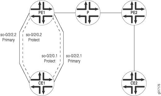
图 1 显示了此示例中使用的网络拓扑。
 的第 2 层电路
以下部分介绍如何将第 2 层电路配置为使用保护接口:
配置路由器 PE1
在层级配置从路由器 PE1 到路由器 CE1 的 [edit interfaces] 流量接口:
[edit interfaces]
so-0/2/2 {
    description "Router CE1 so-0/2/2";
    no-keepalives;
    encapsulation frame-relay-ccc;
    unit 1 {
        encapsulation frame-relay-ccc;
        point-to-point;
        dlci 600;
    }
    unit 2 {
        encapsulation frame-relay-ccc;
        point-to-point;
        dlci 602;
    }
}
配置一个接口,用于从路由器 PE1 到路由器 CE1 的 [edit interfaces] 流量。逻辑接口 so-0/2/0.2 充当保护接口 so-0/2/2.2,逻辑接口 so-0/2/0.1 用作以下项 so-0/2/2.1的保护接口:
[edit interfaces]
so-0/2/0 {
    description "to Router CE1 so-0/3/0";
    no-keepalives;
    encapsulation frame-relay-ccc;
    unit 1 {
        encapsulation frame-relay-ccc;
        dlci 600;
    }
    unit 2 {
        encapsulation frame-relay-ccc;
        dlci 602;
    }
}
在层级配置从路由器 PE1 到路由器 PE2 的 [edit interfaces] 流量接口:
[edit interfaces]
so-0/2/1 {
    description "to Router PE2 so-1/0/1";
    unit 0 {
        family inet {
            address 192.0.2.0/24 {
                destination 192.0.2.4;
            }
        }
        family iso;
        family mpls;
    }
}
在层级配置从路由器 PE1 到路由器 PE2 的 [edit interfaces] 流量接口:
[edit interfaces]
so-0/2/3 {
    description "Router PE2 so-1/0/3";
    unit 0 {
        family inet;
        family iso;
        family mpls;
    }
    lo0 {
        unit 0 {
            family inet {
                address 198.51.100.0/24;
                address 10.100.40.200/32;
            }
            family iso {
                address 47.0005.80ff.f800.0000.0108.0001.1921.6800.4213.00;
            }
        }
    }
}
通过在层次结构级别包含语句[edit protocols]来l2circuit配置第 2 层电路。此处包含第 2 层电路的逻辑接口及其相应的保护接口:
[edit protocols]
l2circuit {
    neighbor 10.100.40.210 {
        interface so-0/2/2.2 {
            protect-interface so-0/2/0.2;
            virtual-circuit-id 2;
            no-control-word;
        }
        interface so-0/2/2.1 {
            protect-interface so-0/2/0.1;
            virtual-circuit-id 1;
            no-control-word;
        }
    }
}
配置路由器 PE2
配置从路由器 PE2 到路由器 CE2 的流量接口:
[edit interfaces]
so-1/0/0 {
    description "to Router CE2 so-0/2/0";
    no-keepalives;
    encapsulation frame-relay-ccc;
    unit 1 {
        encapsulation frame-relay-ccc;
        point-to-point;
        dlci 700;
    }
    unit 2 {
        encapsulation frame-relay-ccc;
        point-to-point;
        dlci 702;
    }
}
配置从路由器 PE2 到路由器 PE1 的流量接口:
[edit interfaces]
so-1/0/1 {
    description "to Router PE1 so-0/2/1";
    unit 0 {
        family inet {
            address 192.0.2.4/32 {
                destination 192.0.2.22;
            }
        }
        family iso;
        family mpls;
    }
}
配置从路由器 PE2 到路由器 PE1 的流量接口:
[edit interfaces]
so-1/0/3 {
    description "to Router PE1 so-0/2/3";
    unit 0 {
        family inet;
        family iso;
        family mpls;
    }
}
lo0 {
    unit 0 {
        family inet {
            address 198.51.100.0/24;
            address 10.100.40.210/32;
        }
        family iso {
            address 47.0005.80ff.f800.0000.0108.0001.1921.6800.4216.00;
        }
    }
}
在层次结构级别配置第 2 层电路 [edit protocols] :
[edit protocols]
l2circuit {
    neighbor 10.100.40.200 {
        interface so-1/0/0.1 {
            virtual-circuit-id 1;
            no-control-word;
        }
        interface so-1/0/0.2 {
            virtual-circuit-id 2;
            no-control-word;
        }
    }
}
配置路由器 CE1
配置从路由器 CE1 到路由器 PE1 的流量接口:
[edit interfaces]
so-0/3/0 {
    description "to Router PE1 so-0/2/0";
    no-keepalives;
    encapsulation frame-relay;
    unit 1 {
        dlci 601;
        family inet {
            address 203.0.113.1;
        }
    }
}
配置从路由器 CE1 到路由器 PE1 的流量接口:
[edit interfaces]
so-0/3/1 {
    description "Router PE1 so-0/2/2";
    no-keepalives;
    encapsulation frame-relay;
    unit 0 {
        dlci 600;
        family inet {
            address 10.10.10.1/24;
            address 203.0.113.2/24;
        }
        family iso;
        family mpls;
    }
    unit 2 {
        dlci 602;
        family inet {
            address 203.0.113.3/24;
        }
    }
}
配置路由器 CE2
配置从路由器 CE2 到路由器 PE2 的流量接口:
[edit interfaces]
so-0/2/0 {
    description "to Router PE2 so-1/0/0";
    no-keepalives;
    encapsulation frame-relay;
    unit 1 {
        dlci 700;
        family inet {
            address 10.10.10.2/24;
            address 203.0.113.5/24;
            address 203.0.113.6/24;
        }
    }
    unit 2 {
        dlci 702;
        family inet {
            address 203.0.113.7/24;
        }
    }
}
