示例:配置基于 MPLS 的第 2 层 VPN
此示例说明如何在运行 Junos OS 的路由器或交换机上配置和验证基于 MPLS 的第 2 层 VPN。
我们的内容测试团队已经验证并更新了此示例。
您可以使用运行 Junos OS 的路由器和交换机部署基于 MPLS 的第 2 层虚拟专用网络,以便通过第 2 层连接将客户站点互连。第 2 层 VPN 让客户可以完全控制其传输和路由协议。
基于 MPLS 的 VPN 需要在提供商网络中提供基准 MPLS 功能。在基本 MPLS 正常运行后,您就可以配置使用标签交换路径 (LSP) 通过提供商核心进行传输的 VPN。
添加 VPN 服务不会影响提供商网络中的基本 MPLS 交换操作。事实上,提供商 (P) 设备只需基准 MPLS 配置,因为它们无法感知 VPN。仅在 PE 设备上维护 VPN 状态。这是基于 MPLS 的 VPN 如此可扩展的关键原因。
要求
此示例使用以下硬件和软件组件:
Junos OS 15.1 或更高版本
在 Junos OS 20.1R1 版上重新验证
两个提供商边缘 (PE) 设备
一个提供商 (P) 设备
两个客户边缘 (CE) 设备
示例重点介绍如何将第 2 层 VPN 添加到预先存在的 MPLS 基准中。如果您的网络尚未部署 MPLS,则提供基本 MPLS 配置。
要支持基于 MPLS 的 VPN,底层 MPLS 基准必须提供以下功能:
采用 MPLS 系列支持的面向核心的环路接口
一种内部网关协议,如 OSPF 或 IS-IS,在提供商(P 和 PE)设备的环路地址之间提供可访问性
用于发送 LSP 信号的 MPLS 信令协议,如 LDP 或 RSVP
在 PE 设备环路地址之间建立的 LSP
参与给定 VPN 的每对 PE 设备之间需要 LSP。最好在所有 PE 设备之间构建 LSP,以适应未来的 VPN 增长。您可以在层次结构级别配置 LSP [edit protocols mpls] 。与用于电路交叉连接 (CCC) 的 MPLS 配置不同,您不需要手动将 LSP 与 PE 设备的面向客户的(边缘)接口相关联。相反,第 2 层 VPN 使用 BGP 信令传达第 2 层站点可访问性。此 BGP 信令可自动将远程第 2 层 VPN 站点映射到 LSP 转发下一跃点。这意味着,使用第 2 层 VPN 时,LSP 无需将 LSP 显式映射到 PE 设备的面向边缘的接口。
有关 CCC 的详细信息,请参阅 使用第 2 层电路配置基于 MPLS 的 VLAN CCC。
概述和拓扑
第 2 层 VPN 在提供商网络和客户网络之间提供完全分离。第 2 层 VPN 的优势包括支持非标准传输协议,以及隔离客户和提供商网络之间的链路寻址和路由协议操作。
VPN 的定义仅涉及对本地和远程 PE 设备的更改。提供商设备上不需要其他配置(基准 MPLS 支持例外),因为这些设备仅提供基本的 MPLS 交换功能。CE 设备不使用 MPLS。它们只需一个基本接口(如果需要的话)即可在第 2 层 VPN 上运行协议配置。对于第 2 层 VPN,您可以将 CE 设备配置为已连接到共享链路。
确定 MPLS 基准后,您必须在 PE 设备上配置以下功能,以建立基于 MPLS 的第 2 层 VPN:
包含
family l2vpn signaling具有实例类型的路由实例
l2vpnPE 设备上面向客户的接口必须按如下配置:
根据是否正在使用 VLAN 标记指定
ethernet-ccc或vlan-ccc物理层封装。在路由实例配置中配置匹配的封装类型。
配置用于第 2 层 VPN 的
family ccc逻辑接口(单元)。
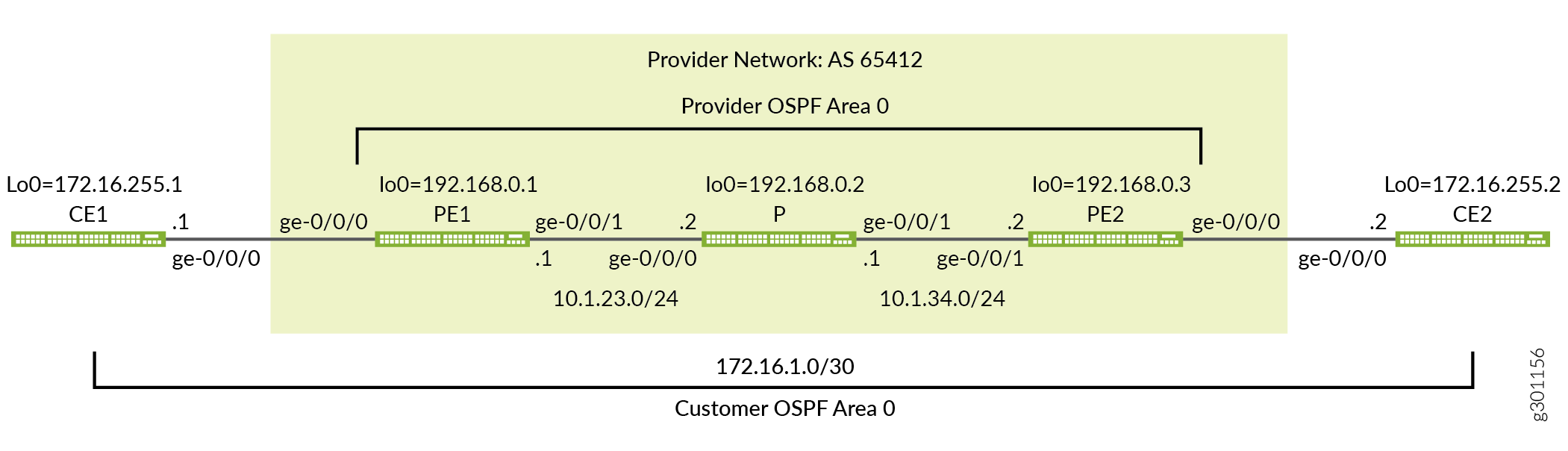
图 1 提供了这个基于 MPLS 的第 2 层 VPN 示例的拓扑结构。该图详细介绍了提供商网络中使用的接口名称、IP 寻址和协议。它还强调了 CE 设备寻址和协议堆栈操作的端到端特性。与第 3 层 VPN 不同,CE 设备操作对第 2 层 VPN 中的提供商网络不透明。CE 设备和提供商网络之间没有对等关系。因此,您期望 CE 设备在提供商网络上形成一个 OSPF 邻接, 而不是与提供商网络。
快速配置
使用本节中的配置快速启动和运行基于 MPLS 的第 2 层 VPN。这些配置包括一个实用的 MPLS 基准,可支持第 2 层 VPN。此示例重点介绍了配置的 VPN 方面。有关此示例中使用的基准 MPLS 功能的更多信息,请参阅以下链接:
CLI 快速配置
设备配置省略了管理接口、静态路由、系统日志记录、系统服务和用户登录信息。这些配置部分因位置而异,并且与 MPLS 或 VPN 功能不直接相关。
根据需要编辑以下命令,了解环境的具体信息,并将其粘贴到本地 CE (CE1) 设备终端窗口中:
CE1 设备的完整配置。
set system host-name ce1
set interfaces ge-0/0/0 description "Link from CE1 to PE1"
set interfaces ge-0/0/0 unit 0 family inet address 172.16.1.1/30
set interfaces lo0 unit 0 family inet address 172.16.255.1/32
set protocols ospf area 0.0.0.0 interface lo0.0
set protocols ospf area 0.0.0.0 interface ge-0/0/0.0
根据需要编辑以下命令,了解环境细节,并将其粘贴到本地 PE (PE1) 设备终端窗口中:
PE1 设备的完整配置。
set system host-name pe1
set interfaces ge-0/0/0 description "Link from PE1 to CE1"
set interfaces ge-0/0/0 encapsulation ethernet-ccc
set interfaces ge-0/0/0 unit 0 family ccc
set interfaces ge-0/0/1 description "Link from PE1 to P-router"
set interfaces ge-0/0/1 mtu 4000
set interfaces ge-0/0/1 unit 0 family inet address 10.1.23.1/24
set interfaces ge-0/0/1 unit 0 family mpls
set interfaces lo0 unit 0 family inet address 192.168.0.1/32
set routing-instances l2vpn1 protocols l2vpn interface ge-0/0/0.0 description "EDGE LINK BETWEEN PE1 AND CE1"
set routing-instances l2vpn1 protocols l2vpn site CE-1 interface ge-0/0/0.0 remote-site-id 2
set routing-instances l2vpn1 protocols l2vpn site CE-1 site-identifier 1
set routing-instances l2vpn1 protocols l2vpn encapsulation-type ethernet
set routing-instances l2vpn1 instance-type l2vpn
set routing-instances l2vpn1 interface ge-0/0/0.0
set routing-instances l2vpn1 route-distinguisher 192.168.0.1:12
set routing-instances l2vpn1 vrf-target target:65412:12
set routing-options autonomous-system 65412
set protocols bgp group ibgp type internal
set protocols bgp group ibgp local-address 192.168.0.1
set protocols bgp group ibgp family l2vpn signaling
set protocols bgp group ibgp neighbor 192.168.0.3
set protocols mpls label-switched-path lsp_to_pe2 to 192.168.0.3
set protocols mpls interface ge-0/0/1.0
set protocols ospf traffic-engineering
set protocols ospf area 0.0.0.0 interface lo0.0
set protocols ospf area 0.0.0.0 interface ge-0/0/1.0
set protocols rsvp interface lo0.0
set protocols rsvp interface ge-0/0/1.0
P 设备的完整配置。
set system host-name p
set interfaces ge-0/0/0 description "Link from P-router to PE1"
set interfaces ge-0/0/0 mtu 4000
set interfaces ge-0/0/0 unit 0 family inet address 10.1.23.2/24
set interfaces ge-0/0/0 unit 0 family mpls
set interfaces ge-0/0/1 description "Link from P-router to PE2"
set interfaces ge-0/0/1 mtu 4000
set interfaces ge-0/0/1 unit 0 family inet address 10.1.34.1/24
set interfaces ge-0/0/1 unit 0 family mpls
set interfaces lo0 unit 0 family inet address 192.168.0.2/32
set protocols mpls interface ge-0/0/0.0
set protocols mpls interface ge-0/0/1.0
set protocols ospf traffic-engineering
set protocols ospf area 0.0.0.0 interface lo0.0
set protocols ospf area 0.0.0.0 interface ge-0/0/0.0
set protocols ospf area 0.0.0.0 interface ge-0/0/1.0
set protocols rsvp interface lo0.0
set protocols rsvp interface ge-0/0/0.0
set protocols rsvp interface ge-0/0/1.0
PE2 设备的完整配置。
set system host-name pe2
set interfaces ge-0/0/0 description "Link from PE2 to CE2"
set interfaces ge-0/0/0 encapsulation ethernet-ccc
set interfaces ge-0/0/0 unit 0 family ccc
set interfaces ge-0/0/1 description "Link from PE2 to P-router"
set interfaces ge-0/0/1 mtu 4000
set interfaces ge-0/0/1 unit 0 family inet address 10.1.34.2/24
set interfaces ge-0/0/1 unit 0 family mpls
set interfaces lo0 unit 0 family inet address 192.168.0.3/32
set routing-instances l2vpn1 protocols l2vpn interface ge-0/0/0.0 description "EDGE LINK BETWEEN PE2 AND CE2"
set routing-instances l2vpn1 protocols l2vpn site CE-2 interface ge-0/0/0.0 remote-site-id 1
set routing-instances l2vpn1 protocols l2vpn site CE-2 site-identifier 2
set routing-instances l2vpn1 protocols l2vpn encapsulation-type ethernet
set routing-instances l2vpn1 instance-type l2vpn
set routing-instances l2vpn1 interface ge-0/0/0.0
set routing-instances l2vpn1 route-distinguisher 192.168.0.3:12
set routing-instances l2vpn1 vrf-target target:65412:12
set routing-options autonomous-system 65412
set protocols bgp group ibgp type internal
set protocols bgp group ibgp local-address 192.168.0.3
set protocols bgp group ibgp family l2vpn signaling
set protocols bgp group ibgp neighbor 192.168.0.1
set protocols mpls label-switched-path lsp_to_pe1 to 192.168.0.1
set protocols mpls interface ge-0/0/1.0
set protocols ospf traffic-engineering
set protocols ospf area 0.0.0.0 interface lo0.0
set protocols ospf area 0.0.0.0 interface ge-0/0/1.0
set protocols rsvp interface lo0.0
set protocols rsvp interface ge-0/0/1.0
CE2 设备的完整配置。
set system host-name ce2
set interfaces ge-0/0/0 description "Link from CE2 to PE2"
set interfaces ge-0/0/0 unit 0 family inet address 172.16.1.2/30
set interfaces lo0 unit 0 family inet address 172.16.255.2/32
set protocols ospf area 0.0.0.0 interface lo0.0
set protocols ospf area 0.0.0.0 interface ge-0/0/0.0
对工作满意时,请务必在所有设备上提交配置更改。祝贺您全新的基于 MPLS 的第 2 层 VPN!请参阅 “验证” 部分,了解确认 VPN 按预期工作所需的步骤。
为基于 MPLS 的第 2 层 VPN 配置本地 PE (PE1) 设备
本节介绍为此示例配置 PE1 设备所需的步骤。请参阅 示例:配置基于 MPLS 的第 2 层 VPN 部分,了解此示例中使用的 CE 设备和 P 设备配置。
配置 MPLS 基准(如果需要)
配置第 2 层 VPN 之前,请确保 PE 设备具有正常工作的 MPLS 基准。如果您已有 MPLS 基准,则可以跳到逐步过程,将第 2 层 VPN 添加到本地 PE 设备。
-
配置主机名。
[edit]
user@pe1# set system host-name pe1
-
配置接口。
[edit]
user@pe1# set interfaces ge-0/0/1 description "Link from PE1 to P-router"
[edit]
user@pe1# set interfaces ge-0/0/1 mtu 4000
[edit]
user@pe1# set interfaces ge-0/0/1 unit 0 family inet address 10.1.23.1/24
[edit]
user@pe1# set interfaces ge-0/0/1 unit 0 family mpls
[edit]
user@pe1# set interfaces lo0 unit 0 family inet address 192.168.0.1/32
谨慎:第 2 层 VPN 不支持提供商网络中的分段。在 PE 设备添加 MPLS 和虚拟路由和转发 (VRF) 标签 之后 ,提供商网络要支持 CE 设备可以生成的最大帧,这一点至关重要。此示例将 CE 设备保留为默认 1500 字节最大传输单元 (MTU),同时将提供商核心配置为支持 4000 字节 MTU。此配置可以确保 CE 设备不能超过提供商网络中的 MTU,从而避免丢弃。
-
配置协议。
注意:RSVP 信号 LSP 支持流量工程,但对于基本 MPLS 交换或 VPN 部署则不是必需的。提供的 MPLS 基准使用 RSVP 向 LSP 发出信号,并支持 OSPF 的流量工程。但是,未配置任何路径约束,因此您希望 LSP 通过内部网关协议的最短路径进行路由。
[edit
]user@pe1# set protocols ospf area 0.0.0.0 interface lo0.0
[edit]
user@pe1# set protocols ospf area 0.0.0.0 interface ge-0/0/1.0
[edit]
user@pe1# set protocols ospf traffic-engineering
[edit]
user@pe1# set protocols mpls interface ge-0/0/1.0
[edit]
user@pe1# set protocols rsvp interface lo0.0
[edit]
user@pe1# set protocols rsvp interface ge-0/0/1.0
-
定义到远程 PE 设备的环路地址的 LSP。
[edit]
user@pe1#  set protocols mpls label-switched-path lsp_to_pe2 to 192.168.0.3
程序
逐步过程
请按照以下步骤为第 2 层 VPN 配置 PE1 设备。
配置面向边缘的接口。在单元 0 上指定物理封装类型
ethernet-cccfamily ccc。这是未标记以太网接口的唯一有效单元号。如果使用 VLAN 标记,请指定vlan-ccc封装并将 CCC 系列添加到所需的单元中。提示:您可以在同一 PE 设备上配置基于 MPLS 的第 2 层 VPN 和基于 MPLS 的第 3 层 VPN。但是,您不能将相同的面向客户的接口配置为同时支持第 2 层 VPN 和第 3 层 VPN。
[edit]user@pe1# set interfaces ge-0/0/0 encapsulation ethernet-ccc
[edit]
user@pe1# set interfaces ge-0/0/0 unit 0 family ccc
[edit]
user@pe1# set interfaces ge-0/0/0 description "Link from PE1 to CE1"
注意:第 2 层 VPN 要求 PE 设备的面向边缘的接口在物理设备级别配置 CCC 封装,并在单元级别配置 CCC 系列。无论您是部署 CCC、基于 MPLS 的第 2 层 VPN 还是基于 MPLS 的第 3 层 VPN,提供商设备的配置方式都相同。这是因为它们没有面向边缘的接口或 VPN 感知能力。
为本地和远程 PE 设备之间的对等互连配置 BGP 组。将 PE 设备的环路地址用作本地地址并启用
family l2vpn signaling。[edit protocols bgp] user@pe1# set group ibgp local-address 192.168.0.1 family l2vpn signaling
将 BGP 组类型配置为内部。
[edit protocols bgp]
user@pe1# set group ibgp type internal
将远程 PE 设备的环路地址配置为 BGP 邻接方。
[edit protocols bgp]
user@pe1# set group ibgp neighbor 192.168.0.3
配置 BGP 自治系统编号。
[edit routing-options]
user@pe1# set autonomous-system 65412
配置路由实例。首先指定实例名称 l2vpn1,并用一个
instance-typeofl2vpn。[edit routing-instances] user@pe1# set l2vpn1 instance-type l2vpn
将 PE 设备的面向客户的接口配置为属于路由实例。
[edit routing-instances]
user@pe1# set l2vpn1 interface ge-0/0/0
配置路由实例的路由识别器。此设置用于区分从特定 PE 设备上的特定 VRF 发送的路由。对于每个 PE 设备上的每个路由实例,它应是唯一的。
[edit routing-instances]
user@pe1# set l2vpn1 route-distinguisher 192.168.0.1:12
配置实例的虚拟路由和转发 (VRF) 表路由目标。该
vrf-target语句会将指定的社区标记添加到所有播发的路由,同时自动为路由导入匹配相同的值。在共享给定 VPN 的 PE 设备上配置匹配的路由目标,是正确路由交换所必需的。[edit routing-instances] user@pe1# set l2vpn1 vrf-target target:65412:12
注意:您可以通过使用导入和导出选项显式配置 VRF 导入和导出策略来创建更复杂的策略。有关详细信息 ,请参阅 vrf-import 和 vrf-导出 。
在
l2vpn实例中配置协议并指定在面向边缘的链路上使用的封装。如果边缘接口已标记 VLAN,请务必指定ethernet-vlan。[edit routing-instances] user@pe1# set l2vpn1 protocols l2vpn encapsulation-type ethernet
在实例的节下添加面向边缘的
l2vpn接口以及说明。[edit routing-instances] user@pe1# set l2vpn1 protocols l2vpn interface ge-0/0/0.0 description "L2vpn Link Between PE1 and CE1"
配置第 2 层 VPN 站点信息,并将面向边缘的接口与本地客户站点相关联。
[edit routing-instances]
user@pe1# set l2vpn1 protocols l2vpn site CE-1 site-identifier 1 interface ge-0/0/0.0 remote-site-id 2
注意:在此示例中,PE1 设备的站点 ID 为 1 ,PE2 设备的站点 ID 为 2。对于本地 PE 设备 (PE1),已正确配置
remote-site-id远程站点值 2。在 PE1 设备上提交更改并返回 CLI 操作模式。
[edit]
user@pe1# commit and-quit
结果
显示 PE1 设备上的配置结果。输出仅反映此示例中添加的功能配置。
user@pe1> show configuration
interfaces {
    ge-0/0/0 {
        description "Link from PE1 to CE1";
        encapsulation ethernet-ccc;
        unit 0 {
            family ccc;
        }
    }
    ge-0/0/1 {
        description "Link from PE1 to P-router";
        mtu 4000;
        unit 0 {
            family inet {
                address 10.1.23.1/24;
            }
            family mpls;
        }
    }
    lo0 {
        unit 0 {
            family inet {
                address 192.168.0.1/32;
            }
        }
    }
}
routing-instances {
    l2vpn1 {
        protocols {
            l2vpn {
                interface ge-0/0/0.0 {
                    description "L2vpn Link Between PE1 and CE1" ;
                }
                site CE-1 {
                    interface ge-0/0/0.0 {
                        remote-site-id 2;
                    }
                    site-identifier 1;
                }
                encapsulation-type ethernet;
            }
        }
        instance-type l2vpn;
        interface ge-0/0/0.0;
        route-distinguisher 192.168.0.1:12;
        vrf-target target:65412:12;
    }
}
routing-options {
    autonomous-system 65412;
}
protocols {
    bgp {
        group ibgp {
            type internal;
            local-address 192.168.0.1;
            family l2vpn {
                signaling;
            }
            neighbor 192.168.0.3;
        }
    }
    mpls {
        label-switched-path lsp_to_pe2 {
            to 192.168.0.3;
        }
        interface ge-0/0/1.0;
    }
    ospf {
        traffic-engineering;
        area 0.0.0.0 {
            interface lo0.0;
            interface ge-0/0/1.0;
        }
    }
    rsvp {
        interface lo0.0;
        interface ge-0/0/1.0;
    }
}
为基于 MPLS 的第 2 层 VPN 配置远程 PE (PE2) 设备
本节介绍为此示例配置 PE2 设备所需的步骤。请参阅 示例:配置基于 MPLS 的第 2 层 VPN 部分,了解此示例中使用的 CE 设备和 P 设备配置。
配置 MPLS 基准(如果需要)
配置第 2 层 VPN 之前,请确保 PE 设备具有正常工作的 MPLS 基准。如果您已有 MPLS 基准,则可以跳至逐步过程,将第 2 层 VPN 添加到本地 PE 设备。
-
配置主机名。
[edit]
user@pe2# set system host-name pe2
-
配置接口。
[edit]
user@pe2# set interfaces ge-0/0/1 description "Link from PE2 to P-router"
[edit]
user@pe2# set interfaces ge-0/0/1 mtu 4000
[edit]
user@pe2# set interfaces ge-0/0/1 unit 0 family inet address 10.1.34.2/24
[edit]
user@pe2# set interfaces ge-0/0/1 unit 0 family mpls
[edit]
user@pe2# set interfaces lo0 unit 0 family inet address 192.168.0.3/32
谨慎:第 2 层 VPN 不支持提供商网络中的分段。在 PE 设备添加 MPLS 和虚拟路由和转发 (VRF) 标签 之后 ,提供商网络要支持 CE 设备可以生成的最大帧,这一点至关重要。此示例将 CE 设备保留为默认 1500 字节最大传输单元 (MTU),同时将提供商核心配置为支持 4000 字节 MTU。此配置可以确保 CE 设备不能超过提供商网络中的 MTU,从而避免丢弃。
-
配置协议。
注意:RSVP 信号 LSP 支持流量工程,但对于基本 MPLS 交换或 VPN 部署则不是必需的。提供的 MPLS 基准使用 RSVP 向 LSP 发出信号,并支持 OSPF 的流量工程。但是,未配置任何路径约束,因此您希望 LSP 通过内部网关协议的最短路径进行路由。
[edit]
user@pe2# set protocols ospf area 0.0.0.0 interface lo0.0
[edit]
user@pe2# set protocols ospf area 0.0.0.0 interface ge-0/0/1.0
[edit]
user@pe2# set protocols ospf traffic-engineering
[edit]
user@pe2# set protocols mpls interface ge-0/0/1.0
[edit]
user@pe2# set protocols rsvp interface lo0.0
[edit]
user@pe2# set protocols rsvp interface ge-0/0/1.0
-
定义到远程 PE 设备的环路地址的 LSP。
[edit]
user@pe2#  set protocols mpls label-switched-path lsp_to_pe1 to 192.168.0.1
程序
逐步过程
按照以下步骤为 2 层 VPN 配置 PE2 设备。
配置面向边缘的接口封装和家族。召回这是一个未标记的接口,因此只有单元 0 对家族
ccc有效。[edit]user@pe2# set interfaces ge-0/0/0 encapsulation ethernet-ccc [edit] user@pe2# set interfaces ge-0/0/0 unit 0 family ccc [edit] user@pe1# set interfaces ge-0/0/0 description "Link from PE2 to CE2"
配置 BGP 组。将 PE 设备的环路地址指定为本地地址并启用
family l2vpn signaling。[edit protocols bgp] user@pe2# set group ibgp local-address 192.168.0.3 family l2vpn signaling
将 BGP 组类型配置为内部。
[edit protocols bgp]
user@pe2# set group ibgp type internal
将 PE1 设备配置为 BGP 邻接方。请务必将 PE1 的环路地址指定为 BGP 邻接方。
[edit protocols bgp]
user@pe2# set group ibgp neighbor 192.168.0.1
配置 BGP 自治系统编号。
[edit routing-options]
user@pe2# set autonomous-system 65412
配置路由实例。首先使用 of
l2vpn指定实例名称。l2vpn1instance-type[edit routing-instances] user@pe2# set l2vpn1 instance-type l2vpn
将 PE 设备的客户面向边缘的接口配置为属于路由实例。
[edit routing-instances]
user@pe2# set l2vpn1 interface ge-0/0/0
配置实例的路由识别器。
[edit routing-instances]
user@pe2# set l2vpn1 route-distinguisher 192.168.0.3:12
配置实例的 VPN 虚拟路由和转发 (VRF) 表路由目标。分配的目标必须与在 PE1 设备上配置的目标匹配。
[edit routing-instances]
user@pe2# set l2vpn1 vrf-target target:65412:12
为
l2vpn协议配置实例并指定面向边缘的链路上使用的封装。[edit routing-instances] user@pe2# set l2vpn1 protocols l2vpn encapsulation-type ethernet
在实例的层次结构下添加 PE 设备的面向边缘的
l2vpn接口以及说明。[edit routing-instances] user@pe2# set l2vpn1 protocols l2vpn interface ge-0/0/0.0 description "L2vpn Link Between PE2 and CE2"
配置实例的第 2 层 VPN 站点信息,并在本地站点下列出 PE 设备的面向边缘的接口。在 PE2 设备上配置的本地站点 ID 必须与您在 PE1 设备上配置的远程站点 ID 匹配,反之亦然。
[edit routing-instances]
user@pe1# set l2vpn1 protocols l2vpn site CE-2 site-identifier 2 interface ge-0/0/0.0 remote-site-id 1
注意:在此示例中,PE2 设备的站点 ID 为 2 ,PE1 设备的站点 ID 为 1。对于 PE2 设备,已正确配置
remote-site-id远程站点值 1。在 PE2 设备上提交更改并返回 CLI 操作模式。
[edit]
user@pe1# commit and-quit
结果
显示 PE2 设备上的配置结果。
user@pe2# show
interfaces {
    ge-0/0/0 {
        description "Link from PE2 to CE2";
        encapsulation ethernet-ccc;
        unit 0 {
            family ccc;
        }
    }
    ge-0/0/1 {
        description "Link from PE2 to P-router";
        mtu 4000;
        unit 0 {
            family inet {
                address 10.1.34.2/24;
            }
            family mpls;
        }
    }
    lo0 {
        unit 0 {
            family inet {
                address 192.168.0.3/32;
            }
        }
    }
}
routing-instances {
    l2vpn1 {
        protocols {
            l2vpn {
                interface ge-0/0/0.0 {
                    description "L2vpn Link Between PE2 and CE2" ;
                }
                site CE-2 {
                    interface ge-0/0/0.0 {
                        remote-site-id 1;
                    }
                    site-identifier 2;
                }
                encapsulation-type ethernet;
            }
        }
        instance-type l2vpn;
        interface ge-0/0/0.0;
        route-distinguisher 192.168.0.3:12;
        vrf-target target:65412:12;
    }
}
routing-options {
    autonomous-system 65412;
}
protocols {
    bgp {
        group ibgp {
            type internal;
            local-address 192.168.0.3;
            family l2vpn {
                signaling;
            }
            neighbor 192.168.0.1;
        }
    }
    mpls {
        label-switched-path lsp_to_pe1 {
            to 192.168.0.1;
        }
        interface ge-0/0/1.0;
    }
    ospf {
        traffic-engineering;
        area 0.0.0.0 {
            interface lo0.0;
            interface ge-0/0/1.0;
        }
    }
    rsvp {
        interface lo0.0;
        interface ge-0/0/1.0;
    }
}
验证
执行以下任务以验证基于 MPLS 的第 2 层 VPN 是否工作正常:
- 验证提供商 OSPF 邻接和路由交换
- 验证 MPLS 和 RSVP 接口设置
- 验证 RSVP 信号 LSP
- 验证 BGP 会话状态
- 验证路由表中的第 2 层 VPN 路由
- 验证 2 层 VPN 连接状态
- 使用第 2 层 VPN 连接对远程 PE 设备执行 Ping 操作
- 验证 CE 设备在 2 层 VPN 上的端到端操作
验证提供商 OSPF 邻接和路由交换
目的
通过验证邻接状态和 OSPF 学习到远程提供商设备的环路地址的路由,确认 OSPF 协议在提供商网络中工作正常。正确的 IGP 操作对于成功建立 MPLS LSP 至关重要。
行动
user@pe1> show ospf neighbor

Address          Interface              State           ID               Pri  Dead
10.1.23.2        ge-0/0/1.0             Full            192.168.0.2      128    38
user@pe1> show route protocol ospf | match 192.168

192.168.0.2/32     *[OSPF/10] 1w5d 20:48:59, metric 1
192.168.0.3/32     *[OSPF/10] 2w0d 00:08:30, metric 2
意义
输出显示 PE1 设备已与 P 设备 (192.168.0.2) 建立了 OSPF 邻接。它还显示,P 和远程 PE 设备环路地址 (192.168.0.2) 和 (192.168.0.3) 是通过本地 PE 设备上的 OSPF 学习的。
验证 MPLS 和 RSVP 接口设置
目的
验证 RSVP 和 MPLS 协议是否已配置为在 PE 设备面向核心的接口上运行。这一步还会验证 family mpls 在面向核心的接口的单元级别上配置是否正确。
行动
user@pe1> show mpls interface

Interface        State       Administrative groups (x: extended)
ge-0/0/1.0       Up         <none>
user@pe1> show rsvp interface

RSVP interface: 2 active
                          Active  Subscr- Static      Available   Reserved    Highwater
Interface          State  resv    iption  BW          BW          BW          mark
ge-0/0/1.0             Up       1   100%  1000Mbps    1000Mbps    0bps        0bps
lo0.0                  Up       0   100%  0bps        0bps        0bps        0bps
意义
输出显示,在本地 PE 设备的面向核心和环路接口上配置了 MPLS 和 RSVP。
验证 RSVP 信号 LSP
目的
验证在 PE 设备之间是否已正确建立 RSVP 会话(入口和出口)。
行动
user@pe1> show rsvp session

To              From            State   Rt Style Labelin Labelout LSPname
192.168.0.3     192.168.0.1     Up       0  1 FF       -   299888 lsp_to_pe2
Total 1 displayed, Up 1, Down 0

Egress RSVP: 1 sessions
To              From            State   Rt Style Labelin Labelout LSPname
192.168.0.1     192.168.0.3     Up       0  1 FF       3        - lsp_to_pe1
Total 1 displayed, Up 1, Down 0

Transit RSVP: 0 sessions
Total 0 displayed, Up 0, Down 0
意义
输出显示,在 PE 设备之间已正确建立入口和出口 RSVP 会话。成功建立 LSP 表示 MPLS 基准可正常运行。
验证 BGP 会话状态
目的
验证是否已正确建立 PE 设备之间的 BGP 会话,并支持第 2 层 VPN 网络层可访问性信息 (NLRI)。
行动
user@pe1> show bgp summary
Threading mode: BGP I/O
Groups: 1 Peers: 1 Down peers: 0
Table          Tot Paths  Act Paths Suppressed    History Damp State    Pending
bgp.l2vpn.0
                       1          1          0          0          0          0
Peer                     AS      InPkt     OutPkt    OutQ   Flaps Last Up/Dwn State|#Active/Received/Accepted/Damped...
192.168.0.3           65412          6          5       0       0        1:34 Establ
  bgp.l2vpn.0: 1/1/1/0
  l2vpn1.l2vpn.0: 1/1/1/0
意义
输出显示远程 PE 设备 (192.168.0.3) 的 BGP 会话已正确建立 (Establ),并通过Up/Dwn字段显示会话处于当前状态 (1:34)。它还显示发送至 () 和从6 (5) 远程 PE 设备接收的 BGP 数据包数。字段flaps确认未发生状态转换 (0),表示会话稳定。另请注意,PE 设备之间已正确交换第 2 层 VPN NLRI。此输出确认 PE 设备之间的 BGP 对等互连已准备好支持第 2 层 VPN。
验证路由表中的第 2 层 VPN 路由
目的
验证 PE1 设备上的路由表是否填充了用于在 CE 设备之间转发流量的第 2 层 VPN 路由。
行动
user@pe1> show route table bgp.l2vpn.0

bgp.l2vpn.0: 1 destinations, 1 routes (1 active, 0 holddown, 0 hidden)
+ = Active Route, - = Last Active, * = Both

192.168.0.3:12:2:1/96
                   *[BGP/170] 00:51:36, localpref 100, from 192.168.0.3
                      AS path: I, validation-state: unverified
                    >  to 10.1.23.2 via ge-0/0/1.0, label-switched-path lsp_to_pe2
user@pe1> show route table l2vpn1.l2vpn.0

l2vpn1.l2vpn.0: 2 destinations, 2 routes (2 active, 0 holddown, 0 hidden)
+ = Active Route, - = Last Active, * = Both

192.168.0.1:12:1:1/96
                   *[L2VPN/170/-101] 01:48:30, metric2 1
                       Indirect
192.168.0.3:12:2:1/96
                   *[BGP/170] 00:51:57, localpref 100, from 192.168.0.3
                      AS path: I, validation-state: unverified
                    >  to 10.1.23.2 via ge-0/0/1.0, label-switched-path lsp_to_pe2
意义
命令 show route table bgp.l2vpn.0 会显示在 PE 设备上接收的所有第 2 层 VPN 路由。命令 show route table l2vpn1.l2vpn.0 显示由于匹配路由目标而已导入路由实例的第 l2vpn1 2 层 VPN 路由。该 l2vpn1.l2vpn.0 表既包含本地 PE 设备的第 2 层 VPN 路由,也包含通过 BGP 对等连接到远程 PE 设备的远程路由。这两个表均显示,远程第 2 层 VPN 路由已正确与 lsp_to_pe2 LSP 关联,作为转发下一跃点。输出确认本地 PE 设备已从 PE2 设备了解远程客户站点。它还表明,它可以通过提供商网络使用 MPLS 传输,将第 2 层 VPN 流量转发到 PE2 设备。
验证 2 层 VPN 连接状态
目的
验证第 2 层 VPN 连接的状态。
行动
user@pe1> show l2vpn connections

Layer-2 VPN connections:

Legend for connection status (St)
EI -- encapsulation invalid      NC -- interface encapsulation not CCC/TCC/VPLS
EM -- encapsulation mismatch     WE -- interface and instance encaps not same
VC-Dn -- Virtual circuit down    NP -- interface hardware not present
CM -- control-word mismatch      -> -- only outbound connection is up
CN -- circuit not provisioned    <- -- only inbound connection is up
OR -- out of range               Up -- operational
OL -- no outgoing label          Dn -- down
LD -- local site signaled down   CF -- call admission control failure
RD -- remote site signaled down  SC -- local and remote site ID collision
LN -- local site not designated  LM -- local site ID not minimum designated
RN -- remote site not designated RM -- remote site ID not minimum designated
XX -- unknown connection status  IL -- no incoming label
MM -- MTU mismatch               MI -- Mesh-Group ID not available
BK -- Backup connection          ST -- Standby connection
PF -- Profile parse failure      PB -- Profile busy
RS -- remote site standby        SN -- Static Neighbor
LB -- Local site not best-site   RB -- Remote site not best-site
VM -- VLAN ID mismatch           HS -- Hot-standby Connection

Legend for interface status
Up -- operational
Dn -- down

Instance: l2vpn1
Edge protection: Not-Primary
  Local site: CE-1 (1)
    connection-site           Type  St     Time last up          # Up trans
    2                         rmt   Up     Jul 28 10:47:18 2020           1
      Remote PE: 192.168.0.3, Negotiated control-word: Yes (Null)
      Incoming label: 800009, Outgoing label: 800006
      Local interface: ge-0/0/0.0, Status: Up, Encapsulation: ETHERNET
      Flow Label Transmit: No, Flow Label Receive: No
意义
St输出中的字段显示,到 at 的第 2 层 VPN 连接。UpRemote PE 192.168.0.3 connection-site 2输出还确认 PE 设备的面向边缘的接口名称和ge-0/0/0.0操作状态为up。您还验证是否已在 PE 设备的面向客户的接口上配置以太网封装。这是此示例中使用的未标记以太网接口的正确封装。到目前为止执行的验证步骤表明,第 2 层 VPN 的控制平面可正常运行。通过以下步骤验证第 2 层 VPN 的数据平面。
使用第 2 层 VPN 连接对远程 PE 设备执行 Ping 操作
目的
验证本地和远程 PE 设备之间的第 2 层 VPN 连接。显示命令的 ping mpls l2vpn 两种形式。两者都测试 PE 设备之间的第 2 层 VPN 路由和 MPLS 转发。第一个命令承担一个远程站点,而第二个命令则指定本地和远程站点标识符,这在测试多站点第 2 层 VPN 时很有用。这是因为远程站点 ID 可用于定位所需的远程 PE 设备。
命令 ping mpls l2vpn 将验证 PE 设备之间的第 2 层 VPN 路由交换和 MPLS 转发。这是通过生成从本地 PE 的第 2 层 VPN 路由实例到远程 PE 设备的 127.0.0.1 环路地址的流量来实现的。此命令不会验证 CE 设备接口的操作或其配置。这是因为 CE 设备操作对第 2 层 VPN 中的提供商网络不透明。
行动
user@pe1> ping mpls l2vpn interface ge-0/0/0.0 reply-mode ip-udp

!!!!!
--- lsping statistics ---
5 packets transmitted, 5 packets received, 0% packet loss
user@pe1> ping mpls l2vpn instance l2vpn1 remote-site-id 2 local-site-id 1 detail

Request for seq 1, to interface 334, labels <800002, 299840>, packet size 88
Reply for seq 1, return code: Egress-ok, time: 593.784 ms
        Local transmit time: 2020-07-13 16:15:55 UTC 241.357 ms
        Remote receive time: 2020-07-13 16:15:55 UTC 835.141 ms
Request for seq 2, to interface 334, labels <800002, 299840>, packet size 88
Reply for seq 2, return code: Egress-ok, time: 591.700 ms
        Local transmit time: 2020-07-13 16:15:56 UTC 241.405 ms
        Remote receive time: 2020-07-13 16:15:56 UTC 833.105 ms
Request for seq 3, to interface 334, labels <800002, 299840>, packet size 88
Reply for seq 3, return code: Egress-ok, time: 626.084 ms
        Local transmit time: 2020-07-13 16:15:57 UTC 241.407 ms
        Remote receive time: 2020-07-13 16:15:57 UTC 867.491 ms
Request for seq 4, to interface 334, labels <800002, 299840>, packet size 88
Reply for seq 4, return code: Egress-ok, time: 593.061 ms
        Local transmit time: 2020-07-13 16:15:58 UTC 241.613 ms
        Remote receive time: 2020-07-13 16:15:58 UTC 834.674 ms
Request for seq 5, to interface 334, labels <800002, 299840>, packet size 88
Reply for seq 5, return code: Egress-ok, time: 594.192 ms
        Local transmit time: 2020-07-13 16:15:59 UTC 241.357 ms
        Remote receive time: 2020-07-13 16:15:59 UTC 835.549 ms

--- lsping statistics ---
5 packets transmitted, 5 packets received, 0% packet loss
意义
输出确认第 2 层 VPN 转发平面在 PE 设备之间工作正常。
验证 CE 设备在 2 层 VPN 上的端到端操作
目的
验证 CE 设备之间的第 2 层 VPN 连接。这一步将确认 CE 设备具有操作接口,并且已针对第 2 层连接进行正确配置。这可以通过验证 CE 设备是否已建立 OSPF 邻接,以及是否能够在其环路地址之间端到端传递流量来实现。
行动
user@ce1> show ospf neighbor

Address          Interface              State           ID               Pri  Dead
172.16.1.2       ge-0/0/0.0             Full            172.16.255.2     128    32
user@ce1> show ospf route | match 172

172.16.255.2/32    *[OSPF/10] 01:34:50, metric 1
                    >  to 172.16.1.2 via ge-0/0/0.0
user@ce1> ping 172.16.255.2 size 1472 do-not-fragment count 2

PING 172.16.255.2 (172.16.255.2): 1472 data bytes
1480 bytes from 172.16.255.2: icmp_seq=0 ttl=64 time=4.404 ms
1480 bytes from 172.16.255.2: icmp_seq=1 ttl=64 time=5.807 ms

--- 172.16.255.2 ping statistics ---
2 packets transmitted, 2 packets received, 0% packet loss
round-trip min/avg/max/stddev = 4.404/5.106/5.807/0.702 ms
意义
输出显示,第 2 层 VPN 连接在 CE 设备之间工作正常。它确认本地 CE 设备已在远程 CE 设备的 172.16.1.2提供商核心上建立了 OSPF 邻接,并且本地 CE 设备已通过 OSPF 学习到远程 CE 设备环路地址 172.16.255.2 的路由。输出还显示,CE 设备能够传递 1500 字节 IP 数据包,而不会引发本地分片。成功的 ping 还会验证帧没有超过提供商网络支持的 MTU。
添加到命令中的sizeping参数将生成 1472 字节的回显数据。另外添加了 8 个字节的 Internet 控制消息协议 (ICMP) 和 20 个字节的 IP 报头,使总数据包大小达到 1500 字节。do-not-fragment添加交换机可确保 CE 设备不能根据其本地 MTU 执行分片。此方法确认,在 CE 设备之间发送标准长度以太网帧时,不可能或不需要任何分片。