示例:将第 2 层 VPN 与第 2 层 VPN 互连
此示例提供一个分步过程,用于将第 2 层 VPN 与第 2 层 VPN 互连并验证。其中包含以下部分:
要求
此示例使用以下硬件和软件组件:
Junos OS 9.3 或更高版本
2 个 MX 系列 5G 通用路由平台
2 M 系列多服务边缘路由器
1 T 系列核心路由器
1 台 EX 系列以太网交换机
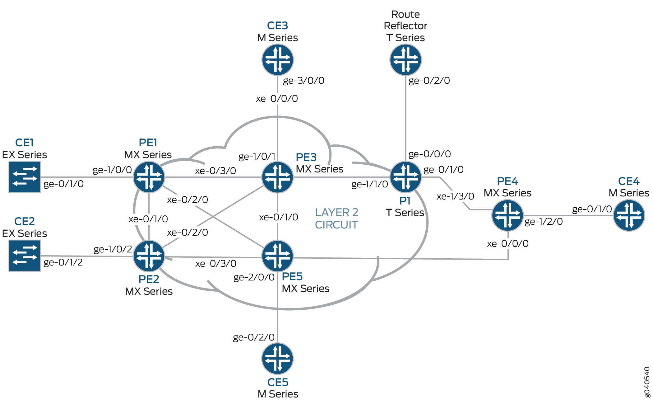
概述和拓扑
配置
在任何配置会话中,都最好定期验证可以使用命令提交 commit check 配置。
在此示例中,使用以下命令提示识别要配置的路由器:
CE1标识客户边缘 1 (CE1) 路由器PE1标识提供商边缘 1 (PE1) 路由器CE3标识客户边缘 3 (CE3) 路由器PE3标识提供商边缘 3 (PE3) 路由器CE5标识客户边缘 5 (CE5) 路由器PE5标识提供商边缘 5 (PE5) 路由器
此示例分以下部分进行组织:
在 PE 和 P 路由器上配置协议
逐步过程
所有 PE 路由器和 P 路由器均配置了 OSPF 作为 IGP 协议。除之外 fxp.0,所有接口均启用 MPLS、LDP 和 BGP 协议。面向核心的接口支持 MPLS 地址和 inet 地址。
将所有 PE 和 P 路由器配置为 OSPF 作为 IGP。在所有接口(除外
fxp.0)上启用 MPLS、LDP 和 BGP 协议。以下配置片段显示了路由器 PE1 的协议配置:[edit] protocols { mpls { interface all; interface fxp0.0 { disable; } } bgp { group RR { type internal; local-address 192.0.2.1; family l2vpn { signaling; } neighbor 192.0.2.7; } } ospf { traffic-engineering; area 0.0.0.0 { interface all; interface fxp0.0 { disable; } } } ldp { interface all; interface fxp0.0 { disable; } } }将 PE 和 P 路由器配置为 OSPF 作为 IGP。在所有接口(除外
fxp.0)上启用 MPLS、LDP 和 BGP 协议。以下配置片段显示了路由器 PE3 的协议配置:[edit] protocols { mpls { interface all; interface fxp0.0 { disable; } } bgp { group RR { type internal; local-address 192.0.2.3; family l2vpn { signaling; } neighbor 192.0.2.7; } } ospf { traffic-engineering; area 0.0.0.0 { interface all; interface fxp0.0 { disable; } } } ldp { interface all; interface fxp0.0 { disable; } } }
逐步过程
配置第 2 层 VPN 协议和接口
在路由器 PE1 上
ge-1/0/0,配置接口封装。要配置接口封装,请包含语句encapsulation并指定ethernet-ccc选项(也支持 vlan-ccc 封装)。ge-1/0/0.0配置逻辑接口系列以实现电路交叉连接功能。要配置逻辑接口系列,请包括family语句并指定ccc选项。对于第 2 层 VPN 域中的所有路由器,封装的配置方式应相同。[edit interfaces] ge-1/0/0 { encapsulation ethernet-ccc; unit 0 { family ccc; } } lo0 { unit 0 { family inet { address 192.0.2.1/24; } } }在路由器 PE1 上,配置第 2 层 VPN 协议。将远程站点 ID 配置为 3。站点 ID 3 表示路由器 PE3 (Hub-PE)。要配置第 2 层 VPN 协议,请在
l2vpn层级添加语句[edit routing-instances routing-instances-name protocols]。第 2 层 VPN 使用 BGP 作为信令协议。[edit routing-instances] L2VPN { instance-type l2vpn; interface ge-1/0/0.0; route-distinguisher 65000:1; vrf-target target:65000:2; protocols { l2vpn { encapsulation-type ethernet; site CE1 { site-identifier 1; interface ge-1/0/0.0 { remote-site-id 3; } } } } }在路由器 PE5 上
ge-2/0/0,通过包括encapsulation语句来配置接口封装并指定ethernet-ccc选项。通过包含family语句并指定ccc选项,配置 ge-1/0/0.0 逻辑接口系列,以实现电路交叉连接功能。[edit interfaces] ge-2/0/0 { encapsulation ethernet-ccc; unit 0 { family ccc; } } lo0 { unit 0 { family inet { address 192.0.2.5/24; } } }在路由器 PE5 上,通过在层次结构级别包含语句
[edit routing-instances routing-instances-name protocols]来l2vpn配置第 2 层 VPN 协议。将远程站点 ID 配置为3。[edit routing-instances] L2VPN { instance-type l2vpn; interface ge-2/0/0.0; route-distinguisher 65000:5; vrf-target target:65000:2; protocols { l2vpn { encapsulation-type ethernet; site CE5 { site-identifier 5; interface ge-2/0/0.0 { remote-site-id 3; } } } } }在路由器 PE3 上
iw0,使用两个逻辑接口配置接口。要配置iw0接口,请包含该interfaces语句并指定iw0为接口名称。对于单元 0 逻辑接口,包括语句,peer-unit并将逻辑接口unit 1指定为对等接口。对于单元 1 逻辑接口,包括语句,peer-unit并将逻辑接口unit 0指定为对等接口。[edit interfaces] iw0 { unit 0 { encapsulation ethernet-ccc; peer-unit 1; } unit 1 { encapsulation ethernet-ccc; peer-unit 0; } }在路由器 PE3 上,通过包括
encapsulation语句并指定选项来配置面向ge-1/0/1边缘的ethernet-ccc接口封装。[edit interfaces] ge-1/0/1 { encapsulation ethernet-ccc; unit 0 { family ccc; } }在路由器 PE3 上,配置逻辑环路接口。环路接口用于建立路由器 PE1 和路由器 PE5 的目标 LDP 会话。
[edit interfaces]
lo0 {
    unit 0 {
        family inet {
            address 192.0.2.3/24;
        }
    }
}
在路由器 PE3 上,启用第 2 层互连协议。要启用第 2 层互连协议,请将语句
l2iw包含在[edit protocols]层次结构级别。[edit protocols] l2iw;
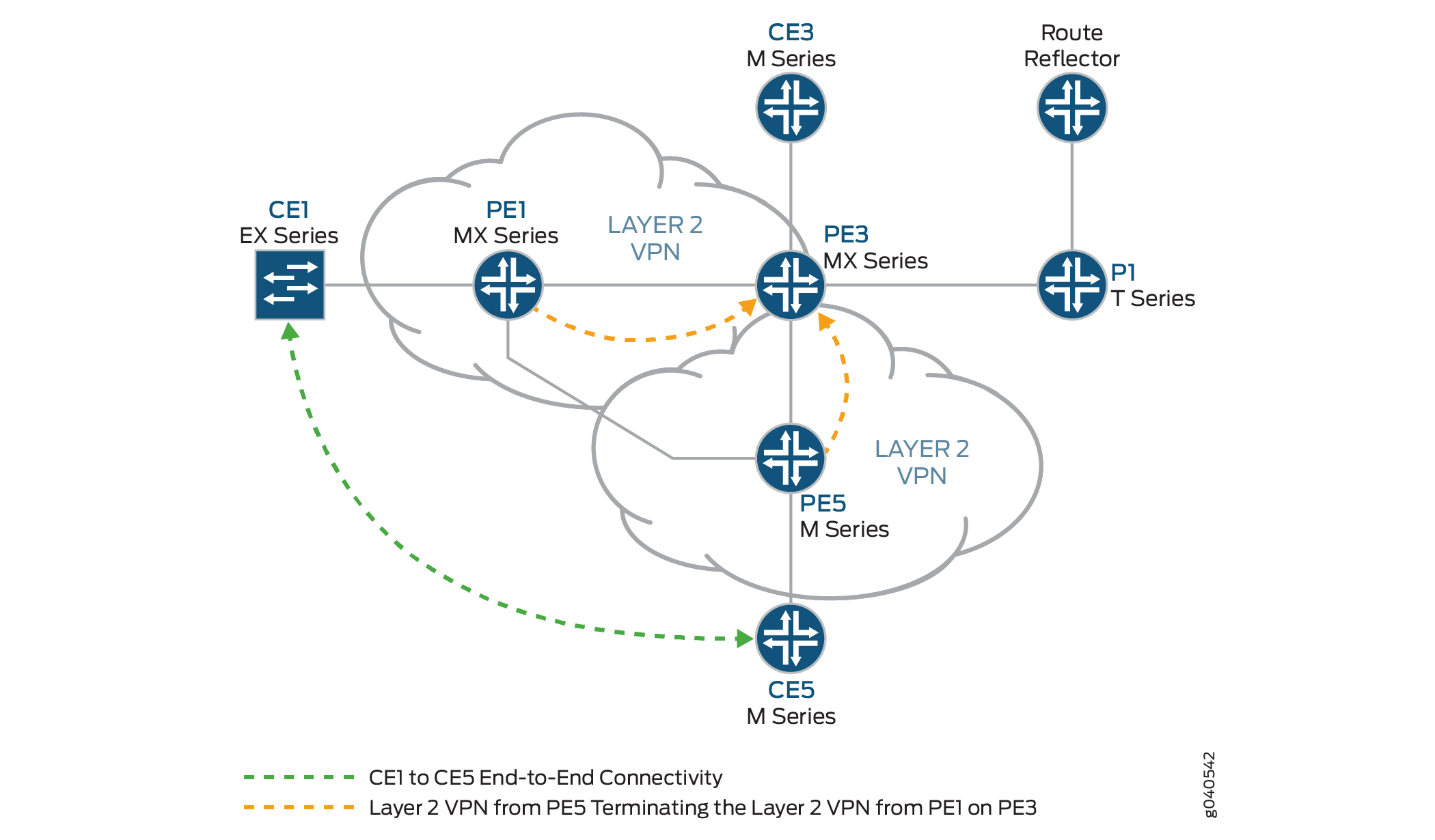
在路由器 PE3 上,配置两个第 2 层 VPN 路由实例,以从路由器 PE1 和路由器 PE5 终止第 2 层 VPN 虚拟电路,如图所示。
[edit routing-instances]
L2VPN-PE1 {
    instance-type l2vpn;
    interface iw0.0;
    route-distinguisher 65000:3;
    vrf-target target:65000:2;
    protocols {
        l2vpn {
            encapsulation-type ethernet;
            site CE3 {
                site-identifier 3;
                interface iw0.0 {
                    remote-site-id 1;
                }
            }
        }
    }
}
L2VPN-PE5 {
    instance-type l2vpn;
    interface iw0.1;
    route-distinguisher 65000:33;
    vrf-target target:65000:2;
    protocols {
        l2vpn {
            encapsulation-type ethernet;
            site CE3 {
                site-identifier 3;
                interface iw0.1 {
                    remote-site-id 5;
                }
            }
        }
    }
}
验证路由器 PE3 上的第 2 层 VPN 到第 2 层 VPN 连接
逐步过程
BGP 用于第 2 层 VPN 中的控制平面信令。在路由器 PE1 上,使用
show bgp命令验证第 2 层 VPN 的 BGP 控制平面是否与具有 IP 地址192.0.2.7的路由反射器建立了邻接关系。拓扑中的每个 PE 路由器的路由反射器接收三个第 2 层 VPN 路由。
user@PE1> show bgp summary
Groups: 1 Peers: 1 Down peers: 0
Table          Tot Paths  Act Paths Suppressed    History Damp State    Pending
bgp.l2vpn.0            3          3          0          0          0          0
Peer                     AS      InPkt     OutPkt    OutQ   Flaps Last Up/Dwn State|#Active/Received/Accepted/Damped...
192.0.2.7               65000        190        192       0       0     1:24:40 Establ
  bgp.l2vpn.0: 3/3/3/0
  L2VPN.l2vpn.0: 3/3/3/0
在路由器 PE1 上,使用
show route命令验证 BGP 第 2 层 VPN 路由是否已存储在每个 PE 路由器的L2VPN.l2vpn.0路由表中。user@PE1> show route table L2VPN.l2vpn.0 L2VPN.l2vpn.0: 4 destinations, 4 routes (4 active, 0 holddown, 0 hidden) + = Active Route, - = Last Active, * = Both 65000:1:1:3/96 *[L2VPN/170/-101] 01:31:53, metric2 1 Indirect 65000:3:3:1/96 *[BGP/170] 01:24:58, localpref 100, from 192.0.2.7 AS path: I > to 10.10.1.2 via xe-0/3/0.0 65000:5:5:3/96 *[BGP/170] 01:24:58, localpref 100, from 192.0.2.7 AS path: I > to 10.10.3.2 via xe-0/2/0.0 65000:33:3:5/96 *[BGP/170] 01:24:58, localpref 100, from 192.0.2.7 AS path: I > to 10.10.1.2 via xe-0/3/0.0在路由器 PE1 上,使用
show ldp session命令验证已与网络中的 PE 路由器建立目标 LDP 会话,以及状态是否为Operational。user@PE1> show ldp session Address State Connection Hold time 192.0.2.2 Operational Open 24 192.0.2.3 Operational Open 22 192.0.2.5 Operational Open 28
在路由器 PE1 上,使用
show l2vpn connections命令验证路由器 PE3 (Hub-PE) 上的第 2 层 VPN 到站点 3 是否为Up。user@PE1> show l2vpn connections Layer-2 VPN connections: Legend for connection status (St) EI -- encapsulation invalid NC -- interface encapsulation not CCC/TCC/VPLS EM -- encapsulation mismatch WE -- interface and instance encaps not same VC-Dn -- Virtual circuit down NP -- interface hardware not present CM -- control-word mismatch -> -- only outbound connection is up CN -- circuit not provisioned <- -- only inbound connection is up OR -- out of range Up -- operational OL -- no outgoing label Dn -- down LD -- local site signaled down CF -- call admission control failure RD -- remote site signaled down SC -- local and remote site ID collision LN -- local site not designated LM -- local site ID not minimum designated RN -- remote site not designated RM -- remote site ID not minimum designated XX -- unknown connection status IL -- no incoming label MM -- MTU mismatch MI -- Mesh-Group ID not availble BK -- Backup connection ST -- Standby connection PF -- Profile parse failure PB -- Profile busy Legend for interface status Up -- operational Dn -- down Instance: L2VPN Local site: CE1 (1) connection-site Type St Time last up # Up trans 3 rmt Up Jan 5 18:08:25 2010 1 Remote PE: 192.0.2.3, Negotiated control-word: Yes (Null) Incoming label: 800000, Outgoing label: 800000 Local interface: ge-1/0/0.0, Status: Up, Encapsulation: ETHERNET 5 rmt OR在路由器 PE1 上,使用
show route命令验证路由表是否mpls.0填充了用于使用 LDP 标签转发流量的第 2 层 VPN 路由。请注意,在此示例中,路由器正在推送标签8000000。user@PE1> show route table mpls.0 [edit] mpls.0: 13 destinations, 13 routes (13 active, 0 holddown, 0 hidden) + = Active Route, - = Last Active, * = Both 0 *[MPLS/0] 1w1d 11:36:44, metric 1 Receive 1 *[MPLS/0] 1w1d 11:36:44, metric 1 Receive 2 *[MPLS/0] 1w1d 11:36:44, metric 1 Receive 300432 *[LDP/9] 3d 04:25:02, metric 1 > to 10.10.2.2 via xe-0/1/0.0, Pop 300432(S=0) *[LDP/9] 3d 04:25:02, metric 1 > to 10.10.2.2 via xe-0/1/0.0, Pop 300768 *[LDP/9] 3d 04:25:02, metric 1 > to 10.10.3.2 via xe-0/2/0.0, Pop 300768(S=0) *[LDP/9] 3d 04:25:02, metric 1 > to 10.10.3.2 via xe-0/2/0.0, Pop 300912 *[LDP/9] 3d 04:25:02, metric 1 > to 10.10.3.2 via xe-0/2/0.0, Swap 299856 301264 *[LDP/9] 3d 04:24:58, metric 1 > to 10.10.1.2 via xe-0/3/0.0, Swap 308224 301312 *[LDP/9] 3d 04:25:01, metric 1 > to 10.10.1.2 via xe-0/3/0.0, Pop 301312(S=0) *[LDP/9] 3d 04:25:01, metric 1 > to 10.10.1.2 via xe-0/3/0.0, Pop 800000 *[L2VPN/7] 01:25:28 > via ge-1/0/0.0, Pop Offset: 4 ge-1/0/0.0 *[L2VPN/7] 01:25:28, metric2 1 > to 10.10.1.2 via xe-0/3/0.0, Push 800000 Offset: -4
验证路由器 PE3 上的第 2 层 VPN 到第 2 层 VPN 连接
逐步过程
在路由器 PE3 上,使用
show l2vpn connections命令验证路由器 PE1 和路由器 PE5 的第 2 层 VPN 连接是否Up正在使用接口iw0。user@PE3> show l2vpn connections Instance: L2VPN-PE1 Local site: CE3 (3) connection-site Type St Time last up # Up trans 1 rmt Up Jan 5 18:08:22 2010 1 Remote PE: 192.0.2.1, Negotiated control-word: Yes (Null) Incoming label: 800000, Outgoing label: 800000 Local interface: iw0.0, Status: Up, Encapsulation: ETHERNET 5 rmt OR Instance: L2VPN-PE5 Local site: CE3 (3) connection-site Type St Time last up # Up trans 1 rmt CN 5 rmt Up Jan 5 18:08:22 2010 1 Remote PE: 192.0.2.5, Negotiated control-word: Yes (Null) Incoming label: 800002, Outgoing label: 800000 Local interface: iw0.1, Status: Up, Encapsulation: ETHERNET在路由器 PE3 上,使用
show ldp neighbor命令验证是否显示了目标 LDP 会话邻接方 IP 地址。user@PE3> show ldp neighbor Address Interface Label space ID Hold time 192.0.2.1 lo0.0 192.0.2.1:0 44 192.0.2.2 lo0.0 192.0.2.2:0 42 192.0.2.4 lo0.0 192.0.2.4:0 31 192.0.2.5 lo0.0 192.0.2.5:0 44
在路由器 PE3 上,使用
show bgp summary命令验证第 2 层 VPN 的 BGP 控制平面是否与具有 IP 地址192.0.2.7的路由反射器建立了邻接关系。user@PE3> show bgp summary Groups: 1 Peers: 1 Down peers: 0 Table Tot Paths Act Paths Suppressed History Damp State Pending bgp.l2vpn.0 2 2 0 0 0 0 Peer AS InPkt OutPkt OutQ Flaps Last Up/Dwn State|#Active/Received/Accepted/Damped... 192.0.2.7 65000 10092 10195 0 0 3d 4:23:27 Establ bgp.l2vpn.0: 2/2/2/0 L2VPN-PE1.l2vpn.0: 2/2/2/0 L2VPN-PE5.l2vpn.0: 2/2/2/0
在路由器 PE3 上
show ldp session,使用命令验证已为网络中的所有 PE 路由器建立了目标 LDP 会话,并且状态是否为Operational。user@PE3> show ldp session Address State Connection Hold time 192.0.2.1
OperationalOpen 24 192.0.2.2OperationalOpen 22 192.0.2.4OperationalOpen 20 192.0.2.5OperationalOpen 24在路由器 PE3 上,使用
show route命令验证路由表是否mpls.0填充了用于使用 LDP 标签转发流量的第 2 层 VPN 路由。请注意,在此示例中,路由器正在交换标签800000。另请注意用于第 2 层互连路由的两个iw0接口。user@PE3>show route table mpls.0 mpls.0: 16 destinations, 18 routes (16 active, 2 holddown, 0 hidden) + = Active Route, - = Last Active, * = Both 0 *[MPLS/0] 1w1d 11:50:14, metric 1 Receive 1 *[MPLS/0] 1w1d 11:50:14, metric 1 Receive 2 *[MPLS/0] 1w1d 11:50:14, metric 1 Receive 308160 *[LDP/9] 3d 04:38:45, metric 1 > to 10.10.1.1 via xe-0/3/0.0, Pop 308160(S=0) *[LDP/9] 3d 04:38:45, metric 1 > to 10.10.1.1 via xe-0/3/0.0, Pop 308176 *[LDP/9] 3d 04:38:44, metric 1 > to 10.10.6.2 via xe-0/1/0.0, Pop 308176(S=0) *[LDP/9] 3d 04:38:44, metric 1 > to 10.10.6.2 via xe-0/1/0.0, Pop 308192 *[LDP/9] 00:07:18, metric 1 > to 10.10.20.1 via xe-0/0/0.0, Swap 601649 to 10.10.6.2 via xe-0/1/0.0, Swap 299856 308208 *[LDP/9] 3d 04:38:44, metric 1 > to 10.10.5.1 via xe-0/2/0.0, Pop 308208(S=0) *[LDP/9] 3d 04:38:44, metric 1 > to 10.10.5.1 via xe-0/2/0.0, Pop 308224 *[LDP/9] 3d 04:38:42, metric 1 > to 10.10.20.1 via xe-0/0/0.0, Pop 308224(S=0) *[LDP/9] 3d 04:38:42, metric 1 > to 10.10.20.1 via xe-0/0/0.0, Pop 800000 *[L2IW/6] 01:39:13, metric2 1 > to 10.10.6.2 via xe-0/1/0.0, Swap 800000 [L2VPN/7] 01:39:13 > via iw0.0, Pop Offset: 4 800002 *[L2IW/6] 01:39:13, metric2 1 > to 10.10.1.1 via xe-0/3/0.0, Swap 800000 [L2VPN/7] 01:39:13 > via iw0.1, Pop Offset: 4 iw0.0 *[L2VPN/7] 01:39:13, metric2 1 > to 10.10.1.1 via xe-0/3/0.0, Push 800000 Offset: -4 iw0.1 *[L2VPN/7] 01:39:13, metric2 1 > to 10.10.6.2 via xe-0/1/0.0, Push 800000 Offset: -4
逐步过程
测试 2 层 VPN 到 2 层 VPN 连接(CE1 到 CE5)
在路由器 CE1 上,使用
ping命令测试与路由器 CE5 的连接。请注意,响应时间以毫秒为单位,确认已返回 ping 响应。user@CE1>ping 198.51.100.11 PING 198.51.100.11 (198.51.100.11): 56 data bytes 64 bytes from 198.51.100.11: icmp_seq=1 ttl=64 time=22.425 ms 64 bytes from 198.51.100.11: icmp_seq=2 ttl=64 time=1.299 ms 64 bytes from 198.51.100.11: icmp_seq=3 ttl=64 time=1.032 ms 64 bytes from 198.51.100.11: icmp_seq=4 ttl=64 time=1.029 ms
在路由器 CE5 上,使用
ping命令测试与路由器 CE1 的连接。请注意,响应时间以毫秒为单位,确认已返回 ping 响应。user@CE5>ping 198.51.100.1 PING 198.51.100.1 (198.51.100.1): 56 data bytes 64 bytes from 198.51.100.1: icmp_seq=0 ttl=64 time=1.077 ms 64 bytes from 198.51.100.1: icmp_seq=1 ttl=64 time=0.957 ms 64 bytes from 198.51.100.1: icmp_seq=2 ttl=64 time=1.057 ms 1.017 ms
结果
此示例的配置和验证已完成。以下部分可供参考。
路由器 PE1 的相关配置示例如下。
路由器 PE1
chassis {
    dump-on-panic;
    fpc 1 {
        pic 3 {
            tunnel-services {
                bandwidth 1g;
            }
        }
    }
    network-services ethernet;
}
    interfaces {
        xe-0/1/0 {
            unit 0 {
                family inet {
                    address 10.10.2.1/30;
                }
                family mpls;
            }
        }
        xe-0/2/0 {
            unit 0 {
                family inet {
                    address 10.10.3.1/30;
                }
                family mpls;
            }
        }
        xe-0/3/0 {
            unit 0 {
                family inet {
                    address 10.10.1.1/30;
                }
                family mpls;
            }
        }
        ge-1/0/0 {
            encapsulation ethernet-ccc;
            unit 0 {
                family ccc;
            }
        }
        lo0 {
            unit 0 {
                family inet {
                    address 192.0.2.1/24;
                }
            }
        }
    }
    routing-options {
        static {
            route 172.16.0.0/8 next-hop 172.19.59.1;
        }
        autonomous-system 65000;
    }
    protocols {
        mpls {
            interface all;
            interface fxp0.0 {
                disable;
            }
        }
        bgp {
            group RR {
                type internal;
                local-address 192.0.2.1;
                family l2vpn {
                    signaling;
                }
                neighbor 192.0.2.7;
            }
        }
        ospf {
            traffic-engineering;
            area 0.0.0.0 {
                interface all;
                interface fxp0.0 {
                    disable;
                }
            }
        }
        ldp {
            interface all;
            interface fxp0.0 {
                disable;
            }
        }
    }
    routing-instances {
        L2VPN {
            instance-type l2vpn;
            interface ge-1/0/0.0;
            route-distinguisher 65000:1;
            vrf-target target:65000:2;
            protocols {
                l2vpn {
                    encapsulation-type ethernet;
                    site CE1 {
                        site-identifier 1;
                        interface ge-1/0/0.0 {
                            remote-site-id 3;
                        }
                    }
                }
            }
        }
    }
路由器 PE3 的相关配置示例如下。
路由器 PE3
chassis {
    dump-on-panic;
    fpc 1 {
        pic 3 {
            tunnel-services {
                bandwidth 1g;
            }
        }
    }
    network-services ethernet;
}
interfaces {
    xe-0/0/0 {
        unit 0 {
            family inet {
                address 10.10.20.2/30;
            }
            family mpls;
        }
    }
    xe-0/1/0 {
        unit 0 {
            family inet {
                address 10.10.6.1/30;
            }
            family mpls;
        }
    }
    xe-0/2/0 {
        unit 0 {
            family inet {
                address 10.10.5.2/30;
            }
            family mpls;
        }
    }
    xe-0/3/0 {
        unit 0 {
            family inet {
                address 10.10.1.2/30;
            }
            family mpls;
        }
    }
    ge-1/0/1 {
        encapsulation ethernet-ccc;
        unit 0 {
            family ccc;
        }
    }
    iw0 {
        unit 0 {
            encapsulation ethernet-ccc;
            peer-unit 1;
        }
        unit 1 {
            encapsulation ethernet-ccc;
            peer-unit 0;
        }
    }
    lo0 {
        unit 0 {
            family inet {
                address 192.0.2.3/24;
            }
        }
    }
}
routing-options {
    static {
        route 172.16.0.0/8 next-hop 172.19.59.1;
    }
    autonomous-system 65000;
}
protocols {
    l2iw;
    mpls {
        interface all;
        interface fxp0.0 {
            disable;
        }
    }
    bgp {
        group RR {
            type internal;
            local-address 192.0.2.3;
            family l2vpn {
                signaling;
            }
            neighbor 192.0.2.7;
        }
    }
    ospf {
        area 0.0.0.0 {
            interface all;
            interface fxp0.0 {
                disable;
            }
        }
    }
    ldp {
        interface all;
        interface fxp0.0 {
            disable;
        }
    }
}
routing-instances {
    L2VPN-PE1 {
        instance-type l2vpn;
        interface iw0.0;
        route-distinguisher 65000:3;
        vrf-target target:65000:2;
        protocols {
            l2vpn {
                encapsulation-type ethernet;
                site CE3 {
                    site-identifier 3;
                    interface iw0.0 {
                        remote-site-id 1;
                    }
                }
            }
        }
    }
    L2VPN-PE5 {
        instance-type l2vpn;
        interface iw0.1;
        route-distinguisher 65000:33;
        vrf-target target:65000:2;
        protocols {
            l2vpn {
                encapsulation-type ethernet;
                site CE3 {
                    site-identifier 3;
                    interface iw0.1 {
                        remote-site-id 5;
                    }
                }
            }
        }
    }
}